EP0990518B1 - Druckmaschinenzylinder, insbesondere Gegendruckzylinder für eine Bogenrotationsdruckmaschine - Google Patents
Druckmaschinenzylinder, insbesondere Gegendruckzylinder für eine Bogenrotationsdruckmaschine Download PDFInfo
- Publication number
- EP0990518B1 EP0990518B1 EP99119228A EP99119228A EP0990518B1 EP 0990518 B1 EP0990518 B1 EP 0990518B1 EP 99119228 A EP99119228 A EP 99119228A EP 99119228 A EP99119228 A EP 99119228A EP 0990518 B1 EP0990518 B1 EP 0990518B1
- Authority
- EP
- European Patent Office
- Prior art keywords
- cylinder
- recesses
- covering element
- impression cylinder
- suction
- Prior art date
- Legal status (The legal status is an assumption and is not a legal conclusion. Google has not performed a legal analysis and makes no representation as to the accuracy of the status listed.)
- Expired - Lifetime
Links
- 238000007639 printing Methods 0.000 title claims description 35
- 238000004519 manufacturing process Methods 0.000 claims abstract description 12
- 230000002093 peripheral effect Effects 0.000 claims description 39
- 238000007664 blowing Methods 0.000 claims description 12
- 238000007514 turning Methods 0.000 claims description 12
- 238000011144 upstream manufacturing Methods 0.000 claims description 7
- 238000000034 method Methods 0.000 claims description 4
- 239000007787 solid Substances 0.000 claims description 3
- 230000003247 decreasing effect Effects 0.000 claims description 2
- 238000009826 distribution Methods 0.000 description 8
- 238000003754 machining Methods 0.000 description 6
- 238000005266 casting Methods 0.000 description 2
- 238000005553 drilling Methods 0.000 description 2
- 239000011888 foil Substances 0.000 description 2
- 239000002184 metal Substances 0.000 description 2
- 229910052751 metal Inorganic materials 0.000 description 2
- VYZAMTAEIAYCRO-UHFFFAOYSA-N Chromium Chemical group [Cr] VYZAMTAEIAYCRO-UHFFFAOYSA-N 0.000 description 1
- 206010010774 Constipation Diseases 0.000 description 1
- 229910001060 Gray iron Inorganic materials 0.000 description 1
- 238000004026 adhesive bonding Methods 0.000 description 1
- 239000011324 bead Substances 0.000 description 1
- 230000006735 deficit Effects 0.000 description 1
- 239000000428 dust Substances 0.000 description 1
- 238000005516 engineering process Methods 0.000 description 1
- 238000005530 etching Methods 0.000 description 1
- 239000011521 glass Substances 0.000 description 1
- 230000001771 impaired effect Effects 0.000 description 1
- 239000012535 impurity Substances 0.000 description 1
- 239000002245 particle Substances 0.000 description 1
- 230000000149 penetrating effect Effects 0.000 description 1
- 238000003860 storage Methods 0.000 description 1
- 238000003466 welding Methods 0.000 description 1
Images


Classifications
-
- B—PERFORMING OPERATIONS; TRANSPORTING
- B65—CONVEYING; PACKING; STORING; HANDLING THIN OR FILAMENTARY MATERIAL
- B65H—HANDLING THIN OR FILAMENTARY MATERIAL, e.g. SHEETS, WEBS, CABLES
- B65H45/00—Folding thin material
- B65H45/12—Folding articles or webs with application of pressure to define or form crease lines
-
- B—PERFORMING OPERATIONS; TRANSPORTING
- B41—PRINTING; LINING MACHINES; TYPEWRITERS; STAMPS
- B41F—PRINTING MACHINES OR PRESSES
- B41F13/00—Common details of rotary presses or machines
- B41F13/08—Cylinders
- B41F13/18—Impression cylinders
-
- B—PERFORMING OPERATIONS; TRANSPORTING
- B41—PRINTING; LINING MACHINES; TYPEWRITERS; STAMPS
- B41F—PRINTING MACHINES OR PRESSES
- B41F21/00—Devices for conveying sheets through printing apparatus or machines
- B41F21/10—Combinations of transfer drums and grippers
- B41F21/102—Combinations of transfer drums and grippers with pneumatic means
-
- B—PERFORMING OPERATIONS; TRANSPORTING
- B41—PRINTING; LINING MACHINES; TYPEWRITERS; STAMPS
- B41N—PRINTING PLATES OR FOILS; MATERIALS FOR SURFACES USED IN PRINTING MACHINES FOR PRINTING, INKING, DAMPING, OR THE LIKE; PREPARING SUCH SURFACES FOR USE AND CONSERVING THEM
- B41N7/00—Shells for rollers of printing machines
-
- B—PERFORMING OPERATIONS; TRANSPORTING
- B41—PRINTING; LINING MACHINES; TYPEWRITERS; STAMPS
- B41N—PRINTING PLATES OR FOILS; MATERIALS FOR SURFACES USED IN PRINTING MACHINES FOR PRINTING, INKING, DAMPING, OR THE LIKE; PREPARING SUCH SURFACES FOR USE AND CONSERVING THEM
- B41N2207/00—Location or type of the layers in shells for rollers of printing machines
- B41N2207/02—Top layers
Definitions
- the invention relates to a Impression cylinder for a sheet-fed rotary printing press and a method for Production of such a printing press cylinder.
- a transfer cylinder for a Sheet-fed rotary printing machine is known, the one formed from four support disks Has cylinder body on which a total of three support elements are attached. each the support elements have a sandwich-like structure, in the middle of which suction chambers be defined by a meandering bent sheet metal, which to the outside of the cylinder through a thin-walled and corresponding to the cylinder curvature curved jacket sheet is covered.
- Each of the chambers is assigned via Openings in the casing sheet are connected to the environment in terms of flow and can be via a rotary valve can be supplied with suction air in order to form an arc on the Suction and smooth the peripheral surface of the cylinder. Because of education of the chambers used thin-walled corrugated sheet and the associated Sandwich-like structure of the cylinder is not suitable for use as Impression cylinder in a printing unit of a sheet-fed rotary printing press.
- EP 0 165 477 B1 describes a sheet-fed rotary printing press with a Known turning device, which one upstream of the turning device Counter-pressure cylinder on which the sheet to be turned sucked and being held.
- the impression cylinder has a solid base, in which suction air or axially extending over the entire cylinder width Blown air supply channels are incorporated. Extends from each of the feed channels a plurality of radially extending holes to the peripheral surface of the Cylinder body. On the peripheral surface of the cylinder body is still a structural film is applied, which is porous in the region of the radially running bores is or has openings through which a transported on the cylinder Bow sucked against the peripheral surface or can be lifted from this.
- JP-A-09/123395 discloses an impression cylinder for a sheet-fed printing machine with a cylinder body with a variety of suction holes on its peripheral surface a porous film is applied.
- the object of the invention is to be achieved an impression cylinder for a sheet-fed rotary printing press create which is easy and inexpensive to manufacture and which one Suction, as well as blowing off sheets guided on the cylinder.
- an object of the invention to provide a manufacturing method with which an impression cylinder one Sheet-fed rotary printing press, the one with blowing or suction openings Has peripheral surface, can be manufactured in a simple and inexpensive manner.
- impression cylinder according to the invention and the method according to the invention for the production of such are based on preferred Embodiments described with reference to the drawings.
- the printing press cylinder 1 shown schematically in FIG. 1, the as a cooperating with an associated blanket cylinder 2 Impression cylinder used in a printing unit 4 of a sheet-fed rotary printing press comprises a base body 8, which in the preferred embodiment of the Invention as a casting provided with cavities 6 and ribs 10, for example made of Gray cast iron, etc. is formed.
- the impression cylinder 1 according to the invention preferably in one Turning device 12 upstream printing unit 4 used.
- the turning device 12 is in Fig. 1 schematically by an unspecified suction pad and a Takeover gripper having reversing drum 14 indicated
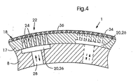
- the impression cylinder 1 shown in FIGS. 2 to 4 are in the base body 8 Recesses 20 are incorporated, for example after casting the base body 8 can be milled into the same during rough machining.
- the recesses 20 define air distribution chambers 26, which have a Air supply line 28 with a blowing or suction air source, not shown are connectable, the flow connection between blown air or Suction air source and the air distribution chambers 26 preferably via one or more, in Fig. 1 schematically shown as a block valves 30 and a control device 32 in Form of a known rotary union or a rotary valve can be done.
- the circumferential surface of the cylinder base body 8 is the same applied a solid jacket body 17, for. B. axially slid on can have a thickness in the range of 10 mm, for example, and in the range of the recesses 20 through channels 24 are formed, the blowing suction areas or Define sections 22 on the peripheral surface 18 of the cylinder.
- each of the Through channels 24 one from the center of the cylinder in the Sheath body 17 introduced channel section 24a of larger diameter, as well as several arranged above and communicating with section 24a Sections 24b with a much smaller diameter.
- the diameter the channel sections 24a can for example be in the range between 0.5 mm and 1.5 mm, whereas the diameter of the channel portions 24b is in the range of Can be 0.05 to 0.2 mm.
- Printing press cylinder 1 can be on the outer peripheral surface of the jacket body 17th a porous film 34 may be applied in which the channel sections are smaller Diameter 24b, e.g. B. are formed by a laser or by etching, etc.
- porous Structural foils e.g. B. in the form of glass bead cloths or so-called Chrome structure elevators are known for example from EP 0 165 477.
- the slide 34 can, for example, be clamped on the peripheral surface 18 of the jacket body 17 or but also be glued on and is used when using an inventive Cylinder 1 acting as a counter-pressure cylinder in the pressure gap in the area of Distribute through channels 24 evenly to prevent the occurrence of imprints to avoid the channels 24 in the printed image.
- the channel sections 24a of the through channels 24 one towards the air distribution chamber 26 have a widening cross section in the area of the air distribution chambers 26 for example double the cross section at the opposite end of the Through channels can be 24. This results in the case of suction air operation of the printing press cylinder 1 compared to a considerably reduced susceptibility to failure Constipation, which e.g. B. by penetrating into the through channels 24 paper dust or can be brought about by other particles.
- the production of the casing body 17 with the through channels 24 arranged therein is advantageously carried out independently of the machining of the cylinder base body 8.
- the multiplicity of the circumferential surface 18 of the casing body 17 Through channels to be introduced 24 z. B. with the help of suitable tools such as Drill batteries or laser machining tools take place, which results in manufacturing technology result in considerable advantages. So it comes as a result of separate processing, for example when a drilling tool breaks when drilling the Through channels 24 do not damage the considerably more expensive manufacturing cylinder body 8, as z. B. in the manufacture of Printing machine cylinders according to the prior art is the case in which the channels usually directly into the peripheral surface of the one-piece formed Cylinder body are introduced. Furthermore, the processing time by separate processing of jacket body 17 and cylinder base body 8 considerably reduced, because part of the one-piece cylinders to be carried out one after the other Processing steps now simultaneously on different processing devices can be carried out.
- the cylinder jacket body in the manner described above preferably by Machining a flat metal plate was made, this is on the Circumferential surface of the roughly pre-machined cylinder body 8 applied and on this z. B. by screwing from the inside or by gluing or welding attached.
- the jacket body 17 z. B. by a plastic deformation process previously with one of the curvature of the Outer peripheral surface of the cylinder base body 8 corresponding permanent curvature is provided so that the jacket body 17 is essentially stress-free on the Cylinder base body 8 is held.
- the Sheath body 17 previously provided with a greater curvature than the cylinder curvature is, so that after application to the cylinder body 8 in the Is biased outside.
- the blowing-suction sections 22 have the shape of strips. in this connection are preferably separated along one of the groove-shaped recesses 20a Air distribution chambers 26 which can be acted upon from one another with blown air or suction air arranged.
- the grooves 20a can be both in the circumferential direction and in the axial Extend direction along the peripheral surface 18 of the press cylinder 1.
- the blow suction sections 22 are on the Circumferential surface 18 of the cylinder 1 is preferably arranged in rows 40, which are both in the circumferential direction and in the axial direction via the Can extend circumferential surface 18.
- the rows 40 are substantially V-shaped or radiating on the Circumferential surface 18 of the cylinder 1 run. This can be achieved, for example be that the axially extending rows 40 a - in the direction of rotation 42nd of the cylinder 1 seen - have decreasing length, which in the case of small-sized sheet 16a only that in the area of the sheet trailing edge 44a in the middle the blowing - suction sections 22 of the peripheral surface 18 of the cylinder 1 suck in small-format sheet 16a.
- the Blow - suction sections 22 of the axially extending rows 40, or their Air distribution chambers 26 preferably in groups with blown air or suction air acted upon, the application depending on the to be processed Sheet format takes place in such a way that only those conveyed below one on the cylinder Blows air or suction air are applied to sections 16 located on the arc 16.
- the control device 32 preferably all sections 22 or their Air distribution chambers 26 via the control device 32 in the form of a known one Rotary union at the same time as the suction air or blast air source via the Valve block 30 connected.
- the rows 40 of blow suction sections 22 of a certain predetermined angle of rotation position progressively with blowing air or Blowing air blasts are applied to the sheet 16 from the peripheral surface 18th detach or to clean the channels 24 of impurities.
- an impression cylinder in a printing unit upstream of a turning device turned out to be advantageous, arranged along an axial row 40 Sections 22, or their manifold chambers 26 in the area between the pressure gap and the transfer centers 46 to the downstream turning drum 14 (FIG. 1) with suction air act and the corresponding axial rows 40 below the Trailing edge 44a, 44b only immediately before, or immediately after, the grasping Trailing edge 44a, 44b by a gripper device of the turning drum 14 To apply blown air to the sheet 16 sucked on the peripheral surface 18 detach from this.
Landscapes
- Engineering & Computer Science (AREA)
- Mechanical Engineering (AREA)
- Supply, Installation And Extraction Of Printed Sheets Or Plates (AREA)
- Rotary Presses (AREA)
- Feeding Of Articles By Means Other Than Belts Or Rollers (AREA)
- Rolls And Other Rotary Bodies (AREA)
- Perforating, Stamping-Out Or Severing By Means Other Than Cutting (AREA)
Applications Claiming Priority (2)
| Application Number | Priority Date | Filing Date | Title |
|---|---|---|---|
| DE19845214A DE19845214A1 (de) | 1998-10-01 | 1998-10-01 | Druckmaschinenzylinder, insbesondere Gegendruckzylinder für eine Bogenrotationsmaschine |
| DE19845214 | 1998-10-01 |
Publications (3)
| Publication Number | Publication Date |
|---|---|
| EP0990518A2 EP0990518A2 (de) | 2000-04-05 |
| EP0990518A3 EP0990518A3 (de) | 2000-11-08 |
| EP0990518B1 true EP0990518B1 (de) | 2003-04-16 |
Family
ID=7883046
Family Applications (1)
| Application Number | Title | Priority Date | Filing Date |
|---|---|---|---|
| EP99119228A Expired - Lifetime EP0990518B1 (de) | 1998-10-01 | 1999-09-28 | Druckmaschinenzylinder, insbesondere Gegendruckzylinder für eine Bogenrotationsdruckmaschine |
Country Status (5)
| Country | Link |
|---|---|
| US (1) | US6581517B1 (https=) |
| EP (1) | EP0990518B1 (https=) |
| JP (1) | JP4495278B2 (https=) |
| AT (1) | ATE237472T1 (https=) |
| DE (2) | DE19845214A1 (https=) |
Cited By (3)
| Publication number | Priority date | Publication date | Assignee | Title |
|---|---|---|---|---|
| DE102014011411A1 (de) | 2014-07-31 | 2016-02-04 | Heidelberger Druckmaschinen Ag | Bogentransportvorrichtung |
| DE102014224833A1 (de) | 2014-12-04 | 2016-06-09 | Heidelberger Druckmaschinen Ag | Saugfläche |
| DE102015225605A1 (de) | 2015-12-17 | 2017-06-22 | Heidelberger Druckmaschinen Ag | Bogentransportvorrichtung und Verfahren zum Bogentransport |
Families Citing this family (68)
| Publication number | Priority date | Publication date | Assignee | Title |
|---|---|---|---|---|
| US7107907B2 (en) * | 2001-01-22 | 2006-09-19 | Goss International Americas, Inc. | Flow-restricted printing cylinder for a removable printing sleeve |
| ATE418452T1 (de) | 2002-10-30 | 2009-01-15 | Heidelberger Druckmasch Ag | Bogentransporttrommel einer bedruckstoffbogen verarbeitenden maschine |
| US6983692B2 (en) * | 2003-10-31 | 2006-01-10 | Hewlett-Packard Development Company, L.P. | Printing apparatus with a drum and screen |
| US7703599B2 (en) | 2004-04-19 | 2010-04-27 | Curt G. Joa, Inc. | Method and apparatus for reversing direction of an article |
| US8417374B2 (en) | 2004-04-19 | 2013-04-09 | Curt G. Joa, Inc. | Method and apparatus for changing speed or direction of an article |
| US7640962B2 (en) | 2004-04-20 | 2010-01-05 | Curt G. Joa, Inc. | Multiple tape application method and apparatus |
| US20050230037A1 (en) | 2004-04-20 | 2005-10-20 | Curt G. Joa, Inc. | Staggered cutting knife |
| US7708849B2 (en) | 2004-04-20 | 2010-05-04 | Curt G. Joa, Inc. | Apparatus and method for cutting elastic strands between layers of carrier webs |
| US7638014B2 (en) | 2004-05-21 | 2009-12-29 | Curt G. Joa, Inc. | Method of producing a pants-type diaper |
| US7537215B2 (en) * | 2004-06-15 | 2009-05-26 | Curt G. Joa, Inc. | Method and apparatus for securing stretchable film using vacuum |
| US7811403B2 (en) | 2005-03-09 | 2010-10-12 | Curt G. Joa, Inc. | Transverse tab application method and apparatus |
| CA2600432C (en) | 2005-03-09 | 2013-07-16 | Curt G. Joa, Inc. | Transverse tape application method and apparatus |
| US8007484B2 (en) | 2005-04-01 | 2011-08-30 | Curt G. Joa, Inc. | Pants type product and method of making the same |
| US20060265867A1 (en) * | 2005-05-31 | 2006-11-30 | Curt G. Joa, Inc. | Use of ultrasonic horn to mechanically secure hooks to a smooth material web |
| US7618513B2 (en) | 2005-05-31 | 2009-11-17 | Curt G. Joa, Inc. | Web stabilization on a slip and cut applicator |
| US7533709B2 (en) | 2005-05-31 | 2009-05-19 | Curt G. Joa, Inc. | High speed vacuum porting |
| US7770712B2 (en) | 2006-02-17 | 2010-08-10 | Curt G. Joa, Inc. | Article transfer and placement apparatus with active puck |
| US7975584B2 (en) | 2007-02-21 | 2011-07-12 | Curt G. Joa, Inc. | Single transfer insert placement method and apparatus |
| US9433538B2 (en) | 2006-05-18 | 2016-09-06 | Curt G. Joa, Inc. | Methods and apparatus for application of nested zero waste ear to traveling web and formation of articles using a dual cut slip unit |
| US10456302B2 (en) | 2006-05-18 | 2019-10-29 | Curt G. Joa, Inc. | Methods and apparatus for application of nested zero waste ear to traveling web |
| US9622918B2 (en) | 2006-05-18 | 2017-04-18 | Curt G. Joe, Inc. | Methods and apparatus for application of nested zero waste ear to traveling web |
| US7780052B2 (en) * | 2006-05-18 | 2010-08-24 | Curt G. Joa, Inc. | Trim removal system |
| US8172977B2 (en) | 2009-04-06 | 2012-05-08 | Curt G. Joa, Inc. | Methods and apparatus for application of nested zero waste ear to traveling web |
| US8016972B2 (en) | 2007-05-09 | 2011-09-13 | Curt G. Joa, Inc. | Methods and apparatus for application of nested zero waste ear to traveling web |
| DE102006046624A1 (de) * | 2006-09-29 | 2008-04-03 | Brötje-Automation GmbH | Verfahren und Transportvorrichtung zum Transportieren von Gegenständen |
| US9944487B2 (en) | 2007-02-21 | 2018-04-17 | Curt G. Joa, Inc. | Single transfer insert placement method and apparatus |
| US9550306B2 (en) | 2007-02-21 | 2017-01-24 | Curt G. Joa, Inc. | Single transfer insert placement and apparatus with cross-direction insert placement control |
| US7963224B2 (en) * | 2007-03-23 | 2011-06-21 | Hewlett-Packard Development Company, L.P. | Drum having a polymer layer with channels on a metal cylinder |
| CN101269760B (zh) * | 2007-03-23 | 2011-11-16 | 海德堡印刷机械股份公司 | 收纸滚筒及双面印刷机 |
| US9387131B2 (en) | 2007-07-20 | 2016-07-12 | Curt G. Joa, Inc. | Apparatus and method for minimizing waste and improving quality and production in web processing operations by automated threading and re-threading of web materials |
| US8398793B2 (en) | 2007-07-20 | 2013-03-19 | Curt G. Joa, Inc. | Apparatus and method for minimizing waste and improving quality and production in web processing operations |
| US20090057998A1 (en) * | 2007-08-31 | 2009-03-05 | Pitney Bowes Inc. | Apparatus and Method for Printing And/Or Electronically Scanning Dual Face Surfaces of a Sheet/Mailpiece |
| US8182624B2 (en) | 2008-03-12 | 2012-05-22 | Curt G. Joa, Inc. | Registered stretch laminate and methods for forming a registered stretch laminate |
| DE102010001098A1 (de) | 2009-01-27 | 2010-08-12 | Manroland Ag | Bogenführende Trommel für ein Bogenwendesystem einer Bogendruckmaschine |
| JP5433261B2 (ja) * | 2009-03-11 | 2014-03-05 | 株式会社小森コーポレーション | シート状物案内装置 |
| US8673098B2 (en) | 2009-10-28 | 2014-03-18 | Curt G. Joa, Inc. | Method and apparatus for stretching segmented stretchable film and application of the segmented film to a moving web |
| US8460495B2 (en) | 2009-12-30 | 2013-06-11 | Curt G. Joa, Inc. | Method for producing absorbent article with stretch film side panel and application of intermittent discrete components of an absorbent article |
| US9089453B2 (en) | 2009-12-30 | 2015-07-28 | Curt G. Joa, Inc. | Method for producing absorbent article with stretch film side panel and application of intermittent discrete components of an absorbent article |
| IT1399457B1 (it) * | 2010-03-15 | 2013-04-19 | Rent Srl | Gruppo di piega di macchina piegatrice ad alta velocità |
| US8663411B2 (en) | 2010-06-07 | 2014-03-04 | Curt G. Joa, Inc. | Apparatus and method for forming a pant-type diaper with refastenable side seams |
| US9603752B2 (en) | 2010-08-05 | 2017-03-28 | Curt G. Joa, Inc. | Apparatus and method for minimizing waste and improving quality and production in web processing operations by automatic cuff defect correction |
| US20120157279A1 (en) * | 2010-12-20 | 2012-06-21 | Uwe Schneider | Process and Apparatus for Joining Flexible Components |
| US9566193B2 (en) | 2011-02-25 | 2017-02-14 | Curt G. Joa, Inc. | Methods and apparatus for forming disposable products at high speeds with small machine footprint |
| US8656817B2 (en) | 2011-03-09 | 2014-02-25 | Curt G. Joa | Multi-profile die cutting assembly |
| USD684613S1 (en) | 2011-04-14 | 2013-06-18 | Curt G. Joa, Inc. | Sliding guard structure |
| US8820380B2 (en) | 2011-07-21 | 2014-09-02 | Curt G. Joa, Inc. | Differential speed shafted machines and uses therefor, including discontinuous and continuous side by side bonding |
| PL2628472T3 (pl) | 2012-02-20 | 2016-07-29 | Joa Curt G Inc | Sposób tworzenia spojeń między oddzielnymi częściami składowymi produktów jednorazowego użytku |
| US9908739B2 (en) | 2012-04-24 | 2018-03-06 | Curt G. Joa, Inc. | Apparatus and method for applying parallel flared elastics to disposable products and disposable products containing parallel flared elastics |
| CN105008259B (zh) | 2013-02-06 | 2016-09-14 | Jdc股份有限公司 | 吸辊装置 |
| US9283683B2 (en) | 2013-07-24 | 2016-03-15 | Curt G. Joa, Inc. | Ventilated vacuum commutation structures |
| USD703248S1 (en) | 2013-08-23 | 2014-04-22 | Curt G. Joa, Inc. | Ventilated vacuum commutation structure |
| USD703712S1 (en) | 2013-08-23 | 2014-04-29 | Curt G. Joa, Inc. | Ventilated vacuum commutation structure |
| USD703247S1 (en) | 2013-08-23 | 2014-04-22 | Curt G. Joa, Inc. | Ventilated vacuum commutation structure |
| USD704237S1 (en) | 2013-08-23 | 2014-05-06 | Curt G. Joa, Inc. | Ventilated vacuum commutation structure |
| USD703711S1 (en) | 2013-08-23 | 2014-04-29 | Curt G. Joa, Inc. | Ventilated vacuum communication structure |
| US9289329B1 (en) | 2013-12-05 | 2016-03-22 | Curt G. Joa, Inc. | Method for producing pant type diapers |
| JP6270133B2 (ja) * | 2014-02-12 | 2018-01-31 | 株式会社小森コーポレーション | フレキシブル電子デバイス製造装置 |
| JP6529347B2 (ja) * | 2015-06-05 | 2019-06-12 | 株式会社小森コーポレーション | 印刷機 |
| WO2017019544A1 (en) | 2015-07-24 | 2017-02-02 | Curt G. Joa, Inc. | Vacuum commutation apparatus and methods |
| CN105644135B (zh) * | 2016-02-02 | 2018-01-12 | 京东方科技集团股份有限公司 | 转印设备和涂布机 |
| PL3243660T3 (pl) * | 2016-05-09 | 2019-03-29 | Flint Group Germany Gmbh | Cylinder z częściowo gazoprzepuszczalną powierzchnią |
| JP6702005B2 (ja) * | 2016-06-15 | 2020-05-27 | 株式会社リコー | シート材搬送ユニット、シート材搬送装置及び液体を吐出する装置 |
| DE102019207708A1 (de) * | 2018-07-03 | 2020-01-09 | Heidelberger Druckmaschinen Ag | Verfahren zum Betrieb einer Wendeeinrichtung einer Druckmaschine |
| JP2021116156A (ja) * | 2020-01-27 | 2021-08-10 | 株式会社リコー | シート吸引装置、シート搬送装置、印刷装置、吸引領域切替装置 |
| JP7443791B2 (ja) * | 2020-01-31 | 2024-03-06 | 株式会社リコー | シート吸引装置、シート搬送装置、印刷装置、吸引領域切替装置 |
| US11737930B2 (en) | 2020-02-27 | 2023-08-29 | Curt G. Joa, Inc. | Configurable single transfer insert placement method and apparatus |
| CN112918092B (zh) * | 2021-02-05 | 2022-11-11 | 明光市瑞洁日用品有限公司 | 一种纺织品印花装置 |
| WO2026017250A1 (de) * | 2024-07-17 | 2026-01-22 | manroland sheetfed GmbH | Bogenführender zylinder mit saugnut sowie verfahren zur beeinflussung der sauglänge innerhalb der saugnut |
Citations (1)
| Publication number | Priority date | Publication date | Assignee | Title |
|---|---|---|---|---|
| EP0165477A2 (de) * | 1984-06-16 | 1985-12-27 | Heidelberger Druckmaschinen Aktiengesellschaft | Folie für bogenführende Zylinder und Trommeln in Rotationsoffsetdruckmaschinen und Verwendung derselben |
Family Cites Families (31)
| Publication number | Priority date | Publication date | Assignee | Title |
|---|---|---|---|---|
| GB789681A (en) * | 1955-05-18 | 1958-01-29 | Albert Edwards | Improvements relating to sheet feeding apparatus for printing machines |
| DE1147243B (de) * | 1962-03-16 | 1963-04-18 | Georg Spiess Dr Ing | Saugrad bzw. Saugwalze fuer die Foerderung von Bogen bei Bogenanlegern |
| US3710470A (en) * | 1970-09-03 | 1973-01-16 | Kimberly Clark Co | Jacketed press roll |
| DE2509680A1 (de) * | 1975-03-06 | 1976-09-16 | Hoechst Ag | Verfahren und vorrichtung zum kontinuierlichen farbigen bedrucken von flaechenhaften gebilden in bahnform |
| CH598110A5 (https=) * | 1975-10-10 | 1978-04-28 | Gretag Ag | |
| DE2828318A1 (de) * | 1978-06-28 | 1980-01-10 | Winkler Duennebier Kg Masch | Saugwalze |
| DE2902068C2 (de) * | 1979-01-19 | 1980-12-11 | G.A.O. Gesellschaft Fuer Automation Und Organisation Mbh, 8000 Muenchen | Vereinzelungsvorrichtung für flaches Fördergut |
| US4270969A (en) * | 1980-02-20 | 1981-06-02 | Molins Machine Company, Inc. | Fingerless single facer |
| JPS5931245A (ja) * | 1982-08-13 | 1984-02-20 | Toray Ind Inc | シ−ト状物の搬送ロ−ラ |
| DE3241869A1 (de) * | 1982-11-12 | 1984-05-17 | Winkler & Dünnebier, Maschinenfabrik und Eisengießerei GmbH & Co KG, 5450 Neuwied | Vorrichtung zur saugluftsteuerung |
| US4666139A (en) * | 1985-10-21 | 1987-05-19 | Harris Graphics Corporation | Vacuum system for combination fold-off control |
| DD249224C2 (de) * | 1986-05-21 | 1988-05-18 | Polygraph Leipzig | Transferzylinder in druckmaschinen |
| US4882015A (en) * | 1986-11-13 | 1989-11-21 | Rieter Machine Works Ltd. | Method for manufacturing a perforated body, friction spinning means using the perforated body and a friction spinning device using the friction spinning means |
| US4838982A (en) * | 1987-06-26 | 1989-06-13 | H.G. Weber & Co., Inc. | Patch applicator vacuum cylinder for web material |
| DE3827071A1 (de) * | 1988-08-10 | 1990-02-15 | Roland Man Druckmasch | Luftkissentrommel fuer bogendruckmaschinen |
| US4998658A (en) * | 1988-12-27 | 1991-03-12 | Eastman Kodak Company | Drilled unported vacuum drum with a porous sleeve |
| US5119550A (en) * | 1989-07-03 | 1992-06-09 | Eastman Kodak Company | Method of making transfer apparatus having vacuum holes |
| US5186451A (en) * | 1990-01-18 | 1993-02-16 | Fujitsu Limited | Sheet paper feed apparatus having vacuum feed rollers |
| DD294676A5 (de) * | 1990-05-28 | 1991-10-10 | Planeta,Druckmaschinenwerk Ag,De | Saugwalze in auslagen von druckmaschinen |
| DE4126643A1 (de) * | 1991-08-12 | 1993-02-18 | Koenig & Bauer Ag | Trommel zum transportieren und uebergeben von bogen |
| EP0576810B1 (de) * | 1992-05-29 | 1996-09-18 | Heidelberger Druckmaschinen Aktiengesellschaft | Einrichtung zur Unterstützung des kontrollierten Exemplartransportes im Falzapparat von Rotationsdruckmaschinen |
| US5291260A (en) * | 1992-12-03 | 1994-03-01 | Eastman Kodak Company | Image forming apparatus having a transfer drum with a vacuum sheet holding mechanism |
| DE19507351A1 (de) * | 1994-03-05 | 1995-09-14 | Bielomatik Leuze & Co | Läufer für eine Falteinrichtung sowie Falteinrichtung |
| EP0890257A2 (en) * | 1995-03-28 | 1999-01-13 | Optronics International Corporation | Universal vacuum drum and mask |
| CA2231798A1 (en) * | 1995-09-08 | 1997-03-13 | Marvin H. Duncan, Jr. | Vacuum hold down conveyor system with reduced net downward force on a belt |
| JP2779149B2 (ja) * | 1995-10-31 | 1998-07-23 | 忠男 宇野 | 印刷装置 |
| DE19545799C1 (de) * | 1995-12-08 | 1997-01-16 | Kba Planeta Ag | Bogenführungssystem an Bogenführungszylindern in Druckmaschinen |
| DE19615730A1 (de) * | 1996-04-20 | 1997-10-23 | Heidelberger Druckmasch Ag | Wendeeinrichtung für eine Druckmaschine, insbesondere eine Bogenrotations-Offsetdruckmaschine |
| US5813669A (en) * | 1996-06-08 | 1998-09-29 | Horizon International, Inc. | Paper supplying device and a rotor therefor |
| JPH10175338A (ja) * | 1996-12-19 | 1998-06-30 | Tec Corp | インクジェットプリンタ |
| DE19756942C2 (de) * | 1997-12-22 | 1999-10-07 | Heidelberger Druckmasch Ag | Druckmaschinenzylinder, insbesondere Gegendruckzylinder für eine Bogenrotationsdruckmaschine |
-
1998
- 1998-10-01 DE DE19845214A patent/DE19845214A1/de not_active Withdrawn
-
1999
- 1999-09-28 AT AT99119228T patent/ATE237472T1/de not_active IP Right Cessation
- 1999-09-28 EP EP99119228A patent/EP0990518B1/de not_active Expired - Lifetime
- 1999-09-28 DE DE59905046T patent/DE59905046D1/de not_active Expired - Lifetime
- 1999-09-29 JP JP27685099A patent/JP4495278B2/ja not_active Expired - Fee Related
- 1999-10-01 US US09/410,832 patent/US6581517B1/en not_active Expired - Lifetime
Patent Citations (1)
| Publication number | Priority date | Publication date | Assignee | Title |
|---|---|---|---|---|
| EP0165477A2 (de) * | 1984-06-16 | 1985-12-27 | Heidelberger Druckmaschinen Aktiengesellschaft | Folie für bogenführende Zylinder und Trommeln in Rotationsoffsetdruckmaschinen und Verwendung derselben |
Cited By (5)
| Publication number | Priority date | Publication date | Assignee | Title |
|---|---|---|---|---|
| DE102014011411A1 (de) | 2014-07-31 | 2016-02-04 | Heidelberger Druckmaschinen Ag | Bogentransportvorrichtung |
| DE102014011411B4 (de) | 2014-07-31 | 2022-06-23 | Heidelberger Druckmaschinen Ag | Bogentransportvorrichtung |
| DE102014224833A1 (de) | 2014-12-04 | 2016-06-09 | Heidelberger Druckmaschinen Ag | Saugfläche |
| EP3042767A1 (de) | 2014-12-04 | 2016-07-13 | Heidelberger Druckmaschinen AG | Saugfläche |
| DE102015225605A1 (de) | 2015-12-17 | 2017-06-22 | Heidelberger Druckmaschinen Ag | Bogentransportvorrichtung und Verfahren zum Bogentransport |
Also Published As
| Publication number | Publication date |
|---|---|
| JP4495278B2 (ja) | 2010-06-30 |
| JP2000108299A (ja) | 2000-04-18 |
| DE19845214A1 (de) | 2000-04-06 |
| EP0990518A2 (de) | 2000-04-05 |
| EP0990518A3 (de) | 2000-11-08 |
| DE59905046D1 (de) | 2003-05-22 |
| ATE237472T1 (de) | 2003-05-15 |
| US6581517B1 (en) | 2003-06-24 |
Similar Documents
| Publication | Publication Date | Title |
|---|---|---|
| EP0990518B1 (de) | Druckmaschinenzylinder, insbesondere Gegendruckzylinder für eine Bogenrotationsdruckmaschine | |
| EP0924067B1 (de) | Gegendruckzylinder für eine Bogenrotationsmaschine | |
| EP0085751B1 (de) | Offset-Bogen-Rotationsdruckmaschine | |
| DE4224235C5 (de) | Breiten-Einstellvorrichtung für eine Papierbahn, sowie damit ausgestattete Rotationspresse | |
| AT516936A1 (de) | Kombinationsdruckvorrichtung | |
| DE3921999A1 (de) | Bogen-rotationsdruckmaschine fuer das bedrucken der vorderseite und der rueckseite | |
| DE4327646C5 (de) | Breiten-Einstellverfahren für eine Papierbahn sowie damit ausgerüstete lithographische Rotationspresse | |
| EP0878301A2 (de) | Abschmierfreier Bogentransport in einer Rotationsdruckmaschine | |
| DE10120134A1 (de) | Druckmaschine mit Mehrplatten-Plattenzylinder | |
| DE2523662C3 (de) | Offstet-Bogen-Rotationsdruckmaschine für Schön- und Widerdruck | |
| EP0150355B1 (de) | Verfahren zum Schön- und Widerdruck, sowie Bogen-Offset-Druckmaschine zur Durchführung des Verfahrens | |
| EP2391510A1 (de) | Speichertrommel-anordnung und damit ausgerüstete bogendruckmaschine | |
| DE10315193A1 (de) | Gegendruckzylinder in einer Wendeeinrichtung einer bogenverarbeitenden Maschine | |
| EP0900143B1 (de) | Wendeeinrichtung für eine druckmaschine, insbesondere eine bogenrotations-offsetdruckmaschine | |
| EP0727311A1 (de) | Vorrichtung zum Wechseln von Druckplatten | |
| EP0924069A2 (de) | Bogenführungseinrichtung in einer Druckmaschine | |
| DD249224A1 (de) | Transferzylinder in druckmaschinen | |
| DE102006030062B3 (de) | Bogenführungszylinder mit Aufzug in einer Verarbeitungsmaschine | |
| DE3400652A1 (de) | Bogenverarbeitende druckmaschine | |
| DE10119140A1 (de) | Bedruckstoffbögen verarbeitende Maschine | |
| EP1990191A2 (de) | Rollendruckmaschine | |
| CH656834A5 (de) | Vorrichtung zum diagonalverstellen eines plattenzylinders einer druckmaschine. | |
| DE3901175C2 (de) | Druckmaschine für Schön- oder Schön- und Widerdruck | |
| DE10024846B4 (de) | Bogenleiteinrichtungen | |
| DE102024109966A1 (de) | Anschlagvorrichtung und Verfahren zur Herstellung und/oder Montage eines Vorderanschlages |
Legal Events
| Date | Code | Title | Description |
|---|---|---|---|
| PUAI | Public reference made under article 153(3) epc to a published international application that has entered the european phase |
Free format text: ORIGINAL CODE: 0009012 |
|
| AK | Designated contracting states |
Kind code of ref document: A2 Designated state(s): AT BE CH CY DE DK ES FI FR GB GR IE IT LI LU MC NL PT SE |
|
| AX | Request for extension of the european patent |
Free format text: AL;LT;LV;MK;RO;SI |
|
| PUAL | Search report despatched |
Free format text: ORIGINAL CODE: 0009013 |
|
| AK | Designated contracting states |
Kind code of ref document: A3 Designated state(s): AT BE CH CY DE DK ES FI FR GB GR IE IT LI LU MC NL PT SE |
|
| AX | Request for extension of the european patent |
Free format text: AL;LT;LV;MK;RO;SI |
|
| 17P | Request for examination filed |
Effective date: 20001026 |
|
| AKX | Designation fees paid |
Free format text: AT BE CH CY DE DK ES FI FR GB GR IE IT LI LU MC NL PT SE |
|
| 17Q | First examination report despatched |
Effective date: 20010806 |
|
| GRAH | Despatch of communication of intention to grant a patent |
Free format text: ORIGINAL CODE: EPIDOS IGRA |
|
| GRAH | Despatch of communication of intention to grant a patent |
Free format text: ORIGINAL CODE: EPIDOS IGRA |
|
| GRAA | (expected) grant |
Free format text: ORIGINAL CODE: 0009210 |
|
| AK | Designated contracting states |
Designated state(s): AT BE CH CY DE DK ES FI FR GB GR IE IT LI LU MC NL PT SE |
|
| PG25 | Lapsed in a contracting state [announced via postgrant information from national office to epo] |
Ref country code: IE Free format text: LAPSE BECAUSE OF NON-PAYMENT OF DUE FEES Effective date: 20030416 Ref country code: FI Free format text: LAPSE BECAUSE OF FAILURE TO SUBMIT A TRANSLATION OF THE DESCRIPTION OR TO PAY THE FEE WITHIN THE PRESCRIBED TIME-LIMIT Effective date: 20030416 |
|
| REG | Reference to a national code |
Ref country code: GB Ref legal event code: FG4D Free format text: NOT ENGLISH |
|
| REG | Reference to a national code |
Ref country code: CH Ref legal event code: EP |
|
| REF | Corresponds to: |
Ref document number: 59905046 Country of ref document: DE Date of ref document: 20030522 Kind code of ref document: P |
|
| REG | Reference to a national code |
Ref country code: IE Ref legal event code: FG4D Free format text: GERMAN |
|
| GBT | Gb: translation of ep patent filed (gb section 77(6)(a)/1977) | ||
| PG25 | Lapsed in a contracting state [announced via postgrant information from national office to epo] |
Ref country code: SE Free format text: LAPSE BECAUSE OF FAILURE TO SUBMIT A TRANSLATION OF THE DESCRIPTION OR TO PAY THE FEE WITHIN THE PRESCRIBED TIME-LIMIT Effective date: 20030716 Ref country code: PT Free format text: LAPSE BECAUSE OF FAILURE TO SUBMIT A TRANSLATION OF THE DESCRIPTION OR TO PAY THE FEE WITHIN THE PRESCRIBED TIME-LIMIT Effective date: 20030716 Ref country code: GR Free format text: LAPSE BECAUSE OF FAILURE TO SUBMIT A TRANSLATION OF THE DESCRIPTION OR TO PAY THE FEE WITHIN THE PRESCRIBED TIME-LIMIT Effective date: 20030716 Ref country code: DK Free format text: LAPSE BECAUSE OF FAILURE TO SUBMIT A TRANSLATION OF THE DESCRIPTION OR TO PAY THE FEE WITHIN THE PRESCRIBED TIME-LIMIT Effective date: 20030716 |
|
| PG25 | Lapsed in a contracting state [announced via postgrant information from national office to epo] |
Ref country code: LU Free format text: LAPSE BECAUSE OF NON-PAYMENT OF DUE FEES Effective date: 20030928 Ref country code: CY Free format text: LAPSE BECAUSE OF FAILURE TO SUBMIT A TRANSLATION OF THE DESCRIPTION OR TO PAY THE FEE WITHIN THE PRESCRIBED TIME-LIMIT Effective date: 20030928 Ref country code: AT Free format text: LAPSE BECAUSE OF NON-PAYMENT OF DUE FEES Effective date: 20030928 |
|
| PG25 | Lapsed in a contracting state [announced via postgrant information from national office to epo] |
Ref country code: MC Free format text: LAPSE BECAUSE OF NON-PAYMENT OF DUE FEES Effective date: 20030930 |
|
| PG25 | Lapsed in a contracting state [announced via postgrant information from national office to epo] |
Ref country code: ES Free format text: LAPSE BECAUSE OF FAILURE TO SUBMIT A TRANSLATION OF THE DESCRIPTION OR TO PAY THE FEE WITHIN THE PRESCRIBED TIME-LIMIT Effective date: 20031030 |
|
| REG | Reference to a national code |
Ref country code: IE Ref legal event code: FD4D Ref document number: 0990518E Country of ref document: IE |
|
| ET | Fr: translation filed | ||
| PLBE | No opposition filed within time limit |
Free format text: ORIGINAL CODE: 0009261 |
|
| STAA | Information on the status of an ep patent application or granted ep patent |
Free format text: STATUS: NO OPPOSITION FILED WITHIN TIME LIMIT |
|
| 26N | No opposition filed |
Effective date: 20040119 |
|
| PGFP | Annual fee paid to national office [announced via postgrant information from national office to epo] |
Ref country code: BE Payment date: 20040830 Year of fee payment: 6 |
|
| PGFP | Annual fee paid to national office [announced via postgrant information from national office to epo] |
Ref country code: NL Payment date: 20040831 Year of fee payment: 6 |
|
| PGFP | Annual fee paid to national office [announced via postgrant information from national office to epo] |
Ref country code: FR Payment date: 20050819 Year of fee payment: 7 |
|
| PGFP | Annual fee paid to national office [announced via postgrant information from national office to epo] |
Ref country code: GB Payment date: 20050822 Year of fee payment: 7 |
|
| PG25 | Lapsed in a contracting state [announced via postgrant information from national office to epo] |
Ref country code: IT Free format text: LAPSE BECAUSE OF NON-PAYMENT OF DUE FEES Effective date: 20050928 |
|
| PG25 | Lapsed in a contracting state [announced via postgrant information from national office to epo] |
Ref country code: BE Free format text: LAPSE BECAUSE OF NON-PAYMENT OF DUE FEES Effective date: 20050930 |
|
| PG25 | Lapsed in a contracting state [announced via postgrant information from national office to epo] |
Ref country code: NL Free format text: LAPSE BECAUSE OF NON-PAYMENT OF DUE FEES Effective date: 20060401 |
|
| NLV4 | Nl: lapsed or anulled due to non-payment of the annual fee |
Effective date: 20060401 |
|
| PGFP | Annual fee paid to national office [announced via postgrant information from national office to epo] |
Ref country code: CH Payment date: 20060921 Year of fee payment: 8 |
|
| GBPC | Gb: european patent ceased through non-payment of renewal fee |
Effective date: 20060928 |
|
| REG | Reference to a national code |
Ref country code: FR Ref legal event code: ST Effective date: 20070531 |
|
| PG25 | Lapsed in a contracting state [announced via postgrant information from national office to epo] |
Ref country code: GB Free format text: LAPSE BECAUSE OF NON-PAYMENT OF DUE FEES Effective date: 20060928 |
|
| BERE | Be: lapsed |
Owner name: *HEIDELBERGER DRUCKMASCHINEN A.G. Effective date: 20050930 |
|
| PG25 | Lapsed in a contracting state [announced via postgrant information from national office to epo] |
Ref country code: FR Free format text: LAPSE BECAUSE OF NON-PAYMENT OF DUE FEES Effective date: 20061002 |
|
| REG | Reference to a national code |
Ref country code: CH Ref legal event code: PL |
|
| PG25 | Lapsed in a contracting state [announced via postgrant information from national office to epo] |
Ref country code: LI Free format text: LAPSE BECAUSE OF NON-PAYMENT OF DUE FEES Effective date: 20070930 Ref country code: CH Free format text: LAPSE BECAUSE OF NON-PAYMENT OF DUE FEES Effective date: 20070930 |
|
| PGFP | Annual fee paid to national office [announced via postgrant information from national office to epo] |
Ref country code: DE Payment date: 20140930 Year of fee payment: 16 |
|
| REG | Reference to a national code |
Ref country code: DE Ref legal event code: R119 Ref document number: 59905046 Country of ref document: DE |
|
| PG25 | Lapsed in a contracting state [announced via postgrant information from national office to epo] |
Ref country code: DE Free format text: LAPSE BECAUSE OF NON-PAYMENT OF DUE FEES Effective date: 20160401 |