EP0989685A2 - CDMA Rake-Empfänger - Google Patents
CDMA Rake-Empfänger Download PDFInfo
- Publication number
- EP0989685A2 EP0989685A2 EP19990118040 EP99118040A EP0989685A2 EP 0989685 A2 EP0989685 A2 EP 0989685A2 EP 19990118040 EP19990118040 EP 19990118040 EP 99118040 A EP99118040 A EP 99118040A EP 0989685 A2 EP0989685 A2 EP 0989685A2
- Authority
- EP
- European Patent Office
- Prior art keywords
- delay profile
- valid data
- power value
- basis
- reception
- Prior art date
- Legal status (The legal status is an assumption and is not a legal conclusion. Google has not performed a legal analysis and makes no representation as to the accuracy of the status listed.)
- Granted
Links
Images


Classifications
-
- H—ELECTRICITY
- H04—ELECTRIC COMMUNICATION TECHNIQUE
- H04B—TRANSMISSION
- H04B1/00—Details of transmission systems, not covered by a single one of groups H04B3/00 - H04B13/00; Details of transmission systems not characterised by the medium used for transmission
- H04B1/69—Spread spectrum techniques
- H04B1/707—Spread spectrum techniques using direct sequence modulation
- H04B1/7097—Interference-related aspects
- H04B1/711—Interference-related aspects the interference being multi-path interference
- H04B1/7113—Determination of path profile
-
- H—ELECTRICITY
- H04—ELECTRIC COMMUNICATION TECHNIQUE
- H04B—TRANSMISSION
- H04B1/00—Details of transmission systems, not covered by a single one of groups H04B3/00 - H04B13/00; Details of transmission systems not characterised by the medium used for transmission
- H04B1/69—Spread spectrum techniques
- H04B1/707—Spread spectrum techniques using direct sequence modulation
- H04B1/7097—Interference-related aspects
- H04B1/711—Interference-related aspects the interference being multi-path interference
- H04B1/7115—Constructive combining of multi-path signals, i.e. RAKE receivers
- H04B1/7117—Selection, re-selection, allocation or re-allocation of paths to fingers, e.g. timing offset control of allocated fingers
-
- H—ELECTRICITY
- H04—ELECTRIC COMMUNICATION TECHNIQUE
- H04B—TRANSMISSION
- H04B1/00—Details of transmission systems, not covered by a single one of groups H04B3/00 - H04B13/00; Details of transmission systems not characterised by the medium used for transmission
- H04B1/69—Spread spectrum techniques
- H04B1/707—Spread spectrum techniques using direct sequence modulation
- H04B1/7097—Interference-related aspects
- H04B1/711—Interference-related aspects the interference being multi-path interference
- H04B1/7115—Constructive combining of multi-path signals, i.e. RAKE receivers
- H04B1/712—Weighting of fingers for combining, e.g. amplitude control or phase rotation using an inner loop
Definitions
- the present invention relates to a CDMA receiver, path detection method used therefor, and recording medium which records a path detection control program and, more particularly, to a technique of measuring a delay profile and selecting several paths having high signal powers within the measurement range.
- DS-CDMA Direct Sequence-code Division Multiple Access
- spreading codes are used to identify the respective users.
- this delay profile (the signal power distribution with respect to delay times) also changes over time.
- a signal from each path is subjected to Rayleigh variation in a place with obstacles.
- a plurality of multipath signals that are temporally separated from each other, have different propagation delay times, and undergo Rayleigh variations are collected and in-phase-synthesized (Rake-synthesized) to obtain a diversity effect, thereby improving reception characteristics.
- the transmission power can be reduced owing to the diversity effect accompanying Rake synthesis.
- the interference powers with respect to other users inside and outside a single cell decrease. This makes it possible to increase the subscriber capacity in a predetermined frequency band.
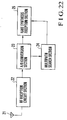
- the receiver shown in Fig. 22 is available, which is comprised of an antenna 21, RF reception circuit section 22, A/D (Analog/Digital) conversion section 23, multipath search section (multipath detection means) 24, and Rake synthesis reception section 25 for in-phase-synthesizing (Rake-synthesizing) a plurality of paths.
- A/D Analog/Digital
- multipath search section multipath detection means
- Rake synthesis reception section 25 for in-phase-synthesizing (Rake-synthesizing) a plurality of paths.
- the multipath search section 24 measures a delay profile (a signal power distribution with respect to delay times), selects several paths having high signal powers within the measurement range, and notifies the Rake synthesis reception section 25 of the timings of the paths.
- the Rake synthesis reception section 25 performs despreading in units of paths on the basis of the timing information, and performs Rake synthesis, thereby obtaining a path diversity effect.
- the Rake synthesis reception section 25 may have a means (path tracking means) for following the movement of an independently designated path.
- the multipath search section 24 must send path information to the Rake synthesis reception section 25 at least in an initial period or in predetermined cycles.
- This CDMA receiver and multipath search method are disclosed in Japanese Patent Laid-Open No. 9-181704 or the like.
- the multipath search section measures a delay profile, selects several paths having high signal powers within the measurement range, and notifies the Rake synthesis reception section of the timings of the paths.
- a delay profile contains a large quantity of data, and hence it takes time to search for peaks from all the data. For this reason, to search for several paths from the measured delay profile, maximum values corresponding to the number of paths to be searched out must be retrieved, or all the profile data must be sorted.
- a CDMA receiver comprising a Rake reception circuit for performing in-phase synthesis of reception signals from a plurality of paths, wherein a delay profile indicating a signal power distribution with respect to delay times of the reception signals is measured, an interference wave power value is estimated on the basis of the measured delay profile, valid data are extracted from the delay profile on the basis of the estimated interference wave power value, a plurality of correlation peak positions are detected from the extracted valid data, and path allocation to the Rake reception circuit is determined on the basis of the correlation peak positions.
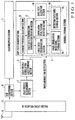
- Fig. 1 shows the arrangement of a Rake receiver according to the first embodiment of the present invention.
- the Rake receiver according to the first embodiment of the present invention is comprised of a DSP (Digital Signal Processor) 1 forming a path search section, delay profile measurement section 2, delay profile correlation value storage section 3 formed by a RAM (Random Access Memory) for temporarily storing delay profile data, antenna 4, RF reception circuit section 5, A/D (Analog/Digital) conversion section 6 for converting an analog signal into a digital signal, and a Rake reception section 7 for performing in-phase synthesis of reception signals from a plurality of paths.
- DSP Digital Signal Processor
- the DSP 1 includes an average power calculation section 11, valid data determination threshold calculation section 12, valid data determination section 13, internal storage section (RAM) 14 including a valid correlation data table storage section 15 and detected path table storage section 16, correlation peak position detection section 17, and Rake path allocation section 18.
- the DSP 1 operates under program control based on the programs stored in a control memory (not shown).
- a DSP dedicated to path searches need not always be used.
- this receiver may incorporate another function such as speech codec.
- the average power calculation section 11 of the DSP 1 calculates the average power of a delay profile.
- the valid data determination threshold calculation section 12 calculates a valid data threshold (interference wave power value) for checking whether the correlation data of a delay profile is data from a valid path.
- the valid data determination section 13 determines the valid data of a delay profile on the basis of the valid data determination threshold calculated by the valid data determination threshold calculation section 12, and selects only valid correlation data.
- the valid correlation data table storage section 15 temporarily stores the data selected by the valid data determination section 13.
- the correlation peak position detection section 17 detects the positions of a plurality of correlation peaks (paths).
- the detected path table storage section 16 stores the path positions detected by the correlation peak position detection section 17.
- the Rake path allocation section 18 determines path allocation to the Rake reception section 7.
- the analog signal received by the RF reception circuit section 5 through the antenna 4 is converted into digital data by the A/D conversion section 6.
- the delay profile measurement section 2 can be formed by a matched filter or sliding correlator.
- the delay profile measurement section 2 measures the delay time distribution (delay profile) of the correlation power values of despreading codes and reception data within a predetermined range.
- the average power calculation section 11 of the DSP 1 calculates the average power of delay profile data to average path changes due to fading.
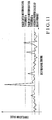
- Fig. 6 shows an example of the measured delay profile.
- the delay profile measured by the delay profile measurement section 2 is output to the delay profile correlation value storage section 3, and a message indicating the end of measurement is transmitted from the delay profile measurement section 2 to the DSP 1.
- the average power calculation section 11 of the DSP 1 averages the data of the delay profile obtained at intervals of delay times to obtain the average power value of the profile.
- correlation data corresponding to X despreading timings (delay times: abscissa) in the case shown in Fig. 6 are sampled, the sum total of the correlation data at the times 1 to X is divided by a sample count X.
- the average power calculation section 11 obtains an average delay profile power value like the one shown in Fig. 6.
- the valid data determination threshold calculation section 12 multiplies the average power calculated by the average power calculation section 11 by a predetermined value to absorb the variance of interference wave levels (portions having no correlation peaks). As shown in Fig. 6, a valid data determination threshold can be obtained by multiplying the average power by a coefficient (e.g., 1.5) that makes all the floor portions (interference wave power components) having low correlation values in the delay profile become equal to or smaller than the threshold. Note that the valid data determination threshold calculation section 12 can also calculate a valid data determination threshold by adding/subtracting the above coefficient to/from the average power or dividing it by the coefficient.
- a coefficient e.g. 1.5
- optimal data may be determined by acquiring delay profile data in an actual communication environment.
- a coefficient that changes in accordance with this delay profile averaging time may be used.
- the valid data determination section 13 writes the correlation values and phases of delay profile data equal to or larger than the valid data determination threshold in the valid correlation data table storage section 15.
- the correlation peak position detection section 17 detects a predetermined number of correlation peaks (multipath positions) from the valid correlation data stored in the valid correlation data table storage section 15, and writes the detected peaks in the detected path table storage section 16.
- the Rake path allocation section 18 allocates paths to the Rake reception section 7 on the basis of the path data stored in the detected path table storage section 16. For example, as a path allocation method, a method of designating a maximum of paths that can be Rake-synthesized to the Rake reception section 7 in descending order in magnitude is available. In this case, when only one path is detected, the Rake path allocation section 18 designates only the detected path even if the number of paths set is six. Note that the valid correlation data table storage section 15 and detected path table storage section 16 use the internal storage section 14 incorporated in the DSP 1.
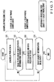
- Fig. 2 shows the operation of the DSP 1 in Fig. 1.
- the path search processing performed by the Rake receiver according to the first embodiment of the present invention will be described with reference to Figs. 1 and 2.
- the processing shown in Fig. 2 is implemented when the DSP 1 executes the programs stored in the control memory.
- the control memory may be set in the internal storage section 14. Alternatively, a ROM (Read-Only Memory), floppy disk, or the like may be used.
- the average power calculation section 11 of the DSP 1 Upon reception of a signal indicating the end of delay profile calculation from the delay profile measurement section 2 (step S1 in Fig. 2), the average power calculation section 11 of the DSP 1 calculates an average delay profile power (step S2 in Fig. 2).
- the valid data determination threshold calculation section 12 calculates a valid data determination threshold by multiplying the average power obtained by the average power calculation section 11 by a predetermined threshold coefficient (constant) (step S3 in Fig. 2).
- the valid data determination section 13 extracts data equal to or larger than the valid data determination threshold calculated by the valid data determination threshold calculation section 12 from the delay profile data, and stores the values and positions of the valid data in the valid correlation data table storage section 15 (step S4 in Fig. 2).
- the correlation peak position detection section 17 detects a predetermined number of correlation peaks from the data stored in the valid correlation data table storage section 15, and stores the magnitudes and positions of the corresponding paths in the detected path table storage section 16 (step S5 in Fig. 2).
- the Rake path allocation section 18 designates the path detected by the detected path to the Rake reception section 7 (step S6 in Fig. 2). Subsequently, the DSP 1 waits until a measurement end signal is received from the delay profile measurement section 2, and repeatedly performs the same processing as described above.
- Fig. 3 shows the processing performed by the valid data determination section 13 in Fig. 1.
- Fig. 3 shows an example of a processing cycle, together with the processing performed by the valid data determination section 13. The processing performed by the valid data determination section 13 will be described with reference to Fig. 1 and 3.
- the valid data determination section 13 loads correlation data one by one from the delay profile correlation value storage section 3 (step S11 in Fig. 3), and then checks whether the value of each data is equal to or larger than the valid data determination threshold (step S12 in Fig. 3).
- the valid data determination section 13 determines that the data is valid, and stores the value and position of the data in the valid correlation data table storage section 15 (step S13 in Fig. 3).
- the valid data determination section 13 repeatedly performs the above processing until determination on all delay profile data is completed (step S14 in Fig. 3). When determination on all the delay profile data is completed, the above processing is terminated.
- the approximate processing cycle count is 8 x delay profile sample count (the number of delay profile data), as shown in Fig. 3.
- Fig. 4 shows the processing performed by the correlation peak position detection section 17 in Fig. 1.
- Fig. 4 shows an example of a processing cycle, together with the processing performed by the correlation peak position detection section 17. The processing performed by the correlation peak position detection section 17 will be described with reference to Fig. 1 and 4.
- the correlation peak position detection section 17 performs maximum value retrieval to detect a plurality of peaks (step S21 in Fig. 4), and stores the maximum peak positions (step S22 in Fig. 4). The correlation peak position detection section 17 then masks the data at the detected peak positions (masks the data of the detected maximum peak portions with 0) (step S23 in Fig. 4).
- the correlation peak position detection section 17 removes the data at the detected peak positions by masking the data at the peak positions. Subsequently, the correlation peak position detection section 17 repeatedly performs the same processing as described above for the data at the remaining peak positions by a predetermined number of detected peaks (step S24 in Fig. 4).
- the approximate processing cycle count is 3 x retrieved data count x detected peak count, as shown in Fig. 4. In this case, a maximum value retrieval flow chart to be described later is used.
- Fig. 5 shows maximum value retrieval processing performed by the correlation peak position detection section 17 in Fig. 1.
- Fig. 5 shows an example of a processing cycle, together with the processing performed by the correlation peak position detection section 17.
- the maximum value retrieval processing performed by the correlation peak position detection section 17 will be described with reference to Figs. 1 and 5.
- the correlation peak position detection section 17 loads the initial maximum value (e.g., sets the value of the first data) and sets a retrieval start address (step S31 in Fig. 5). The correlation peak position detection section 17 then loads data from the valid correlation data table storage section 15 and advances the read address to the next data position (step S32 in Fig. 5).
- the initial maximum value e.g., sets the value of the first data
- the correlation peak position detection section 17 loads data from the valid correlation data table storage section 15 and advances the read address to the next data position (step S32 in Fig. 5).
- the correlation peak position detection section 17 compares the data loaded from the valid correlation data table storage section 15 with the maximum value data (step S33 in Fig. 5). If the data is larger than the maximum value (step S34 in Fig. 5), the correlation peak position detection section 17 replaces the maximum, value and stores the maximum value position in the detected path table storage section 16 (step S35 in Fig. 5).
- the correlation peak position detection section 17 repeatedly performs the same processing as described above until all retrieved data are compared with the maximum value (step S36 in Fig. 5).
- the approximate processing cycle count is 3 x retrieved data count, as shown in Fig. 5.
- total processing count ((9 + detected peak count/10) x delay profile data count)
- a processing count larger than that described above is required.
- the ratio of the above effective data to the delay profile data may be improved by only about 1/30 to 1/2.
- the insertion of validity determination can reduce the processing amount to about 1/2.
- the processing amount can be further reduced even if no peaks appear.
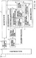
- Fig. 8 shows the arrangement of a Rake receiver according to the second embodiment of the present invention.
- the same reference numerals as in Fig. 1 denote the same parts in Fig. 8.
- the Rake receiver according to the second embodiment of the present invention has the same arrangement as that of the Rake receiver according to the first embodiment of the present invention except that a maximum value retrieval section 81 is arranged in a DSP 8 instead of the average power calculation section 11, and a valid data determination threshold calculation section 82 calculates a valid data determination threshold from the retrieval result obtained by the maximum value retrieval section 81.
- the operations of the same constituent elements as those of the Rake receiver according to the first embodiment of the present invention are the same as those thereof.
- the maximum value retrieval section 81 performs retrieves the maximum value of the correlation data loaded from a delay profile correlation value storage section 3 before a valid data determination section 13 performs validity determination.
- the valid data determination threshold calculation section 82 determines the value obtained by multiplying the maximum peak value retrieved by the maximum value retrieval section 81 by X (X is a predetermined ratio, e.g., 6 dB) as a valid data determination threshold. In this case, the valid data determination threshold calculation section 82 can calculate a valid data determination threshold by adding/subtracting the value X to/from the maximum peak value or dividing it by the value X like the valid data determination threshold calculation section 12 in Fig. 1.
- the valid data determination section 13 writes the correlation values and phases of delay profile data equal to or larger than the valid data determination threshold calculated by the valid data determination threshold calculation section 82 in a valid correlation data table storage section 15.
- a correlation peak position detection section 17 detects a predetermined number of correlation peaks (multipath positions) from the valid correlation data stored in the valid correlation data table storage section 15, and writes them in a detected path table storage section 16.
- a Rake path allocation section 18 allocates paths to a Rake reception section 7 on the basis of the path data stored in the detected path table storage section 16. This can improve the validity determination precision.
- Fig. 9 shows the processing performed by the DSP 8 in Fig. 8.
- the path search processing performed by the Rake receiver according to the second embodiment of the present invention will be described with reference to Figs. 8 and 9.
- the processing shown in Fig. 9 is implemented when the DSP 8 executes the programs stored in a control memory.
- the control memory may be set in an internal storage section 14. Alternatively, a ROM, floppy disk, or the like may be used.
- the maximum value retrieval section 81 of the DSP 8 retrieves the maximum value of the correlation data loaded from the delay profile correlation value storage section 3 before the valid data determination section 13 performs validity determination (step S42 in Fig. 9).
- the valid data determination threshold calculation section 82 calculates a valid data determination threshold by performing calculation (multiplication) for the maximum value retrieved by the maximum value retrieval section 81 using a predetermined threshold coefficient (constant) (step S43 in Fig. 9).
- the valid data determination section 13 extracts data equal to or larger than the valid data determination threshold calculated by the valid data determination threshold calculation section 82 from the delay profile data, and stores the values and positions of the valid data in the valid correlation data table storage section 15 (step S44 in Fig. 9).
- the correlation peak position detection section 17 detects a predetermined number of correlation peaks from the data stored in the valid correlation data table storage section 15, and stores the magnitudes and positions of the corresponding paths in the detected path table storage section 16 (step S45 in Fig. 9).
- the Rake path allocation section 18 designates the detected paths to the Rake reception section 7 (step S46 in Fig. 9). Subsequently, the DSP 8 waits until a measurement end signal is received from the delay profile measurement section 2, and repeatedly performs the above processing. Note that the maximum peak value retrieved by the maximum value retrieval section 81 is also used in the correlation peak position detection processing performed by the correlation peak position detection section 17.
- a more effective processing result can be obtained when noticeable peaks appear in a delay profile, as shown in Fig. 11, i.e., data in which peaks having larger correlation values than noise appear is measured, than when no noticeable peaks appear in a delay profile, as shown in Fig. 10, i.e., only data like noise can be measured.
- Fig. 12 shows the arrangement of a Rake receiver according to the third embodiment of the present invention.
- the same reference numerals as in Fig. 1 and 8 denote the same parts in Fig. 12.
- the Rake receiver according to the third embodiment has same arrangement as that of the Rake receiver according to the second embodiment of the present invention except that a DSP 8 additionally includes a valid data determination threshold calculation section 83 for checking, on the basis of the calculation result obtained by an average power calculation section 11 and the retrieval result obtained by a maximum value retrieval section 81, whether the correlation data of a delay profile is the data of a valid path.
- the operations of the same constituent elements as those of the Rake receiver according to the first embodiment of the present invention are the same as those thereof.
- the maximum value retrieval section 81 retrieves the maximum value of the correlation data loaded from a delay profile correlation value storage section 3 before a valid data determination section 13 performs validity determination.
- the valid data determination threshold calculation section 83 multiplies the average power calculated by the average power calculation section 11 by a predetermined value to absorb the variance of interference wave levels (portions having no correlation peaks), thereby obtaining a valid data determination threshold a .
- the valid data determination threshold calculation section 83 sets the value obtained by multiplying the maximum peak value retrieved by the maximum value retrieval section 81 by X (X is a predetermined ratio, e.g., 6 dB) as a valid data determination threshold b.
- the valid data determination section 13 can improve the validity determination precision by determining only data equal to or larger than these valid data determination threshold a or b as valid data.
- the valid data determination threshold calculation section 83 can calculate a valid data determination threshold by adding/subtracting the value X to/from the maximum peak value or dividing it by the value X like the valid data determination threshold calculation section 12 in Fig. 1.
- Fig. 13 shows the processing performed by the DSP 8 in Fig. 12.
- the path search processing performed by the Rake receiver according to the second embodiment of the present invention will be described with reference to Figs. 12 and 13.
- the processing shown in Fig. 13 can be implemented when the DSP 8 executes the programs stored in a control memory.
- the control memory may be set in an internal storage section 14. Alternatively, a ROM, floppy disk, or the like may be used.
- the average power calculation section 11 of the DSP 8 calculates an average delay profile power (step S52 in Fig. 13).
- the valid data determination threshold calculation section 83 performs calculation (multiplication) for the average power obtained by the average power calculation section 11 using a predetermined threshold coefficient (constant) to calculate the valid data determination threshold a (step S53 in Fig. 13).
- the maximum value retrieval section 81 of the DSP 8 retrieves the maximum value of the correlation data loaded from the delay profile correlation value storage section 3 before the valid data determination section 13 performs validity determination (step S54 in Fig. 13).
- the valid data determination threshold calculation section 83 performs calculation (multiplication) for the maximum value retrieved by the maximum value retrieval section 81 using a predetermined threshold coefficient (constant) to calculate the valid data determination threshold b (step S55 in Fig. 13).
- the valid data determination threshold calculation section 83 compares the calculated valid data determination thresholds a and b with each other. If valid data determination threshold a > valid data determination threshold b (step S56 in Fig. 13), the valid data determination threshold calculation section 83 determines the valid data determination threshold a as the final valid data determination threshold (step S57 in Fig. 13). If valid data determination threshold a ⁇ valid data determination threshold b (step S56 in Fig. 13), the valid data determination threshold calculation section 83 determines the valid data determination threshold b as the final valid data determination threshold (step S58 in Fig. 13).
- the valid data determination section 13 extracts data equal to or larger than the valid data determination threshold calculated by the valid data determination threshold calculation section 83 from the delay profile data, and stores the values and positions of the valid data in a valid correlation data table storage section 15 (step S59 in Fig. 13).
- the correlation peak position detection section 17 detects a predetermined number of correlation peaks from the data stored in the valid correlation data table storage section 15, and stores the magnitudes and positions of the corresponding paths in a detected path table storage section 16 (step S60 in Fig. 13).
- a Rake path allocation section 18 designates the detected paths to the Rake reception section 7 (step S61 in Fig. 13). Subsequently, the DSP 8 waits until a measurement end signal is received from the delay profile measurement section 2, and repeatedly performs the same processing as described above. Note that the maximum peak value retrieved by the maximum value retrieval section 81 is also used in the correlation peak position detection processing performed by the correlation peak position detection section 17.
- the third embodiment of the present invention can properly cope with both the case wherein no noticeable peaks appear in a delay profile, as shown in Fig. 10, i.e., only data like noise is measured, and the case wherein noticeable peaks appear in a delay profile, as shown in Fig. 11, i.e., data in which peaks having larger correlation values appear is measured.
- Fig. 14 shows the arrangement of a Rake receiver according to the fourth embodiment of the present invention.
- the same reference numerals as in Fig. 1 denote the same parts in Fig. 14.
- the Rake receiver according to the fourth embodiment of the present invention has the same arrangement as that of the Rake receiver according to the first embodiment of the present invention in Fig. 1 except that the allocation result obtained by a Rake path allocation section 18 is input to an average power calculation section 11 in a DSP 1.
- the operations of the same constituent elements as those of the Rake receiver according to the first embodiment of the present invention are the same as those thereof.
- the average power calculation section 11 subtracts the correlation data of the paths designed by the Rake path allocation section 18 from the sum total of the correlation data at times 1 to X, and divides the resultant value by "sample count X - designated path count".
- the average power calculation section 11 can obtain the average value of almost only noise components. If, therefore, a valid data determination threshold calculation section 12 calculates a valid data determination threshold on the basis of this average value, the valid data determination threshold precision can be improved. This makes it possible to detect paths that have been missed.
- Fig. 15 shows the processing performed by the DSP 1 in Fig. 14.
- the path search processing performed by the Rake receiver according to the fourth embodiment of the present invention will be described with reference to Figs. 14 and 15.
- the processing in Fig. 15 is implemented when the DSP 1 executes the programs stored in a control memory.
- the control memory may be set in the internal storage section 14. Alternatively, a ROM, floppy disk, or the like may be used.
- the average power calculation section 11 of the DSP 1 calculates the power value of a delay profile within a predetermined range, and compares the power value with a stored power value (calculated in advance) (step S72 in Fig. 15). If the difference between the currently calculated power value and the stored power value falls outside an allowable range (step S73 in Fig. 15), the average power calculation section 11 continuously calculates the average power of the delay profile (step S74 in Fig. 15).
- the valid data determination threshold calculation section 12 performs calculation (multiplication) for the average power obtained by the average power calculation section 11 using a predetermined threshold coefficient (constant) to calculate a valid data determination threshold (step S75 in Fig. 15).
- a valid data determination section 13 extracts data equal to or larger than the valid data determination threshold calculated by the valid data determination threshold calculation section 12 from the delay profile data, and stores the values and positions of the valid data in a valid correlation data table storage section 15 (step S76 in Fig. 15).
- a correlation peak position detection section 17 detects a predetermined number of correlation peaks from the data stored in the valid correlation data table storage section 15, and stores the magnitudes and positions of the corresponding paths in a detected path table storage section 16 (step S78 in Fig. 15).
- the Rake path allocation section 18 designates the detected paths to a Rake reception section 7 (step S79 in Fig. 15). Since the information of each path designated by the Rake path allocation section 18 is input to the average power calculation section 11, if a new threshold is calculated in the current processing (step S80 in Fig. 15), the correlation data of the path designated by the Rake path allocation section 18 is subtracted from the correlation data of all the addition results, and the resultant value is divided by "sample count - designated path count", thereby calculating an average value excluding the peak values of the allocated paths.
- the valid data determination threshold calculation section 12 performs calculation (multiplication) for the average power obtained by the average power calculation section 11 using a predetermined threshold coefficient (constant) to calculate a valid data determination threshold (step S81 in Fig. 15).
- the valid data determination threshold calculation section 12 then stores the calculated valid data determination threshold (step S82 in Fig. 15).
- the average power calculation section 11 interrupts calculation of the average power of a delay profile, and notifies the valid data determination threshold calculation section 12 that the valid data determination threshold used in the previous processing can be used. Upon reception of this notification, the valid data determination threshold calculation section 12 transmits the stored valid data determination threshold to the valid data determination section 13.
- the valid data determination section 13 extracts data equal to or larger than the valid data determination threshold stored in the valid data determination threshold calculation section 12, and stores the values and positions of the valid data in the valid correlation data table storage section 15 (step S77 in Fig. 15).
- the correlation peak position detection section 17 detects a predetermined number of correlation peaks from the data stored in the valid correlation data table storage section 15, and stores the magnitudes and positions of the corresponding paths in the detected path table storage section 16 (step S78 in Fig. 15).
- the Rake path allocation section 18 designates the detected paths to the Rake reception section 7 (step S79 in Fig. 15). Subsequently, the DSP 1 waits until a measurement end signal is received from the delay profile measurement section 2, and repeatedly performs the same-processing as described above.
- the processing time can be shortened. At this time, by stopping the supply of power to the delay profile measurement section 2 or the like, power can be saved.
- Fig. 16 shows the arrangement of a Rake receiver according to the fifth embodiment of the present invention.
- the same reference numerals as in Fig. 8 denote the same parts in Fig. 16.
- the Rake receiver according to the fifth embodiment of the present invention has the same arrangement as that of the Rake receiver according to the second embodiment of the present invention except that the allocation result obtained by a Rake path allocation section 18 is input to a maximum value retrieval section 81 in a DSP 8.
- the operations of the same constituent elements as those of the Rake receiver according to the second embodiment of the present invention are the same as those thereof.
- the maximum value retrieval section 81 Upon reception of the information of the paths designated by the Rake path allocation section 18, the maximum value retrieval section 81 calculates the power value of a delay profile within a predetermined range, and compares the calculated power value with a stored power value (previously calculated power value).
- the maximum value retrieval section 81 continues maximum value retrieval processing. If the difference falls within the allowable range, the maximum value retrieval section 81 interrupts the maximum value retrieval processing, and operates to extract valid data with the previously calculated valid data determination threshold.
- Fig. 17 shows the processing performed by the DSP 8 in Fig. 16.
- the path search processing performed by the Rake receiver according to the fifth embodiment of the present invention will be described with reference to Figs. 16 and 17.
- the processing in Fig. 17 is implemented when the DSP 8 executes the programs stored in a control memory.
- the control memory may be set in the internal storage section 14. Alternatively, a ROM, floppy disk, or the like may be used.
- the maximum value retrieval section 81 of the DSP 8 calculates the power value of a delay profile within a predetermined range, and compares the calculated power value with a stored power value (previously-calculated power value) (step S92 in Fig. 17).
- the maximum value retrieval section 81 continuously retrieves the maximum value of the correlation data loaded from the delay profile correlation value storage section 3 before a valid data determination section 13 performs validity determination (step S94 in Fig. 17).
- a valid data determination threshold calculation section 82 performs calculation (multiplication) for the maximum value retrieved by the maximum value retrieval section 81 using a predetermined threshold coefficient (constant) to calculate a valid data determination threshold (step S95 in Fig. 17).
- the valid data determination section 13 extracts data equal to or larger than the valid data determination threshold calculated by the valid data determination threshold calculation section 82 from the delay profile data, and stores the values and positions of the valid data in a valid correlation data table storage section 15 (step S96 in Fig. 17).
- a correlation peak position detection section 17 detects a predetermined number of correlation peaks from the data stored in the valid correlation data table storage section 15, and stores the magnitudes and positions of the corresponding paths in a detected path table storage section 16 (step S98 in Fig. 17).
- the Rake path allocation section 18 designates the detected paths to the Rake reception section 7 (step S99 in Fig. 17). Since the information of each path designated by the Rake path allocation section 18 is input to the maximum value retrieval section 81 at this time, if a new threshold is calculated by this processing (step S100 in Fig. 17), the valid data determination threshold calculated by the valid data determination threshold calculation section 82 is stored (step S101 in Fig. 17).
- the maximum value retrieval section 81 interrupts the retrieval of the maximum value of the delay profile, and notifies the valid data determination threshold calculation section 82 that the valid data determination threshold used in the previous processing can be used. Upon reception of this notification, the valid data determination threshold calculation section 82 sends the stored valid data determination threshold to the valid data determination section 13.
- the valid data determination section 13 extracts data equal to or larger than the valid data determination threshold stored in the valid data determination threshold calculation section 82 from the delay profile data, and stores the values and positions of the valid data in the valid correlation data table storage section 15 (step S97 in Fig. 17).
- the correlation peak position detection section 17 detects a predetermined number of correlation peaks from the data stored in the valid correlation data table storage section 15, and stores the magnitudes and positions of the corresponding paths in the detected path table storage section 16 (step S98 in Fig. 17).
- the Rake path allocation section 18 designates the detected paths to the Rake reception section 7 (step S99 in Fig. 17). Subsequently, the DSP 8 waits until a measurement end signal is received from the delay profile measurement section 2, and repeatedly performs the same processing as described above.
- the valid data determination threshold calculated by the previous processing is used. This can shorten the processing time. In this case, by stopping the supply of power to the delay profile measurement section 2, power can be saved.
- Fig. 18 shows the arrangement of a Rake receiver according to the sixth embodiment of the present invention.
- the same reference numerals as in Fig. 12 denote the same parts in Fig. 18.
- the arrangement of the Rake receiver according to the sixth embodiment of the present invention is the same as that of the Rake receiver according to the third embodiment of the present invention except that the allocation result obtained by a Rake path allocation section 18 is input to an average power calculation section 11 in a DSP 8.
- the operations of the same constituent elements as those of the Rake receiver according to the third embodiment of the present invention are the same as those thereof.
- the average power calculation section 11 subtracts the correlation data of the paths designed by the Rake path allocation section 18 from the sum total of the correlation data at times 1 to X, and divides the resultant value by "sample count X - designated path count".
- the average power calculation section 11 can obtain the average value of almost only noise components. If, therefore, a valid data determination threshold calculation section 12 calculates a valid data determination threshold on the basis of this average value, the valid data determination-threshold precision can be improved. This makes it possible to detect paths that have been missed.
- Figs. 19 and 20 show the processing performed by the DSP 8 in Fig. 18.
- the path search processing performed by the Rake receiver according to the sixth embodiment of the present invention will be described with reference to Figs. 18 and 20.
- the processing in Figs. 19 and 20 is implemented when the DSP 1 executes the programs stored in a control memory.
- the control memory may be set in the internal storage section 14. Alternatively, a ROM, floppy disk, or the like may be used.
- the average power calculation section 11 of the DSP 1 calculates the power value of a delay profile within a predetermined range, and compares the power value with a stored power value (calculated in advance) (step S112 in Fig. 19).
- step S113 in Fig. 19 If the difference between the currently calculated power value and the stored power value falls outside an allowable range (step S113 in Fig. 19), the average power calculation section 11 continuously calculates the average power of the delay profile (step S114 in Fig. 19).
- a valid data determination threshold calculation section 83 performs calculation (multiplication) for the average power obtained by the average power calculation section 11 using a predetermined threshold coefficient (constant) to calculate a valid data determination threshold a (step S115 in Fig. 19).
- a maximum value retrieval section 81 of the DSP 8 retrieves the maximum value of the correlation data loaded from a delay profile correlation value storage section 3 before a valid data determination section 13 performs validity determination (step S116 in Fig. 19).
- the valid data determination threshold calculation section 83 performs calculation (multiplication) for the maximum value retrieved by the maximum value retrieval section 81 using a predetermined threshold coefficient (constant) to calculate a valid data determination threshold b (step S117 in Fig. 19).
- the valid data determination threshold calculation section 83 compares the calculated valid data determination thresholds a and b with each other. If valid data determination threshold a > valid data determination threshold b (step S119 in Fig. 19), the valid data determination threshold calculation section 83 determines the valid data determination threshold a as the final valid data determination threshold (step S120 in Fig. 19). If valid data determination threshold a ⁇ valid data determination threshold b (step S119 in Fig. 19), the valid data determination threshold calculation section 83 determines the valid data determination threshold b as the final valid data determination threshold (step S121 in Fig. 19).
- the valid data determination section 13 extracts data equal to or larger than the valid data determination threshold calculated by the valid data determination threshold calculation section 83 from the delay profile data, and stores the values and positions of the valid data in a valid correlation data table storage section 15 (step S122 in Fig. 19).
- a correlation peak position detection section 17 detects a predetermined number of correlation peaks from the data stored in the valid correlation data table storage section 15, and stores the magnitudes and positions of the corresponding paths in a detected path table storage section 16 (step S123 in Fig. 19).
- the Rake path allocation section 18 designates the detected paths to a Rake reception section 7 (step S124 in Fig. 19). Since the information of each path designated by the Rake path allocation section 18 is input to the average power calculation section 11, if a new threshold is calculated by the current processing (step S125 in Fig. 20) and the new threshold is calculated on the basis of the average power (step S126 in Fig. 20), the correlation data of the paths designated by the Rake path allocation section 18 are subtracted from the sum total of all the correlation data calculated by the above processing, and the resultant value is divided by "sample count - designated path count", thereby calculating an average value excluding the peak values of the allocated paths.
- the valid data determination threshold calculation section 83 performs calculation (multiplication) for the average power obtained by the average power calculation section 11 using a predetermined threshold coefficient (constant) to calculate a valid data determination threshold (step S127 in Fig. 20), and stores the calculated valid data determination threshold (step S128 in Fig. 20).
- a new threshold is calculated by the current processing (step S125 in Fig. 20) and the new threshold is not calculated on the basis of the average power (step S126 in Fig. 20), i.e., if the threshold is obtained on the basis of the retrieval result obtained by the maximum value retrieval section 81, the threshold (used in the current processing) is stored (step S129 in Fig. 20).
- the average power calculation section 11 interrupts the calculation of the average power of the delay profile and retrieval of the maximum value of the delay profile, and notifies the valid data determination threshold calculation section 83 that the valid data determination threshold used in the previous processing can be used. Upon reception of this notification, the valid data determination threshold calculation section 83 sends the stored valid data determination threshold to the valid data determination section 13.
- the valid data determination section 13 extracts data equal to or larger than the valid data determination threshold stored in the valid data determination threshold calculation section 83 from the delay profile data, and stores the values and positions of the valid data in the valid correlation data table storage section 15 (step S118 in Fig. 19).
- the correlation peak position detection section 17 detects a predetermined number of correlation peaks from the data stored in the valid correlation data table storage section 15, and stores the magnitudes and positions of the corresponding paths in a detected path table storage section 16 (step S123 in Fig. 19).
- the Rake path allocation section 18 designates the detected paths to the Rake reception section 7 (step S124 in Fig. 19). Subsequently, the DSP 8 waits until a measurement end signal is received from the delay profile measurement section 2, and repeatedly performs the same processing as described above.
- the valid data determination threshold calculated by the previous processing is used. This can shorten the processing time. In this case, by stopping the supply of power to the delay profile measurement section 2, power can be saved.
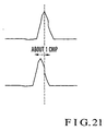
- Fig. 21 explains follow-up operation for changes in path delay time in the present invention.
- a finger is allocated to a delay profile correlation peak position (this operation changes depending on the path allocation algorithm to be used).
- the path allocated to the finger is regarded as a valid path, and the timing is updated to the position at which the path is detected. This can improve the follow-up characteristics with respect to changes in path delay time.
- the valid data determination threshold calculation section 12 or 83 calculates a valid data determination threshold for determining the validity of the correlation data of a delay profile on the basis of the calculation result obtained by the average power calculation section 11, or the valid data determination threshold calculation section 82 or 83 calculates a valid data determination threshold for determining the validity of the correlation data of the delay profile on the basis of the retrieval result obtained by the maximum value retrieval section 81.
- the valid data determination section 13 determines valid data of the delay profile file on the basis of the valid data determination threshold, thereby reducing the number of data to be calculated. This can greatly reduces the processing amounts in the DSPs (path search sections) 1 and 8.
- the DSPs 1 and 8 Since the processing amount in the DSPs 1 and 8 can be reduced, the DSPs 1 and 8 can be operated at a low-frequency clock, and the current consumption can be reduced.
- the processing amounts in the DSPs 1 and 8 can be reduced, and the path search function can be incorporated in a speech codec DSP or communication control CPU. This can simplify the hardware arrangement.
- each embodiment has been described above in relation to the processing for the reception signal from one base station.
- a CDMA receiver processes reception signals from a plurality of base stations, and hence the above processing may be performed for each reception signal from each base station upon soft handover or the like.
- each circuit described above may be provided for each base station or may be shared among base stations.
Landscapes
- Engineering & Computer Science (AREA)
- Computer Networks & Wireless Communication (AREA)
- Signal Processing (AREA)
- Mobile Radio Communication Systems (AREA)
- Noise Elimination (AREA)
Applications Claiming Priority (2)
| Application Number | Priority Date | Filing Date | Title |
|---|---|---|---|
| JP26932898 | 1998-09-24 | ||
| JP26932898A JP3031351B2 (ja) | 1998-09-24 | 1998-09-24 | Cdma受信装置及びそれに用いるパス検出方法並びにその制御プログラムを記録した記録媒体 |
Publications (3)
| Publication Number | Publication Date |
|---|---|
| EP0989685A2 true EP0989685A2 (de) | 2000-03-29 |
| EP0989685A3 EP0989685A3 (de) | 2004-11-03 |
| EP0989685B1 EP0989685B1 (de) | 2008-07-30 |
Family
ID=17470839
Family Applications (1)
| Application Number | Title | Priority Date | Filing Date |
|---|---|---|---|
| EP19990118040 Expired - Lifetime EP0989685B1 (de) | 1998-09-24 | 1999-09-22 | CDMA Rake-Empfänger und Vorrichtung |
Country Status (5)
| Country | Link |
|---|---|
| US (1) | US6768729B1 (de) |
| EP (1) | EP0989685B1 (de) |
| JP (1) | JP3031351B2 (de) |
| AU (1) | AU760220B2 (de) |
| DE (1) | DE69939202D1 (de) |
Cited By (17)
| Publication number | Priority date | Publication date | Assignee | Title |
|---|---|---|---|---|
| GB2346780A (en) * | 1998-12-10 | 2000-08-16 | Nec Corp | Power control in a CDMA receiver having RAKE fingers |
| EP1143633A2 (de) * | 2000-04-06 | 2001-10-10 | NTT DoCoMo, Inc. | Vorrichtung und Verfahren zur Erfassung der Kommunikationsqualität |
| EP1235363A1 (de) * | 2000-09-29 | 2002-08-28 | Matsushita Electric Industrial Co., Ltd. | Drahtlose empfangsvorrichtung und verfahren zur bestimmung der verzögerungsdifferenz zwischen empfangszweigen in drahtloser empfangsvorrichtung |
| GB2375024A (en) * | 2001-01-15 | 2002-10-30 | Nec Corp | CDMA receiver divides a delay profile into regions and meaures the power in each region, with regions of higher power being measured more frequently |
| EP1286475A2 (de) * | 2001-08-22 | 2003-02-26 | Nec Corporation | CDMA-Empfänger, Pfadsuchverfahren und Programm |
| EP1289161A2 (de) * | 2001-08-30 | 2003-03-05 | Nec Corporation | Vorrichtung zur Mehrwegerkennung in einem CDMA-Empfänger |
| EP1304814A2 (de) * | 2001-10-19 | 2003-04-23 | Nec Corporation | CDMA-Empfänger und Verfahren zur Wegeauswahl |
| EP1339172A1 (de) * | 2000-11-09 | 2003-08-27 | NEC Corporation | Rake-empfängervorrichtung und empfangsverfahren |
| EP1398884A1 (de) * | 2002-09-13 | 2004-03-17 | Telefonaktiebolaget L M Ericsson (Publ) | Ablaufsteurungsverfahren für Wegsucher |
| WO2004025859A1 (en) * | 2002-09-13 | 2004-03-25 | Telefonaktiebolaget Lm Ericsson (Publ) | Method for path-seacher scheduling |
| WO2004028017A1 (en) * | 2002-09-18 | 2004-04-01 | Telefonaktiebolaget Lm Ericsson (Publ) | Robust delay estimation architecture |
| EP1447914A1 (de) * | 2003-02-05 | 2004-08-18 | Infineon Technologies AG | Erfassung von Datenübertragungspfaden |
| US6912243B1 (en) | 2000-01-19 | 2005-06-28 | Mitsubishi Denki Kabushiki Kaisha | Spread spectrum receiver and spread spectrum receiving method |
| EP1729426A2 (de) * | 2001-02-14 | 2006-12-06 | NEC Corporation | Mobilkommunikationssystem, Basisstation und Kommunikationssteuerverfahren |
| CN100342662C (zh) * | 2001-04-18 | 2007-10-10 | 日本电气株式会社 | 码分多址接收设备和路径保护方法 |
| CN100411333C (zh) * | 2001-10-19 | 2008-08-13 | 诺基亚有限公司 | 用于控制从包含至少一个数据分组的数据流中提取数据的方法和设备 |
| US7474648B2 (en) | 2003-06-18 | 2009-01-06 | Telefonaktiebolaget L M Ericsson (Publ) | Filtering multipath propagation delay values for use in a mobile communications system |
Families Citing this family (36)
| Publication number | Priority date | Publication date | Assignee | Title |
|---|---|---|---|---|
| US6396819B1 (en) | 1998-03-21 | 2002-05-28 | Richard D. Fleeter | Low-cost satellite communication system |
| JP3367475B2 (ja) * | 1999-07-06 | 2003-01-14 | 日本電気株式会社 | 無線通信機および無線通信機の消費電力制御方法 |
| JP3468189B2 (ja) | 2000-02-02 | 2003-11-17 | 日本電気株式会社 | パターン生成回路及びそれを用いたマルチパス検出回路並びにそのマルチパス検出方法 |
| US7227884B2 (en) | 2000-02-28 | 2007-06-05 | Aeroastro, Inc. | Spread-spectrum receiver with progressive fourier transform |
| EP1195914B1 (de) * | 2000-07-03 | 2007-03-14 | Mitsubishi Denki Kabushiki Kaisha | Vorrichtung und verfahren zur korrektur der zeitgabe |
| JP2002026768A (ja) * | 2000-07-07 | 2002-01-25 | Nec Corp | 通信装置 |
| JP3421314B2 (ja) * | 2000-10-04 | 2003-06-30 | 松下電器産業株式会社 | パス選択装置及びパス選択方法 |
| JP4818568B2 (ja) * | 2000-12-04 | 2011-11-16 | 三菱電機株式会社 | 合成受信方法および合成受信装置 |
| JP4558225B2 (ja) * | 2001-02-15 | 2010-10-06 | 株式会社日立国際電気 | 符号分割多重アクセス受信機 |
| JP3970565B2 (ja) * | 2001-09-12 | 2007-09-05 | 富士通株式会社 | 受信装置、受信方法、および、半導体装置 |
| JP3588089B2 (ja) * | 2002-05-22 | 2004-11-10 | 松下電器産業株式会社 | Cdma受信装置、移動局装置及び基地局装置 |
| JP3879595B2 (ja) * | 2002-06-19 | 2007-02-14 | 日本電気株式会社 | Cdma復調回路及びそれに用いるcdma移動体通信復調方法 |
| JP4012444B2 (ja) * | 2002-08-06 | 2007-11-21 | 松下電器産業株式会社 | 遅延プロファイル作成方法および遅延プロファイル作成装置 |
| US7197063B2 (en) * | 2002-09-18 | 2007-03-27 | Telefonaktiebolaget Lm Ericsson (Publ) | Advanced rake delay control |
| US7072635B2 (en) * | 2002-10-08 | 2006-07-04 | Freescale Semiconductor, Inc. | Method for combining data from phase indeterminate data streams for raking |
| JP4123364B2 (ja) * | 2003-02-07 | 2008-07-23 | 日本電気株式会社 | Cdma受信装置 |
| JP3675446B2 (ja) * | 2003-03-26 | 2005-07-27 | 日本電気株式会社 | Cdma受信装置、そのパス管理方法、及びパス管理プログラム |
| US7212591B2 (en) * | 2003-04-28 | 2007-05-01 | Telefonaktiebolaget Lm Ericsson (Publ) | Methods and receivers that estimate multi-path delays by removing signal rays from a power-delay profile |
| JP3943062B2 (ja) * | 2003-08-25 | 2007-07-11 | シャープ株式会社 | Cdma受信装置、cdma受信方法、cdma受信プログラム、及び、プログラム記録媒体 |
| KR100532062B1 (ko) * | 2003-12-27 | 2006-01-09 | 한국전자통신연구원 | 다중 채널 통신 시스템의 적응형 자원 할당 장치 및 그 방법 |
| KR20050118596A (ko) * | 2004-06-14 | 2005-12-19 | 삼성전자주식회사 | 위성 디지털 멀티미디어 방송 시스템의 수신기에서 전력소모 감소 방법 및 장치 |
| JP4389704B2 (ja) * | 2004-07-16 | 2009-12-24 | 日本電気株式会社 | Cdma受信装置、およびcdma受信装置における同期タイミング検出方法 |
| JP2006101308A (ja) * | 2004-09-30 | 2006-04-13 | Fujitsu Ltd | 無線基地局装置及びパスサーチ方法 |
| JP2006135420A (ja) * | 2004-11-02 | 2006-05-25 | Matsushita Electric Ind Co Ltd | 受信装置及びパスサーチ方法 |
| US8594151B2 (en) * | 2005-10-31 | 2013-11-26 | Nokia Corporation | Pilot sequence detection |
| WO2007136415A2 (en) * | 2005-12-30 | 2007-11-29 | Comtech Mobile Datacom Corporation | Mobile satellite communications |
| JP2008124942A (ja) * | 2006-11-15 | 2008-05-29 | Nec Corp | 無線通信システム、無線通信装置及びそれらに用いる有効パス検出方法 |
| US8275080B2 (en) * | 2006-11-17 | 2012-09-25 | Comtech Mobile Datacom Corporation | Self-supporting simplex packets |
| JP5231762B2 (ja) * | 2007-07-02 | 2013-07-10 | 富士通株式会社 | 受信機及び受信処理方法 |
| US8284749B2 (en) * | 2008-03-10 | 2012-10-09 | Comtech Mobile Datacom Corporation | Time slot synchronized, flexible bandwidth communication system |
| US8064551B2 (en) * | 2008-04-11 | 2011-11-22 | Comtech Mobile Datacom Corporation | Determining burst transmission signals |
| US8548107B1 (en) | 2009-01-26 | 2013-10-01 | Comtech Mobile Datacom Corporation | Advanced multi-user detector |
| US9106364B1 (en) | 2009-01-26 | 2015-08-11 | Comtech Mobile Datacom Corporation | Signal processing of a high capacity waveform |
| US8675711B1 (en) | 2009-09-25 | 2014-03-18 | Comtech Mobile Datacom Corporation | System and methods for dynamic spread spectrum usage |
| US8225252B2 (en) * | 2010-06-25 | 2012-07-17 | Intel Corporation | Systems, methods, apparatus and computer readable mediums for use in association with systems having interference |
| CN102769893B (zh) * | 2011-05-06 | 2017-09-22 | 深圳市中兴微电子技术有限公司 | 一种峰值搜索方法及装置 |
Citations (2)
| Publication number | Priority date | Publication date | Assignee | Title |
|---|---|---|---|---|
| EP0756387A2 (de) * | 1995-07-25 | 1997-01-29 | Nokia Mobile Phones Ltd. | Serielle Erfassungseinrichtung mit anpassbarem Schwellenwert und optimaler Entscheidung für eine Spreizspektrumanordnung |
| EP0794627A2 (de) * | 1996-03-05 | 1997-09-10 | SHARP Corporation | Spreizspektrumübertragungsgerät |
Family Cites Families (15)
| Publication number | Priority date | Publication date | Assignee | Title |
|---|---|---|---|---|
| JPH07231278A (ja) | 1994-02-18 | 1995-08-29 | Fujitsu Ltd | 直接拡散スペクトル拡散通信方式によるレイク受信機 |
| JP2605648B2 (ja) * | 1994-12-22 | 1997-04-30 | 日本電気株式会社 | Ss受信機における逆拡散符号位相検出装置 |
| JP3745430B2 (ja) | 1995-12-22 | 2006-02-15 | 株式会社エヌ・ティ・ティ・ドコモ | Cdmaマルチパス・サーチ方法及びcdma信号受信装置 |
| JP2820918B2 (ja) * | 1996-03-08 | 1998-11-05 | 株式会社ワイ・アール・ピー移動通信基盤技術研究所 | スペクトル拡散通信装置 |
| JP3358170B2 (ja) | 1996-07-24 | 2002-12-16 | 株式会社エヌ・ティ・ティ・ドコモ | Cdma無線通信の受信方法 |
| JP3190268B2 (ja) | 1996-09-20 | 2001-07-23 | 沖電気工業株式会社 | Rake受信装置 |
| JP3103311B2 (ja) | 1996-10-03 | 2000-10-30 | 国際電気株式会社 | Rake受信機 |
| JPH10145326A (ja) | 1996-11-14 | 1998-05-29 | Fujitsu Ltd | Cdmaシステム用受信装置 |
| JPH10164011A (ja) | 1996-11-29 | 1998-06-19 | Matsushita Electric Ind Co Ltd | スペクトル拡散通信装置 |
| JPH10173630A (ja) * | 1996-12-13 | 1998-06-26 | Nec Corp | Cdmaチップ同期回路 |
| JP3228405B2 (ja) | 1996-12-25 | 2001-11-12 | 株式会社エヌ・ティ・ティ・ドコモ | 直接拡散cdma伝送方式の受信機 |
| JP2924864B2 (ja) | 1997-06-16 | 1999-07-26 | 日本電気株式会社 | 適応レイク受信方式 |
| JP2870526B1 (ja) * | 1997-09-04 | 1999-03-17 | 日本電気株式会社 | Cdma受信装置 |
| US6229842B1 (en) * | 1998-07-16 | 2001-05-08 | Telefonaktiebolaget Lm Ericsson (Publ) | Adaptive path selection threshold setting for DS-CDMA receivers |
| US6373882B1 (en) * | 1998-11-06 | 2002-04-16 | Telefonaktiebolaget Lm Ericsson (Publ) | Motion estimator for a CDMA mobile station |
-
1998
- 1998-09-24 JP JP26932898A patent/JP3031351B2/ja not_active Expired - Fee Related
-
1999
- 1999-09-22 EP EP19990118040 patent/EP0989685B1/de not_active Expired - Lifetime
- 1999-09-22 DE DE69939202T patent/DE69939202D1/de not_active Expired - Lifetime
- 1999-09-23 AU AU50104/99A patent/AU760220B2/en not_active Ceased
- 1999-09-23 US US09/404,703 patent/US6768729B1/en not_active Expired - Lifetime
Patent Citations (2)
| Publication number | Priority date | Publication date | Assignee | Title |
|---|---|---|---|---|
| EP0756387A2 (de) * | 1995-07-25 | 1997-01-29 | Nokia Mobile Phones Ltd. | Serielle Erfassungseinrichtung mit anpassbarem Schwellenwert und optimaler Entscheidung für eine Spreizspektrumanordnung |
| EP0794627A2 (de) * | 1996-03-05 | 1997-09-10 | SHARP Corporation | Spreizspektrumübertragungsgerät |
Non-Patent Citations (2)
| Title |
|---|
| SANGUOON CHUNG: "A new serial search acquisition approach with automatic decision threshold control" VEHICULAR TECHNOLOGY CONFERENCE, 1995 IEEE 45TH CHICAGO, IL, USA 25-28 JULY 1995, NEW YORK, NY, USA,IEEE, US, 25 July 1995 (1995-07-25), pages 530-536, XP010166999 ISBN: 0-7803-2742-X * |
| SHI Z-L ET AL: "Automated threshold control for acquisition in spread spectrum packet radio communication" PROCEEDINGS OF THE INTERNATIONAL CONFERENCE ON COMMUNICATIONS (ICC). GENEVA, MAY 23 - 26, 1993, NEW YORK, IEEE, US, vol. VOL. 3, 23 May 1993 (1993-05-23), pages 478-482, XP010136947 ISBN: 0-7803-0950-2 * |
Cited By (41)
| Publication number | Priority date | Publication date | Assignee | Title |
|---|---|---|---|---|
| US6628698B1 (en) | 1998-12-10 | 2003-09-30 | Nec Corporation | CDMA reception apparatus and power control method therefor |
| GB2346780A (en) * | 1998-12-10 | 2000-08-16 | Nec Corp | Power control in a CDMA receiver having RAKE fingers |
| GB2346780B (en) * | 1998-12-10 | 2004-04-07 | Nec Corp | CDMA reception apparatus and power control method therefor |
| AU765920B2 (en) * | 1998-12-10 | 2003-10-02 | Lenovo Innovations Limited (Hong Kong) | CDMA reception apparatus and power control method therefor |
| US6912243B1 (en) | 2000-01-19 | 2005-06-28 | Mitsubishi Denki Kabushiki Kaisha | Spread spectrum receiver and spread spectrum receiving method |
| SG105494A1 (en) * | 2000-04-06 | 2004-08-27 | Ntt Docomo Inc | Apparatus and method for acquisition of communication quality |
| US7545790B2 (en) | 2000-04-06 | 2009-06-09 | Ntt Docomo, Inc. | Apparatus and method for acquisition of communication quality |
| EP1143633A3 (de) * | 2000-04-06 | 2003-02-19 | NTT DoCoMo, Inc. | Vorrichtung und Verfahren zur Erfassung der Kommunikationsqualität |
| US6968197B2 (en) | 2000-04-06 | 2005-11-22 | Ntt Docomo, Inc. | Apparatus and method for acquisition of communication quality |
| EP1143633A2 (de) * | 2000-04-06 | 2001-10-10 | NTT DoCoMo, Inc. | Vorrichtung und Verfahren zur Erfassung der Kommunikationsqualität |
| EP1235363A1 (de) * | 2000-09-29 | 2002-08-28 | Matsushita Electric Industrial Co., Ltd. | Drahtlose empfangsvorrichtung und verfahren zur bestimmung der verzögerungsdifferenz zwischen empfangszweigen in drahtloser empfangsvorrichtung |
| EP1235363A4 (de) * | 2000-09-29 | 2010-05-05 | Panasonic Corp | Drahtlose empfangsvorrichtung und verfahren zur bestimmung der verzögerungsdifferenz zwischen empfangszweigen in drahtloser empfangsvorrichtung |
| EP1339172A1 (de) * | 2000-11-09 | 2003-08-27 | NEC Corporation | Rake-empfängervorrichtung und empfangsverfahren |
| US7248619B2 (en) | 2000-11-09 | 2007-07-24 | Nec Corporation | Rake receiver and receiving method |
| EP1339172A4 (de) * | 2000-11-09 | 2007-05-16 | Nec Corp | Rake-empfängervorrichtung und empfangsverfahren |
| US7254162B2 (en) | 2001-01-15 | 2007-08-07 | Nec Corporation | CDMA receiver performing a path search, path search method, and program therefor |
| GB2375024A (en) * | 2001-01-15 | 2002-10-30 | Nec Corp | CDMA receiver divides a delay profile into regions and meaures the power in each region, with regions of higher power being measured more frequently |
| GB2375024B (en) * | 2001-01-15 | 2003-04-16 | Nec Corp | CDMA receiver,method of operation and program therefor |
| EP1729426A2 (de) * | 2001-02-14 | 2006-12-06 | NEC Corporation | Mobilkommunikationssystem, Basisstation und Kommunikationssteuerverfahren |
| US7738889B2 (en) | 2001-02-14 | 2010-06-15 | Nec Corporation | Mobile communication system, base station, and communication control method |
| EP1729426A3 (de) * | 2001-02-14 | 2007-07-25 | NEC Corporation | Mobilkommunikationssystem, Basisstation und Kommunikationssteuerverfahren |
| CN100342662C (zh) * | 2001-04-18 | 2007-10-10 | 日本电气株式会社 | 码分多址接收设备和路径保护方法 |
| EP1286475A2 (de) * | 2001-08-22 | 2003-02-26 | Nec Corporation | CDMA-Empfänger, Pfadsuchverfahren und Programm |
| US7039097B2 (en) | 2001-08-22 | 2006-05-02 | Nec Corporation | CDMA receiver, path search method and program |
| EP1286475A3 (de) * | 2001-08-22 | 2003-12-10 | Nec Corporation | CDMA-Empfänger, Pfadsuchverfahren und Programm |
| EP1289161A2 (de) * | 2001-08-30 | 2003-03-05 | Nec Corporation | Vorrichtung zur Mehrwegerkennung in einem CDMA-Empfänger |
| US7133436B2 (en) | 2001-08-30 | 2006-11-07 | Nec Electronics Corporation | Path detection apparatus in CDMA reception device |
| EP1289161A3 (de) * | 2001-08-30 | 2003-10-08 | NEC Electronics Corporation | Vorrichtung zur Mehrwegerkennung in einem CDMA-Empfänger |
| EP1438803B2 (de) † | 2001-10-19 | 2009-04-29 | Nokia Corporation | Verfahren und einrichtung zur steuerung der datenextraktion aus einem datenstrom, der mindestens ein datenpaket enthält |
| EP1304814A3 (de) * | 2001-10-19 | 2004-02-11 | Nec Corporation | CDMA-Empfänger und Verfahren zur Wegeauswahl |
| CN100411333C (zh) * | 2001-10-19 | 2008-08-13 | 诺基亚有限公司 | 用于控制从包含至少一个数据分组的数据流中提取数据的方法和设备 |
| EP1304814A2 (de) * | 2001-10-19 | 2003-04-23 | Nec Corporation | CDMA-Empfänger und Verfahren zur Wegeauswahl |
| US7646831B2 (en) * | 2001-10-19 | 2010-01-12 | Nokia Corporation | Method and a device for controlling data extraction from a data stream containing at lease one data packet |
| WO2004025859A1 (en) * | 2002-09-13 | 2004-03-25 | Telefonaktiebolaget Lm Ericsson (Publ) | Method for path-seacher scheduling |
| EP1398884A1 (de) * | 2002-09-13 | 2004-03-17 | Telefonaktiebolaget L M Ericsson (Publ) | Ablaufsteurungsverfahren für Wegsucher |
| US7555077B2 (en) | 2002-09-13 | 2009-06-30 | Telefonaktiebolaget L M Ericsson (Publ) | Method for path-searcher scheduling |
| US7142586B2 (en) | 2002-09-18 | 2006-11-28 | Telefonaktiebolaget Lm Ericsson (Publ) | Robust delay estimation architecture |
| WO2004028017A1 (en) * | 2002-09-18 | 2004-04-01 | Telefonaktiebolaget Lm Ericsson (Publ) | Robust delay estimation architecture |
| US7313171B2 (en) | 2003-02-05 | 2007-12-25 | Infineon Technologies Ag | Apparatus for data transmission path detection |
| EP1447914A1 (de) * | 2003-02-05 | 2004-08-18 | Infineon Technologies AG | Erfassung von Datenübertragungspfaden |
| US7474648B2 (en) | 2003-06-18 | 2009-01-06 | Telefonaktiebolaget L M Ericsson (Publ) | Filtering multipath propagation delay values for use in a mobile communications system |
Also Published As
| Publication number | Publication date |
|---|---|
| AU5010499A (en) | 2000-03-30 |
| DE69939202D1 (de) | 2008-09-11 |
| US6768729B1 (en) | 2004-07-27 |
| EP0989685B1 (de) | 2008-07-30 |
| JP2000101549A (ja) | 2000-04-07 |
| AU760220B2 (en) | 2003-05-08 |
| EP0989685A3 (de) | 2004-11-03 |
| JP3031351B2 (ja) | 2000-04-10 |
Similar Documents
| Publication | Publication Date | Title |
|---|---|---|
| EP0989685A2 (de) | CDMA Rake-Empfänger | |
| US6795422B2 (en) | Method of providing hysteresis in detection of path timing by multiplying delay profile by weighting coefficient | |
| US6731622B1 (en) | Multipath propagation delay determining means using periodically inserted pilot symbols | |
| CA2342158C (en) | Adaptive path selection threshold setting for ds-cdma receivers | |
| KR100694927B1 (ko) | 주기적으로 삽입되는 파일럿 기호를 사용하는 다중 경로전파 지연 결정 장치 | |
| EP1543634B1 (de) | Bewertung der mehrstreckenverzögerungsschätzungsqualität mittels interferenzschätzungen | |
| KR100701002B1 (ko) | 상관 후 전처리한 소프트 임계값을 이용한 수신 cdma신호의 전력 측정 | |
| KR100668590B1 (ko) | 확산 스펙트럼 신호의 신속하고 정확한 식별 | |
| KR100384097B1 (ko) | 개선된 경로 타이밍 검출 방법 및 그것을 이용한 cdma수신 장치 | |
| EP1209818A1 (de) | Methode und Schaltungsanordnung zur Mehrwegerkennung für einen CDMA-Empfänger | |
| KR100458665B1 (ko) | Cdma 수신기, 경로 검색 방법 및 이를 실행하는프로그램이 기억되어 있는 컴퓨터 판독가능 기억매체 | |
| JP3322253B2 (ja) | Cdma受信装置及びそれに用いるパス検出方法並びにその制御プログラムを記録した記録媒体 | |
| JP3440919B2 (ja) | マルチパス検出回路 | |
| EP1107467A2 (de) | Drahtloses Kommunikationsgerät und -verfahren zum Vorhersagen einer Rahmenrate in einem CDMA Kommunikationssystem | |
| US7372897B2 (en) | Portable information communication terminal, program, and recording medium | |
| JP3292186B2 (ja) | Cdma受信装置及びそのマルチパスのフィンガ割り当て方法並びにその制御プログラムを記録した記録媒体 | |
| JP4515618B2 (ja) | 移動通信端末 | |
| JP2005354263A (ja) | 受信装置及び受信装置におけるパス選択方法 | |
| JP2003318780A (ja) | パス補足方法及びこの方法を利用するcdma受信装置 |
Legal Events
| Date | Code | Title | Description |
|---|---|---|---|
| PUAI | Public reference made under article 153(3) epc to a published international application that has entered the european phase |
Free format text: ORIGINAL CODE: 0009012 |
|
| AK | Designated contracting states |
Kind code of ref document: A2 Designated state(s): AT BE CH CY DE DK ES FI FR GB GR IE IT LI LU MC NL PT SE |
|
| AX | Request for extension of the european patent |
Free format text: AL;LT;LV;MK;RO;SI |
|
| PUAL | Search report despatched |
Free format text: ORIGINAL CODE: 0009013 |
|
| AK | Designated contracting states |
Kind code of ref document: A3 Designated state(s): AT BE CH CY DE DK ES FI FR GB GR IE IT LI LU MC NL PT SE |
|
| AX | Request for extension of the european patent |
Extension state: AL LT LV MK RO SI |
|
| 17P | Request for examination filed |
Effective date: 20041006 |
|
| 17Q | First examination report despatched |
Effective date: 20050317 |
|
| AKX | Designation fees paid |
Designated state(s): DE FR GB |
|
| RTI1 | Title (correction) |
Free format text: CDMA RAKE RECEIVER AND METHOD THEREOF |
|
| GRAP | Despatch of communication of intention to grant a patent |
Free format text: ORIGINAL CODE: EPIDOSNIGR1 |
|
| GRAS | Grant fee paid |
Free format text: ORIGINAL CODE: EPIDOSNIGR3 |
|
| GRAA | (expected) grant |
Free format text: ORIGINAL CODE: 0009210 |
|
| AK | Designated contracting states |
Kind code of ref document: B1 Designated state(s): DE FR GB |
|
| REG | Reference to a national code |
Ref country code: GB Ref legal event code: FG4D |
|
| REF | Corresponds to: |
Ref document number: 69939202 Country of ref document: DE Date of ref document: 20080911 Kind code of ref document: P |
|
| PLBE | No opposition filed within time limit |
Free format text: ORIGINAL CODE: 0009261 |
|
| STAA | Information on the status of an ep patent application or granted ep patent |
Free format text: STATUS: NO OPPOSITION FILED WITHIN TIME LIMIT |
|
| 26N | No opposition filed |
Effective date: 20090506 |
|
| REG | Reference to a national code |
Ref country code: GB Ref legal event code: 732E Free format text: REGISTERED BETWEEN 20141023 AND 20141029 |
|
| REG | Reference to a national code |
Ref country code: FR Ref legal event code: TP Owner name: LENOVO INNOVATIONS LIMITED (HONG KONG), HK Effective date: 20141119 |
|
| REG | Reference to a national code |
Ref country code: FR Ref legal event code: PLFP Year of fee payment: 18 |
|
| PGFP | Annual fee paid to national office [announced via postgrant information from national office to epo] |
Ref country code: GB Payment date: 20160921 Year of fee payment: 18 Ref country code: DE Payment date: 20160913 Year of fee payment: 18 |
|
| PGFP | Annual fee paid to national office [announced via postgrant information from national office to epo] |
Ref country code: FR Payment date: 20160816 Year of fee payment: 18 |
|
| REG | Reference to a national code |
Ref country code: DE Ref legal event code: R119 Ref document number: 69939202 Country of ref document: DE |
|
| GBPC | Gb: european patent ceased through non-payment of renewal fee |
Effective date: 20170922 |
|
| REG | Reference to a national code |
Ref country code: FR Ref legal event code: ST Effective date: 20180531 |
|
| PG25 | Lapsed in a contracting state [announced via postgrant information from national office to epo] |
Ref country code: DE Free format text: LAPSE BECAUSE OF NON-PAYMENT OF DUE FEES Effective date: 20180404 Ref country code: GB Free format text: LAPSE BECAUSE OF NON-PAYMENT OF DUE FEES Effective date: 20170922 |
|
| PG25 | Lapsed in a contracting state [announced via postgrant information from national office to epo] |
Ref country code: FR Free format text: LAPSE BECAUSE OF NON-PAYMENT OF DUE FEES Effective date: 20171002 |