EP1143633A2 - Vorrichtung und Verfahren zur Erfassung der Kommunikationsqualität - Google Patents
Vorrichtung und Verfahren zur Erfassung der Kommunikationsqualität Download PDFInfo
- Publication number
- EP1143633A2 EP1143633A2 EP20010303249 EP01303249A EP1143633A2 EP 1143633 A2 EP1143633 A2 EP 1143633A2 EP 20010303249 EP20010303249 EP 20010303249 EP 01303249 A EP01303249 A EP 01303249A EP 1143633 A2 EP1143633 A2 EP 1143633A2
- Authority
- EP
- European Patent Office
- Prior art keywords
- synchronization
- communication quality
- check
- measurement
- detection
- Prior art date
- Legal status (The legal status is an assumption and is not a legal conclusion. Google has not performed a legal analysis and makes no representation as to the accuracy of the status listed.)
- Granted
Links
Images


Classifications
-
- H—ELECTRICITY
- H04—ELECTRIC COMMUNICATION TECHNIQUE
- H04B—TRANSMISSION
- H04B17/00—Monitoring; Testing
-
- H—ELECTRICITY
- H04—ELECTRIC COMMUNICATION TECHNIQUE
- H04B—TRANSMISSION
- H04B1/00—Details of transmission systems, not covered by a single one of groups H04B3/00 - H04B13/00; Details of transmission systems not characterised by the medium used for transmission
- H04B1/69—Spread spectrum techniques
- H04B1/707—Spread spectrum techniques using direct sequence modulation
- H04B1/7073—Synchronisation aspects
- H04B1/7075—Synchronisation aspects with code phase acquisition
- H04B1/70755—Setting of lock conditions, e.g. threshold
-
- H—ELECTRICITY
- H04—ELECTRIC COMMUNICATION TECHNIQUE
- H04B—TRANSMISSION
- H04B1/00—Details of transmission systems, not covered by a single one of groups H04B3/00 - H04B13/00; Details of transmission systems not characterised by the medium used for transmission
- H04B1/69—Spread spectrum techniques
- H04B1/707—Spread spectrum techniques using direct sequence modulation
- H04B1/7073—Synchronisation aspects
-
- H—ELECTRICITY
- H04—ELECTRIC COMMUNICATION TECHNIQUE
- H04B—TRANSMISSION
- H04B1/00—Details of transmission systems, not covered by a single one of groups H04B3/00 - H04B13/00; Details of transmission systems not characterised by the medium used for transmission
- H04B1/69—Spread spectrum techniques
- H04B1/707—Spread spectrum techniques using direct sequence modulation
- H04B1/7097—Interference-related aspects
- H04B1/711—Interference-related aspects the interference being multi-path interference
- H04B1/7113—Determination of path profile
-
- H—ELECTRICITY
- H04—ELECTRIC COMMUNICATION TECHNIQUE
- H04B—TRANSMISSION
- H04B1/00—Details of transmission systems, not covered by a single one of groups H04B3/00 - H04B13/00; Details of transmission systems not characterised by the medium used for transmission
- H04B1/69—Spread spectrum techniques
- H04B1/707—Spread spectrum techniques using direct sequence modulation
- H04B1/7073—Synchronisation aspects
- H04B1/7075—Synchronisation aspects with code phase acquisition
- H04B1/708—Parallel implementation
-
- H—ELECTRICITY
- H04—ELECTRIC COMMUNICATION TECHNIQUE
- H04B—TRANSMISSION
- H04B2201/00—Indexing scheme relating to details of transmission systems not covered by a single group of H04B3/00 - H04B13/00
- H04B2201/69—Orthogonal indexing scheme relating to spread spectrum techniques in general
- H04B2201/707—Orthogonal indexing scheme relating to spread spectrum techniques in general relating to direct sequence modulation
- H04B2201/70701—Orthogonal indexing scheme relating to spread spectrum techniques in general relating to direct sequence modulation featuring pilot assisted reception
-
- H—ELECTRICITY
- H04—ELECTRIC COMMUNICATION TECHNIQUE
- H04B—TRANSMISSION
- H04B2201/00—Indexing scheme relating to details of transmission systems not covered by a single group of H04B3/00 - H04B13/00
- H04B2201/69—Orthogonal indexing scheme relating to spread spectrum techniques in general
- H04B2201/707—Orthogonal indexing scheme relating to spread spectrum techniques in general relating to direct sequence modulation
- H04B2201/70702—Intercell-related aspects
Definitions
- the present invention generally relates to communication quality acquisition apparatuses and methods employed in cellular mobile communication systems using spread signals such as CDMA(Code Division Multiple Access), and more specifically, to an apparatus and a method for acquiring communication quality through the CDMA pilot channel in the service area.
- CDMA Code Division Multiple Access
- the communication quality is affected by thermal noise caused by decrease in receiving power and interference noise in the co-channel and adjacent channels caused by the reuse of spatially the co-channel and adjacent channels. Then, its communication quality is identified by measuring the receiving power of the channel sent from the operating base station. Such receiving power can be measured by extracting the signal spectrum in each desired channel by the use of frequency converters and frequency selection filters and then measuring the power provided from each filter.
- the acquisition of communication quality in the service area should be conducted in a different way.
- the CDMA method since the allocated band is not divided into several channels but shared by all the communication channels, those channels are distinguished from each other with different codes. Therefore, in order to receive signals in a given channel for the acquisition of communication quality, the code assigned to each channel must be identified and synchronization must be established by detecting the code interval. Because a number of channels are required to be measured at the same time for the acquisition of communication quality, a parallel data processing is necessary for code synchronization. Further, since the CDMA method improves communication quality by using a wide band, the delay profile, which is two-dimensional data, must be acquired for the acquisition of communication quality. Then, the CDMA method poses such problems that its data processing becomes very complicated when implementing code synchronization over a number of channels to acquire communication quality and that the amount of data increases along with the acquisition of delay profile.
- Delay during code synchronization causes failed data acquisition and thus lowers the code synchronization accuracy. It also leads to a problem of extended "measurement window", which is the time interval for the measurement of delay profile. As a result, the amount of data processing grows during measurement and the portion of meaningful data in the acquired data decreases. In addition, such an increase in the data amount caused by the acquisition of delay profile shortens the meaning data acquisition time, thus lowering the processing efficiency.
- the invention realizes a quick code synchronization, through control of a code synchronization unit and a delay profile measurement unit, over a number of channels handled in parallel by conducting measurement using the CDMA pilot channel in the service area where the mobile communication services are provided by code-spread methods like CDMA. Then the improvements of code synchronization accuracy and speed enable to efficiently detect meaningful delay profile.
- the measurement window can be narrowed and the delay profile acquisition process is optimized. As a result, the amount of data to be acquired is reduced so that the communication quality may be acquired efficiently.
- a communication quality acquisition apparatus receives the CDMA pilot channels sent from a plurality of wireless base stations through the use of spread signals different from each other and has an acquisition means for acquiring delay profile based on the spread signals in the CDMA pilot channels and a storage means for storing the delay profile acquired by the acquisition means.
- the acquisition means according to the first invention has a synchronization means for establishing synchronization based on the spread signals in the CDMA pilot channels, a measurement means for acquiring delay profile by reverse spreading the spread signals in the CDMA pilot channels and a control means for controlling the synchronization means and measurement means.
- This configuration enables to conduct the synchronization detection for a plurality of CDMA channels and their re-synchronization in parallel at a time and at a high efficiency.
- the storage means according to the first invention attaches the information of time and location to the delay profile acquired by the acquisition means and stores the information in the storage means.
- control means controls the synchronization means and measurement means based on the conditions set by the user for initial error detection check, re-synchronization of each mode, off-track check and automatic re-synchronization check, or on information set for the code to be measured.
- This configuration enables to reduce fails in data acquisition due to delays that occur during code synchronization. Then meaningful data is not missed and the necessary amount of data can be minimized.
- control means controls the measurement means based on the synchronization point information acquired by the synchronization means.
- This configuration enables to narrow the width of the "measurement window", which is the time interval for measurement of delay profile.
- control means controls the synchronization means based on the check results of initial error detection, automatic re-synchronization or off-track acquired by the measurement means. This configuration enables to raise accuracy in detecting synchronization points and to know the exact location of meaningful delay profile.
- the seventh invention is a communication quality acquisition method comprising: the step of receiving CDMA channels sent from a plurality of wireless base stations through the use of spread signals different from each other; the acquisition step of acquiring delay profile based on the spread signals in the CDMA channels; and the storage step of storing the delay profile acquired by the acquisition step.
- This method enables to reduce the amount of necessary data and acquire communication quality efficiently.
- the acquisition step according to the seventh invention comprises: the step of establishing synchronization based on the spread signals in the CDMA pilot channels; the measurement step of acquiring delay profile by reverse spreading the spread signals in the CDMA pilot channels; and the control step of controlling the synchronization step and measurement step.
- This method enables to conduct synchronization detection for a plurality of CDMA channels and their re-synchronization in parallel at a time and at a high efficiency.
- the information of time and location is attached to the delay profile acquired at the acquiring step and then stored at the storage step.
- the synchronization step and measurement step are controlled based on the conditions set by the user for initial error detection check, re-synchronization of each mode, off-track check and automatic re-synchronization check, or on information set for the code that will be measured. This method enables to reduce the failure in data acquisition due to delay during code synchronization. Then meaningful data is not missed and the necessary amount of data can be minimized.
- control step according to the eighth invention controls the measurement step based on the synchronization point information acquired at the synchronization step. This method enables to narrow the width of "measurement window", which is the time interval for measurement of delay profile.
- control step according to the eighth invention controls the synchronization step based on the check results of initial error detection, automatic re-synchronization or off-track. This method enables to raise accuracy in detecting synchronization points and to know the exact location of meaningful delay profile.
- Fig. 1 shows a block diagram illustrating an example of the communication quality acquisition apparatus according to the present invention.
- the communication quality acquisition apparatus 100 has a delay profile acquisition unit 111 and a storage unit 112.
- the communication quality acquisition apparatus 100 receives CDMA pilot channels sent from base stations (base station A, B, C) of different codes (codes A, B, C) at one time.
- the delay profile acquisition unit 111 further comprises a synchronization unit 121, a measurement unit 122 and a control unit 123.
- the control unit 123 controls the synchronization unit 121 and the measurement unit 122.
- Fig. 2 is a schematic diagram illustrating the control process in the delay profile measurement unit 111 shown in Fig. 1.
- the control process executed by the control unit 123 uses measurement code setting information, re-synchronization mode setting conditions, off-track check conditions, initial error detection check conditions, and automatic re-synchronization check conditions, which are all determined by the user. Also used are synchronization point information obtained by the synchronization unit 121, and initial error detection check results, automatic re-synchronization check results and off-track check results obtained by the measurement unit 122.
- Fig. 3A shows a schematic diagram illustrating the reception of a CDMA pilot channel sent from a specific base station. Since communication quality is improved by using a wide band in the CDMA method, the acquisition of the delay profile is important.
- Fig. 3B shows an example of delay profile.
- the delay profile is the electric power level of radio waves which are drawn along the delay time of each radio wave arriving at a receiving point in multiplexed propagation paths.
- it is necessary to detect the code used in the CDMA pilot channel and its repetition timing in advance and then establish code synchronization. Code synchronization has to be established for every CDMA channel that is to be measured. Further, code synchronization must be implemented not only at the beginning of measurement but also during measurement each time the measurement window is renewed and off-track takes place.
- the amount of acquired data should be minimized to prevent data growth resulting from the acquisition of the delay profile that is two-dimensional data.
- the width of the measurement window must be optimized. This can be optimized by increasing the frequency of code synchronization and refreshing the measurement window to narrow the measurement window. Only meaningful data of delay profile is thereby stored.
- Fig. 4 shows an example of the method for acquiring delay profile when the communication quality acquisition apparatus receives a CDMA pilot channel sent from a specific base station.
- the synchronization unit 121 detects the synchronization point and conducts the initial acquisition of the code used in the CDMA pilot channel (S401).
- initial error detection check is executed to determine whether the obtained initial error detection is the right one or not by the measurement unit 122 (S402). If it is determined as a failure by this initial error detection check, the initial detection will be redone. If it is determined as successful, the mode of re-synchronization is read (S403) to conduct different operations based on the specified mode.
- the measurement (S404) proceeds along with the off-track check (S405), measurement completion check (S406) and automatic re-synchronization check (S407). If an off-track is detected in the off-track check (S405), the operation returns to the initial detection (S401). If an automatic re-synchronization is determined to do by the automatic re-synchronization check (S407), the current synchronization point is maintained, data measurement and storage are implemented, while the automatic re-synchronization (S408) is carried out to detect a new synchronization point.
- the measurement (S411) is conducted along with the manual re-synchronization order check (S412) and the measurement completion check (S413).
- the above measurement operation (S411) is continued until an order for manual re-synchronization is issued.
- the operation returns to the initial detection (S401).
- Fig. 5 shows an example of the synchronization point detection that the synchronization unit executes during the initial detection (S401) shown in Fig. 4.
- the correlation between the received signal and the reference signal for each code is provided by a correlation examination. However, only one correlation result is given during each code interval because the code synchronization has not been established.
- the synchronization point is identified by, for example, the location presenting the strongest correlation for each code and provided to the detection completed code list (described later) as an output given halfway in the synchronization process.
- Fig. 6 shows an example of acquiring delay profile by the measurement method.
- the measurement unit 122 provides the degree of correlation for each code based on the synchronization point information indicated by the output given halfway in the synchronization process. Now that code synchronization has been established, correlation is given for each portion of the partial correlation intervals. This output of correlation is digitized to meet the form suitable for data storage. Later, it will be correlated with measurement time to form a pair of path level corresponding to delay time. The delay profile is thereby provided as an output given halfway in the measurement process.
- Fig. 7B shows an example of the initial error detection check (S402) shown in Fig. 4.
- the delay profile is observed (S702) as an output given halfway in the measurement process. If a path is detected that exceeds the initial detection threshold during the operation of determining whether there is a path exceeding the initial detection threshold (S703), the initial error detection is determined as successful (S704). If there is no path detected that exceeds the initial detection threshold, the check time is incremented (S705), and the check time and the initial detection protection time are compared with each other (S706).
- the initial error detection is determined as a failure (S707), if the check time is equal to or longer than the initial detection protection time, namely, only if the period of no path that exceeds the initial detection threshold is equal to or longer than the initial detection protection time.
- the initial detection threshold and the initial detection protection time are parameters that the user is allowed to determine as the initial error detection check conditions.
- Fig. 8B shows an example of the off-track detection check (S405) shown in Fig. 4.
- the delay profile is observed (S802) as an output given halfway in the measurement process. If a path is detected that exceeds the path selection level during the operation of determining whether there is a path exceeding the path selection level (S803), the check time is initialized (S804) and it is determined that an off-track did not occur (S805). If there is no path detected that exceeds the path selection level, the check time is incremented (S806), and the check time and the off-track detection protection time are compared with each other (S807).
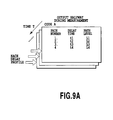
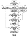
- Fig. 9B shows an example of the automatic re-synchronization check (S407) shown in Fig. 4.
- the delay profile is observed (S902) as an output given halfway in the measurement process.
- the path level weighted average delay time is calculated (S903) and it is determined whether it exceeds the width of the one-side re-synchronization window or not (S904). Further, it is also determined whether the sum of the path levels exceeds the automatic re-synchronization threshold or not (S905). If either answer is NO, the check time is initialized (S906) and it is determined that the automatic re-synchronization will not be conducted (S907). If both answers are YES, the check time is incremented (S908) and compared with the automatic re-synchronization protection time (S909).
- the automatic re-synchronization will be carried out (S910) if the check time is equal to or longer than the automatic re-synchronization protection time, in other words, if the pulse level weighted average delay time exceeds the width of the one-side re-synchronization window and the existent period of path where the sum of path levels exceeds the automatic re-synchronization threshold is equal to or longer than the automatic re-synchronization protection time.
- the width of the one-side re-synchronization window, the automatic re-synchronization threshold and the automatic re-synchronization protection time are parameters that can be set by the user as the automatic re-synchronization check conditions.
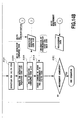
- Fig. 10 shows the method using a detection requested code list and a detection completed code list.
- the detection requested code list and the detection completed code list are used.
- Fig. 10 demonstrates how the three operations, namely, the synchronization point detection operation conducted in the synchronization unit 121, initial error detection check operation in the measurement unit 122 and re-synchronization check operation (manual, automatic, off-track) in the measurement unit 122, and the detection requested code list and detection completion code list are related with one another.
- the detection requested code list is initialized by the measurement code settings determined by the user.
- the measurement code settings describe the numbers of the codes that will be measured, names of the base stations as reference information and search numbers for list scanning.
- the detection requested code list is the code list of the codes that will be detected.
- the listed codes are referred to, from their top on the list, by the synchronization unit 121 for synchronization point detection.
- the code of which detection has been completed is removed from the detection requested code list and then transferred to the detection completion code list.
- the descriptions of the detection completed code list are the same as those of the detection requested code list except that the information about synchronization points is added in the completed code list.
- the measurement unit 122 conducts initial error detection on the codes described in the detection completed code list. If the initial error detection is determined as a failure, the corresponding code is removed from the detection completed code list and then transcribed on the detection requested code list so that the operation is returned to the synchronization unit 121. If the initial error detection is determined as successful, the storage operation begins in the measurement unit 122 and re-synchronization check operation starts. The code for which re-synchronization starts is removed from the detection completed code list for re-synchronization according to the setting, either of manual, automatic or on-track. Afterward, it is transferred to the detection requested code list and the operation is returned to the synchronization unit 121. If the mode of re-synchronization check is set at "automatic", the synchronization detection must be made with the current data measurement being continued. Thus the code is described on the detection requested code list, while it remains in the detection completed code list.
- Figs. 11A to 11D show examples of the measurement code settings, detection requested code list and detection completed code list.
- Fig. 11A shows the example of measurement code settings, where a user has specified eight codes with the code numbers 3, 6, 9, 55, 120, 378, 412, 501.
- Fig. 11B shows a detection requested code list that has been initialized according to the measurement code settings.
- Fig. 11C shows the state of a detection requested code list after the detentions of code 3 and code 6 have been completed.
- Fig. 11D shows a detection completed code list. The synchronization point is detected in the order of the search numbers described on the detection requested code list.
- Figs. 12A, 12B, 13A and 13B show examples of the synchronization point detection for the case where the re-synchronization mode is set at the automatic re-synchronization.
- the setting of re-synchronization mode is read out (S1201). If its mode is determined to be "automatic” , the processing flow branches to a flow of synchronization detection or the other flow of re-synchronization detection.
- Figs. 12A and 12B show examples of synchronization detection.
- the measurement code settings are read (S1202) and the detection requested code list is initialized (S1203).
- the codes on the detection requested code list are referred to (S1205) and the detection request is examined (S1206). If there is a detection request code on the list, the detection is started (S1207).
- the code number is removed from the detection requested code list (S1208), the code number and the synchronization point are saved (S1209) in the record of the same search number on the detection completed code list.
- the scanning of the detection requested code list based on the search number is constantly continued during measurement (S1211, S1212). Therefore, if the code number is described on the detection requested code list, its detection is conducted instantaneously.
- X%Y represents the remainder given when X is divided by Y, and && represents logical multiplication.
- Figs. 13A and 13B show examples of the re-synchronization detection operation.
- the initial error detection check condition (S1301), automatic re-synchronization check condition (S1302) and off-track check condition (S1303) are read, and then the detection completed code list is referred to (S1305).
- the detection completed code list is referred to (S1305).
- the automatic re-synchronization failure/success check (S1307), initial error detection check (S1308), off-track check (S1309) and automatic re-synchronization check (S1310) are carried out.
- the operation is returned to the detection process after the issue of a measurement cancellation order (S1311), data storage cancellation (S1312), removal from the detection completed code list (S1313), and transfer to the detection requested code list (S1314) .
- the same operations are executed if an off-track check is conducted.
- the code is listed on the detection requested code list (S1317) and the operation is returned to the detection process, while the current synchronization point (S1315) and data saving (S1316) are continued.
- the initial error detection check at the new synchronization point tells whether or not a new better synchronization point is found under the automatic re-synchronization. If the result of automatic re-synchronization check is YES, the detection completed code list is renewed to a new one for the new synchronization point (S1318), the synchronization point being thereby renewed (S1319). If all the checks have failed and the current synchronization point is determined as the best one, the current synchronization point is maintained (S1320) and data storage starts (S1321).
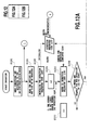
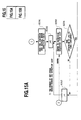
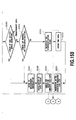
- Figs. 14A, 14B, 15A and 15B show examples of the synchronization point detection for the case where the re-synchronization mode is set at the manual re-synchronization.
- the setting of the re-synchronization mode is read (S1401). If its mode is determined to be set at "manual”, the operation branches to a flow of synchronization detection or the other flow of re-synchronization check.
- Figs. 14A and 14B show examples of the synchronization detection operation. Its flow is all the same as that for the case of the automatic re-synchronization (Fig. 12A and 12B).
- Figs. 15A and 15B show examples of the re-synchronization check.
- the initial error detection conditions are read (S1501) and then the detection completed code list is referred to according to the search number (S1503).
- the code of which code number and synchronization point are described on the detection completed code list is subject to the following check. If a code on the detection completed code list is determined to pass the initial error detection check (S1505) or a manual re-synchronization is ordered (S1506), the measurement (S1507) and data saving (S1508) are canceled. Then the code is removed from the detection completed code list (S1509) and moved to the detection requested code list (S1510) to make the process return to synchronization detection. Unless the code passes those checks, the current synchronization point is maintained (S1511) and data saving (S1512) is continued.
- Figs. 16A and 16B show the examples of an output given halfway in the measurement process according to the invention.
- Figs. 16A and 16B demonstrate an output given halfway in the measurement process obtained in parallel for each code as the result of the operations in Figs. 10 to 15A and 15B.
- the output is provided along with the information of time and location. This enhances the effectiveness of the data acquired as delay profile.
Applications Claiming Priority (2)
| Application Number | Priority Date | Filing Date | Title |
|---|---|---|---|
| JP2000105484 | 2000-04-06 | ||
| JP2000105484A JP3884896B2 (ja) | 2000-04-06 | 2000-04-06 | 通信品質取得装置および通信品質取得方法 |
Publications (3)
| Publication Number | Publication Date |
|---|---|
| EP1143633A2 true EP1143633A2 (de) | 2001-10-10 |
| EP1143633A3 EP1143633A3 (de) | 2003-02-19 |
| EP1143633B1 EP1143633B1 (de) | 2010-03-10 |
Family
ID=18618826
Family Applications (1)
| Application Number | Title | Priority Date | Filing Date |
|---|---|---|---|
| EP20010303249 Expired - Lifetime EP1143633B1 (de) | 2000-04-06 | 2001-04-05 | Vorrichtung und Verfahren zur Erfassung der Kommunikationsqualität |
Country Status (8)
| Country | Link |
|---|---|
| US (2) | US6968197B2 (de) |
| EP (1) | EP1143633B1 (de) |
| JP (1) | JP3884896B2 (de) |
| KR (1) | KR100454043B1 (de) |
| CN (1) | CN1217504C (de) |
| AU (1) | AU755059B2 (de) |
| DE (1) | DE60141494D1 (de) |
| SG (1) | SG105494A1 (de) |
Cited By (2)
| Publication number | Priority date | Publication date | Assignee | Title |
|---|---|---|---|---|
| WO2002001747A2 (en) * | 2000-06-27 | 2002-01-03 | Koninklijke Philips Electronics N.V. | Re-synchronization method for a communication device |
| EP2391162A1 (de) * | 2009-01-20 | 2011-11-30 | NTT DoCoMo, Inc. | Drahtlose basisstation und mobilstation |
Families Citing this family (9)
| Publication number | Priority date | Publication date | Assignee | Title |
|---|---|---|---|---|
| JP3884896B2 (ja) * | 2000-04-06 | 2007-02-21 | 株式会社エヌ・ティ・ティ・ドコモ | 通信品質取得装置および通信品質取得方法 |
| JP3423298B2 (ja) * | 2001-09-28 | 2003-07-07 | 三洋電機株式会社 | 携帯電話機、基地局探索方法及びプログラム |
| JP4771648B2 (ja) * | 2003-02-28 | 2011-09-14 | 京セラ株式会社 | 携帯電話機 |
| US7848741B2 (en) | 2003-12-30 | 2010-12-07 | Kivekaes Kalle | Method and system for interference detection |
| US7643811B2 (en) * | 2004-05-26 | 2010-01-05 | Nokia Corporation | Method and system for interference detection |
| JP2006180146A (ja) * | 2004-12-22 | 2006-07-06 | Nec Corp | Cdma受信装置及びそれに用いるパスサーチ方法 |
| KR101007013B1 (ko) * | 2008-12-31 | 2011-01-12 | 현담산업 주식회사 | 자동차용 연료펌프에 형성된 펌프부의 마찰저감구조 |
| CN102006140B (zh) * | 2009-09-03 | 2013-09-25 | 华为技术有限公司 | 数据传输的错误率检测及链路质量控制指示的方法、装置 |
| KR102595556B1 (ko) | 2021-07-12 | 2023-10-27 | 주식회사 엘지유플러스 | 지역별 통신 품질 상태를 판단하는 통신 시스템 및 그 제어방법 |
Citations (2)
| Publication number | Priority date | Publication date | Assignee | Title |
|---|---|---|---|---|
| WO1997040398A2 (en) * | 1996-04-25 | 1997-10-30 | Sirf Technology, Inc. | Spread spectrum receiver with multi-bit correlator |
| EP0989685A2 (de) * | 1998-09-24 | 2000-03-29 | Nec Corporation | CDMA Rake-Empfänger |
Family Cites Families (21)
| Publication number | Priority date | Publication date | Assignee | Title |
|---|---|---|---|---|
| US5084891A (en) * | 1989-09-08 | 1992-01-28 | Bell Communications Research, Inc. | Technique for jointly performing bit synchronization and error detection in a TDM/TDMA system |
| JP2605648B2 (ja) * | 1994-12-22 | 1997-04-30 | 日本電気株式会社 | Ss受信機における逆拡散符号位相検出装置 |
| JPH09307951A (ja) * | 1996-03-15 | 1997-11-28 | Matsushita Electric Ind Co Ltd | スペクトル拡散通信装置 |
| JP2747994B2 (ja) | 1996-03-18 | 1998-05-06 | 株式会社ワイ・アール・ピー移動通信基盤技術研究所 | 疑似ランダム信号同期回路 |
| US5696762A (en) * | 1996-03-25 | 1997-12-09 | Stanford Telecommunications, Inc. | Rapid-acquisition access channel scheme for CDMA systems |
| KR0164099B1 (ko) | 1996-03-26 | 1998-12-01 | 서정욱 | 부호 분할 다원 접속 시스템에서 동기화 대상 기지국 선정 방법 |
| JP3310160B2 (ja) | 1996-03-29 | 2002-07-29 | 松下電器産業株式会社 | スペクトラム拡散方式受信装置 |
| US5945948A (en) * | 1996-09-03 | 1999-08-31 | Motorola, Inc. | Method and apparatus for location finding in a communication system |
| JP3103311B2 (ja) | 1996-10-03 | 2000-10-30 | 国際電気株式会社 | Rake受信機 |
| JP3897427B2 (ja) * | 1997-12-01 | 2007-03-22 | 松下電器産業株式会社 | 基地局装置、移動局装置、移動体通信システム、無線送信方法及び無線受信方法 |
| JP3858433B2 (ja) * | 1998-03-30 | 2006-12-13 | ソニー株式会社 | パイロット信号検出方法及び受信機 |
| US6731622B1 (en) * | 1998-05-01 | 2004-05-04 | Telefonaktiebolaget Lm Ericsson (Publ) | Multipath propagation delay determining means using periodically inserted pilot symbols |
| JP3695732B2 (ja) | 1998-09-02 | 2005-09-14 | 富士通株式会社 | Cdma受信装置のサーチ装置 |
| JP3257522B2 (ja) * | 1998-10-06 | 2002-02-18 | 日本電気株式会社 | 移動通信端末機 |
| KR100340932B1 (ko) * | 1998-10-26 | 2002-06-20 | 조정남 | 비동기식 광대역 부호 분할 다중 접속 시스템에서의 셀 탐색 방법 |
| US6256338B1 (en) * | 1998-11-30 | 2001-07-03 | Motorola, Inc. | Method for determining fading correction factor in a communication system |
| JP3930187B2 (ja) * | 1999-03-03 | 2007-06-13 | 株式会社日立コミュニケーションテクノロジー | 同期制御方法、受信機、基地局及び移動端末 |
| US6650694B1 (en) * | 2000-02-18 | 2003-11-18 | Texas Instruments Incorporated | Correlator co-processor for CDMA RAKE receiver operations |
| JP3884896B2 (ja) * | 2000-04-06 | 2007-02-21 | 株式会社エヌ・ティ・ティ・ドコモ | 通信品質取得装置および通信品質取得方法 |
| JP3673700B2 (ja) * | 2000-06-27 | 2005-07-20 | 株式会社日立製作所 | スペクトル拡散信号を用いた測距及び位置測定方法、その方法を行う装置 |
| JP3547412B2 (ja) * | 2001-07-24 | 2004-07-28 | 株式会社日立製作所 | 無線端末装置及び測位システム |
-
2000
- 2000-04-06 JP JP2000105484A patent/JP3884896B2/ja not_active Expired - Fee Related
-
2001
- 2001-04-04 SG SG200102517A patent/SG105494A1/en unknown
- 2001-04-04 US US09/825,817 patent/US6968197B2/en not_active Expired - Lifetime
- 2001-04-05 EP EP20010303249 patent/EP1143633B1/de not_active Expired - Lifetime
- 2001-04-05 DE DE60141494T patent/DE60141494D1/de not_active Expired - Lifetime
- 2001-04-06 CN CN011207590A patent/CN1217504C/zh not_active Expired - Fee Related
- 2001-04-06 AU AU35062/01A patent/AU755059B2/en not_active Ceased
- 2001-04-06 KR KR10-2001-0018413A patent/KR100454043B1/ko active IP Right Grant
-
2004
- 2004-08-24 US US10/925,083 patent/US7545790B2/en not_active Expired - Fee Related
Patent Citations (2)
| Publication number | Priority date | Publication date | Assignee | Title |
|---|---|---|---|---|
| WO1997040398A2 (en) * | 1996-04-25 | 1997-10-30 | Sirf Technology, Inc. | Spread spectrum receiver with multi-bit correlator |
| EP0989685A2 (de) * | 1998-09-24 | 2000-03-29 | Nec Corporation | CDMA Rake-Empfänger |
Non-Patent Citations (1)
| Title |
|---|
| SADAYUKI ABETA ET AL: "A COHERENT DETECTION SYSTEM WITH A SUPPRESSED PILOT CHANNEL FOR DS/CDMA SYSTEMS" ELECTRONICS & COMMUNICATIONS IN JAPAN, PART I - COMMUNICATIONS, SCRIPTA TECHNICA. NEW YORK, US, vol. 79, PART 1, no. 4, 1 April 1996 (1996-04-01), pages 95-102, XP000587543 ISSN: 8756-6621 * |
Cited By (5)
| Publication number | Priority date | Publication date | Assignee | Title |
|---|---|---|---|---|
| WO2002001747A2 (en) * | 2000-06-27 | 2002-01-03 | Koninklijke Philips Electronics N.V. | Re-synchronization method for a communication device |
| WO2002001747A3 (en) * | 2000-06-27 | 2002-06-06 | Koninkl Philips Electronics Nv | Re-synchronization method for a communication device |
| US6603979B1 (en) | 2000-06-27 | 2003-08-05 | Koninklijke Philips Electronics N.V. | Re-synchronization method for a communication device |
| EP2391162A1 (de) * | 2009-01-20 | 2011-11-30 | NTT DoCoMo, Inc. | Drahtlose basisstation und mobilstation |
| EP2391162A4 (de) * | 2009-01-20 | 2014-11-05 | Ntt Docomo Inc | Drahtlose basisstation und mobilstation |
Also Published As
| Publication number | Publication date |
|---|---|
| AU755059B2 (en) | 2002-12-05 |
| KR100454043B1 (ko) | 2004-10-26 |
| CN1217504C (zh) | 2005-08-31 |
| CN1318923A (zh) | 2001-10-24 |
| JP2001292091A (ja) | 2001-10-19 |
| KR20010098472A (ko) | 2001-11-08 |
| AU3506201A (en) | 2001-10-11 |
| DE60141494D1 (de) | 2010-04-22 |
| US20050030916A1 (en) | 2005-02-10 |
| US20020022463A1 (en) | 2002-02-21 |
| SG105494A1 (en) | 2004-08-27 |
| US6968197B2 (en) | 2005-11-22 |
| JP3884896B2 (ja) | 2007-02-21 |
| EP1143633B1 (de) | 2010-03-10 |
| EP1143633A3 (de) | 2003-02-19 |
| US7545790B2 (en) | 2009-06-09 |
Similar Documents
| Publication | Publication Date | Title |
|---|---|---|
| EP0992122B1 (de) | Mobilstationssynchronisation in einem spreizspektrumnachrichtenübertragunssystem | |
| JP4260915B2 (ja) | Cdma受信機においてパイロット信号を捕捉する方法および装置 | |
| US6480558B1 (en) | Synchronization and cell search methods and apparatus for wireless communications | |
| JP4382479B2 (ja) | W−cdamハンドオフ検索のための方法および装置 | |
| EP1232571B1 (de) | Verfahren und vorrichtung zur bestimmung des standortes einer entfernten einheit unter benutzung von phasengesteuerten gruppenantennenelementen | |
| EP1121767B1 (de) | Ein cdma empfänger der nachführeinrichtungen zwischen mehreren rake-zweigen teilt | |
| AU755059B2 (en) | Apparatus and method for acquisition of communication quality | |
| US20070298739A1 (en) | Segmented cdma searching | |
| US20030117979A1 (en) | Cell search using peak quality factors | |
| EP1557016B1 (de) | Verfahren und anordnung zur kanalschätzung in einem funkkommunikationssystem | |
| AU2003259590A1 (en) | Cell search method and apparatus in a WCDMA system | |
| KR20040015348A (ko) | 사전규정된 코드 탐색 방법, 장치, 컴퓨터 판독가능한매체, 신호 및 시스템 | |
| EP1103126B1 (de) | Suchgerät für zellulare telefonie | |
| JP2001298405A (ja) | 目標セル信号を分離する方法 | |
| GB2364487A (en) | Pilot signal acquisition in a spread spectrum communication system such as a cdma cellular telephone system | |
| JP2001308780A (ja) | 目標セル信号を分離する方法及び装置 |
Legal Events
| Date | Code | Title | Description |
|---|---|---|---|
| PUAI | Public reference made under article 153(3) epc to a published international application that has entered the european phase |
Free format text: ORIGINAL CODE: 0009012 |
|
| AK | Designated contracting states |
Kind code of ref document: A2 Designated state(s): AT BE CH CY DE DK ES FI FR GB GR IE IT LI LU MC NL PT SE TR |
|
| AX | Request for extension of the european patent |
Free format text: AL;LT;LV;MK;RO;SI |
|
| PUAL | Search report despatched |
Free format text: ORIGINAL CODE: 0009013 |
|
| AK | Designated contracting states |
Designated state(s): AT BE CH CY DE DK ES FI FR GB GR IE IT LI LU MC NL PT SE TR |
|
| AX | Request for extension of the european patent |
Extension state: AL LT LV MK RO SI |
|
| 17P | Request for examination filed |
Effective date: 20030509 |
|
| AKX | Designation fees paid |
Designated state(s): DE FR GB IT |
|
| 17Q | First examination report despatched |
Effective date: 20050929 |
|
| GRAP | Despatch of communication of intention to grant a patent |
Free format text: ORIGINAL CODE: EPIDOSNIGR1 |
|
| GRAS | Grant fee paid |
Free format text: ORIGINAL CODE: EPIDOSNIGR3 |
|
| GRAA | (expected) grant |
Free format text: ORIGINAL CODE: 0009210 |
|
| AK | Designated contracting states |
Kind code of ref document: B1 Designated state(s): DE FR GB IT |
|
| REG | Reference to a national code |
Ref country code: GB Ref legal event code: FG4D |
|
| REF | Corresponds to: |
Ref document number: 60141494 Country of ref document: DE Date of ref document: 20100422 Kind code of ref document: P |
|
| PLBE | No opposition filed within time limit |
Free format text: ORIGINAL CODE: 0009261 |
|
| STAA | Information on the status of an ep patent application or granted ep patent |
Free format text: STATUS: NO OPPOSITION FILED WITHIN TIME LIMIT |
|
| 26N | No opposition filed |
Effective date: 20101213 |
|
| REG | Reference to a national code |
Ref country code: FR Ref legal event code: PLFP Year of fee payment: 16 |
|
| REG | Reference to a national code |
Ref country code: FR Ref legal event code: PLFP Year of fee payment: 17 |
|
| REG | Reference to a national code |
Ref country code: FR Ref legal event code: PLFP Year of fee payment: 18 |
|
| PGFP | Annual fee paid to national office [announced via postgrant information from national office to epo] |
Ref country code: GB Payment date: 20180329 Year of fee payment: 18 |
|
| PGFP | Annual fee paid to national office [announced via postgrant information from national office to epo] |
Ref country code: DE Payment date: 20180320 Year of fee payment: 18 |
|
| PGFP | Annual fee paid to national office [announced via postgrant information from national office to epo] |
Ref country code: IT Payment date: 20180420 Year of fee payment: 18 |
|
| PGFP | Annual fee paid to national office [announced via postgrant information from national office to epo] |
Ref country code: FR Payment date: 20190313 Year of fee payment: 19 |
|
| REG | Reference to a national code |
Ref country code: DE Ref legal event code: R119 Ref document number: 60141494 Country of ref document: DE |
|
| GBPC | Gb: european patent ceased through non-payment of renewal fee |
Effective date: 20190405 |
|
| PG25 | Lapsed in a contracting state [announced via postgrant information from national office to epo] |
Ref country code: DE Free format text: LAPSE BECAUSE OF NON-PAYMENT OF DUE FEES Effective date: 20191101 Ref country code: GB Free format text: LAPSE BECAUSE OF NON-PAYMENT OF DUE FEES Effective date: 20190405 |
|
| PG25 | Lapsed in a contracting state [announced via postgrant information from national office to epo] |
Ref country code: IT Free format text: LAPSE BECAUSE OF NON-PAYMENT OF DUE FEES Effective date: 20190405 |
|
| PG25 | Lapsed in a contracting state [announced via postgrant information from national office to epo] |
Ref country code: FR Free format text: LAPSE BECAUSE OF NON-PAYMENT OF DUE FEES Effective date: 20200430 |