EP0988943B1 - Drehbare Messerwalze - Google Patents
Drehbare Messerwalze Download PDFInfo
- Publication number
- EP0988943B1 EP0988943B1 EP99114572A EP99114572A EP0988943B1 EP 0988943 B1 EP0988943 B1 EP 0988943B1 EP 99114572 A EP99114572 A EP 99114572A EP 99114572 A EP99114572 A EP 99114572A EP 0988943 B1 EP0988943 B1 EP 0988943B1
- Authority
- EP
- European Patent Office
- Prior art keywords
- suction
- duct
- bore
- knife
- fresh
- Prior art date
- Legal status (The legal status is an assumption and is not a legal conclusion. Google has not performed a legal analysis and makes no representation as to the accuracy of the status listed.)
- Expired - Lifetime
Links
Images


Classifications
-
- B—PERFORMING OPERATIONS; TRANSPORTING
- B26—HAND CUTTING TOOLS; CUTTING; SEVERING
- B26D—CUTTING; DETAILS COMMON TO MACHINES FOR PERFORATING, PUNCHING, CUTTING-OUT, STAMPING-OUT OR SEVERING
- B26D7/00—Details of apparatus for cutting, cutting-out, stamping-out, punching, perforating, or severing by means other than cutting
- B26D7/18—Means for removing cut-out material or waste
- B26D7/1845—Means for removing cut-out material or waste by non mechanical means
- B26D7/1863—Means for removing cut-out material or waste by non mechanical means by suction
-
- B—PERFORMING OPERATIONS; TRANSPORTING
- B26—HAND CUTTING TOOLS; CUTTING; SEVERING
- B26F—PERFORATING; PUNCHING; CUTTING-OUT; STAMPING-OUT; SEVERING BY MEANS OTHER THAN CUTTING
- B26F1/00—Perforating; Punching; Cutting-out; Stamping-out; Apparatus therefor
- B26F1/38—Cutting-out; Stamping-out
- B26F1/384—Cutting-out; Stamping-out using rotating drums
-
- Y—GENERAL TAGGING OF NEW TECHNOLOGICAL DEVELOPMENTS; GENERAL TAGGING OF CROSS-SECTIONAL TECHNOLOGIES SPANNING OVER SEVERAL SECTIONS OF THE IPC; TECHNICAL SUBJECTS COVERED BY FORMER USPC CROSS-REFERENCE ART COLLECTIONS [XRACs] AND DIGESTS
- Y10—TECHNICAL SUBJECTS COVERED BY FORMER USPC
- Y10S—TECHNICAL SUBJECTS COVERED BY FORMER USPC CROSS-REFERENCE ART COLLECTIONS [XRACs] AND DIGESTS
- Y10S83/00—Cutting
- Y10S83/911—Envelope blank forming
-
- Y—GENERAL TAGGING OF NEW TECHNOLOGICAL DEVELOPMENTS; GENERAL TAGGING OF CROSS-SECTIONAL TECHNOLOGIES SPANNING OVER SEVERAL SECTIONS OF THE IPC; TECHNICAL SUBJECTS COVERED BY FORMER USPC CROSS-REFERENCE ART COLLECTIONS [XRACs] AND DIGESTS
- Y10—TECHNICAL SUBJECTS COVERED BY FORMER USPC
- Y10T—TECHNICAL SUBJECTS COVERED BY FORMER US CLASSIFICATION
- Y10T83/00—Cutting
- Y10T83/202—With product handling means
- Y10T83/2066—By fluid current
- Y10T83/207—By suction means
Definitions
- the invention relates to a rotatable knife roller according to the preamble of claim 1.
- a knife roll is known from US-A-4 537 588. It is used to cut out the window envelope window. While the envelope blank is transported with the blade roll the resulting through the pane waste piece must be held for a certain time to be discharged and then to a waste hopper. The purpose of this is the axially aligned single row of suction openings, which open within the area enclosed by the foil knives in the roll surface.
- a provided with the Saugloch #2n bowl-shaped ring sector is mounted on the support shaft and can be rotated relative to the carrier shaft and fix that are of the rows of holes optionally two adjacent rows of holes with the Verteilernuten and thus with the Saugluft horrkanälen in combination.
- these two suction hole rows which can be acted upon with vacuum serve exclusively to hold the leading blank edge against the counter-roller.
- the adjustment only allows adaptation to different formats or distances between the leading edge of the blank and the window to be cut out. This cutting is done not in the range of Saugloch #2n but in a subsequent downstream cutting sector with a particularly hard surface and without suction holes. The cut waste pieces can therefore not be targeted and transported by vacuum action to a predetermined discharge point.
- EP 0 436 142 discloses a knife roller in which foil knives can be clamped on a roll body part. At its periphery, it has a plurality of suction holes arranged in rows for temporarily holding pieces of material cut out of a letter envelope blank.
- suction-air control disks arranged on the front side of the roller body part, it is possible to supply selectively controlled suction-air rows, which are supplied by longitudinal bores of the roller axle, to specific suction-hole rows. In this way is achieved in the circumferential direction of the knife roller offset cut pieces of material to take time accurately and deliver.
- the invention has for its object to provide a knife roller for the Envelope making and other applications to be designed so that they as versatile as possible and, above all, capable of more than just To safely and reliably dispose of one piece of waste per blank to be processed. It should also allow a window opening close to the leading Transport edge of a letter envelope blank to bring.
- Fig. 1 comprises a Cutting station 1 for window envelopes a knife roller 2 and a as Counter tool serving stationary cutting bar 3, between which a series of Letter envelope blanks 4 is passed and processed.
- the cutting bar 3 is clamped with a bar 6 stored in a carrier 5 and together with this on the knife roller 2 back and away from it.
- the cutting station 1a according to FIG. 2 has a rotating counter-roller 3a as Counter tool to the knife roller 2, between which the result of Letter envelope blanks 4 is passed and processed.
- the counter roll 3a is stored in a carrier, not shown, and with this on the knife roller. 2 towards and away from this movable.
- the letter envelope blank 4 coming from a straight transport path 7 is gripped by the knife roller 2 and guided along a circular path under the counter tool, cutting bar 3 or counter roller 3a, whereby a window opening 8 'is cut out.
- the knife roller 2 (FIG. 3) has at its beginning 9 a multiplicity of suction openings 11 arranged in rows 10.
- the letter envelope blank 4 is held on the knife roller 2 via a suction and transport angle range ⁇ by means of suction air, while maintaining its predetermined phase position and is then transferred in precise position to a laxative roller 12.
- the piece of material 8 is held by means of suction air in the window knife periphery and finally delivered after a suction and transport angle range ⁇ in a suction funnel 13, optionally blown off with the aid of compressed air.
- the cutting and holding the cut out of the window 8 'piece of material 8 and its delivery into the suction funnel 13 carried out at the cutting station 1 shown in FIG. 1 in the same manner as in cutting station 1a according to FIG. Fig. 3 shows the knife roller 2 or its storage and essential parts of the knife roller 2 in section, but without a foil knife and without serving for attaching and tensioning the foil knife parts.
- the knife roller 2 comprises a support shaft 14, which is supported by means of a plurality of ball bearings 15 in machine frames 16,18 and driven by a gear 17.
- a cylindrical roller body part 19 is fastened on the carrier shaft 14, on the circumference 20 of which the suction openings 11 in the form of rows 10 are arranged.
- suction channels 21, which are in air-conducting connection with suction openings 11, are disposed at a distance d from the axis of rotation 2 'of the knife roller 2.
- three rows 10 of suction openings 11 are assigned to a suction channel 21, except in the area of a knife attachment 22, where in each case only two rows 10 are associated with a suction channel 21.
- the knife attachment 22 with which in a direction of rotation 23 of the knife roller leading ends 26 are defined by foil blades 24, includes a axially parallel recess 25 in the roll body part 19, in which the ends 26 at an angle bent with the help of a terminal block 27 are fixed.
- the foil knife 24 is held in a known manner, e.g. by means arranged in the roller body part 19 magnetic elements or by Determining the trailing in the direction of rotation 23 end with a Clamping device similar to the knife attachment 22. Both types of attachment belong to the state of the art and are not described here.
- a foil knife 24 In use as a so-called window knife, a foil knife 24 has one of Shape of a window opening 8 'corresponding closed cutting edge 28. In the surface of the foil cutter 24 enclosed by the cutting edge 28 for sucking the cut piece of material 8 near one in the direction of rotation 23 leading cutting edge 28 'openings 29 provided in the Inlet openings 11 open.
- apertures 30 of the film knife 24 are shown in FIG Direction of rotation 23 are arranged in front of the cutting edge 28 'and in the likewise Inlet openings 11 open. These openings 30 are for detecting the leading end 4 'provided a letter envelope blank 4, wherein a Window opening 8 'near the leading end 4' is cut out.
- Fig. 7 the normal case is shown, with the leading end 4 of a Letter envelope blanks 4 by means arranged in rows 10 suction openings 11 directly is held on the circumference 20 of the roller body part 19.
- a suction air control valve 31 On the front side on the roller body part 19, a suction air control valve 31 is arranged, the is mounted on the frame wall 18 by means of a spacer and centering bushing 32.
- roll body part 19 is the Saugluft horrventil 31 rotatably disposed, but in or against the Direction of rotation 23 adjustable. Moreover, it is not as a closed rotary body, but for better accessibility and ease of maintenance horseshoe-shaped.
- the Saugluft horrventil 31 has a Saugluft horrkanal 33, from which, as shown in Fig. 3 and Fig. 1, the Suction channels 21 via a suction and transport angle range ⁇ or ⁇ with Suction can be acted upon.
- the Saug povertymaschinekanal 33 is stepped and has a first Channel zone 34 for the intake and transport angle range ⁇ on and a second Channel zone 35 for the intake and transport angle range ⁇ .
- the suction air supply 36 connects the Saug poverty horrinal 33 via feeders not shown with a Vacuum source.
- the channel zones 34 and 35 are each a fresh air duct 36 and 37, respectively downstream from where a reduction of the negative pressure in the suction channels 21st and suction openings 11 is caused.
- the fresh air duct 37 (Fig.
- a slightly modified variant 31 'of the control head 31 is shown.
- the stepped Saug povertymaschinekanales 33 with the channel zones 34,35 two separate, concentric Saugluft horrkanäle 39,40 provided, which in turn, the fresh air ducts 36 and 37 are arranged downstream.
- each suction channel 21 is a 3/3-way valve 41 associated with the aid of either an air-conducting connection between the suction channel 21 and a frontally disposed inner or outer through hole 42 and 43 produced is.
- the through-bores 42, 43 which are arranged radially offset at a distance d 1 or d 2 from the axis of rotation 2 ', pass through the channel zone 34 and fresh-air channel 36 or the channel zone 35 and fresh-air channel 37 at each cylinder revolution (FIG while cyclically charged with suction or fresh air. Since in the exemplary embodiment d and d 1 are the same, in each case a suction channel 21 and a through hole 42 assigned to it are axially aligned.
- a 3/3-way valve 41 is formed from a radial blind hole 44, into which the suction channel 21 opens from the side of the roll body and from the side of the suction air control valve 31, 31 'the through holes 42.43.
- a rotatable control sleeve 45 is arranged and secured by means not shown sealing and holding elements.
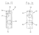
- the control bush 45 has the shape of a hollow cylinder, with an interior space 46 which is closed towards the periphery 20.
- the interior 46 corresponding to the distance d 2 opens a bore 47 and this opposite to the distance d, d 1 a bore 48. 90 ° to the bore 48 are corresponding to the distance d, d 1 two opposing holes 49,50 in the control sleeve 45th arranged.
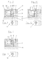
- control sleeve 45 is in different Function positions 51,52,53 shown.
- Fig. 7 the open position 51 is shown, in which an air-conducting connection from the through hole 43 via bore 47, interior 46, bore 48 and Suction channel 21 to suction holes 11 of a corresponding row 10 is made.
- Suction channel 21 to suction holes 11 of a corresponding row 10 is made.
- Fig. 9 shows the control sleeve 45 in the open position 52, in which an air-conducting connection between the channel zone 34 via through hole 42, bore 49, interior 46, bore 50 and suction channel 21 is made to selected suction ports 11.
- Fig. 11 shows the control sleeve 45 in the closed position 53, in which the respective suction channel 21 is shut off.
- the functional positions 51,52,53 are freely selectable.
- the functional positions of the control bushes 45 are clear from the positional alignment of marking grooves 54, 55 mounted on them in relation to circumferential marking grooves 56, 57 arranged on the circumference 20 of the roller body part 19.
- the knife roller 2 is adjusted in its phase position relative to the envelope machine so that a window opening to be introduced 8'an desired location on the machine cycle delivered in a regular phase envelope envelope blank 4.
- one or more 3/3-way valves 41 are brought into the open position 52 by appropriate selection and adjustment.
- selected rows 10 of suction openings 11 are acted upon by suction air from the channel zone 34 or suction air channel 39, for transporting the envelope envelope 4 over the intake and transport angle range ⁇ .
- FIG Invention regardless of the format of a letter envelope blank 4 and the number, Size and location of it to be introduced window openings 8 'always the Possibility through targeted activation of selected or required series 10 of suction holes 11 a smooth, proper transport of Letter envelope blanks 4 and the cut pieces of material 8 too guarantee.
- window openings 8 ' close to the transport direction in the 23rd leading edge 4 'of a letter envelope blank 4 to place.
Landscapes
- Life Sciences & Earth Sciences (AREA)
- Forests & Forestry (AREA)
- Engineering & Computer Science (AREA)
- Mechanical Engineering (AREA)
- Making Paper Articles (AREA)
- Details Of Cutting Devices (AREA)
- Perforating, Stamping-Out Or Severing By Means Other Than Cutting (AREA)
- Advancing Webs (AREA)
- Photosensitive Polymer And Photoresist Processing (AREA)
- Spinning Or Twisting Of Yarns (AREA)
- Massaging Devices (AREA)
- Delivering By Means Of Belts And Rollers (AREA)
Description
Eine derartige Messerwalze ist aus der US-A-4 537 588 bekannt. Sie dient zum Ausschneiden des Fensters von Fensterbriefumschlägen. Während der Briefhüllenrohling mit der Messerwalze transportiert wird muß das durch den Fensterausschnitt entstandene Abfallstück noch eine gewisse Zeit festgehalten werden, um dann an einen Abfalltrichter abgegeben zu werden. Dazu dient die axial ausgerichtete einzige Reihe von Saugöffnungen, die innerhalb des von den Folienmessern umschlossenen Bereichs in der Walzenoberfläche münden. Es ist zwar eine weitere axial verlaufende Reihe von Saugöffnungen in der Walzenoberfläche vorgesehen, die an einen eigenen Saugluftsteuerkanal in der Trägerwelle angeschlossen ist, diese Sauglochreihe befindet sich jedoch in Drehrichtung der Messerwalze vor den Messern und dient dazu, zeitweise die Vorderkante des Briefhüllenrohlings auf der Walzenoberfläche festzuhalten.
Mit dieser Messerwalze läßt sich nur ein einziges Fenster ausschneiden und das ausgeschnittene Materialstück bzw. Abfallstück von der Messerwalze zu einer in Umfangsrichtung nachfolgenden Abgabestelle mitnehmen. Außerdem kann nur ein bestimmtes Rohlingsformat bearbeitet werden, bei dem der Abstand des Fensters zur Vorderkante des Rohlings innerhalb eines vergleichsweise engen Bereichs liegt.
Ferner ist es aus der US-A-3 172 321 bekannt, zum Ausschneiden von Fenstern eine mit einer Messerwalze zusammenwirkende Gegenwalze vorzusehen, die mit einem Fenster zu versehende Briefhüllenrohlinge an der Messerwalze vorbei transportiert und dazu in ihrer Oberfläche mehrere im Umfangsabstand hintereinander angeordnete und axial verlaufende Reihen von Saugöffnungen aufweist, die wahlweise und gesteuert mit Vakuum beaufschlagbar sind. Dazu sind in einer Trägerwelle zwei axiale Saugluftsteuerkanäle vorgesehen, die über im wesentlichen radiale Kanäle mit je einem axialen Verteilerkanal in der Umfangsfläche der Trägerwelle in Verbindung stehen. Ein mit den Sauglochreihen versehener schalenförmiger Ringsektor ist auf der Trägerwelle gelagert und läßt sich so gegenüber der Trägerwelle verdrehen und fixieren, daß von den Lochreihen wahlweise jeweils zwei benachbarte Lochreihen mit den Verteilernuten und damit mit den Saugluftsteuerkanälen in Verbindung stehen. Diese beiden mit Vakuum beaufschlagbaren Sauglochreihen dienen jedoch ausschließlich dazu, die vorlaufende Rohlingskante an der Gegenwalze festzuhalten. Die Verstellung ermöglicht lediglich eine Anpassung an unterschiedliche Formate bzw. Abstände zwischen vorlaufender Rohlingskante und dem auszuschneidenden Fenster. Dieses Ausschneiden erfolgt nicht im Bereich der Sauglochreihen sondern in einem in Umlaufrichtung nachfolgenden Schneidsektor mit besonders harter Oberfläche und ohne Sauglöcher. Die ausgeschnittenen Abfallstücke lassen sich also nicht gezielt und mittels Vakuumeinwirkung an eine vorbestimmte Abwurfstelle transportieren. Darüberhinaus ist aus der EP 0 436 142 eine Messerwalze bekannt, bei der auf einem Walzenkörperteil Folienmesser aufspannbar sind. An ihrem Umfang weist sie eine Vielzahl von in Reihen angeordneten Sauglöchern auf, zum vorübergehenden Festhalten von aus einem Briefhüllenrohling ausgeschnittenen Materialstücken. Mittels stirnseitig am Walzenkörperteil angeordneten Saugluftsteuerscheiben ist es möglich, periodisch angelieferte, gesteuerte Saugluft, die durch Längsbohrungen der Walzenachse zugeführt wird, gezielt bestimmten Sauglochreihen zuzuführen. Hierdurch wird erreicht, in Umfangsrichtung der Messerwalze versetzt ausgeschnittene Materialstücke zeitlich genau zu ergreifen und abzugeben. Die mit der Messerwalze synchron umlaufenden Saugluftsteuerscheiben sind lediglich relativ zum Walzenkörperteil verstellbar und erfüllen nur eine Verteilerfunktion, um ausgewählte Sauglochreihen mit Saugluft zu beaufschlagen.
Nachteilig hierbei ist der lange Weg der gesteuerten Saugluft von einem Saugluftsteuerventil durch die Längsbohrungen und die Saugluftsteuerscheiben hindurch zu ihrem Einsatzort an den Sauglöchern am Umfang der Messerwalze. Dadurch sind bei hohen Drehzahlen der Messerwalze ein zeitlich exaktes Ergreifen und Abgeben von ausgeschnittenen Materialstücken stark beeinträchtigt. Da bei dieser Messerwalze, in einer technisch sinnvollen Ausführung, nur maximal zwei Saugluftsteuerscheiben einsetzbar sind, ist die Anzahl der bei einer Einstellung gezielt mit Saugluft beaufschlagbarer Sauglochreihen auf zwei begrenzt und so auch die Anzahl der bei einer Walzenumdrehung transportierbarer Materialstücke. Zudem wird zum Transport von Briefhüllenrohlingen eine zusätzliche Saugleiste benötigt, die eine eigene Lagerung, Saugluftversorgung und einen eigenen Antrieb benötigt. Durch die räumlich eingeschränkte Anordnung von Saugleiste und Schneidfolie ist es nicht möglich, Fensterausschnitte nahe an dem von der Saugleiste erfaßten Ende des Briefhüllenrohlings zu plazieren.
Zunächst wird die Messerwalze im Phasenwinkel relativ zur Briefumschlagmaschine so eingestellt, daß Fensterausschnitte an gewünschter Stelle im Briefhüllenrohling vorgenommen werden, der im Maschinenzyklus durch die Schneidstation transportiert wird. Sodann wird durch entsprechende Auswahl und Einstellung eines 3/3-Wegeventiles eine Sauglochreihe im Bereich der vorlaufenden Kante des Briefhüllenrohlings als Transportsaugreihe zum Transport des Rohlings für einen Ansaug- und Transportwinkelbereich α aktiviert. In ähnlicher Weise werden die Sauglochreihen für den Transport von ausgeschnittenen Materialstücken über den Ansaug- und Transportwinkelbereich β aktiviert.
Weitere Merkmale der Erfindung gehen aus den Unteransprüchen in Zusammenhang mit der Beschreibung und Zeichnung hervor.
Die mit der Erfindung erzielten Vorteile sind insbesondere darin zu sehen, daß unabhängig von der Größe sowie Anzahl und Lage von Fensterausschnitten in einem Briefhüllenrohling durch die entsprechende Auswahl und Einstellung von 3/3-Wegeventilen die richtigen Sauglochreihen für den Transport des Briefhüllenrohlings bzw. der Materialausschnitte über den Ansaug- und Transportbereich α bzw. β aktivierbar sind.
Durch die Merkmale von Anspruch 3 ist darüberhinaus möglich, Fensterausschnitte nahe an der vorlaufenden Kante eines Briefhüllenrohlings auszuschneiden und durch Aktivierung der richtigen Sauglochreihen sowohl die Materialausschnitte als auch die vorlaufende Kante des Briefhüllenrohlings selbst durch die Durchbrüche im Folienmesser hindurch zu erfassen.
Die Erfindung wird nachstehend anhand von Ausführungsbeispielen, die in der Zeichnung dargestellt sind, näher beschrieben. Dabei zeigen
- Fig. 1
- eine Prinzipskizze einer Schneidstation mit einer Messerwalze
- Fig. 2
- eine Prinzipskizze einer Schneidstation mit einer Messerwalze und einer abgewandelten Saugluftsteuerung
- Fig. 3
- im Schnitt wesentliche Teile der Messerwalze und ihre Lagerung
- Fig. 4
- Teilschnitt des Walzenkörperteils der Messerwalze mit aufgespanntem Folienmesser
- Fig. 5
- eine Abwicklung des Walzenkörperteils mit einem Folienmesser und einem Briefhüllenrohling
- Fig. 6
- eine Abwicklung des Walzenkörperteils mit einem abgewandelten Folienmesser mit einem Briefhüllenrohling
- Fig. 7
- Schnittansicht eines 3/3-Wegeventils in Offenstellung für den Ansaug- und Transportwinkelbereich β von Materialausschnitten
- Fig. 8
- Draufsicht des 3/3-Wegeventils in Pfeilrichtung VIII
- Fig. 9
- Schnittansicht eines 3/3-Wegeventils in Offenstellung für den Ansaug- und Transportwinkelbereich α von Briefhüllenrohlingen
- Fig. 10
- Draufsicht des 3/3-Wegeventils in Pfeilrichtung X
- Fig.11
- Schnittansicht eines 3/3-Wegeventiles in Schließstellung
- Fig. 12
- Draufsicht des 3/3-Wegeventils in Pfeilrichtung XII
- Fig. 13
- Schnittansicht einer Steuerbuchse
- Fig. 14
- Seitenansicht der Steuerbuchse.
Das Ausschneiden und Festhalten des aus dem Fenster 8' ausgeschnittenen Materialstückes 8 und dessen Abgabe in den Absaugtrichter 13 erfolgen bei der Schneidstation 1 gemäß Fig. 1 in gleicher Weise wie bei Schneidstation 1a gemäß Fig.2.
Die Fig. 3 zeigt die Messerwalze 2 bzw. ihre Lagerung sowie wesentliche Teile der Messerwalze 2 im Schnitt, jedoch ohne Folienmesser und ohne die zum Befestigen und Spannen der Folienmesser dienenden Teile. Die Messerwalze 2 umfaßt eine Trägerwelle 14, die mit Hilfe von mehreren Kugellagern 15 in Maschinengestellen 16,18 gelagert und mittels eines Zahnrades 17 antreibbar ist. Zwischen den Maschinengestellen 16,18 ist ein zylindriges Walzenkörperteil 19 auf der Trägerwelle 14 befestigt, an dessen Umfang 20 die Saugöffnungen 11 in Form von Reihen 10 angeordnet sind. Im Walzenkörperteil 19 sind, wie in Fig. 3 und Fig. 4 gezeigt, im Abstand d von der Rotationsachse 2'der Messerwalze 2 Saugkanäle 21 achsparallel angeordnet, die mit Saugöffnungen 11 in luftleitender Verbindung stehen. Im Ausführungsbeispiel sind jeweils drei Reihen 10 von Saugöffnungen 11 einem Saugkanal 21 zugeordnet, außer im Bereich einer Messerbefestigung 22, wo jeweils nur zwei Reihen 10 einem Saugkanal 21 zugehörig sind.
Fig. 11 zeigt die Steuerbuchse 45 in Schließstellung 53, in der der jeweilige Saugkanal 21 abgesperrt ist. Für jedes 3/3-Wegeventil 41 und damit auch für die zugeordneten Saugkanäle 21 und Reihen 10 von Saugöffnungen 11 sind die Funktionsstellungen 51,52,53 frei wählbar. Die Funktionsstellungen der Steuerbuchsen 45 werden durch die lagemäßige Ausrichtung von an diesen angebrachten Markierungsnuten 54,55 in Relation zu am Umfang 20 des Walzenkörperteils 19 angeordneten, umlaufenden Markierungsrillen 56,57 deutlich.
Zunächst wird, durch nicht gezeigte Verstellelemente im Antrieb, die Messerwalze 2 in ihrer Phasenlage relativ zur Briefumschlagmaschine so eingestellt, daß eine einzubringende Fensteröffnung 8'an gewünschter Stelle am im Maschinentakt in regelmäßiger Phasenlage angelieferten Briefhüllenrohling 4 vorgenommen wird. Sodann werden durch entsprechende Auswahl und Einstellung ein oder mehrere 3/3-Wegeventile 41 in Offenstellung 52 gebracht. Hierdurch werden ausgesuchte Reihen 10 von Saugöffnungen 11 von der Kanalzone 34 bzw. Saugluftkanal 39 aus mit Saugluft beaufschlagt, zum Transport des Briefhüllenrohlings 4 über den Ansaug- und Transportwinkelbereich α.
Claims (8)
- Drehbare Messerwalze mit mindestens einem Folienmesser, das an einem Walzenkörperteil befestigbar ist und das zum Ausschneiden von Fensteröffnungen eine scharfe, endlose, in sich geschlossene Schneidkante trägt, innerhalb der Durchbrüche für Saugöffnungen angeordnet sind, mit mindestens einem stirnseitig am Walzenkörperteil und relativ drehbar zu diesem angeordneten Saugluftsteuerventil, das mindestens einen Saugluftsteuerkanal und mindestens einen Frischluftkanal aufweist und mit Saugöffnungen zum vorübergehenden Festhalten eines Briefhüllenrohlings über einen Ansaug- und Transportwinkelbereich α und eines vom Folienmesser ausgeschnittenen Materialstückes über einen Ansaug- und Transportwinkelbereich β, wobei die Saugöffnungen in Reihen angeordnet sind, denen im Walzenkörperteil Saugkanäle zugeordnet sind und wobei die Saugöffnungen durch die Saugkanäle hindurch mit dem Saugluftsteuerkanal und dem Frischluftkanal luftleitend verbindbar sind, dadurch gekennzeichnet, daß vor dem Saugluftsteuerventil (31,31') dem Saugkanal (21) ein 3/3-Wegeventil (41) zugeordnet ist, mit je einer Offenstellung (52,51) für den Ansaug- und Transportwinkelbereich α, β und einer gemeinsamen Schließstellung (53) für die Ansaug- und Transportwinkelbereiche α und β.
- Messerwalze nach Anspruch 1, dadurch gekennzeichnet, daß das Saugluftsteuerventil (31) einen gestuft ausgebildeten Saugluftsteuerkanal (33) aufweist, mit einer ersten Kanalzone (34) für den Ansaug- und Transportwinkelbereich α, der ein erster Frischluftkanal (36) nachgeordnet ist und einer zweiten Kanalzone (35) für den Ansaug- und Transportwinkelbereich β, der ein zweiter Frischluftkanal (37) nachgeordnet ist, und daß die erste Kanalzone (34) und der erste Frischluftkanal (36) einer Durchgangsbohrung 42 im Walzenkörperteil (19) und die zweite Kanalzone (35) und der zweite Frischluftkanal (37) einer Durchgangsbohrung (43) im Walzenkörperteil (19) zugeordnet sind.
- Messerwalze nach Anspruch 1, dadurch gekennzeichnet, daß das Saugluftsteuerventil (31') zwei radial versetzte, konzentrisch angeordnete Saugluftsteuerkanäle (39,40) aufweist, denen jeweils ein Frischluftkanal (36,37) nachgeordnet ist, und daß der Saugluftsteuerkanal (39) und der Frischluftkanal (36) der Durchgangsbohrung (42) und der Saugluftsteuerkanal (40) und der Frischluftkanal (37) der Durchgangsbohrung (43) zugeordnet sind.
- Messerwalze nach einem der Ansprüche 1-3, dadurch gekennzeichnet, daß die 3/3-Wegeventile (41) in das Walzenkörperteil (19) integriert sind, und ein 3/3-Wegeventil (41) gebildet wird aus einer radial im Walzenkörperteil (19) angeordneten Bohrung (44), wobei von einer Seite ein Saugkanal (21) und von der anderen Seite radial versetzt eine innere und eine äußere Durchgangsbohrung (42,43), die zum Saugluftsteuerventil (31) hin offen sind, in die Bohrung (44) einmünden, und wobei in der Bohrung (44) eine drehbare Steuerbuchse (45) angeordnet ist, die einen Innenraum (46) aufweist und die zum Zylinderumfang (20) hin geschlossen ist und die Bohrungen (47,48,49,50) derart angeordnet aufweist, daß sie in der Offenstellung (51) die Durchgangsbohrung (43) via den Bohrungen (47,48) und dem Innenraum (46) sowie in der Offenstellung (52) die Durchgangsbohrung (42) via den Bohrungen (49,50) und dem Innenraum (46) mit dem Saugkanal (21) luftleitend verbindbar sind, und daß in einer Schließstellung (53) der Saugkanal (21) zu den Durchgangsbohrungen (42,43) hin verschließbar ist.
- Messerwalze nach einem der Ansprüche 1-4, dadurch gekennzeichnet, daß je nach Format eines Briefhüllenrohlings (4) und der Anzahl, Größe und Lage der Fensterausschnitte darin gezielt luftleitende Verbindungen zwischen Saugöffnungen (11) ausgewählter Reihen (10) und dem Saugluftsteuerventil (31,31') herstellbar sind, durch Offenstellung (51,52) bei gezielt ausgewählten 3/3-Wegeventilen (41).
- Messerwalze nach Anspruch 2, dadurch gekennzeichnet, daß in einer Drehrichtung (23) der Messerwalze (2) vor einer ersten Schneidkante 28' zusätzliche Durchbrüche (30) im Folienmesser (24) angeordnet sind, zum Ergreifen der vorlaufenden Kante (4') eines Briefhüllenrohlings (4), bei dem ein Fensterausschnitt nahe an der vorlaufenden Kante (4') plaziert ist.
- Messerwalze nach Anspruch 2 oder 3, dadurch gekennzeichnet, daß mindestens ein Frischluftkanal (36,37) mit Druckluft beaufschlagbar ist.
- Messerwalze nach Anspruch 1, dadurch gekennzeichnet, daß an beiden Stirnseiten des Walzenkörperteils (19) je ein Saugluftsteuerventil (31,31') angeordnet ist.
Applications Claiming Priority (2)
| Application Number | Priority Date | Filing Date | Title |
|---|---|---|---|
| DE19841834A DE19841834A1 (de) | 1998-09-12 | 1998-09-12 | Drehbare Messerwalze |
| DE19841834 | 1998-09-12 |
Publications (3)
| Publication Number | Publication Date |
|---|---|
| EP0988943A2 EP0988943A2 (de) | 2000-03-29 |
| EP0988943A3 EP0988943A3 (de) | 2002-12-18 |
| EP0988943B1 true EP0988943B1 (de) | 2004-12-01 |
Family
ID=7880778
Family Applications (1)
| Application Number | Title | Priority Date | Filing Date |
|---|---|---|---|
| EP99114572A Expired - Lifetime EP0988943B1 (de) | 1998-09-12 | 1999-07-24 | Drehbare Messerwalze |
Country Status (7)
| Country | Link |
|---|---|
| US (1) | US6205899B1 (de) |
| EP (1) | EP0988943B1 (de) |
| JP (1) | JP4439627B2 (de) |
| AT (1) | ATE283751T1 (de) |
| CA (1) | CA2282069A1 (de) |
| DE (2) | DE19841834A1 (de) |
| ES (1) | ES2234187T3 (de) |
Families Citing this family (27)
| Publication number | Priority date | Publication date | Assignee | Title |
|---|---|---|---|---|
| DE19925612B4 (de) | 1999-06-04 | 2007-10-31 | WINKLER + DüNNEBIER AG | Drehbare Messerwalze mit Folienmesser |
| DE10115595A1 (de) * | 2001-03-29 | 2002-10-02 | Winkler & Duennebier Ag | Messerwalze |
| US6715394B2 (en) * | 2002-05-07 | 2004-04-06 | W+D Machinery Co., Inc. | Rotatable die |
| DE10300234B3 (de) * | 2003-01-08 | 2004-07-15 | WINKLER + DüNNEBIER AG | Vorrichtung und Verfahren zur Nutzentrennung in einer Maschine zur Herstellung von aus einer Materialbahn ausgeschnittenen Flachmaterialstücken |
| DE10300233B3 (de) * | 2003-01-08 | 2004-05-27 | WINKLER + DüNNEBIER AG | Vorrichtung und Verfahren zur Ablage von aus einer Materialbahn ausgeschnittenen Flachmaterialstücken |
| JP4638165B2 (ja) | 2003-07-16 | 2011-02-23 | ハイデルベルガー ドルツクマシーネン アクチエンゲゼルシヤフト | 枚葉紙を処理する機械 |
| DE102004058598B4 (de) | 2003-11-26 | 2024-10-17 | Ebe Hesterman | Vorrichtung zur veredelnden Bearbeitung von bogenförmigen Substraten |
| JP2006110698A (ja) * | 2004-10-18 | 2006-04-27 | Tsukatani Hamono Seisakusho:Kk | フレキシブルダイ及びその製造方法 |
| US8561511B2 (en) * | 2004-12-23 | 2013-10-22 | The Goodyear Tire & Rubber Company | Anvil with vacuum width adjustment |
| JP4726674B2 (ja) * | 2006-03-29 | 2011-07-20 | 花王株式会社 | シート切断方法及び装置 |
| JP4757777B2 (ja) * | 2006-11-09 | 2011-08-24 | 株式会社島精機製作所 | 裁断機 |
| DE102007003592B3 (de) | 2007-01-24 | 2008-07-03 | WINKLER + DüNNEBIER AG | Saugwalze zum Transportieren von Flachmaterialzuschnitten |
| DE102007015300B4 (de) * | 2007-03-27 | 2013-07-04 | Winkler + Dünnebier Gmbh | Vorbruchwalze |
| US20080236349A1 (en) * | 2007-03-30 | 2008-10-02 | Weyerhaeuser Co. | Trim device for a lamination assembly |
| DE102007042534B3 (de) * | 2007-09-07 | 2009-04-02 | WINKLER+DüNNEBIER AG | Saugwalzensystem |
| DE102008024681A1 (de) | 2008-05-21 | 2009-12-03 | WINKLER+DüNNEBIER AG | Maschinengestelltraverse zur Lagerung einer drehbaren Schneidwalze zum Schneiden von Flachmaterialstücken oder Materialbahnen |
| DE102008025490B4 (de) * | 2008-05-28 | 2017-01-05 | Winkler + Dünnebier Gmbh | Lagerung für eine beidseitig mit Saugluft beaufschlagbare Vakuumwalze |
| DE102009014456B4 (de) | 2009-03-23 | 2011-12-29 | WINKLER + DüNNEBIER AG | Vorrichtung und Verfahren zum Einstellen einer Breite eines Saugspaltes zwischen einer drehbaren Saugwalze und einem feststehenden Saugluftsteuerventil |
| US20120234144A1 (en) * | 2011-03-17 | 2012-09-20 | Tormoen Craig C | Methods for sheet registration and shearing |
| AU2013302308B2 (en) * | 2012-08-15 | 2015-05-14 | Paper Australia Pty Ltd | Envelope manufacturing process |
| KR101421608B1 (ko) * | 2013-01-17 | 2014-07-22 | 김영일 | 로터리 다이 커팅장치 및 이를 갖는 시트형 소재 성형장치와, 다이 커팅방법 |
| JP6505542B2 (ja) * | 2015-07-31 | 2019-04-24 | 冨士製袋機工業株式会社 | 製袋機等における紙葉搬送ロール |
| CN108472826B (zh) * | 2015-11-23 | 2020-03-27 | 柯尼格及包尔公开股份有限公司 | 用于处理基材的装置 |
| CN109514627B (zh) * | 2019-01-07 | 2023-10-17 | 瑞光(上海)电气设备有限公司 | 一种可调尺寸的一次性用品生产装置 |
| CN110788929B (zh) * | 2019-08-30 | 2022-02-22 | 西安理工大学 | 一种蜂窝纸板夹芯层开孔装置及其开孔方法 |
| CN110815357A (zh) * | 2019-10-23 | 2020-02-21 | 上海智联精工机械有限公司 | 一种分切转移配气装置 |
| CN114055564B (zh) * | 2021-11-11 | 2023-08-15 | 常德同达机械制造有限公司 | 高速平压模切不间断排废机构 |
Family Cites Families (20)
| Publication number | Priority date | Publication date | Assignee | Title |
|---|---|---|---|---|
| US3103842A (en) * | 1960-07-01 | 1963-09-17 | Berkley Machine Co | Apparatus for removing clippings in the production of window envelopes |
| DE1196058B (de) * | 1961-09-25 | 1965-07-01 | Winkler Richard | Mit Saugeinrichtungen ausgeruestete Foerder- und Schneidwalze fuer Maschinen zum Herstellen von Fensterbriefumschlaegen od. dgl. |
| DE1209414B (de) * | 1964-01-24 | 1966-01-20 | Winkler Richard | Fensterschneidwalze in Maschinen zum Herstellen von Briefumschlaegen, Flachbeuteln od. dgl. mit mehreren Fensterausschnitten |
| DE2123243A1 (de) * | 1971-05-11 | 1972-11-16 | Hupfauf, Lorenz, 8510 Fürth | Verfahren und Vorrichtung zum Schneiden oder Falten von Bahnen aus Papier-, Zellstoff od. dgl |
| US3903768A (en) * | 1971-12-20 | 1975-09-09 | Owens Illinois Inc | Machine for producing a plastic-covered glass container |
| US3998116A (en) * | 1975-03-03 | 1976-12-21 | F. L. Smithe Machine Company, Inc. | Apparatus for removing cut panels from sheet material |
| GB1569124A (en) * | 1976-02-05 | 1980-06-11 | Molins Ltd | Production of two-piece wrappers |
| US4943341A (en) * | 1982-07-14 | 1990-07-24 | G. D. Societa Per Azioni | Device with contrarotating knives for severing filter cigarette uniting bands from webs in automatic filter tipping machines |
| DE3302038A1 (de) * | 1983-01-22 | 1984-07-26 | Winkler & Dünnebier, Maschinenfabrik und Eisengießerei GmbH & Co KG, 5450 Neuwied | Rotierende schneidvorrichtung zur herstellung von fensterausschnitten in briefhuellen und kartonagen |
| DE3417536A1 (de) * | 1984-05-11 | 1985-11-14 | Winkler & Dünnebier, Maschinenfabrik und Eisengießerei GmbH & Co KG, 5450 Neuwied | Verfahren und vorrichtung zum ausschneiden von fenstern in briefumschlaegen |
| IT1186614B (it) * | 1985-09-03 | 1987-12-04 | Gd Spa | Dispositivo per l'alimentazione ed il taglio di un nastro di etichette |
| CA1276871C (en) * | 1986-11-03 | 1990-11-27 | Roland Falasconi | Holder for a panel cutting plate |
| DE3730810A1 (de) * | 1987-09-14 | 1989-03-23 | Hauni Werke Koerber & Co Kg | Schneidvorrichtung an maschinen der tabakverarbeitenden industrie zum ausfuehren von schnitten an duennen materialstreifen |
| DE4000078A1 (de) * | 1990-01-03 | 1991-07-04 | Winkler Duennebier Kg Masch | Messerwalze |
| WO1995017286A1 (en) * | 1993-12-22 | 1995-06-29 | Best Cutting Die Company | Panel cutting apparatus |
| US5570620A (en) * | 1993-12-22 | 1996-11-05 | Best Cutting Die Company | Panel cutting apparatus |
| AU2146895A (en) * | 1994-04-13 | 1995-11-10 | Winkler & Dunnebier | Flexible die and supporting cylinder |
| US5575187A (en) * | 1994-11-14 | 1996-11-19 | R. A. Jones & Co. Inc. | Variable count direct deposit knife |
| US6026725A (en) * | 1995-04-10 | 2000-02-22 | Best Cutting Die Company | Panel cutting apparatus with waste repellant die structure |
| JP3283414B2 (ja) * | 1995-12-22 | 2002-05-20 | 松下電器産業株式会社 | 型抜き装置 |
-
1998
- 1998-09-12 DE DE19841834A patent/DE19841834A1/de not_active Withdrawn
-
1999
- 1999-07-24 AT AT99114572T patent/ATE283751T1/de not_active IP Right Cessation
- 1999-07-24 ES ES99114572T patent/ES2234187T3/es not_active Expired - Lifetime
- 1999-07-24 DE DE59911175T patent/DE59911175D1/de not_active Expired - Lifetime
- 1999-07-24 EP EP99114572A patent/EP0988943B1/de not_active Expired - Lifetime
- 1999-09-07 CA CA002282069A patent/CA2282069A1/en not_active Abandoned
- 1999-09-09 JP JP25576099A patent/JP4439627B2/ja not_active Expired - Fee Related
- 1999-09-10 US US09/394,258 patent/US6205899B1/en not_active Expired - Lifetime
Also Published As
| Publication number | Publication date |
|---|---|
| JP2000141282A (ja) | 2000-05-23 |
| ES2234187T3 (es) | 2005-06-16 |
| ATE283751T1 (de) | 2004-12-15 |
| DE59911175D1 (de) | 2005-01-05 |
| DE19841834A1 (de) | 2000-03-16 |
| US6205899B1 (en) | 2001-03-27 |
| CA2282069A1 (en) | 2000-03-12 |
| EP0988943A3 (de) | 2002-12-18 |
| EP0988943A2 (de) | 2000-03-29 |
| JP4439627B2 (ja) | 2010-03-24 |
Similar Documents
| Publication | Publication Date | Title |
|---|---|---|
| EP0988943A2 (de) | Drehbare Messerwalze | |
| EP1655118B1 (de) | Folienmesser zum Anbringen an einer drehbaren Messerwalze | |
| EP0795503B1 (de) | Verfahren und Vorrichtung zum Ausrichten von flachen Gegenständen | |
| DE2358824C2 (de) | Verfahren und Vorrichtung zum Ausrichten und Positionieren von symmetrischen Gegenständen | |
| DE69205994T2 (de) | Beutelherstellungs-, -füll- und -siegelvorrichtung sowie verfahren für einen weiten beutelgrössenbereich. | |
| DE4229699C2 (de) | Vorrichtung zur kontrollierten Beseitigung von Abfall-Stücken von Bedruckstoffen | |
| EP0436142A2 (de) | Messerwalze | |
| DE60114777T2 (de) | Vorrichtung zur übergabe von behältern mit einem führungsrad variabler geometrie | |
| DE3742791A1 (de) | Verfahren und vorrichtung zur ueberfuehrung von gegenstaenden | |
| EP0029268B1 (de) | Sortiervorrichtung für gedruckte Wertpapiere, insbesondere Banknoten | |
| EP0367715B1 (de) | Verfahren und Vorrichtung zum Beschneiden von Druckprodukten | |
| DE3701146C2 (de) | ||
| DE1196058B (de) | Mit Saugeinrichtungen ausgeruestete Foerder- und Schneidwalze fuer Maschinen zum Herstellen von Fensterbriefumschlaegen od. dgl. | |
| DE2306598C3 (de) | Vorrichtung zum drehbaren Halten zylindrischer Gegenstände, insbesondere Ampullen, in einer Rotationsdruckmaschine | |
| EP2291269B1 (de) | Variable fensterposition im formatschnittfolienmesser | |
| DE1209414B (de) | Fensterschneidwalze in Maschinen zum Herstellen von Briefumschlaegen, Flachbeuteln od. dgl. mit mehreren Fensterausschnitten | |
| DE19958134A1 (de) | Saugwalze | |
| EP1184159B1 (de) | Verfahren und Vorrichtung zum Einrichten von einem Werkzeug auf einem Werkzeugträger | |
| DE4445443C2 (de) | Vorrichtung zum Ausrichten von Bogen | |
| EP0721903B1 (de) | Vorrichtung zum Öffnen von Druckereiprodukten und Einrichtung zum Verarbeiten von Druckereiprodukten | |
| DE2117311C3 (de) | Vorrichtung zum Abziehen von Papierblättern von einem Stapel | |
| EP0903308B1 (de) | Zellenrad zur Uebergabe von Gegenständen von einem ersten Fördermittel an ein zweites Fördermittel | |
| EP0832734B1 (de) | Verfahren und Vorrichtung zum Herstellen von Quervorbrüchen, insbesondere an Briefumschlagzuschnitten | |
| DE2158082C3 (de) | Vorrichtung zum Querschneiden von Etiketten | |
| EP1654097B1 (de) | Schneid-und transportwalze in einer wickelvorrichtung zum aufwickeln von materialbahnen |
Legal Events
| Date | Code | Title | Description |
|---|---|---|---|
| PUAI | Public reference made under article 153(3) epc to a published international application that has entered the european phase |
Free format text: ORIGINAL CODE: 0009012 |
|
| AK | Designated contracting states |
Kind code of ref document: A2 Designated state(s): AT BE CH CY DE DK ES FI FR GB GR IE IT LI LU MC NL PT SE |
|
| AX | Request for extension of the european patent |
Free format text: AL;LT;LV;MK;RO;SI |
|
| PUAL | Search report despatched |
Free format text: ORIGINAL CODE: 0009013 |
|
| AK | Designated contracting states |
Kind code of ref document: A3 Designated state(s): AT BE CH CY DE DK ES FI FR GB GR IE IT LI LU MC NL PT SE |
|
| AX | Request for extension of the european patent |
Free format text: AL;LT;LV;MK;RO;SI |
|
| 17P | Request for examination filed |
Effective date: 20030422 |
|
| AKX | Designation fees paid |
Designated state(s): AT BE CH CY DE DK ES FI FR GB GR IE IT LI LU MC NL PT SE |
|
| GRAP | Despatch of communication of intention to grant a patent |
Free format text: ORIGINAL CODE: EPIDOSNIGR1 |
|
| GRAS | Grant fee paid |
Free format text: ORIGINAL CODE: EPIDOSNIGR3 |
|
| GRAA | (expected) grant |
Free format text: ORIGINAL CODE: 0009210 |
|
| AK | Designated contracting states |
Kind code of ref document: B1 Designated state(s): AT BE CH CY DE DK ES FI FR GB GR IE IT LI LU MC NL PT SE |
|
| PG25 | Lapsed in a contracting state [announced via postgrant information from national office to epo] |
Ref country code: NL Free format text: LAPSE BECAUSE OF FAILURE TO SUBMIT A TRANSLATION OF THE DESCRIPTION OR TO PAY THE FEE WITHIN THE PRESCRIBED TIME-LIMIT Effective date: 20041201 Ref country code: IT Free format text: LAPSE BECAUSE OF FAILURE TO SUBMIT A TRANSLATION OF THE DESCRIPTION OR TO PAY THE FEE WITHIN THE PRESCRIBED TIME-LIMIT;WARNING: LAPSES OF ITALIAN PATENTS WITH EFFECTIVE DATE BEFORE 2007 MAY HAVE OCCURRED AT ANY TIME BEFORE 2007. THE CORRECT EFFECTIVE DATE MAY BE DIFFERENT FROM THE ONE RECORDED. Effective date: 20041201 Ref country code: IE Free format text: LAPSE BECAUSE OF FAILURE TO SUBMIT A TRANSLATION OF THE DESCRIPTION OR TO PAY THE FEE WITHIN THE PRESCRIBED TIME-LIMIT Effective date: 20041201 Ref country code: FI Free format text: LAPSE BECAUSE OF FAILURE TO SUBMIT A TRANSLATION OF THE DESCRIPTION OR TO PAY THE FEE WITHIN THE PRESCRIBED TIME-LIMIT Effective date: 20041201 |
|
| REG | Reference to a national code |
Ref country code: GB Ref legal event code: FG4D Free format text: NOT ENGLISH |
|
| REG | Reference to a national code |
Ref country code: CH Ref legal event code: EP |
|
| REG | Reference to a national code |
Ref country code: IE Ref legal event code: FG4D Free format text: GERMAN |
|
| REF | Corresponds to: |
Ref document number: 59911175 Country of ref document: DE Date of ref document: 20050105 Kind code of ref document: P |
|
| PG25 | Lapsed in a contracting state [announced via postgrant information from national office to epo] |
Ref country code: SE Free format text: LAPSE BECAUSE OF FAILURE TO SUBMIT A TRANSLATION OF THE DESCRIPTION OR TO PAY THE FEE WITHIN THE PRESCRIBED TIME-LIMIT Effective date: 20050301 Ref country code: GR Free format text: LAPSE BECAUSE OF FAILURE TO SUBMIT A TRANSLATION OF THE DESCRIPTION OR TO PAY THE FEE WITHIN THE PRESCRIBED TIME-LIMIT Effective date: 20050301 Ref country code: DK Free format text: LAPSE BECAUSE OF FAILURE TO SUBMIT A TRANSLATION OF THE DESCRIPTION OR TO PAY THE FEE WITHIN THE PRESCRIBED TIME-LIMIT Effective date: 20050301 |
|
| GBT | Gb: translation of ep patent filed (gb section 77(6)(a)/1977) |
Effective date: 20050317 |
|
| NLV1 | Nl: lapsed or annulled due to failure to fulfill the requirements of art. 29p and 29m of the patents act | ||
| REG | Reference to a national code |
Ref country code: ES Ref legal event code: FG2A Ref document number: 2234187 Country of ref document: ES Kind code of ref document: T3 |
|
| PG25 | Lapsed in a contracting state [announced via postgrant information from national office to epo] |
Ref country code: LU Free format text: LAPSE BECAUSE OF NON-PAYMENT OF DUE FEES Effective date: 20050724 Ref country code: CY Free format text: LAPSE BECAUSE OF FAILURE TO SUBMIT A TRANSLATION OF THE DESCRIPTION OR TO PAY THE FEE WITHIN THE PRESCRIBED TIME-LIMIT Effective date: 20050724 Ref country code: AT Free format text: LAPSE BECAUSE OF NON-PAYMENT OF DUE FEES Effective date: 20050724 |
|
| REG | Reference to a national code |
Ref country code: IE Ref legal event code: FD4D |
|
| PG25 | Lapsed in a contracting state [announced via postgrant information from national office to epo] |
Ref country code: MC Free format text: LAPSE BECAUSE OF NON-PAYMENT OF DUE FEES Effective date: 20050731 Ref country code: LI Free format text: LAPSE BECAUSE OF NON-PAYMENT OF DUE FEES Effective date: 20050731 Ref country code: CH Free format text: LAPSE BECAUSE OF NON-PAYMENT OF DUE FEES Effective date: 20050731 |
|
| PLBE | No opposition filed within time limit |
Free format text: ORIGINAL CODE: 0009261 |
|
| STAA | Information on the status of an ep patent application or granted ep patent |
Free format text: STATUS: NO OPPOSITION FILED WITHIN TIME LIMIT |
|
| 26N | No opposition filed |
Effective date: 20050902 |
|
| ET | Fr: translation filed | ||
| REG | Reference to a national code |
Ref country code: CH Ref legal event code: PL |
|
| PG25 | Lapsed in a contracting state [announced via postgrant information from national office to epo] |
Ref country code: PT Free format text: LAPSE BECAUSE OF NON-PAYMENT OF DUE FEES Effective date: 20050501 |
|
| REG | Reference to a national code |
Ref country code: DE Ref legal event code: R081 Ref document number: 59911175 Country of ref document: DE Owner name: WINKLER + DUENNEBIER GMBH, DE Free format text: FORMER OWNER: WINKLER+DUENNEBIER AG, 56564 NEUWIED, DE Effective date: 20120327 |
|
| PGFP | Annual fee paid to national office [announced via postgrant information from national office to epo] |
Ref country code: DE Payment date: 20140730 Year of fee payment: 16 |
|
| REG | Reference to a national code |
Ref country code: DE Ref legal event code: R119 Ref document number: 59911175 Country of ref document: DE |
|
| PG25 | Lapsed in a contracting state [announced via postgrant information from national office to epo] |
Ref country code: DE Free format text: LAPSE BECAUSE OF NON-PAYMENT OF DUE FEES Effective date: 20160202 |
|
| REG | Reference to a national code |
Ref country code: FR Ref legal event code: PLFP Year of fee payment: 18 |
|
| REG | Reference to a national code |
Ref country code: FR Ref legal event code: PLFP Year of fee payment: 19 |
|
| PGFP | Annual fee paid to national office [announced via postgrant information from national office to epo] |
Ref country code: FR Payment date: 20170720 Year of fee payment: 19 Ref country code: GB Payment date: 20170724 Year of fee payment: 19 Ref country code: ES Payment date: 20170818 Year of fee payment: 19 |
|
| PGFP | Annual fee paid to national office [announced via postgrant information from national office to epo] |
Ref country code: BE Payment date: 20170720 Year of fee payment: 19 |
|
| GBPC | Gb: european patent ceased through non-payment of renewal fee |
Effective date: 20180724 |
|
| REG | Reference to a national code |
Ref country code: BE Ref legal event code: MM Effective date: 20180731 |
|
| PG25 | Lapsed in a contracting state [announced via postgrant information from national office to epo] |
Ref country code: FR Free format text: LAPSE BECAUSE OF NON-PAYMENT OF DUE FEES Effective date: 20180731 Ref country code: GB Free format text: LAPSE BECAUSE OF NON-PAYMENT OF DUE FEES Effective date: 20180724 |
|
| PG25 | Lapsed in a contracting state [announced via postgrant information from national office to epo] |
Ref country code: BE Free format text: LAPSE BECAUSE OF NON-PAYMENT OF DUE FEES Effective date: 20180731 |
|
| REG | Reference to a national code |
Ref country code: ES Ref legal event code: FD2A Effective date: 20190917 |
|
| PG25 | Lapsed in a contracting state [announced via postgrant information from national office to epo] |
Ref country code: ES Free format text: LAPSE BECAUSE OF NON-PAYMENT OF DUE FEES Effective date: 20180725 |