EP0979189B1 - Schaltungsanordnung für ein kraftfahrzeug-regelungssystem - Google Patents
Schaltungsanordnung für ein kraftfahrzeug-regelungssystem Download PDFInfo
- Publication number
- EP0979189B1 EP0979189B1 EP98906959A EP98906959A EP0979189B1 EP 0979189 B1 EP0979189 B1 EP 0979189B1 EP 98906959 A EP98906959 A EP 98906959A EP 98906959 A EP98906959 A EP 98906959A EP 0979189 B1 EP0979189 B1 EP 0979189B1
- Authority
- EP
- European Patent Office
- Prior art keywords
- circuit
- circuit arrangement
- systems
- control
- microprocessor
- Prior art date
- Legal status (The legal status is an assumption and is not a legal conclusion. Google has not performed a legal analysis and makes no representation as to the accuracy of the status listed.)
- Expired - Lifetime
Links
Images
Classifications
-
- B—PERFORMING OPERATIONS; TRANSPORTING
- B60—VEHICLES IN GENERAL
- B60G—VEHICLE SUSPENSION ARRANGEMENTS
- B60G17/00—Resilient suspensions having means for adjusting the spring or vibration-damper characteristics, for regulating the distance between a supporting surface and a sprung part of vehicle or for locking suspension during use to meet varying vehicular or surface conditions, e.g. due to speed or load
- B60G17/015—Resilient suspensions having means for adjusting the spring or vibration-damper characteristics, for regulating the distance between a supporting surface and a sprung part of vehicle or for locking suspension during use to meet varying vehicular or surface conditions, e.g. due to speed or load the regulating means comprising electric or electronic elements
- B60G17/018—Resilient suspensions having means for adjusting the spring or vibration-damper characteristics, for regulating the distance between a supporting surface and a sprung part of vehicle or for locking suspension during use to meet varying vehicular or surface conditions, e.g. due to speed or load the regulating means comprising electric or electronic elements characterised by the use of a specific signal treatment or control method
- B60G17/0185—Resilient suspensions having means for adjusting the spring or vibration-damper characteristics, for regulating the distance between a supporting surface and a sprung part of vehicle or for locking suspension during use to meet varying vehicular or surface conditions, e.g. due to speed or load the regulating means comprising electric or electronic elements characterised by the use of a specific signal treatment or control method for failure detection
-
- B—PERFORMING OPERATIONS; TRANSPORTING
- B60—VEHICLES IN GENERAL
- B60G—VEHICLE SUSPENSION ARRANGEMENTS
- B60G17/00—Resilient suspensions having means for adjusting the spring or vibration-damper characteristics, for regulating the distance between a supporting surface and a sprung part of vehicle or for locking suspension during use to meet varying vehicular or surface conditions, e.g. due to speed or load
- B60G17/015—Resilient suspensions having means for adjusting the spring or vibration-damper characteristics, for regulating the distance between a supporting surface and a sprung part of vehicle or for locking suspension during use to meet varying vehicular or surface conditions, e.g. due to speed or load the regulating means comprising electric or electronic elements
- B60G17/0195—Resilient suspensions having means for adjusting the spring or vibration-damper characteristics, for regulating the distance between a supporting surface and a sprung part of vehicle or for locking suspension during use to meet varying vehicular or surface conditions, e.g. due to speed or load the regulating means comprising electric or electronic elements characterised by the regulation being combined with other vehicle control systems
-
- B—PERFORMING OPERATIONS; TRANSPORTING
- B60—VEHICLES IN GENERAL
- B60T—VEHICLE BRAKE CONTROL SYSTEMS OR PARTS THEREOF; BRAKE CONTROL SYSTEMS OR PARTS THEREOF, IN GENERAL; ARRANGEMENT OF BRAKING ELEMENTS ON VEHICLES IN GENERAL; PORTABLE DEVICES FOR PREVENTING UNWANTED MOVEMENT OF VEHICLES; VEHICLE MODIFICATIONS TO FACILITATE COOLING OF BRAKES
- B60T17/00—Component parts, details, or accessories of power brake systems not covered by groups B60T8/00, B60T13/00 or B60T15/00, or presenting other characteristic features
- B60T17/18—Safety devices; Monitoring
- B60T17/22—Devices for monitoring or checking brake systems; Signal devices
- B60T17/221—Procedure or apparatus for checking or keeping in a correct functioning condition of brake systems
-
- B—PERFORMING OPERATIONS; TRANSPORTING
- B60—VEHICLES IN GENERAL
- B60T—VEHICLE BRAKE CONTROL SYSTEMS OR PARTS THEREOF; BRAKE CONTROL SYSTEMS OR PARTS THEREOF, IN GENERAL; ARRANGEMENT OF BRAKING ELEMENTS ON VEHICLES IN GENERAL; PORTABLE DEVICES FOR PREVENTING UNWANTED MOVEMENT OF VEHICLES; VEHICLE MODIFICATIONS TO FACILITATE COOLING OF BRAKES
- B60T8/00—Arrangements for adjusting wheel-braking force to meet varying vehicular or ground-surface conditions, e.g. limiting or varying distribution of braking force
- B60T8/32—Arrangements for adjusting wheel-braking force to meet varying vehicular or ground-surface conditions, e.g. limiting or varying distribution of braking force responsive to a speed condition, e.g. acceleration or deceleration
- B60T8/321—Arrangements for adjusting wheel-braking force to meet varying vehicular or ground-surface conditions, e.g. limiting or varying distribution of braking force responsive to a speed condition, e.g. acceleration or deceleration deceleration
-
- B—PERFORMING OPERATIONS; TRANSPORTING
- B60—VEHICLES IN GENERAL
- B60T—VEHICLE BRAKE CONTROL SYSTEMS OR PARTS THEREOF; BRAKE CONTROL SYSTEMS OR PARTS THEREOF, IN GENERAL; ARRANGEMENT OF BRAKING ELEMENTS ON VEHICLES IN GENERAL; PORTABLE DEVICES FOR PREVENTING UNWANTED MOVEMENT OF VEHICLES; VEHICLE MODIFICATIONS TO FACILITATE COOLING OF BRAKES
- B60T8/00—Arrangements for adjusting wheel-braking force to meet varying vehicular or ground-surface conditions, e.g. limiting or varying distribution of braking force
- B60T8/32—Arrangements for adjusting wheel-braking force to meet varying vehicular or ground-surface conditions, e.g. limiting or varying distribution of braking force responsive to a speed condition, e.g. acceleration or deceleration
- B60T8/88—Arrangements for adjusting wheel-braking force to meet varying vehicular or ground-surface conditions, e.g. limiting or varying distribution of braking force responsive to a speed condition, e.g. acceleration or deceleration with failure responsive means, i.e. means for detecting and indicating faulty operation of the speed responsive control means
- B60T8/885—Arrangements for adjusting wheel-braking force to meet varying vehicular or ground-surface conditions, e.g. limiting or varying distribution of braking force responsive to a speed condition, e.g. acceleration or deceleration with failure responsive means, i.e. means for detecting and indicating faulty operation of the speed responsive control means using electrical circuitry
-
- B—PERFORMING OPERATIONS; TRANSPORTING
- B60—VEHICLES IN GENERAL
- B60T—VEHICLE BRAKE CONTROL SYSTEMS OR PARTS THEREOF; BRAKE CONTROL SYSTEMS OR PARTS THEREOF, IN GENERAL; ARRANGEMENT OF BRAKING ELEMENTS ON VEHICLES IN GENERAL; PORTABLE DEVICES FOR PREVENTING UNWANTED MOVEMENT OF VEHICLES; VEHICLE MODIFICATIONS TO FACILITATE COOLING OF BRAKES
- B60T8/00—Arrangements for adjusting wheel-braking force to meet varying vehicular or ground-surface conditions, e.g. limiting or varying distribution of braking force
- B60T8/32—Arrangements for adjusting wheel-braking force to meet varying vehicular or ground-surface conditions, e.g. limiting or varying distribution of braking force responsive to a speed condition, e.g. acceleration or deceleration
- B60T8/88—Arrangements for adjusting wheel-braking force to meet varying vehicular or ground-surface conditions, e.g. limiting or varying distribution of braking force responsive to a speed condition, e.g. acceleration or deceleration with failure responsive means, i.e. means for detecting and indicating faulty operation of the speed responsive control means
- B60T8/92—Arrangements for adjusting wheel-braking force to meet varying vehicular or ground-surface conditions, e.g. limiting or varying distribution of braking force responsive to a speed condition, e.g. acceleration or deceleration with failure responsive means, i.e. means for detecting and indicating faulty operation of the speed responsive control means automatically taking corrective action
- B60T8/96—Arrangements for adjusting wheel-braking force to meet varying vehicular or ground-surface conditions, e.g. limiting or varying distribution of braking force responsive to a speed condition, e.g. acceleration or deceleration with failure responsive means, i.e. means for detecting and indicating faulty operation of the speed responsive control means automatically taking corrective action on speed responsive control means
-
- B—PERFORMING OPERATIONS; TRANSPORTING
- B60—VEHICLES IN GENERAL
- B60G—VEHICLE SUSPENSION ARRANGEMENTS
- B60G2600/00—Indexing codes relating to particular elements, systems or processes used on suspension systems or suspension control systems
- B60G2600/08—Failure or malfunction detecting means
-
- B—PERFORMING OPERATIONS; TRANSPORTING
- B60—VEHICLES IN GENERAL
- B60G—VEHICLE SUSPENSION ARRANGEMENTS
- B60G2800/00—Indexing codes relating to the type of movement or to the condition of the vehicle and to the end result to be achieved by the control action
- B60G2800/80—Detection or control after a system or component failure
-
- B—PERFORMING OPERATIONS; TRANSPORTING
- B60—VEHICLES IN GENERAL
- B60T—VEHICLE BRAKE CONTROL SYSTEMS OR PARTS THEREOF; BRAKE CONTROL SYSTEMS OR PARTS THEREOF, IN GENERAL; ARRANGEMENT OF BRAKING ELEMENTS ON VEHICLES IN GENERAL; PORTABLE DEVICES FOR PREVENTING UNWANTED MOVEMENT OF VEHICLES; VEHICLE MODIFICATIONS TO FACILITATE COOLING OF BRAKES
- B60T2270/00—Further aspects of brake control systems not otherwise provided for
- B60T2270/40—Failsafe aspects of brake control systems
- B60T2270/413—Plausibility monitoring, cross check, redundancy
-
- B—PERFORMING OPERATIONS; TRANSPORTING
- B60—VEHICLES IN GENERAL
- B60W—CONJOINT CONTROL OF VEHICLE SUB-UNITS OF DIFFERENT TYPE OR DIFFERENT FUNCTION; CONTROL SYSTEMS SPECIALLY ADAPTED FOR HYBRID VEHICLES; ROAD VEHICLE DRIVE CONTROL SYSTEMS FOR PURPOSES NOT RELATED TO THE CONTROL OF A PARTICULAR SUB-UNIT
- B60W50/00—Details of control systems for road vehicle drive control not related to the control of a particular sub-unit, e.g. process diagnostic or vehicle driver interfaces
- B60W50/02—Ensuring safety in case of control system failures, e.g. by diagnosing, circumventing or fixing failures
- B60W50/0205—Diagnosing or detecting failures; Failure detection models
- B60W2050/021—Means for detecting failure or malfunction
Definitions
- the invention relates to a circuit arrangement which is provided for a motor vehicle control system for safety-critical regulations, such as ABS, TCS, ASMS, brake-by-wire, chassis regulations, etc., and has a microcomputer system, which the input data or input information of Processed control system and provides an error detection signal when an error occurs.
- safety-critical regulations such as ABS, TCS, ASMS, brake-by-wire, chassis regulations, etc.
- the safety-critical regulations of this kind include u.a. the engaging in the braking function of a motor vehicle control systems that are in great numbers and great variety in the market. Examples of this are the anti-lock braking systems (ABS), traction control systems (ASR), driving stability regulations (FDR, ASMS), suspension control systems etc.
- ABS anti-lock braking systems
- ASR traction control systems
- FDR driving stability regulations
- ASMS suspension control systems etc.
- a failure of such a control system leads to a threat to the driving stability of the vehicle. Therefore, the functionality of the systems is constantly monitored to be able to switch off the control or to switch to a less dangerous for safety status when an error occurs.
- brake systems or motor vehicle control systems in which, in case of failure of the electronics circuit to a mechanical or hydraulic system is not possible, please include.
- brake system concepts such as “brake-by-wire”, which are expected to become even more important in the future; The brake function relies on intact electronics in such systems.
- the input data are also two microcomputers supplied in parallel, of which, however, only one executes the complete, complex signal processing.
- the second Mi crocomputer primarily serves for monitoring, which is why the input signals using simplified control algorithms and simplified control philosophy can be further processed.
- the simplified data processing is sufficient for the generation of signals which allow conclusions to be drawn on the proper operation of the system by comparison with the signals processed in the more complex microcomputer.
- a microprocessor system is already known, which is provided in particular for the control system of a blokkiergekarten brake system.
- This known system which can be accommodated on a single chip, contains two central units in which the input data are processed in parallel.
- the read-only memories and the read-write memories connected to the two central units contain additional memory spaces for Test information and each include a generator for generating test information.
- the output signals of one of the two central units are further processed to generate the control signals, while the other serves as a passive central unit only for monitoring the active central processing unit.
- a microprocessor system in which two synchronously operated central units are arranged on one or more chips, which receive the same input information and process the same program.
- the two central units are connected via separate bus systems to the read-only memory and to the read-write memory as well as to input and output units.
- the bus systems are interconnected by bypasses which allow the two central units to jointly read and execute the available data, including the test data or redundancy data, and the instructions.
- This known, based on redundant data processing system allows a saving of memory locations, which in turn leads to a reduction of manufacturing costs.
- the present invention is based on the object to develop a circuit arrangement that requires at most little extra effort compared to the known methods described and yet allows the occurrence of an error transition into a limp home function.
- the circuit arrangement is constructed in two or more circuits, each circuit containing a complete microprocessor system which processes the input data or input information and provides an error detection signal when an error occurs; when fault detection is then a transition to a limp home function.
- the input data of this system are redundantly processed and the data processing results or intermediate results are compared, and the error detection signal is generated when deviations occur between the results.
- the circuit arrangement according to the invention can be very easily based on known circuits, e.g. the previously described known systems or circuits that provide an error detection signal implement. It is important that not only the occurrence of an error is signaled, but that it is also recognizable, which system or which circle is faulty or still intact.
- each circuit or each microprocessor system is supplied with all the input data directly or via communication units connecting the individual microprocessor systems, and in the event of a circuit failure activating the actuator in one of the intact circuits will continue the actuator control in the emergency function without any restrictions.
- the illustrated circuit arrangement is suitable, for example, for controlling and regulating a blockage-protected motor vehicle brake system and, in particular, a purely electrical brake system constructed according to the brake-by-wire concept.
- a shutdown of the electronics and "relapse" in a (hydraulic or mechanical) basic function is in principle not possible with such braking systems that operate purely electrically. Consequently, when an error occurs, a limp-home function, which allows a further brake operation, is absolutely necessary.
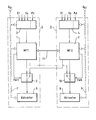
- the reproduced circuit arrangement consists in principle of two complete, independent circuits I, II with the microprocessor systems 1,2, to each of which an input data or input information receiving and detecting circuit 3,4 and an output of the microprocessor systems 1,2 evaluating actuator 5 , 6 belong.
- Another, not indispensable part of the invention scarf processing arrangement is the individual power supply 7.8, which is symbolized here as a supply line to the individual components of the two circuits I, II or microprocessor systems 1.2 shown by dashed double line.
- Circle I, II components of the circuit arrangement according to the invention are summarized in the figure by a dash-dotted frame.
- Everyone Circle I, II contains a complete microprocessor system, including the peripherals.
- circle I thus includes the components 1.3, a switch 9 and the power supply 7, the circuit II, the components 2,4, a switch 10 and the power supply 8.
- a brake system expediently the two circles I, II each to control associated with the brakes of a vehicle diagonal.
- the wheel sensors deliver the most important input variables of the control system. Consequently, the input circuits 3,4 serve to detect the wheel sensor data.
- actuators come valves or, in a brake-by-wire concept, electric motors that operate the individual wheel brakes in question.
- the sources 7,8 can even be supplied from separate vehicle batteries U B1 , U B2 or from separate battery cells.
- the signal paths or data paths from the microprocessor systems 1 and 2 to the associated Aktuatorbetuschisten 5.6 lead according to the illustration in each case via one of the switches 9.10.
- the connection from the microprocessor system 1, 2 to the associated actuator actuator 5, 6 is closed.
- FAIL error detection signal
- the changeover switch 9 or 10 is placed in its second switching position, in which the control of the actuators of the defective circuit I or II is taken from the intact circuit II or I. If all the input data is supplied to the intact microprocessor system, the brake operation can continue unrestrictedly even after the transfer of the changeover switch 9 or 10 and thus after the transition to the emergency function.
- the terminals S1 to S4 of the signal detection 3,4 symbolize the inputs for receiving the wheel sensor data.
- An input Pd is used in a brake-by-wire concept to receive the brake pedal actuation data.
- a unique error detection signal is known to be produced using a microprocessor system with redundant signal processing by comparing the data processing results or intermediate results. If there is an error, the match is no longer present. This signal is evaluated according to the invention for switching to the emergency function.
- the microprocessor systems 1, 2 belonging to the circuits I, II are connected to one another by a communication device 11. This way there is a data exchange, which ensures that all input data and intermediate results of the data processing can be processed and evaluated in both microprocessor systems 1,2.
- various monitoring measures can be implemented in a known manner via this communication device 11.
- a significant advantage of the circuit arrangement according to the invention is that it consists of two identical circuits I, II with redundant data processing.
- Each circuit I or II can be used for a control system in which a mechanical or hydraulic emergency function is given in case of failure when switching off the electronics or the actuator.
- a circuit I or II when a fault occurs, either a circuit I or II is turned off or the actuator actuation of this circuit is taken over by the intact circuit.
- the operation of the switch 9.10 which can be implemented by hardware as well as by software, requires the error detection and identification of the error source or the fault location. In principle, it is possible to make the switching dependent on a majority decision if the data processing takes place in more than two (redundant) ways. In the example described in each of the two microprocessor systems 1,2, the data is processed redundantly, so that each system is capable of error detection and signaling alone. It is sufficient to know in which circuit or microprocessor system the error occurs.
Landscapes
- Engineering & Computer Science (AREA)
- Mechanical Engineering (AREA)
- Transportation (AREA)
- Automation & Control Theory (AREA)
- Regulating Braking Force (AREA)
- Valves And Accessory Devices For Braking Systems (AREA)
- Hardware Redundancy (AREA)
Applications Claiming Priority (3)
| Application Number | Priority Date | Filing Date | Title |
|---|---|---|---|
| DE19717686A DE19717686A1 (de) | 1997-04-28 | 1997-04-28 | Schaltungsanordnung für ein Kraftfahrzeug-Regelungssystem |
| DE19717686 | 1997-04-28 | ||
| PCT/EP1998/000922 WO1998049038A1 (de) | 1997-04-28 | 1998-02-18 | Schaltungsanordnung für ein kraftfahrzeug-regelungssystem |
Publications (2)
| Publication Number | Publication Date |
|---|---|
| EP0979189A1 EP0979189A1 (de) | 2000-02-16 |
| EP0979189B1 true EP0979189B1 (de) | 2006-08-23 |
Family
ID=7827839
Family Applications (1)
| Application Number | Title | Priority Date | Filing Date |
|---|---|---|---|
| EP98906959A Expired - Lifetime EP0979189B1 (de) | 1997-04-28 | 1998-02-18 | Schaltungsanordnung für ein kraftfahrzeug-regelungssystem |
Country Status (5)
| Country | Link |
|---|---|
| US (1) | US6410993B1 (enExample) |
| EP (1) | EP0979189B1 (enExample) |
| JP (1) | JP2001522331A (enExample) |
| DE (2) | DE19717686A1 (enExample) |
| WO (1) | WO1998049038A1 (enExample) |
Cited By (3)
| Publication number | Priority date | Publication date | Assignee | Title |
|---|---|---|---|---|
| US8650440B2 (en) | 2008-01-16 | 2014-02-11 | Freescale Semiconductor, Inc. | Processor based system having ECC based check and access validation information means |
| WO2014117940A1 (de) | 2013-02-01 | 2014-08-07 | Mtu Friedrichshafen Gmbh | Verfahren und anordnung zur steuerung einer brennkraftmaschine mit mindestens zwei steuereinheiten |
| DE202015103949U1 (de) | 2015-07-28 | 2016-11-02 | Rollax Gmbh & Co. Kg | Sitzversteller mit Zusatzverriegelung |
Families Citing this family (84)
| Publication number | Priority date | Publication date | Assignee | Title |
|---|---|---|---|---|
| GB2339869B (en) * | 1998-07-20 | 2002-05-15 | Motorola Ltd | Fault-tolerant electronic braking system |
| DE19835654A1 (de) * | 1998-08-06 | 2000-02-17 | Siemens Ag | Vorrichtung zur Erkennung von Fehlern in elektronischen Baugruppen |
| EP1161664B1 (en) * | 1999-12-15 | 2004-06-16 | Delphi Technologies, Inc. | Electric caliper and steering motor hardware topologies for a safety system |
| WO2001057647A1 (en) * | 2000-02-01 | 2001-08-09 | Delphi Technologies, Inc. | A multi-module control-by-wire architecture |
| DE10036286B4 (de) * | 2000-07-26 | 2009-07-30 | Robert Bosch Gmbh | Hydraulische Fahrzeugbremsanlage |
| DE10041888A1 (de) * | 2000-08-25 | 2002-03-07 | Hella Kg Hueck & Co | Steuergerät für ein Fahrzeug |
| DE10052552A1 (de) * | 2000-10-23 | 2002-04-25 | Bosch Gmbh Robert | System zur Steuerung von Betriebsabläufen |
| DE10066063A1 (de) * | 2000-12-07 | 2002-08-22 | Knorr Bremse Systeme | Spannungsversorgung für Logik- und Leistungselektronik eines Radstellers |
| DE10064673B4 (de) * | 2000-12-22 | 2005-02-24 | Renk Ag | Fehlertolerante elektromechanische Stelleinrichtung |
| EP1231121A3 (de) | 2001-02-13 | 2003-03-05 | Siemens Aktiengesellschaft | Bremssystem zur Bremskraftsteuerung |
| WO2002074596A1 (de) * | 2001-03-15 | 2002-09-26 | Robert Bosch Gmbh | Verfahren zur ansteuerung einer komponente eines verteilten sicherheitsrelevanten systems |
| JP2004519059A (ja) | 2001-03-15 | 2004-06-24 | ローベルト ボッシュ ゲゼルシャフト ミット ベシュレンクテル ハフツング | 分配された安全上重要なシステムのコンポーネントの駆動方法 |
| DE10118262A1 (de) * | 2001-04-12 | 2002-10-17 | Bosch Gmbh Robert | Elektrisches Bremssystem |
| US7597679B2 (en) * | 2002-03-27 | 2009-10-06 | Novo Nordisk A/S | Safety system for an electrically driven medical delivery device and a computer-readable medium |
| DE10223880B4 (de) * | 2002-05-29 | 2004-06-17 | Robert Bosch Gmbh | Verfahren zur gegenseitigen Überwachung von Komponenten eines dezentral verteilten Rechnersystems |
| DE10235527C1 (de) * | 2002-08-03 | 2003-10-09 | Daimler Chrysler Ag | Vorrichtung und Verfahren zur redundanten Spannungsversorgung sicherheitsrelevanter Systeme |
| DE10303383A1 (de) * | 2003-01-29 | 2004-08-05 | Zf Lenksysteme Gmbh | Verfahren und Vorrichtung zur Überwachung des sicheren Betriebs einer Funktionseinheit in einem Kraftfahrzeug |
| DE10335812A1 (de) * | 2003-02-13 | 2004-09-02 | Esg Elektroniksystem- Und Logistik-Gmbh | Modulares uns skalierbares System von Elektronikkomponenten für Fahrzeuge |
| DE10307509A1 (de) * | 2003-02-21 | 2004-09-09 | Knorr-Bremse Systeme für Nutzfahrzeuge GmbH | Modulares elektronisches Bremssystem mit Teil- oder Vollredundanz |
| JP3947974B2 (ja) * | 2003-03-05 | 2007-07-25 | 株式会社デンソー | 乗員保護システム |
| DE10320608B4 (de) | 2003-05-08 | 2005-08-11 | Knorr-Bremse Systeme für Nutzfahrzeuge GmbH | Bremsanlage für Fahrzeuge, insbesondere Nutzfahrzeuge mit mindestens zwei separaten elektronischen Bremssteuerkreisen |
| US6984001B2 (en) * | 2003-09-29 | 2006-01-10 | Haldex Brake Products Ab | Power supply network for brake system |
| US7150506B2 (en) * | 2003-09-29 | 2006-12-19 | Haldex Brake Products Ab | Control network for brake system |
| US7350879B2 (en) * | 2003-09-29 | 2008-04-01 | Haldex Brake Products Ab | Control network for brake system |
| US7359786B2 (en) * | 2003-09-29 | 2008-04-15 | Haldex Brake Products Ab | Control and power supply network for vehicle braking system |
| DE102005005995A1 (de) * | 2004-02-23 | 2006-06-22 | Continental Teves Ag & Co. Ohg | Verfahren und Vorrichtung zum Überwachen von Signalverarbeitungseinheiten für Sensoren |
| DE102004009469A1 (de) * | 2004-02-27 | 2005-09-15 | Daimlerchrysler Ag | Redundantes Bremssteuerungssystem für ein Fahrzeug |
| US7406370B2 (en) | 2004-08-24 | 2008-07-29 | Honeywell International Inc. | Electrical energy management system on a more electric vehicle |
| JP2006336691A (ja) * | 2005-05-31 | 2006-12-14 | Denso Corp | 車両制御システム |
| EP2004473B1 (de) * | 2006-04-03 | 2013-08-14 | ThyssenKrupp Presta Aktiengesellschaft | Überwachungseinrichtung für die funktion einer elektronischen steuerungseinrichtung und verfahren hierzu |
| DE102006053617A1 (de) * | 2006-11-14 | 2008-05-15 | Siemens Ag | System zur Aktorsteuerung, insbesondere Bremssystem |
| JP2008207662A (ja) | 2007-02-26 | 2008-09-11 | Hitachi Ltd | ブレーキ制御装置及びブレーキ制御方法 |
| JP2008230326A (ja) * | 2007-03-19 | 2008-10-02 | Hitachi Ltd | ブレーキ制御装置 |
| DE102007036259A1 (de) * | 2007-08-02 | 2009-02-05 | Robert Bosch Gmbh | Bremssystem für ein Fahrzeug und ein Verfahren zum Betreiben eines Bremssystems für ein Fahrzeug |
| DE102007046706A1 (de) | 2007-09-28 | 2009-04-16 | Autoliv Development Ab | Steuervorrichtung für Fahrzeuge |
| DE102008003381B4 (de) * | 2008-01-07 | 2024-10-02 | Zf Cv Systems Hannover Gmbh | Bremsanlage für ein Fahrzeug |
| GB0802212D0 (en) * | 2008-02-06 | 2008-03-12 | Meritor Heavy Vehicle Braking | A brake system and method |
| DE102008011165B4 (de) * | 2008-02-26 | 2017-05-04 | Autoliv Development Ab | Sensoranordnung für ein Insassenschutzsystem eines Kraftfahrzeugs |
| FR2939749B1 (fr) * | 2008-12-16 | 2011-10-28 | Renault Sas | Systeme de liaison entre organes et capteurs de vehicule automobile a commandes electriques |
| DE102009014642A1 (de) * | 2009-03-24 | 2010-09-30 | Valeo Schalter Und Sensoren Gmbh | Anordnung zur Steuerung eines Fahrzeugassistenzsystems |
| JP5373509B2 (ja) * | 2009-09-02 | 2013-12-18 | トヨタ自動車株式会社 | ブレーキ制御装置 |
| US9145886B2 (en) * | 2011-03-15 | 2015-09-29 | Ford Global Technologies, Llc | Electric vacuum pump backup control system and method |
| EP2537715B1 (en) * | 2011-06-22 | 2018-01-24 | Volvo Car Corporation | Method and arrangement for improving the performance of a electric safety-critical vehicle actuator |
| US20130035772A1 (en) * | 2011-08-05 | 2013-02-07 | General Electric Company | Generator regulating system and method with dual controllers |
| CN103072441B (zh) * | 2011-10-26 | 2015-05-13 | 现代摩比斯株式会社 | 具有故障安全功能的电子控制悬架装置及其控制方法 |
| DE102012204263A1 (de) * | 2012-03-19 | 2013-09-19 | Continental Teves Ag & Co. Ohg | Fremdkraftbremsanlage |
| JP5944718B2 (ja) * | 2012-04-04 | 2016-07-05 | Ntn株式会社 | 電動ブレーキ装置 |
| DE102013213169A1 (de) * | 2013-07-04 | 2015-01-08 | Robert Bosch Gmbh | Verfahren und Vorrichtung zum Betreiben eines Kraftfahrzeugs in einem automatisierten Fahrbetrieb |
| DE102013017688B4 (de) | 2013-10-24 | 2015-03-19 | Audi Ag | Kraftfahrzeug |
| DE102015206572A1 (de) * | 2014-05-15 | 2015-11-19 | Continental Teves Ag & Co. Ohg | Bremsanlage für Kraftfahrzeuge |
| US12509037B2 (en) | 2014-11-13 | 2025-12-30 | Faiveley Transport Italia S.P.A. | Vehicle braking assembly |
| US11498541B2 (en) * | 2015-11-12 | 2022-11-15 | Faiveley Transport Italia S.P.A. | Vehicle braking assembly |
| DE102014226109B4 (de) * | 2014-12-16 | 2022-01-27 | Volkswagen Aktiengesellschaft | Kraftfahrzeug mit Multikollisionsbremsung |
| DE102016112332B4 (de) * | 2016-07-06 | 2021-09-02 | Robert Bosch Gmbh | Verfahren und vorrichtung zum überwachen eines reglerblocks zum ansteuern eines stellantriebs, insbesondere eines stellantriebs eines lenksystems |
| JP6579054B2 (ja) | 2016-07-27 | 2019-09-25 | 株式会社アドヴィックス | センサ監視装置、及び、該装置を備える車両の制動制御装置 |
| JP6634980B2 (ja) * | 2016-07-27 | 2020-01-22 | 株式会社アドヴィックス | 車両の制動制御装置 |
| DE102016225537A1 (de) * | 2016-12-20 | 2018-06-21 | Continental Teves Ag & Co. Ohg | Bremssystem mit zwei Druckquellen und Verfahren zum Betreiben eines Bremssystems |
| JP2018172034A (ja) * | 2017-03-31 | 2018-11-08 | 日信工業株式会社 | 車両用ブレーキシステム |
| KR102353022B1 (ko) * | 2017-05-17 | 2022-01-20 | 주식회사 만도 | 전자식 브레이크 시스템 |
| IT201700059733A1 (it) * | 2017-05-31 | 2018-12-01 | Freni Brembo Spa | Impianto frenante per veicoli di tipo brake by wire munito di simulatore di feedback idraulico, e metodo di attuazione di un impianto frenante per veicoli |
| DE102017113743A1 (de) * | 2017-06-21 | 2018-12-27 | Man Truck & Bus Ag | Druckmittelbetätigte und zumindest teilweise elektronische Bremsvorrichtung |
| DE102017114556A1 (de) * | 2017-06-29 | 2019-01-03 | Ipgate Ag | Vorrichtung für ein hydraulisches Betätigungssystem |
| DE102018002990B4 (de) * | 2018-04-12 | 2025-10-09 | Zf Active Safety Gmbh | Hydraulische Kraftfahrzeug-Bremsanlage und Verfahren zum Betreiben derselben |
| DE102018208223A1 (de) * | 2018-05-24 | 2019-11-28 | Continental Teves & Co. Ohg | Bremssystem mit zwei Druckquellen und Verfahren zum Betreiben eines Bremssystems mit zwei Druckquellen |
| CN109372646B (zh) * | 2018-09-06 | 2021-02-09 | 中车大连机车车辆有限公司 | 燃油泵控制电路及方法 |
| PL3626554T3 (pl) * | 2018-09-18 | 2024-06-17 | Knorr-Bremse Systeme für Nutzfahrzeuge GmbH | System sterowania pojazdem |
| US12472918B2 (en) * | 2019-03-29 | 2025-11-18 | Hl Mando Corporation | Brake system |
| GB2584426B (en) * | 2019-05-28 | 2024-03-27 | Haldex Brake Prod Ab | Vehicle braking system |
| DE102019218005A1 (de) | 2019-11-22 | 2021-05-27 | Robert Bosch Gmbh | LIDAR-Sensor |
| DE102019133011A1 (de) * | 2019-12-04 | 2021-06-10 | Zf Cv Systems Global Gmbh | Monostabil und fehlertolerant ausgelegte Feststellbremsventilanordnung |
| CN110949176B (zh) * | 2019-12-06 | 2020-12-08 | 中国第一汽车股份有限公司 | 冗余供电控制系统及方法 |
| CN114761292A (zh) * | 2019-12-10 | 2022-07-15 | 沃尔沃卡车集团 | 冗余制动装置系统 |
| DE102020200287A1 (de) * | 2020-01-11 | 2021-07-15 | Robert Bosch Gesellschaft mit beschränkter Haftung | Verfahren zur Steuerung der Inbetriebnahme eines elektrisch ansteuerbaren Aktors in einem Kraftfahrzeug und elektronisches Steuergerät zur Durchführung dieses Verfahrens |
| JP7331721B2 (ja) * | 2020-02-07 | 2023-08-23 | トヨタ自動車株式会社 | 自動運転車両の制御装置 |
| US11407394B2 (en) * | 2020-03-09 | 2022-08-09 | Bendix Commercial Vehicle Systems Llc | Method and parking brake apparatus for an autonomously drivable vehicle |
| EP3888983A1 (en) * | 2020-03-31 | 2021-10-06 | Hitachi Astemo Netherlands B.V. | Fail operational electric brake system |
| DE102020206566A1 (de) * | 2020-05-26 | 2021-12-02 | Robert Bosch Gesellschaft mit beschränkter Haftung | Sensoranordnung für ein Fahrzeug und mehrkreisiges Bremssystem |
| WO2022077195A1 (zh) | 2020-10-13 | 2022-04-21 | 华为技术有限公司 | 电子机械制动方法和电子机械制动装置 |
| DE102021209799B4 (de) * | 2021-09-06 | 2025-11-20 | Volkswagen Aktiengesellschaft | Steuerungssystem für eine elektromechanische Aktivierung einer Bremswirkung bei einem Fahrzeug, Fahrzeug, Verfahren sowie Computerprogrammprodukt |
| JP2024051696A (ja) * | 2022-09-30 | 2024-04-11 | 株式会社デンソー | 電動ブレーキシステム |
| DE102023107227A1 (de) | 2023-03-22 | 2024-09-26 | Thyssenkrupp Ag | Elektromechanisches Bremssystem für ein Kraftfahrzeug und Verfahren zum Betreiben eines elektromechanischen Bremssystems in einem Kraftfahrzeug |
| DE102023114602A1 (de) * | 2023-06-02 | 2024-12-05 | Zf Cv Systems Global Gmbh | Redundante Bremsanlage und Anhängefahrzeug |
| KR102810145B1 (ko) * | 2023-06-02 | 2025-05-20 | 에이치엘만도 주식회사 | 브레이크 장치 및 그 제어 방법 |
| WO2025182365A1 (ja) * | 2024-02-27 | 2025-09-04 | Astemo株式会社 | 鞍乗型車両用ブレーキ制御システム |
Family Cites Families (26)
| Publication number | Priority date | Publication date | Assignee | Title |
|---|---|---|---|---|
| DE3024370C2 (de) | 1980-06-27 | 1987-01-02 | Siemens AG, 1000 Berlin und 8000 München | Redundantes Steuersystem |
| DE3225455C2 (de) * | 1982-07-07 | 1986-07-17 | Siemens AG, 1000 Berlin und 8000 München | Verfahren zum sicheren Betrieb eines redundanten Steuersystems |
| DE3234637A1 (de) | 1982-09-18 | 1984-03-22 | Alfred Teves Gmbh, 6000 Frankfurt | Verfahren und schaltungsanordnung zur steuerung einer bremsschlupfregelanlage |
| DE3525455A1 (de) | 1985-07-17 | 1987-01-29 | Helmut Haiges | Gaertemperatur-regelgeraet |
| EP0314698B1 (de) * | 1986-07-19 | 1990-06-27 | ZF FRIEDRICHSHAFEN Aktiengesellschaft | Hilfskraftlenkung, insbesondere für kraftfahrzeuge |
| JPS6377244A (ja) * | 1986-09-19 | 1988-04-07 | Nippon Denso Co Ltd | 通信制御装置 |
| DE3725750A1 (de) * | 1987-08-04 | 1989-02-23 | Vdo Schindling | Mehrprozessorsystem mit wenigstens zwei prozessoren zur erzeugung gleicher oder nahezu gleicher ausgangssignale |
| DE3825280A1 (de) * | 1988-07-26 | 1990-02-01 | Bayerische Motoren Werke Ag | Steuersystem fuer stelleinrichtungen eines kraftfahrzeugs |
| US5074626A (en) * | 1989-05-01 | 1991-12-24 | Rockwell International Corporation | Antilock brake controller |
| GB2241123B (en) * | 1990-02-16 | 1993-09-29 | Teves Gmbh Alfred | Circuit arrangement for an anti-lock-controlled vehicle brake system |
| GB9101227D0 (en) * | 1991-01-19 | 1991-02-27 | Lucas Ind Plc | Method of and apparatus for arbitrating between a plurality of controllers,and control system |
| DE4122016A1 (de) * | 1991-07-03 | 1993-01-21 | Hella Kg Hueck & Co | Antiblockierregelsystem |
| DE4124987A1 (de) * | 1991-07-27 | 1993-01-28 | Bosch Gmbh Robert | System zur ansteuerung sicherheitsrelevanter systeme |
| US5458404A (en) * | 1991-11-12 | 1995-10-17 | Itt Automotive Europe Gmbh | Redundant wheel sensor signal processing in both controller and monitoring circuits |
| DE4201577A1 (de) * | 1992-01-22 | 1993-07-29 | Bosch Gmbh Robert | Elektronisches steuersystem fuer ein elektromagnetisches stellmittel in einem kraftfahrzeug mit einem steuergeraet |
| DE4212337A1 (de) * | 1992-04-13 | 1993-10-14 | Bosch Gmbh Robert | Sicherheitsanlage für ein Fahrzeug |
| DE4326919A1 (de) * | 1993-08-11 | 1995-02-16 | Teves Gmbh Alfred | Regelschaltung für Bremsanlagen mit ABS und/oder ASR |
| DE4339570B4 (de) * | 1993-11-19 | 2004-03-04 | Robert Bosch Gmbh | Elektronisches Bremssystem |
| DE4341082A1 (de) * | 1993-12-02 | 1995-06-08 | Teves Gmbh Alfred | Schaltungsanordnung für sicherheitskritische Regelungssysteme |
| DE4414980A1 (de) * | 1994-04-29 | 1995-11-02 | Teves Gmbh Alfred | Schaltungsanordnung für eine Bremsanlage mit EBV |
| US5490072A (en) * | 1994-07-18 | 1996-02-06 | Kelsey-Hayes Company | Method and system for detecting the proper functioning of an ABS control unit utilizing dual programmed microprocessors |
| DE19509150C2 (de) * | 1995-03-14 | 2003-03-27 | Continental Teves Ag & Co Ohg | Verfahren zum Steuern und Regeln von Fahrzeug-Bremsanlagen sowie Fahrzeug-Bremsanlage |
| DE19529434B4 (de) * | 1995-08-10 | 2009-09-17 | Continental Teves Ag & Co. Ohg | Microprozessorsystem für sicherheitskritische Regelungen |
| DE19607429B4 (de) * | 1996-02-28 | 2004-02-19 | Daimlerchrysler Ag | Fehlertolerante Steuerungseinrichtung für ein physikalisches System, insbesondere Fahrdynamikregeleinrichtung für ein Kraftfahrzeug |
| DE19631309A1 (de) * | 1996-08-02 | 1998-02-05 | Teves Gmbh Alfred | Mikroprozessoranordnung für ein Fahrzeug-Regelungssystem |
| DE19826131A1 (de) * | 1998-06-12 | 1999-12-16 | Bosch Gmbh Robert | Elektrisches Bremssystem für ein Kraftfahrzeug |
-
1997
- 1997-04-28 DE DE19717686A patent/DE19717686A1/de not_active Withdrawn
-
1998
- 1998-02-18 EP EP98906959A patent/EP0979189B1/de not_active Expired - Lifetime
- 1998-02-18 DE DE59813695T patent/DE59813695D1/de not_active Expired - Lifetime
- 1998-02-18 WO PCT/EP1998/000922 patent/WO1998049038A1/de not_active Ceased
- 1998-02-18 US US09/403,876 patent/US6410993B1/en not_active Expired - Fee Related
- 1998-02-18 JP JP54651798A patent/JP2001522331A/ja active Pending
Cited By (7)
| Publication number | Priority date | Publication date | Assignee | Title |
|---|---|---|---|---|
| US8650440B2 (en) | 2008-01-16 | 2014-02-11 | Freescale Semiconductor, Inc. | Processor based system having ECC based check and access validation information means |
| WO2014117940A1 (de) | 2013-02-01 | 2014-08-07 | Mtu Friedrichshafen Gmbh | Verfahren und anordnung zur steuerung einer brennkraftmaschine mit mindestens zwei steuereinheiten |
| DE102013201702A1 (de) | 2013-02-01 | 2014-08-07 | Mtu Friedrichshafen Gmbh | Verfahren und Anordnung zur Steuerung einer Brennkraftmaschine |
| DE102013201702B4 (de) | 2013-02-01 | 2014-11-27 | Mtu Friedrichshafen Gmbh | Verfahren und Anordnung zur Steuerung einer Brennkraftmaschine |
| DE102013201702C5 (de) * | 2013-02-01 | 2017-03-23 | Mtu Friedrichshafen Gmbh | Verfahren und Anordnung zur Steuerung einer Brennkraftmaschine |
| US9719452B2 (en) | 2013-02-01 | 2017-08-01 | Mtu Friedrichshafen Gmbh | Method and arrangement for controlling an internal combustion engine, comprising at least two control units |
| DE202015103949U1 (de) | 2015-07-28 | 2016-11-02 | Rollax Gmbh & Co. Kg | Sitzversteller mit Zusatzverriegelung |
Also Published As
| Publication number | Publication date |
|---|---|
| DE19717686A1 (de) | 1998-10-29 |
| US6410993B1 (en) | 2002-06-25 |
| JP2001522331A (ja) | 2001-11-13 |
| EP0979189A1 (de) | 2000-02-16 |
| WO1998049038A1 (de) | 1998-11-05 |
| DE59813695D1 (de) | 2006-10-05 |
Similar Documents
| Publication | Publication Date | Title |
|---|---|---|
| EP0979189B1 (de) | Schaltungsanordnung für ein kraftfahrzeug-regelungssystem | |
| EP1032517B1 (de) | Elektromechanisches bremssystem | |
| EP0728086B1 (de) | Elektronisches bremssystem | |
| EP1541437B2 (de) | Elektronisches Bremssystem für ein Fahrzeug | |
| EP0976012B1 (de) | Mikroprozessorsystem für sicherheitskritische regelungen | |
| EP0780276B1 (de) | Bremsanlage für ein Kraftfahrzeug | |
| EP1625061B1 (de) | Bremsanlage für fahrzeuge, insbesondere nutzfahrzeuge mit mindestens zwei separaten elektronischen bremssteuerkreisen | |
| EP0981783B1 (de) | Mikroprozessorsystem für kfz-regelungssysteme | |
| DE19634567B4 (de) | Elektrisches Bremssystem | |
| EP1032518B1 (de) | Elektromechanisches bremssystem | |
| DE10043189B4 (de) | Elektrisches Fahrzeugsteuersystem mit einer Eingabevorrichtung, die mit zentralem und peripherem Steuergerät zur Aktuatorsteuerung verbunden ist | |
| DE19832167A1 (de) | Elektromechanisches Bremssystem | |
| DE4334260A1 (de) | Steuervorrichtung für ein Fahrzeug mit einem Antiblockier-Bremssystem und einem Servolenkungs-Steuersystem | |
| EP0789655A1 (de) | Mikroprozessoranordnung für ein fahrzeug-regelungssystem | |
| DE19853036A1 (de) | Elektromechanisches Bremssystem | |
| WO2009152981A1 (de) | Bremsanlage und verfahren zum steuern einer fahrzeugbremse | |
| DE10112514A1 (de) | X-by-wire-System für ein Fahrzeug | |
| DE19937159B4 (de) | Elektrisch gesteuertes Bremssystem | |
| EP1053153B1 (de) | Verfahren zur behandlung von fehlern in einem elektronischen bremssystem und zugehörige vorrichtung | |
| EP0937614A2 (de) | Verfahren und Vorrichtung zur Steuerung einer Bremsanlage | |
| DE19832950B4 (de) | Verfahren zur Behandlung von Fehlern in einem elektronischen Bremssystem und zugehörige Vorrichtung | |
| EP4347338B1 (de) | Elektromechanisches bremssystem für ein kraftfahrzeug, verfahren | |
| EP1213199B1 (de) | Spannungsversorgung für Logik-und Leistungselektronik eines Radstellers |
Legal Events
| Date | Code | Title | Description |
|---|---|---|---|
| PUAI | Public reference made under article 153(3) epc to a published international application that has entered the european phase |
Free format text: ORIGINAL CODE: 0009012 |
|
| 17P | Request for examination filed |
Effective date: 19991129 |
|
| AK | Designated contracting states |
Kind code of ref document: A1 Designated state(s): DE FR GB |
|
| 17Q | First examination report despatched |
Effective date: 20021220 |
|
| GRAP | Despatch of communication of intention to grant a patent |
Free format text: ORIGINAL CODE: EPIDOSNIGR1 |
|
| GRAS | Grant fee paid |
Free format text: ORIGINAL CODE: EPIDOSNIGR3 |
|
| GRAA | (expected) grant |
Free format text: ORIGINAL CODE: 0009210 |
|
| AK | Designated contracting states |
Kind code of ref document: B1 Designated state(s): DE FR GB |
|
| REG | Reference to a national code |
Ref country code: GB Ref legal event code: FG4D Free format text: NOT ENGLISH |
|
| REF | Corresponds to: |
Ref document number: 59813695 Country of ref document: DE Date of ref document: 20061005 Kind code of ref document: P |
|
| GBT | Gb: translation of ep patent filed (gb section 77(6)(a)/1977) |
Effective date: 20060921 |
|
| PLBI | Opposition filed |
Free format text: ORIGINAL CODE: 0009260 |
|
| 26 | Opposition filed |
Opponent name: WABCO GMBH Effective date: 20061026 |
|
| ET | Fr: translation filed | ||
| PLAX | Notice of opposition and request to file observation + time limit sent |
Free format text: ORIGINAL CODE: EPIDOSNOBS2 |
|
| PLBB | Reply of patent proprietor to notice(s) of opposition received |
Free format text: ORIGINAL CODE: EPIDOSNOBS3 |
|
| PLCK | Communication despatched that opposition was rejected |
Free format text: ORIGINAL CODE: EPIDOSNREJ1 |
|
| PLBN | Opposition rejected |
Free format text: ORIGINAL CODE: 0009273 |
|
| STAA | Information on the status of an ep patent application or granted ep patent |
Free format text: STATUS: OPPOSITION REJECTED |
|
| 27O | Opposition rejected |
Effective date: 20091005 |
|
| REG | Reference to a national code |
Ref country code: FR Ref legal event code: PLFP Year of fee payment: 18 |
|
| PGFP | Annual fee paid to national office [announced via postgrant information from national office to epo] |
Ref country code: DE Payment date: 20150228 Year of fee payment: 18 |
|
| PGFP | Annual fee paid to national office [announced via postgrant information from national office to epo] |
Ref country code: FR Payment date: 20150219 Year of fee payment: 18 Ref country code: GB Payment date: 20150218 Year of fee payment: 18 |
|
| REG | Reference to a national code |
Ref country code: DE Ref legal event code: R119 Ref document number: 59813695 Country of ref document: DE |
|
| GBPC | Gb: european patent ceased through non-payment of renewal fee |
Effective date: 20160218 |
|
| REG | Reference to a national code |
Ref country code: FR Ref legal event code: ST Effective date: 20161028 |
|
| PG25 | Lapsed in a contracting state [announced via postgrant information from national office to epo] |
Ref country code: DE Free format text: LAPSE BECAUSE OF NON-PAYMENT OF DUE FEES Effective date: 20160901 Ref country code: FR Free format text: LAPSE BECAUSE OF NON-PAYMENT OF DUE FEES Effective date: 20160229 Ref country code: GB Free format text: LAPSE BECAUSE OF NON-PAYMENT OF DUE FEES Effective date: 20160218 |