EP0979189B1 - Circuit configuration for a motor vehicle control system - Google Patents
Circuit configuration for a motor vehicle control system Download PDFInfo
- Publication number
- EP0979189B1 EP0979189B1 EP98906959A EP98906959A EP0979189B1 EP 0979189 B1 EP0979189 B1 EP 0979189B1 EP 98906959 A EP98906959 A EP 98906959A EP 98906959 A EP98906959 A EP 98906959A EP 0979189 B1 EP0979189 B1 EP 0979189B1
- Authority
- EP
- European Patent Office
- Prior art keywords
- circuit
- circuit arrangement
- systems
- control
- microprocessor
- Prior art date
- Legal status (The legal status is an assumption and is not a legal conclusion. Google has not performed a legal analysis and makes no representation as to the accuracy of the status listed.)
- Expired - Lifetime
Links
- 238000012545 processing Methods 0.000 claims abstract description 17
- 230000004913 activation Effects 0.000 claims abstract 4
- 230000006870 function Effects 0.000 claims description 27
- 230000007704 transition Effects 0.000 claims description 6
- 238000004891 communication Methods 0.000 claims description 5
- 238000000034 method Methods 0.000 claims description 4
- 230000008569 process Effects 0.000 claims description 3
- 238000013461 design Methods 0.000 claims description 2
- 238000011156 evaluation Methods 0.000 claims 3
- 238000001514 detection method Methods 0.000 abstract description 14
- 230000015654 memory Effects 0.000 description 6
- 238000012544 monitoring process Methods 0.000 description 4
- 238000012360 testing method Methods 0.000 description 4
- 230000001276 controlling effect Effects 0.000 description 2
- 230000007257 malfunction Effects 0.000 description 2
- 238000004519 manufacturing process Methods 0.000 description 2
- 230000003213 activating effect Effects 0.000 description 1
- 238000013459 approach Methods 0.000 description 1
- 230000008901 benefit Effects 0.000 description 1
- 230000002950 deficient Effects 0.000 description 1
- 230000001419 dependent effect Effects 0.000 description 1
- 238000012423 maintenance Methods 0.000 description 1
- 230000002093 peripheral effect Effects 0.000 description 1
- 230000009467 reduction Effects 0.000 description 1
- 230000001105 regulatory effect Effects 0.000 description 1
- 230000011664 signaling Effects 0.000 description 1
- 239000000725 suspension Substances 0.000 description 1
- 238000012546 transfer Methods 0.000 description 1
Images
Classifications
-
- B—PERFORMING OPERATIONS; TRANSPORTING
- B60—VEHICLES IN GENERAL
- B60G—VEHICLE SUSPENSION ARRANGEMENTS
- B60G17/00—Resilient suspensions having means for adjusting the spring or vibration-damper characteristics, for regulating the distance between a supporting surface and a sprung part of vehicle or for locking suspension during use to meet varying vehicular or surface conditions, e.g. due to speed or load
- B60G17/015—Resilient suspensions having means for adjusting the spring or vibration-damper characteristics, for regulating the distance between a supporting surface and a sprung part of vehicle or for locking suspension during use to meet varying vehicular or surface conditions, e.g. due to speed or load the regulating means comprising electric or electronic elements
- B60G17/018—Resilient suspensions having means for adjusting the spring or vibration-damper characteristics, for regulating the distance between a supporting surface and a sprung part of vehicle or for locking suspension during use to meet varying vehicular or surface conditions, e.g. due to speed or load the regulating means comprising electric or electronic elements characterised by the use of a specific signal treatment or control method
- B60G17/0185—Resilient suspensions having means for adjusting the spring or vibration-damper characteristics, for regulating the distance between a supporting surface and a sprung part of vehicle or for locking suspension during use to meet varying vehicular or surface conditions, e.g. due to speed or load the regulating means comprising electric or electronic elements characterised by the use of a specific signal treatment or control method for failure detection
-
- B—PERFORMING OPERATIONS; TRANSPORTING
- B60—VEHICLES IN GENERAL
- B60G—VEHICLE SUSPENSION ARRANGEMENTS
- B60G17/00—Resilient suspensions having means for adjusting the spring or vibration-damper characteristics, for regulating the distance between a supporting surface and a sprung part of vehicle or for locking suspension during use to meet varying vehicular or surface conditions, e.g. due to speed or load
- B60G17/015—Resilient suspensions having means for adjusting the spring or vibration-damper characteristics, for regulating the distance between a supporting surface and a sprung part of vehicle or for locking suspension during use to meet varying vehicular or surface conditions, e.g. due to speed or load the regulating means comprising electric or electronic elements
- B60G17/0195—Resilient suspensions having means for adjusting the spring or vibration-damper characteristics, for regulating the distance between a supporting surface and a sprung part of vehicle or for locking suspension during use to meet varying vehicular or surface conditions, e.g. due to speed or load the regulating means comprising electric or electronic elements characterised by the regulation being combined with other vehicle control systems
-
- B—PERFORMING OPERATIONS; TRANSPORTING
- B60—VEHICLES IN GENERAL
- B60T—VEHICLE BRAKE CONTROL SYSTEMS OR PARTS THEREOF; BRAKE CONTROL SYSTEMS OR PARTS THEREOF, IN GENERAL; ARRANGEMENT OF BRAKING ELEMENTS ON VEHICLES IN GENERAL; PORTABLE DEVICES FOR PREVENTING UNWANTED MOVEMENT OF VEHICLES; VEHICLE MODIFICATIONS TO FACILITATE COOLING OF BRAKES
- B60T17/00—Component parts, details, or accessories of power brake systems not covered by groups B60T8/00, B60T13/00 or B60T15/00, or presenting other characteristic features
- B60T17/18—Safety devices; Monitoring
- B60T17/22—Devices for monitoring or checking brake systems; Signal devices
- B60T17/221—Procedure or apparatus for checking or keeping in a correct functioning condition of brake systems
-
- B—PERFORMING OPERATIONS; TRANSPORTING
- B60—VEHICLES IN GENERAL
- B60T—VEHICLE BRAKE CONTROL SYSTEMS OR PARTS THEREOF; BRAKE CONTROL SYSTEMS OR PARTS THEREOF, IN GENERAL; ARRANGEMENT OF BRAKING ELEMENTS ON VEHICLES IN GENERAL; PORTABLE DEVICES FOR PREVENTING UNWANTED MOVEMENT OF VEHICLES; VEHICLE MODIFICATIONS TO FACILITATE COOLING OF BRAKES
- B60T8/00—Arrangements for adjusting wheel-braking force to meet varying vehicular or ground-surface conditions, e.g. limiting or varying distribution of braking force
- B60T8/32—Arrangements for adjusting wheel-braking force to meet varying vehicular or ground-surface conditions, e.g. limiting or varying distribution of braking force responsive to a speed condition, e.g. acceleration or deceleration
- B60T8/321—Arrangements for adjusting wheel-braking force to meet varying vehicular or ground-surface conditions, e.g. limiting or varying distribution of braking force responsive to a speed condition, e.g. acceleration or deceleration deceleration
-
- B—PERFORMING OPERATIONS; TRANSPORTING
- B60—VEHICLES IN GENERAL
- B60T—VEHICLE BRAKE CONTROL SYSTEMS OR PARTS THEREOF; BRAKE CONTROL SYSTEMS OR PARTS THEREOF, IN GENERAL; ARRANGEMENT OF BRAKING ELEMENTS ON VEHICLES IN GENERAL; PORTABLE DEVICES FOR PREVENTING UNWANTED MOVEMENT OF VEHICLES; VEHICLE MODIFICATIONS TO FACILITATE COOLING OF BRAKES
- B60T8/00—Arrangements for adjusting wheel-braking force to meet varying vehicular or ground-surface conditions, e.g. limiting or varying distribution of braking force
- B60T8/32—Arrangements for adjusting wheel-braking force to meet varying vehicular or ground-surface conditions, e.g. limiting or varying distribution of braking force responsive to a speed condition, e.g. acceleration or deceleration
- B60T8/88—Arrangements for adjusting wheel-braking force to meet varying vehicular or ground-surface conditions, e.g. limiting or varying distribution of braking force responsive to a speed condition, e.g. acceleration or deceleration with failure responsive means, i.e. means for detecting and indicating faulty operation of the speed responsive control means
- B60T8/885—Arrangements for adjusting wheel-braking force to meet varying vehicular or ground-surface conditions, e.g. limiting or varying distribution of braking force responsive to a speed condition, e.g. acceleration or deceleration with failure responsive means, i.e. means for detecting and indicating faulty operation of the speed responsive control means using electrical circuitry
-
- B—PERFORMING OPERATIONS; TRANSPORTING
- B60—VEHICLES IN GENERAL
- B60T—VEHICLE BRAKE CONTROL SYSTEMS OR PARTS THEREOF; BRAKE CONTROL SYSTEMS OR PARTS THEREOF, IN GENERAL; ARRANGEMENT OF BRAKING ELEMENTS ON VEHICLES IN GENERAL; PORTABLE DEVICES FOR PREVENTING UNWANTED MOVEMENT OF VEHICLES; VEHICLE MODIFICATIONS TO FACILITATE COOLING OF BRAKES
- B60T8/00—Arrangements for adjusting wheel-braking force to meet varying vehicular or ground-surface conditions, e.g. limiting or varying distribution of braking force
- B60T8/32—Arrangements for adjusting wheel-braking force to meet varying vehicular or ground-surface conditions, e.g. limiting or varying distribution of braking force responsive to a speed condition, e.g. acceleration or deceleration
- B60T8/88—Arrangements for adjusting wheel-braking force to meet varying vehicular or ground-surface conditions, e.g. limiting or varying distribution of braking force responsive to a speed condition, e.g. acceleration or deceleration with failure responsive means, i.e. means for detecting and indicating faulty operation of the speed responsive control means
- B60T8/92—Arrangements for adjusting wheel-braking force to meet varying vehicular or ground-surface conditions, e.g. limiting or varying distribution of braking force responsive to a speed condition, e.g. acceleration or deceleration with failure responsive means, i.e. means for detecting and indicating faulty operation of the speed responsive control means automatically taking corrective action
- B60T8/96—Arrangements for adjusting wheel-braking force to meet varying vehicular or ground-surface conditions, e.g. limiting or varying distribution of braking force responsive to a speed condition, e.g. acceleration or deceleration with failure responsive means, i.e. means for detecting and indicating faulty operation of the speed responsive control means automatically taking corrective action on speed responsive control means
-
- B—PERFORMING OPERATIONS; TRANSPORTING
- B60—VEHICLES IN GENERAL
- B60G—VEHICLE SUSPENSION ARRANGEMENTS
- B60G2600/00—Indexing codes relating to particular elements, systems or processes used on suspension systems or suspension control systems
- B60G2600/08—Failure or malfunction detecting means
-
- B—PERFORMING OPERATIONS; TRANSPORTING
- B60—VEHICLES IN GENERAL
- B60G—VEHICLE SUSPENSION ARRANGEMENTS
- B60G2800/00—Indexing codes relating to the type of movement or to the condition of the vehicle and to the end result to be achieved by the control action
- B60G2800/80—Detection or control after a system or component failure
-
- B—PERFORMING OPERATIONS; TRANSPORTING
- B60—VEHICLES IN GENERAL
- B60T—VEHICLE BRAKE CONTROL SYSTEMS OR PARTS THEREOF; BRAKE CONTROL SYSTEMS OR PARTS THEREOF, IN GENERAL; ARRANGEMENT OF BRAKING ELEMENTS ON VEHICLES IN GENERAL; PORTABLE DEVICES FOR PREVENTING UNWANTED MOVEMENT OF VEHICLES; VEHICLE MODIFICATIONS TO FACILITATE COOLING OF BRAKES
- B60T2270/00—Further aspects of brake control systems not otherwise provided for
- B60T2270/40—Failsafe aspects of brake control systems
- B60T2270/413—Plausibility monitoring, cross check, redundancy
-
- B—PERFORMING OPERATIONS; TRANSPORTING
- B60—VEHICLES IN GENERAL
- B60W—CONJOINT CONTROL OF VEHICLE SUB-UNITS OF DIFFERENT TYPE OR DIFFERENT FUNCTION; CONTROL SYSTEMS SPECIALLY ADAPTED FOR HYBRID VEHICLES; ROAD VEHICLE DRIVE CONTROL SYSTEMS FOR PURPOSES NOT RELATED TO THE CONTROL OF A PARTICULAR SUB-UNIT
- B60W50/00—Details of control systems for road vehicle drive control not related to the control of a particular sub-unit, e.g. process diagnostic or vehicle driver interfaces
- B60W50/02—Ensuring safety in case of control system failures, e.g. by diagnosing, circumventing or fixing failures
- B60W50/0205—Diagnosing or detecting failures; Failure detection models
- B60W2050/021—Means for detecting failure or malfunction
Definitions
- the invention relates to a circuit arrangement which is provided for a motor vehicle control system for safety-critical regulations, such as ABS, TCS, ASMS, brake-by-wire, chassis regulations, etc., and has a microcomputer system, which the input data or input information of Processed control system and provides an error detection signal when an error occurs.
- safety-critical regulations such as ABS, TCS, ASMS, brake-by-wire, chassis regulations, etc.
- the safety-critical regulations of this kind include u.a. the engaging in the braking function of a motor vehicle control systems that are in great numbers and great variety in the market. Examples of this are the anti-lock braking systems (ABS), traction control systems (ASR), driving stability regulations (FDR, ASMS), suspension control systems etc.
- ABS anti-lock braking systems
- ASR traction control systems
- FDR driving stability regulations
- ASMS suspension control systems etc.
- a failure of such a control system leads to a threat to the driving stability of the vehicle. Therefore, the functionality of the systems is constantly monitored to be able to switch off the control or to switch to a less dangerous for safety status when an error occurs.
- brake systems or motor vehicle control systems in which, in case of failure of the electronics circuit to a mechanical or hydraulic system is not possible, please include.
- brake system concepts such as “brake-by-wire”, which are expected to become even more important in the future; The brake function relies on intact electronics in such systems.
- the input data are also two microcomputers supplied in parallel, of which, however, only one executes the complete, complex signal processing.
- the second Mi crocomputer primarily serves for monitoring, which is why the input signals using simplified control algorithms and simplified control philosophy can be further processed.
- the simplified data processing is sufficient for the generation of signals which allow conclusions to be drawn on the proper operation of the system by comparison with the signals processed in the more complex microcomputer.
- a microprocessor system is already known, which is provided in particular for the control system of a blokkiergekarten brake system.
- This known system which can be accommodated on a single chip, contains two central units in which the input data are processed in parallel.
- the read-only memories and the read-write memories connected to the two central units contain additional memory spaces for Test information and each include a generator for generating test information.
- the output signals of one of the two central units are further processed to generate the control signals, while the other serves as a passive central unit only for monitoring the active central processing unit.
- a microprocessor system in which two synchronously operated central units are arranged on one or more chips, which receive the same input information and process the same program.
- the two central units are connected via separate bus systems to the read-only memory and to the read-write memory as well as to input and output units.
- the bus systems are interconnected by bypasses which allow the two central units to jointly read and execute the available data, including the test data or redundancy data, and the instructions.
- This known, based on redundant data processing system allows a saving of memory locations, which in turn leads to a reduction of manufacturing costs.
- the present invention is based on the object to develop a circuit arrangement that requires at most little extra effort compared to the known methods described and yet allows the occurrence of an error transition into a limp home function.
- the circuit arrangement is constructed in two or more circuits, each circuit containing a complete microprocessor system which processes the input data or input information and provides an error detection signal when an error occurs; when fault detection is then a transition to a limp home function.
- the input data of this system are redundantly processed and the data processing results or intermediate results are compared, and the error detection signal is generated when deviations occur between the results.
- the circuit arrangement according to the invention can be very easily based on known circuits, e.g. the previously described known systems or circuits that provide an error detection signal implement. It is important that not only the occurrence of an error is signaled, but that it is also recognizable, which system or which circle is faulty or still intact.
- each circuit or each microprocessor system is supplied with all the input data directly or via communication units connecting the individual microprocessor systems, and in the event of a circuit failure activating the actuator in one of the intact circuits will continue the actuator control in the emergency function without any restrictions.
- the illustrated circuit arrangement is suitable, for example, for controlling and regulating a blockage-protected motor vehicle brake system and, in particular, a purely electrical brake system constructed according to the brake-by-wire concept.
- a shutdown of the electronics and "relapse" in a (hydraulic or mechanical) basic function is in principle not possible with such braking systems that operate purely electrically. Consequently, when an error occurs, a limp-home function, which allows a further brake operation, is absolutely necessary.
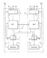
- the reproduced circuit arrangement consists in principle of two complete, independent circuits I, II with the microprocessor systems 1,2, to each of which an input data or input information receiving and detecting circuit 3,4 and an output of the microprocessor systems 1,2 evaluating actuator 5 , 6 belong.
- Another, not indispensable part of the invention scarf processing arrangement is the individual power supply 7.8, which is symbolized here as a supply line to the individual components of the two circuits I, II or microprocessor systems 1.2 shown by dashed double line.
- Circle I, II components of the circuit arrangement according to the invention are summarized in the figure by a dash-dotted frame.
- Everyone Circle I, II contains a complete microprocessor system, including the peripherals.
- circle I thus includes the components 1.3, a switch 9 and the power supply 7, the circuit II, the components 2,4, a switch 10 and the power supply 8.
- a brake system expediently the two circles I, II each to control associated with the brakes of a vehicle diagonal.
- the wheel sensors deliver the most important input variables of the control system. Consequently, the input circuits 3,4 serve to detect the wheel sensor data.
- actuators come valves or, in a brake-by-wire concept, electric motors that operate the individual wheel brakes in question.
- the sources 7,8 can even be supplied from separate vehicle batteries U B1 , U B2 or from separate battery cells.
- the signal paths or data paths from the microprocessor systems 1 and 2 to the associated Aktuatorbetuschisten 5.6 lead according to the illustration in each case via one of the switches 9.10.
- the connection from the microprocessor system 1, 2 to the associated actuator actuator 5, 6 is closed.
- FAIL error detection signal
- the changeover switch 9 or 10 is placed in its second switching position, in which the control of the actuators of the defective circuit I or II is taken from the intact circuit II or I. If all the input data is supplied to the intact microprocessor system, the brake operation can continue unrestrictedly even after the transfer of the changeover switch 9 or 10 and thus after the transition to the emergency function.
- the terminals S1 to S4 of the signal detection 3,4 symbolize the inputs for receiving the wheel sensor data.
- An input Pd is used in a brake-by-wire concept to receive the brake pedal actuation data.
- a unique error detection signal is known to be produced using a microprocessor system with redundant signal processing by comparing the data processing results or intermediate results. If there is an error, the match is no longer present. This signal is evaluated according to the invention for switching to the emergency function.
- the microprocessor systems 1, 2 belonging to the circuits I, II are connected to one another by a communication device 11. This way there is a data exchange, which ensures that all input data and intermediate results of the data processing can be processed and evaluated in both microprocessor systems 1,2.
- various monitoring measures can be implemented in a known manner via this communication device 11.
- a significant advantage of the circuit arrangement according to the invention is that it consists of two identical circuits I, II with redundant data processing.
- Each circuit I or II can be used for a control system in which a mechanical or hydraulic emergency function is given in case of failure when switching off the electronics or the actuator.
- a circuit I or II when a fault occurs, either a circuit I or II is turned off or the actuator actuation of this circuit is taken over by the intact circuit.
- the operation of the switch 9.10 which can be implemented by hardware as well as by software, requires the error detection and identification of the error source or the fault location. In principle, it is possible to make the switching dependent on a majority decision if the data processing takes place in more than two (redundant) ways. In the example described in each of the two microprocessor systems 1,2, the data is processed redundantly, so that each system is capable of error detection and signaling alone. It is sufficient to know in which circuit or microprocessor system the error occurs.
Abstract
Description
Die Erfindung bezieht sich auf eine Schaltungsanordnung, die für ein Kraftfahrzeug-Regelungssystem für sicherheitskritische Regelungen, wie ABS, ASR, ASMS, Brake-by-wire, Fahrwerksregelungen etc., vorgesehen ist und ein Mikrocomputer-System aufweist, welches die Eingangsdaten oder Eingangsinformationen des Regelungssystems verarbeitet und bei Auftreten eines Fehlers ein Fehlererkennungssignal liefert.The invention relates to a circuit arrangement which is provided for a motor vehicle control system for safety-critical regulations, such as ABS, TCS, ASMS, brake-by-wire, chassis regulations, etc., and has a microcomputer system, which the input data or input information of Processed control system and provides an error detection signal when an error occurs.
Zu den sicherheitskritischen Regelungen dieser Art zählen u.a. die in die Bremsenfunktion eines Kraftfahrzeugs eingreifenden Regelungssysteme, die in großer Anzahl und großer Vielfalt auf dem Markt sind. Beispiele hierfür sind die Antiblockiersysteme (ABS), Antriebsschlupfregelungssysteme (ASR), Fahrstabilitätsregelungen (FDR,ASMS), Fahrwerksregelungssysteme etc. Ein Ausfall eines solchen Regelungssystems führt zur Gefährdung der Fahrstabilität des Fahrzeugs. Daher wird die Funktionsfähigkeit der Systeme ständig überwacht, um beim Auftreten eines Fehlers die Regelung abschalten oder in einen für die Sicherheit weniger gefährlichen Zustand umschalten zu können.The safety-critical regulations of this kind include u.a. the engaging in the braking function of a motor vehicle control systems that are in great numbers and great variety in the market. Examples of this are the anti-lock braking systems (ABS), traction control systems (ASR), driving stability regulations (FDR, ASMS), suspension control systems etc. A failure of such a control system leads to a threat to the driving stability of the vehicle. Therefore, the functionality of the systems is constantly monitored to be able to switch off the control or to switch to a less dangerous for safety status when an error occurs.
Noch kritischer sind Bremssysteme bzw. Kraftfahrzeug-Regelungssysteme, bei denen bei Ausfall der Elektronik keine Um schaltung auf ein mechanisches oder hydraulisches System mög lich ist. Hierzu zählen Bremssystemkonzepte, wie "Brake-by-wire", die voraussichtlich in der Zukunft noch an Bedeutung gewinnen werden; die Bremsenfunktion ist bei solchen Systemen auf eine intakte Elektronik angewiesen.Even more critical are brake systems or motor vehicle control systems, in which, in case of failure of the electronics circuit to a mechanical or hydraulic system is not possible, please include. These include brake system concepts, such as "brake-by-wire", which are expected to become even more important in the future; The brake function relies on intact electronics in such systems.
Ein Beispiel für eine Schaltungsanordnung zur Steuerung und Überwachung einer blockiergeschützten Fahrzeugbremsanlage der eingangs genannten Art ist aus der gattungsgemäßen DE 32 34 637 C2 bekannt. Mit dieser Schaltung werden die Eingangsdaten des Kfz- Regelungssystems in zwei identisch programmierten Mikrocomputern parallel und synchron verarbeitet, um durch Vergleich der Ausgangsdaten beider Systeme eine ordnungsgemäße Funktion und das Auftreten von Fehlern erkennen zu können; bei ordnungsgemäßer Datenverarbeitung müssen nämlich an den Ausgängen beider Mikrocomputer identischen Signale anliegen. Beim Auftreten einer Störung oder Fehlfunktion, d.h. bei voneinander abweichenden Ausgangssignalen, wird dann das gesamte Regelungssystem abgeschaltet. Eine solche Vorgehensweise, nämlich das vollständige Abschalten der Regelung beim Auftreten eines Fehlers, setzt voraus, daß auch nach dem Abschalten der Regelung die Bremsenanlage sicher funktioniert, wenn auch ungeregelt.An example of a circuit arrangement for controlling and monitoring an anti-lock vehicle brake system of the type mentioned is known from the generic DE 32 34 637 C2. With this circuit, the input data of the vehicle control system in two identically programmed microcomputers are processed in parallel and synchronously in order to be able to recognize a proper function and the occurrence of errors by comparing the output data of both systems. in the case of proper data processing, identical signals must be present at the outputs of both microcomputers. When a malfunction or malfunction occurs, i. for divergent output signals, then the entire control system is switched off. Such an approach, namely the complete shutdown of the control when an error occurs, requires that even after switching off the control, the brake system works safely, although unregulated.
Nach einem anderen, aus der DE 41 37 124 A1 bekannten System, werden die Eingangsdaten ebenfalls zwei Microcomputern parallel zugeführt, von denen jedoch nur einer die vollständige, aufwendige Signalverarbeitung ausführt. Der zweite Mi crocomputer dient vornehmlich zur Überwachung, weshalb die Eingangssignale mit Hilfe vereinfachter Regelalgorithmen und vereinfachter Regelphilosophie weiterverarbeitet werden können. Die vereinfachte Datenverarbeitung reicht zur Erzeugung von Signalen aus, die durch Vergleich mit den in dem aufwendigeren Microcomputer verarbeiteten Signalen Rückschlüsse auf den ordnungsgemäßen Betrieb des Systems zulassen. Durch die Verwendung eines Prüf-Microcomputers geringerer Leistungsfähigkeit läßt sich der Herstellungsaufwand im Vergleich zu einem System mit zwei vollständigen, aufwendigen Microcomputern gleicher Leistung reduzieren.According to another, known from DE 41 37 124 A1 known system, the input data are also two microcomputers supplied in parallel, of which, however, only one executes the complete, complex signal processing. The second Mi crocomputer primarily serves for monitoring, which is why the input signals using simplified control algorithms and simplified control philosophy can be further processed. The simplified data processing is sufficient for the generation of signals which allow conclusions to be drawn on the proper operation of the system by comparison with the signals processed in the more complex microcomputer. By using a test microcomputer of lower performance, the manufacturing cost can be compared to reduce a system with two complete, complex microcomputers of the same power.
Aus der DE 43 41 082 A1 ist bereits ein Mikroprozessorsystem bekannt, das insbesondere für das Regelsystem einer blokkiergeschützten Bremsanlage vorgesehen ist. Dieses bekannte System, das auf einem einzigen Chip untergebracht werden kann, enthält zwei Zentraleinheiten, in denen die Eingangsdaten parallel verarbeitet werden. Die Festwert- und die Schreib-Lese-Speicher, die an die beiden Zentraleinheiten angeschlossen sind, enthalten zusätzliche Speicherplätze für Prüfinformationen und umfassen jeweils einen Generator zur Erzeugung von Prüfinformationen. Die Ausgangssignale eines der beiden Zentraleinheiten werden zur Erzeugung der Steuersignale weiterverarbeitet, während die andere als passive Zentraleinheit lediglich zur Überwachung der aktiven Zentraleinheit dient.From DE 43 41 082 A1 a microprocessor system is already known, which is provided in particular for the control system of a blokkiergeschützten brake system. This known system, which can be accommodated on a single chip, contains two central units in which the input data are processed in parallel. The read-only memories and the read-write memories connected to the two central units contain additional memory spaces for Test information and each include a generator for generating test information. The output signals of one of the two central units are further processed to generate the control signals, while the other serves as a passive central unit only for monitoring the active central processing unit.
Schließlich ist aus der DE 195 29 434 A1 ein Mikroprozessorsystem bekannt, bei dem auf einem oder auf mehreren Chips zwei synchron betriebene Zentraleinheiten angeordnet sind, die die gleichen Eingangsinformationen erhalten und das gleiche Programm abarbeiten. Die beiden Zentraleinheiten sind über separate Bus-Systeme an die Festwert- und an die Schreib-Lese-Speicher sowie an Eingabe- und Ausgabeeinheiten angeschlossen. Die Bus-Systeme sind untereinander durch Bypässe verbunden, die den beiden Zentraleinheiten ein gemeinsames Lesen und Abarbeiten der zur Verfügung stehenden Daten, einschließlich der Prüfdaten oder Redundanzdaten, und der Befehle ermöglichen. Dieses bekannte, auf redundante Datenverarbeitung beruhende System ermöglicht eine Einsparung von Speicherplätzen, was wiederum zu einer Reduzierung des Herstellungsaufwandes führt.Finally, from DE 195 29 434 A1 a microprocessor system is known in which two synchronously operated central units are arranged on one or more chips, which receive the same input information and process the same program. The two central units are connected via separate bus systems to the read-only memory and to the read-write memory as well as to input and output units. The bus systems are interconnected by bypasses which allow the two central units to jointly read and execute the available data, including the test data or redundancy data, and the instructions. This known, based on redundant data processing system allows a saving of memory locations, which in turn leads to a reduction of manufacturing costs.
Alle vorgenannten Systeme beruhen grundsätzlich auf dem Vergleich redundant verarbeiteter Daten und der Erzeugung eines Fehlersignals, wenn Abweichungen zwischen den Datenverarbeitungsergebnissen oder -zwischenergebnissen auftreten. Bei Fehlererkennung, d.h. bei Auftreten eines Fehlers oder Ausfall eines Systems, wird dann die Regelung abgeschaltet. In keinem Fall ist eine Notlauffunktion, nämlich eine Fortsetzung der Regelung nach dem Auftreten des Fehlers, möglich, weil bei der beschriebenen Art der Fehlererkennung nicht festgestellt werden kann, welches System noch intakt ist. Eine Notlauffunktion auf Basis solcher bekannten Schaltungen wäre grundsätzlich nur durch Verdoppelung der redundanten Systeme in Verbindung mit einem Identifizieren und Abschalten der Fehlerquelle denkbar.All of the above systems are fundamentally based on the comparison of redundantly processed data and the generation of an error signal when deviations occur between the data processing results or intermediate results. When fault detection, ie when an error or failure of a system, then the control is turned off. In no case is an emergency function, namely a continuation of the control after the occurrence of the error, possible because it can not be determined in the described type of error detection, which system is still intact. An emergency function based on such known circuits would basically only by doubling the redundant Systems in connection with identifying and switching off the source of error conceivable.
Der vorliegenden Erfindung liegt nun die Aufgabe zugrunde, eine Schaltungsanordnung zu entwickeln, die im Vergleich zu den beschriebenen bekannten Verfahren höchstens geringen Mehraufwand erfordert und die dennoch beim Auftreten eines Fehlers einen Übergang in eine Notlauffunktion zuläßt.The present invention is based on the object to develop a circuit arrangement that requires at most little extra effort compared to the known methods described and yet allows the occurrence of an error transition into a limp home function.
Es hat sich herausgestellt, daß diese Aufgabe durch die im Anspruch 1 beschriebene Schaltungsanordnung gelöst werden kann. Nach den kennzeichnenden Merkmalen der Erfindung ist die Schaltungsanordnung zwei- oder mehrkreisig aufgebaut, wobei jeder Kreis ein komplettes Mikroprozessorsystem enthält, welches die Eingangsdaten oder Eingangsinformationen verarbeitet und bei Auftreten eines Fehlers ein Fehlererkennungssignal liefert; bei Fehlererkennung erfolgt dann ein Übergang in eine Notlauffunktion.It has been found that this object can be achieved by the circuit arrangement described in
Nach einem besonders vorteilhaften Ausführungsbeispiel der Erfindung werden in jedem Mikroprozessorsystem die Eingangsdaten dieses Systems redundant verarbeitet und die Datenverarbeitungsergebnisse oder Zwischenergebnisse verglichen, und es wird beim Auftreten von Abweichungen zwischen den Ergebnissen das Fehlererkennungssignal erzeugt.According to a particularly advantageous embodiment of the invention, in each microprocessor system, the input data of this system are redundantly processed and the data processing results or intermediate results are compared, and the error detection signal is generated when deviations occur between the results.
Die erfindungsgemäße Schaltungsanordnung läßt sich sehr einfach auf Basis bekannter Schaltungen, z.B. der zuvor geschilderten bekannten Systeme oder Schaltungen, die ein Fehlererkennungssignal liefern, realisieren. Wichtig ist, daß nicht nur das Auftreten eines Fehlers signalisiert wird, sondern daß auch erkennbar ist, welches System oder welcher Kreis fehlerbehaftet bzw. weiterhin intakt ist.The circuit arrangement according to the invention can be very easily based on known circuits, e.g. the previously described known systems or circuits that provide an error detection signal implement. It is important that not only the occurrence of an error is signaled, but that it is also recognizable, which system or which circle is faulty or still intact.
Nach einem weiteren Ausführungsbeispiel der Erfindung werden jedem Kreis oder Mikroprozessorsystem nur die für den betreffenden Kreis benötigten Eingangsdaten zugeführt. Bei Ausfall des Kreises und Übergang in die Notlauffunktion fällt dann der Kreis, in dem der Fehler auftrat, aus. Die Aktuatoren des betreffenden Kreises werden nicht mehr angesteuert. Handelt es sich beispielsweise um eine Kraftfahrzeug-Bremsanlage mit diagonaler Bremsaufteilung, genügt es, in der Notlauffunktion die Bremsen eines Kreises zu betätigen. Es entsteht die gleiche Situation wie beim Ausfall eines hydraulischen Bremskreises einer bekannten, zweikreisigen Bremsanlage mit diagonaler Aufteilung.According to another embodiment of the invention For each circuit or microprocessor system, only the input data needed for the particular circuit is supplied. If the circuit fails and enters the emergency function, the circuit in which the error occurred fails. The actuators of the circle in question are no longer activated. For example, if it is a motor vehicle brake system with diagonal brake distribution, it is sufficient to actuate the brakes of a circle in the emergency function. The result is the same situation as in the case of failure of a hydraulic brake circuit of a known, dual-circuit brake system with diagonal division.
Gemäß der Erfindung werden jedem Kreis oder jedem Mikroprozessorsystem alle Eingangsdaten direkt oder über Kommunikationseinheiten, die die einzelnen Mikroprozessorsystemen verbinden, zugeführt und bei Ausfall eines Kreises wird durch Anschalten der Aktuatorbetätigung an einen der intakten Kreise die Aktuatoransteuerung in der Notlauffunktion ohne Einschränkungen fortgesetzt.According to the invention, each circuit or each microprocessor system is supplied with all the input data directly or via communication units connecting the individual microprocessor systems, and in the event of a circuit failure activating the actuator in one of the intact circuits will continue the actuator control in the emergency function without any restrictions.
Auch hat es sich als zweckmäßig erwiesen, die erfindungsgemäße Schaltungsanordnung für eine Kombination von mehreren Kraftfahrzeug-Regelungssystemen, wie Brake-by-wire, ABS, ASR, ASMS etc., auszulegen, wobei die Notlauffunktion entweder die Aufrechterhaltung des Betriebs aller Regelungssysteme oder nur die Aufrechterhaltung des Betriebs ausgewählter Regelungsfunktionen, z.B. besonders sicherheitskritischer Funktionen, erfaßt. Dabei ist es vorteilhaft, wenn im Fehlerfall diese speziellen Funktionen durch die intakten Kreise übernommen werden.It has also proven to be expedient to design the circuit arrangement according to the invention for a combination of several motor vehicle control systems, such as brake-by-wire, ABS, ASR, ASMS, etc., wherein the emergency function either the maintenance of the operation of all control systems or only the Maintaining the operation of selected control functions, eg particularly safety-critical functions. It is advantageous if, in the event of an error, these special functions are taken over by the intact circuits.
Einige weitere Ausführungsbeispiele sind in den Unteransprüchen beschrieben.Some further embodiments are described in the subclaims.
Aus der beigefügten Abbildung, die in schematisch vereinfachter Darstellung die wichtigsten Komponenten einer Schaltungsanordnung nach der Erfindung wiedergibt, und aus der folgenden Erläuterung gehen weitere Einzelheiten der Erfindung sowie der prinzipielle Aufbau und die Wirkungsweise einer Schaltungsanordnung nach der Erfindung hervor.From the accompanying drawing, which shows in schematic simplified representation of the most important components of a circuit arrangement according to the invention, and from the following explanation, further details of the invention and the basic structure and operation of a circuit arrangement according to the invention will become apparent.
Die dargestellte Schaltungsanordnung ist beispielsweise zur Steuerung und Regelung einer blockiergeschützten Kraftfahrzeug-Bremsanlage und insbesondere einer rein elektrischen, nach dem Brake-by-Wire-Konzept aufgebauten Bremsanlage geeignet. Eine Abschaltung der Elektronik und "Rückfall" in eine (hydraulische oder mechanische)Grundfunktion ist bei solchen Bremsanlagen, die rein elektrisch funktionieren, prinzipbedingt nicht möglich. Beim Auftreten eines Fehlers ist folglich eine Notlauffunktion, die eine weitere Bremsbetätigung zuläßt, unbedingt notwendig.The illustrated circuit arrangement is suitable, for example, for controlling and regulating a blockage-protected motor vehicle brake system and, in particular, a purely electrical brake system constructed according to the brake-by-wire concept. A shutdown of the electronics and "relapse" in a (hydraulic or mechanical) basic function is in principle not possible with such braking systems that operate purely electrically. Consequently, when an error occurs, a limp-home function, which allows a further brake operation, is absolutely necessary.
Die wiedergegebene Schaltungsanordnung besteht im Prinzip aus zwei vollständigen, voneinander unabhängigen Kreisen I, II mit den Mikroprozessorsystemen 1,2, zu denen jeweils auch eine Eingangsdaten oder Eingangsinformationen aufnehmende und erfassende Schaltung 3,4 sowie eine die Ausgangssignale der Mikroprozessorsysteme 1,2 auswertende Aktuatorbetätigung 5,6 gehören. Ein weiterer, nicht verzichtbarer Bestandteil der erfindungsgemäßen Schal tungsanordnung ist die individuelle Energieversorgung 7,8, die hier als Zuführungsleitung zu den einzelnen Komponenten der beiden dargestellten Kreise I,II oder Mikroprozessorsystemen 1,2 durch gestrichelte Doppellinie symbolisiert ist.The reproduced circuit arrangement consists in principle of two complete, independent circuits I, II with the
Die zusammen einen Kreis I,II bildenden Komponenten der erfindungsgemäßen Schaltungsanordnung sind in der Abbildung durch einen strich-punktierten Rahmen zusammengefaßt. Jeder Kreis I, II enthält ein komplettes Mikroprozessorsystem, einschließlich der Peripherie. Zum Kreis I gehören folglich die Komponenten 1,3, ein Umschalter 9 und die Energieversorgung 7, zum Kreis II die Komponenten 2,4, ein Umschalter 10 und die Energieversorgung 8. Bei einer Bremsanlage werden zweckmäßigerweise die beiden Kreise I, II jeweils zur Steuerung der Bremsen einer Fahrzeugdiagonalen zugeordnet.The together forming a circle I, II components of the circuit arrangement according to the invention are summarized in the figure by a dash-dotted frame. Everyone Circle I, II contains a complete microprocessor system, including the peripherals. To circle I thus includes the components 1.3, a switch 9 and the power supply 7, the circuit II, the
Bei einer Kraftfahrzeug-Bremsanlage liefern die Radsensoren die wichtigsten Eingangsgrößen des Regelungssystems. Folglich dienen die Eingangsschaltungen 3,4 zur Erfassung der Radsensordaten. Als Aktuatoren kommen Ventile oder, bei einem Brake-by-wire-Konzept, Elektromotoren, die die einzelnen Radbremsen betätigen, in Frage. Zur Versorgung mit elektrischer Energie können die Quellen 7,8 sogar aus getrennten Fahrzeug-Batterien UB1, UB2 oder aus getrennten Batteriezellen versorgt werden.In a motor vehicle brake system, the wheel sensors deliver the most important input variables of the control system. Consequently, the
Die Signalwege oder Datenwege von den Mikroprozessorsystemen 1 und 2 zu den zugehörigen Aktuatorbetätigungen 5,6 führen nach der Darstellung jeweils über einen der Umschalter 9,10. In der Ruhestellung des Umschalters ist die Verbindung von dem Mikroprozessorsystem 1,2 zu der zugehörigen Aktuatorbetätigung 5,6 geschlossen. Beim Auftreten eines Fehlererkennungssignals FAIL, das der fehlerbehaftete Kreis bzw. das Mikroprozessorsystem I oder II, in dem der Fehler auftritt, ausgibt, wird der Umschalter 9 oder 10 in seine zweite Schaltposition umgelegt, in der die Ansteuerung der Aktuatoren des defekten Kreises I oder II von dem intakten Kreis II oder I übernommen wird. Werden dem intakten Mikroprozessorsystem alle Eingangsdaten zugeführt, kann auch nach der Umlegung des Umschalters 9 oder 10 und damit nach dem Übergang in die Notlauffunktion die Bremsenbetätigung uneingeschränkt fortgesetzt werden.The signal paths or data paths from the
Die Anschlüsse S1 bis S4 der Signalerfassung 3,4 symbolisieren die Eingänge zur Aufnahme der Radsensordaten. Ein Eingang Pd dient bei einem Brake-by-wire-Konzept zur Entgegennahme der Bremspedal-Betätigungsdaten.The terminals S1 to S4 of the
Ein eindeutiges Fehlererkennungssignal läßt sich bekanntlich bei Verwendung eines Mikroprozessorsystems mit redundanter Signalverarbeitung durch Vergleich der Datenverarbeitungsergebnisse oder -zwischenergebnisse erzeugen. Beim Vorliegen eines Fehlers ist die Übereinstimmung nicht mehr gegeben. Dieses Signal wird erfindungsgemäß zum Umschalten in die Notlauffunktion ausgewertet.A unique error detection signal is known to be produced using a microprocessor system with redundant signal processing by comparing the data processing results or intermediate results. If there is an error, the match is no longer present. This signal is evaluated according to the invention for switching to the emergency function.
Die zu den Kreisen I,II gehörenden Mikroprozessorsysteme 1,2 sind durch eine Kommunikation-Einrichtung 11 miteinander verbunden. Über diesen Weg besteht ein Datenaustausch, der sicherstellt, daß alle Eingangsdaten und auch Zwischenergebnisse der Datenverarbeitung in beiden Mikroprozessorsystemen 1,2 verarbeitet und ausgewertet werden können. Über diese Kommunikations-Einrichtung 11 können außerdem in bekannter Weise vielfältige Überwachungsmaßnahmen realisiert werden.The
Ein wesentlicher Vorteil der erfindungsgemäßen Schaltungsanordnung besteht darin, daß diese aus zwei gleichartigen Kreisen I,II mit redundanter Datenverarbeitung besteht. Jeder Kreis I oder II kann für ein Regelungssystem eingesetzt werden, bei dem im Fehlerfall bei Abschaltung der Elektronik oder der Aktuatorbetätigung eine mechanische oder hydraulische Notlauffunktion gegeben ist. Bei dem beschriebenen Ausführungsbeispiel der Erfindung, das ein elektrisch zweikreisiges System I, II darstellt, wird beim Auftreten eines Fehlers entweder ein Kreis I oder II abgeschaltet oder die Aktuatorbetätigung dieses Kreises von dem intakten Kreis übernommen. Beide Maßnahmen führen zu einer Notlauffunktion; die erste Maßnahme zu einer Notlauffunktion unter Inkaufnahme eine Bremswegverlängerung etc., während die zweite Maßnahme die Bremsenfunktion uneingeschränkt aufrechterhält und lediglich die Funktionssicherheit beim (relativ unwahrscheinlichen) Auftreten noch weiterer Fehler beeinträchtigt und damit das Sicherheitsniveau reduziert.A significant advantage of the circuit arrangement according to the invention is that it consists of two identical circuits I, II with redundant data processing. Each circuit I or II can be used for a control system in which a mechanical or hydraulic emergency function is given in case of failure when switching off the electronics or the actuator. In the described embodiment of the invention, which is an electrically dual-circuit system I, II, when a fault occurs, either a circuit I or II is turned off or the actuator actuation of this circuit is taken over by the intact circuit. Both measures lead to a limp-home function; the first measure of an emergency function under acceptance a Bremswegverlängerung etc., while the second measure, the brake function is fully maintained and only affects the reliability in the (relatively unlikely) occurrence even more errors and thus reduces the level of security.
Es ist grundsätzlich auch möglich, die Übernahme der Aktuatorbetätigung als Folge einer Fehlererkennung auf besonders kritische Regelungsfunktionen zu beschränken. Dies ist insbesondere dann zweckmäßig, wenn die beschriebene Schaltungsanordnung eine Kombination mehrerer, sicherheitskritischer und weniger sicherheitskritischer Regelungssysteme oder Regelungsfunktionen umfaßt. Während des Notlaufs sollte dann zumindest eine konventionelle oder Standardbremsfunktion gewährleistet sein.In principle, it is also possible to limit the adoption of the actuator operation as a result of fault detection to particularly critical control functions. This is particularly useful when the circuit described comprises a combination of several safety-critical and less safety-critical control systems or control functions. During emergency operation then at least a conventional or standard braking function should be guaranteed.
Das Betätigen der Umschalter 9,10, die durch Hardware- aber auch durch Software realisiert werden können, setzt die Fehlererkennung und Identifikation der Fehlerquelle oder des Fehlerortes voraus. Grundsätzlich ist es möglich, das Umschalten von einer Majoritätsentscheidung abhängig zu machen, wenn die Datenverarbeitung auf mehr als zwei (redundanten) Wegen erfolgt. Im beschriebenen Beispiel werden in jedem der beiden Mikroprozessorsystemen 1,2 die Daten redundant verarbeitet, so daß jedes System allein zur Fehlererkennung und -signalisierung in der Lage ist. Es genügt zu wissen, in welchem Kreis oder Mikroprozessorsystem der Fehler auftritt.The operation of the switch 9.10, which can be implemented by hardware as well as by software, requires the error detection and identification of the error source or the fault location. In principle, it is possible to make the switching dependent on a majority decision if the data processing takes place in more than two (redundant) ways. In the example described in each of the two
Claims (12)
- Circuit arrangement for use in an automotive vehicle control system, more particularly, for safety-critical control systems, such as ABS, TCS, ASMS, brake-by-wire, etc., including a microcomputer system processing the input data or input information of the control system and delivering an error identification signal when an error occurs, wherein the circuit arrangement has a dual-circuit or multiple-circuit design, and the individual circuits (I, II) comprising complete microprocessor systems being independent of the other circuits, in which input signals are processed and error identification signals (FAIL) are generated, and with a transition of a control system to an emergency operation mode taking place when an error is identified in one of the circuits, characterized in that all input data is sent to each circuit or each microprocessor system directly or by way of communication units connecting the individual microprocessor systems, and in that upon failure of one circuit, the actuator control in the emergency operation mode is continued without restrictions by connecting the actuator control to one of the intact circuits.
- Circuit arrangement as claimed in claim 1,
characterized in that the individual microprocessor systems (1, 2) redundantly process the input data or information and generate the error identification signal (FAIL) in the event of a discrepancy between the redundantly achieved data-processing results and/or intermediate results. - Circuit arrangement as claimed in claim 1 or claim 2,
characterized in that the microprocessor systems (1, 2) are furnished only with those input data or information being required for the respective circuits (I, II). - Circuit arrangement as claimed in claim 1 or claim 2,
characterized in that the input data or information required for the entire control is sent to each microprocessor system (1, 2). - Circuit arrangement as claimed in any one or more of claims 1 to 4,
characterized in that the microprocessor systems (1, 2) of the individual circuits (I, II) are interconnected by communication units or data exchange units (11). - Circuit arrangement as claimed in any one or more of claims 1 to 5,
characterized in that each circuit (I, II) or each microprocessor system (1, 2) is equipped with a periphery of its own, i.e., with an individual energy supply (7, 8), individual input data or signal recording (3, 4), and/or with an output signal evaluation or actuator activation (5, 6) of its own. - Circuit arrangement as claimed in any one or more of claims 1 to 6,
characterized in that the transition to the emergency operation mode is effected by disconnection of the failing circuit (I or II). - Circuit arrangement as claimed in any one or more of claims 1 to 7,
characterized in that the transition to the emergency operation mode is effected by disconnection of the failing circuit (I or II) and connection or take-over of the output signal evaluation or actuator activation (6, 5) by an intact circuit. - Circuit arrangement as claimed in any one or more of claims 1 to 8,
characterized in that upon the occurrence of an error in the inlet area, in the sensor signal evaluation (3, 4), etc., the correct input data is jointly used and/or evaluated by all microprocessor systems (I, II). - Circuit arrangement as claimed in any one or more of claims 1 to 9, characterized in that the circuit arrangement comprises two complete microprocessor systems (1, 2) having each a periphery of its own, and is intended for the control and/or regulation of an automotive vehicle brake system, and in that each circuit actuates the brakes of a vehicle diagonal or a vehicle axle.
- Circuit arrangement as claimed in any one or more of claims 1 to 10,
characterized in that the circuit arrangement is laid out for a plurality of or a combination of automotive vehicle control systems, such as brake-by-wire, ABS, TCS, ASMS, etc., and in that the emergency operation mode covers maintaining the operation of all control systems. - Circuit arrangement as claimed in any one or more of claims 1 to 10,
characterized in that the circuit arrangement is laid out for a plurality of or a combination of automotive vehicle control systems, and in that the emergency operation mode is limited to maintaining the operation of selected control functions, for example, safety-critical functions in particular.
Applications Claiming Priority (3)
| Application Number | Priority Date | Filing Date | Title |
|---|---|---|---|
| DE19717686 | 1997-04-28 | ||
| DE19717686A DE19717686A1 (en) | 1997-04-28 | 1997-04-28 | Circuit arrangement for a motor vehicle control system |
| PCT/EP1998/000922 WO1998049038A1 (en) | 1997-04-28 | 1998-02-18 | Circuit configuration for a motor vehicle control system |
Publications (2)
| Publication Number | Publication Date |
|---|---|
| EP0979189A1 EP0979189A1 (en) | 2000-02-16 |
| EP0979189B1 true EP0979189B1 (en) | 2006-08-23 |
Family
ID=7827839
Family Applications (1)
| Application Number | Title | Priority Date | Filing Date |
|---|---|---|---|
| EP98906959A Expired - Lifetime EP0979189B1 (en) | 1997-04-28 | 1998-02-18 | Circuit configuration for a motor vehicle control system |
Country Status (5)
| Country | Link |
|---|---|
| US (1) | US6410993B1 (en) |
| EP (1) | EP0979189B1 (en) |
| JP (1) | JP2001522331A (en) |
| DE (2) | DE19717686A1 (en) |
| WO (1) | WO1998049038A1 (en) |
Cited By (3)
| Publication number | Priority date | Publication date | Assignee | Title |
|---|---|---|---|---|
| US8650440B2 (en) | 2008-01-16 | 2014-02-11 | Freescale Semiconductor, Inc. | Processor based system having ECC based check and access validation information means |
| DE102013201702A1 (en) | 2013-02-01 | 2014-08-07 | Mtu Friedrichshafen Gmbh | Method and arrangement for controlling an internal combustion engine |
| DE202015103949U1 (en) | 2015-07-28 | 2016-11-02 | Rollax Gmbh & Co. Kg | Seat adjuster with additional locking |
Families Citing this family (70)
| Publication number | Priority date | Publication date | Assignee | Title |
|---|---|---|---|---|
| GB2339869B (en) * | 1998-07-20 | 2002-05-15 | Motorola Ltd | Fault-tolerant electronic braking system |
| DE19835654A1 (en) | 1998-08-06 | 2000-02-17 | Siemens Ag | Device for detecting faults in electronic assemblies |
| DE60011583T2 (en) * | 1999-12-15 | 2004-11-04 | Delphi Technologies, Inc., Troy | Hardware topologies for electrically operated brake calipers and steering motors of a safety system |
| EP1257903A4 (en) * | 2000-02-01 | 2004-10-13 | Delphi Tech Inc | A multi-module control-by-wire architecture |
| DE10036286B4 (en) * | 2000-07-26 | 2009-07-30 | Robert Bosch Gmbh | Hydraulic vehicle brake system |
| DE10041888A1 (en) * | 2000-08-25 | 2002-03-07 | Hella Kg Hueck & Co | Controller for vehicle lighting passes microcontroller control output to controlled component if microcontroller working normally or passes clock signal to component if microcontroller faulty |
| DE10052552A1 (en) * | 2000-10-23 | 2002-04-25 | Bosch Gmbh Robert | System for controlling vehicle-operating processes interlinks first/second control units to exchange information using the second control unit with a register for storing information already exchanged/waiting to be exchanged. |
| DE10066063A1 (en) * | 2000-12-07 | 2002-08-22 | Knorr Bremse Systeme | Power supply for logic and power electronics of a wheel actuator |
| DE10064673B4 (en) * | 2000-12-22 | 2005-02-24 | Renk Ag | Fault tolerant electromechanical actuator |
| EP1231121A3 (en) | 2001-02-13 | 2003-03-05 | Siemens Aktiengesellschaft | A braking force control system |
| DE10291055D2 (en) * | 2001-03-15 | 2004-04-15 | Bosch Gmbh Robert | Method for controlling a component of a distributed security-relevant system |
| EP1384122B1 (en) | 2001-03-15 | 2011-05-25 | Robert Bosch Gmbh | Method for controlling a component of a distributed safety-relevant system |
| DE10118262A1 (en) * | 2001-04-12 | 2002-10-17 | Bosch Gmbh Robert | Electronic braking system for vehicles with control modules adjusting braking forces, has error-tolerant control module for front wheel brakes |
| US7597679B2 (en) * | 2002-03-27 | 2009-10-06 | Novo Nordisk A/S | Safety system for an electrically driven medical delivery device and a computer-readable medium |
| DE10223880B4 (en) * | 2002-05-29 | 2004-06-17 | Robert Bosch Gmbh | Procedure for the mutual monitoring of components of a decentrally distributed computer system |
| DE10235527C1 (en) * | 2002-08-03 | 2003-10-09 | Daimler Chrysler Ag | Arrangement for redundant voltage supply for safety-relevant systems has drive devices connected to communications channel, devices for monitoring voltages on safety-relevant systems |
| DE10303383A1 (en) * | 2003-01-29 | 2004-08-05 | Zf Lenksysteme Gmbh | Fail safe monitoring system for control of functions in a road vehicle system has duplex units for information processing |
| DE10335812A1 (en) * | 2003-02-13 | 2004-09-02 | Esg Elektroniksystem- Und Logistik-Gmbh | Modular and scalable system of electronic components for vehicles |
| DE10307509A1 (en) * | 2003-02-21 | 2004-09-09 | Knorr-Bremse Systeme für Nutzfahrzeuge GmbH | Modular electronic braking system for commercial vehicles has pressure-control modules near wheels to apply pressure control to brake cylinders in a pneumatic braking system |
| JP3947974B2 (en) * | 2003-03-05 | 2007-07-25 | 株式会社デンソー | Crew protection system |
| DE10320608B4 (en) * | 2003-05-08 | 2005-08-11 | Knorr-Bremse Systeme für Nutzfahrzeuge GmbH | Brake system for vehicles, in particular commercial vehicles with at least two separate electronic brake control circuits |
| US7359786B2 (en) * | 2003-09-29 | 2008-04-15 | Haldex Brake Products Ab | Control and power supply network for vehicle braking system |
| US7150506B2 (en) * | 2003-09-29 | 2006-12-19 | Haldex Brake Products Ab | Control network for brake system |
| US7350879B2 (en) * | 2003-09-29 | 2008-04-01 | Haldex Brake Products Ab | Control network for brake system |
| US6984001B2 (en) * | 2003-09-29 | 2006-01-10 | Haldex Brake Products Ab | Power supply network for brake system |
| DE102005005995A1 (en) * | 2004-02-23 | 2006-06-22 | Continental Teves Ag & Co. Ohg | Method and device for monitoring signal processing units for sensors |
| DE102004009469A1 (en) * | 2004-02-27 | 2005-09-15 | Daimlerchrysler Ag | Redundant brake control system for a vehicle |
| US7406370B2 (en) * | 2004-08-24 | 2008-07-29 | Honeywell International Inc. | Electrical energy management system on a more electric vehicle |
| JP2006336691A (en) * | 2005-05-31 | 2006-12-14 | Denso Corp | Vehicle control system |
| EP2004473B1 (en) * | 2006-04-03 | 2013-08-14 | ThyssenKrupp Presta Aktiengesellschaft | Monitoring device for the function of an electronic control device, and method for this purpose |
| DE102006053617A1 (en) * | 2006-11-14 | 2008-05-15 | Siemens Ag | Actuator controlling system e.g. electromechanical brake system, for motor vehicle, has electronic control unit with processor units for determining actuator signal i.e. brake signal, and voters assigned to actuator module i.e. brake module |
| JP2008207662A (en) * | 2007-02-26 | 2008-09-11 | Hitachi Ltd | Brake control device and brake control method |
| JP2008230326A (en) * | 2007-03-19 | 2008-10-02 | Hitachi Ltd | Brake control system |
| DE102007036259A1 (en) * | 2007-08-02 | 2009-02-05 | Robert Bosch Gmbh | A braking system for a vehicle and a method for operating a braking system for a vehicle |
| DE102007046706A1 (en) | 2007-09-28 | 2009-04-16 | Autoliv Development Ab | Control device for vehicles |
| DE102008003381A1 (en) * | 2008-01-07 | 2009-07-09 | Wabco Gmbh | Brake system for a vehicle |
| GB0802212D0 (en) * | 2008-02-06 | 2008-03-12 | Meritor Heavy Vehicle Braking | A brake system and method |
| DE102008011165B4 (en) * | 2008-02-26 | 2017-05-04 | Autoliv Development Ab | Sensor arrangement for an occupant protection system of a motor vehicle |
| FR2939749B1 (en) * | 2008-12-16 | 2011-10-28 | Renault Sas | CONNECTION SYSTEM BETWEEN ORGANS AND SENSORS OF A MOTOR VEHICLE WITH ELECTRICAL CONTROLS |
| DE102009014642A1 (en) * | 2009-03-24 | 2010-09-30 | Valeo Schalter Und Sensoren Gmbh | Arrangement for controlling vehicle assistance system, has control and regulating device, with which data obtained from sensor on device to be controlled on vehicle is evaluated |
| JP5373509B2 (en) * | 2009-09-02 | 2013-12-18 | トヨタ自動車株式会社 | Brake control device |
| US9145886B2 (en) * | 2011-03-15 | 2015-09-29 | Ford Global Technologies, Llc | Electric vacuum pump backup control system and method |
| EP2537715B1 (en) * | 2011-06-22 | 2018-01-24 | Volvo Car Corporation | Method and arrangement for improving the performance of a electric safety-critical vehicle actuator |
| US20130035772A1 (en) * | 2011-08-05 | 2013-02-07 | General Electric Company | Generator regulating system and method with dual controllers |
| CN103072441B (en) * | 2011-10-26 | 2015-05-13 | 现代摩比斯株式会社 | Electronic control suspension device with fault safety function and control method thereof |
| DE102012204263A1 (en) * | 2012-03-19 | 2013-09-19 | Continental Teves Ag & Co. Ohg | Power brake system |
| JP5944718B2 (en) * | 2012-04-04 | 2016-07-05 | Ntn株式会社 | Electric brake device |
| DE102013213169A1 (en) * | 2013-07-04 | 2015-01-08 | Robert Bosch Gmbh | Method and device for operating a motor vehicle in an automated driving operation |
| DE102013017688B4 (en) | 2013-10-24 | 2015-03-19 | Audi Ag | motor vehicle |
| DE102015206572A1 (en) * | 2014-05-15 | 2015-11-19 | Continental Teves Ag & Co. Ohg | Brake system for motor vehicles |
| US11498541B2 (en) * | 2015-11-12 | 2022-11-15 | Faiveley Transport Italia S.P.A. | Vehicle braking assembly |
| DE102014226109B4 (en) * | 2014-12-16 | 2022-01-27 | Volkswagen Aktiengesellschaft | Motor vehicle with multi-collision braking |
| DE102016112332B4 (en) * | 2016-07-06 | 2021-09-02 | Robert Bosch Gmbh | METHOD AND DEVICE FOR MONITORING A REGULATOR BLOCK FOR CONTROLLING AN ACTUATOR, IN PARTICULAR AN ACTUATOR OF A STEERING SYSTEM |
| JP6579054B2 (en) | 2016-07-27 | 2019-09-25 | 株式会社アドヴィックス | SENSOR MONITORING DEVICE AND VEHICLE BRAKE CONTROL DEVICE EQUIPPED WITH THE DEVICE |
| JP6634980B2 (en) * | 2016-07-27 | 2020-01-22 | 株式会社アドヴィックス | Vehicle braking control device |
| DE102016225537A1 (en) * | 2016-12-20 | 2018-06-21 | Continental Teves Ag & Co. Ohg | Brake system with two pressure sources and method for operating a brake system |
| JP2018172034A (en) * | 2017-03-31 | 2018-11-08 | 日信工業株式会社 | Vehicle brake system |
| KR102353022B1 (en) * | 2017-05-17 | 2022-01-20 | 주식회사 만도 | Electric brake system |
| IT201700059733A1 (en) * | 2017-05-31 | 2018-12-01 | Freni Brembo Spa | BRAKING SYSTEM FOR BRAKE BY WIRE TYPE VEHICLES EQUIPPED WITH HYDRAULIC FEEDBACK SIMULATOR, AND METHOD OF IMPLEMENTATION OF A BRAKE SYSTEM FOR VEHICLES |
| DE102017113743A1 (en) * | 2017-06-21 | 2018-12-27 | Man Truck & Bus Ag | Pressure-medium-actuated and at least partially electronic brake device |
| DE102017114556A1 (en) * | 2017-06-29 | 2019-01-03 | Ipgate Ag | Device for a hydraulic actuation system |
| DE102018002990A1 (en) | 2018-04-12 | 2019-10-17 | Lucas Automotive Gmbh | Hydraulic vehicle brake system and method for operating the same |
| DE102018208223A1 (en) * | 2018-05-24 | 2019-11-28 | Continental Teves & Co. Ohg | Braking system with two pressure sources and method for operating a brake system with two pressure sources |
| CN109372646B (en) * | 2018-09-06 | 2021-02-09 | 中车大连机车车辆有限公司 | Fuel pump control circuit and method |
| EP3626554B1 (en) * | 2018-09-18 | 2024-03-06 | KNORR-BREMSE Systeme für Nutzfahrzeuge GmbH | Vehicle control system |
| CN113646215B (en) * | 2019-03-29 | 2024-04-12 | 汉拿万都株式会社 | Braking system |
| CN110949176B (en) * | 2019-12-06 | 2020-12-08 | 中国第一汽车股份有限公司 | Redundant power supply control system and method |
| CN114761292A (en) * | 2019-12-10 | 2022-07-15 | 沃尔沃卡车集团 | Redundant brake system |
| JP7331721B2 (en) * | 2020-02-07 | 2023-08-23 | トヨタ自動車株式会社 | Control device for self-driving vehicles |
| US11407394B2 (en) * | 2020-03-09 | 2022-08-09 | Bendix Commercial Vehicle Systems Llc | Method and parking brake apparatus for an autonomously drivable vehicle |
Family Cites Families (26)
| Publication number | Priority date | Publication date | Assignee | Title |
|---|---|---|---|---|
| DE3024370C2 (en) | 1980-06-27 | 1987-01-02 | Siemens AG, 1000 Berlin und 8000 München | Redundant tax system |
| DE3225455C2 (en) * | 1982-07-07 | 1986-07-17 | Siemens AG, 1000 Berlin und 8000 München | Method for the safe operation of a redundant control system |
| DE3234637A1 (en) | 1982-09-18 | 1984-03-22 | Alfred Teves Gmbh, 6000 Frankfurt | METHOD AND CIRCUIT FOR CONTROLLING A BRAKE-SLIP CONTROL SYSTEM |
| DE3525455A1 (en) | 1985-07-17 | 1987-01-29 | Helmut Haiges | Control device for fermenting temperature |
| US4913249A (en) * | 1986-07-19 | 1990-04-03 | Zahnradfabrik Friedrichshafen, Ag. | Auxiliary power steering mechanism, especially for motor vehicles |
| JPS6377244A (en) * | 1986-09-19 | 1988-04-07 | Nippon Denso Co Ltd | Communication control equipment |
| DE3725750A1 (en) * | 1987-08-04 | 1989-02-23 | Vdo Schindling | Multiprocessor system e.g. for electronic fuel injection device - has parallel processors coupled via respective operational amplifiers to common output stage |
| DE3825280A1 (en) * | 1988-07-26 | 1990-02-01 | Bayerische Motoren Werke Ag | CONTROL SYSTEM FOR ACTUATING DEVICES OF A MOTOR VEHICLE |
| US5074626A (en) * | 1989-05-01 | 1991-12-24 | Rockwell International Corporation | Antilock brake controller |
| GB2241123B (en) * | 1990-02-16 | 1993-09-29 | Teves Gmbh Alfred | Circuit arrangement for an anti-lock-controlled vehicle brake system |
| GB9101227D0 (en) * | 1991-01-19 | 1991-02-27 | Lucas Ind Plc | Method of and apparatus for arbitrating between a plurality of controllers,and control system |
| DE4122016A1 (en) * | 1991-07-03 | 1993-01-21 | Hella Kg Hueck & Co | ANTI-BLOCKING CONTROL SYSTEM |
| DE4124987A1 (en) * | 1991-07-27 | 1993-01-28 | Bosch Gmbh Robert | SYSTEM FOR CONTROLLING SAFETY-RELEVANT SYSTEMS |
| US5458404A (en) * | 1991-11-12 | 1995-10-17 | Itt Automotive Europe Gmbh | Redundant wheel sensor signal processing in both controller and monitoring circuits |
| DE4201577A1 (en) * | 1992-01-22 | 1993-07-29 | Bosch Gmbh Robert | ELECTRONIC CONTROL SYSTEM FOR AN ELECTROMAGNETIC ACTUATOR IN A MOTOR VEHICLE WITH A CONTROL UNIT |
| DE4212337A1 (en) * | 1992-04-13 | 1993-10-14 | Bosch Gmbh Robert | Safety system for car - has ABS and retardation systems working with common control unit processing sensor signals in parallel channels |
| DE4326919A1 (en) * | 1993-08-11 | 1995-02-16 | Teves Gmbh Alfred | Control circuit for brake systems with ABS and / or ASR |
| DE4339570B4 (en) * | 1993-11-19 | 2004-03-04 | Robert Bosch Gmbh | Electronic braking system |
| DE4341082A1 (en) * | 1993-12-02 | 1995-06-08 | Teves Gmbh Alfred | Circuit arrangement for safety-critical control systems |
| DE4414980A1 (en) * | 1994-04-29 | 1995-11-02 | Teves Gmbh Alfred | Circuit arrangement for a brake system with EBV |
| US5490072A (en) * | 1994-07-18 | 1996-02-06 | Kelsey-Hayes Company | Method and system for detecting the proper functioning of an ABS control unit utilizing dual programmed microprocessors |
| DE19509150C2 (en) * | 1995-03-14 | 2003-03-27 | Continental Teves Ag & Co Ohg | Method for controlling and regulating vehicle brake systems and vehicle brake system |
| DE19529434B4 (en) * | 1995-08-10 | 2009-09-17 | Continental Teves Ag & Co. Ohg | Microprocessor system for safety-critical regulations |
| DE19607429B4 (en) * | 1996-02-28 | 2004-02-19 | Daimlerchrysler Ag | Fault-tolerant control device for a physical system, in particular vehicle dynamics control device for a motor vehicle |
| DE19631309A1 (en) * | 1996-08-02 | 1998-02-05 | Teves Gmbh Alfred | Microprocessor arrangement for a vehicle control system |
| DE19826131A1 (en) * | 1998-06-12 | 1999-12-16 | Bosch Gmbh Robert | Electrical braking system for a motor vehicle has optimised operating reliability and availability |
-
1997
- 1997-04-28 DE DE19717686A patent/DE19717686A1/en not_active Withdrawn
-
1998
- 1998-02-18 JP JP54651798A patent/JP2001522331A/en active Pending
- 1998-02-18 WO PCT/EP1998/000922 patent/WO1998049038A1/en active IP Right Grant
- 1998-02-18 US US09/403,876 patent/US6410993B1/en not_active Expired - Fee Related
- 1998-02-18 DE DE59813695T patent/DE59813695D1/en not_active Expired - Lifetime
- 1998-02-18 EP EP98906959A patent/EP0979189B1/en not_active Expired - Lifetime
Cited By (7)
| Publication number | Priority date | Publication date | Assignee | Title |
|---|---|---|---|---|
| US8650440B2 (en) | 2008-01-16 | 2014-02-11 | Freescale Semiconductor, Inc. | Processor based system having ECC based check and access validation information means |
| DE102013201702A1 (en) | 2013-02-01 | 2014-08-07 | Mtu Friedrichshafen Gmbh | Method and arrangement for controlling an internal combustion engine |
| WO2014117940A1 (en) | 2013-02-01 | 2014-08-07 | Mtu Friedrichshafen Gmbh | Method and arrangement for controlling an internal combustion engine, comprising at least two control units |
| DE102013201702B4 (en) | 2013-02-01 | 2014-11-27 | Mtu Friedrichshafen Gmbh | Method and arrangement for controlling an internal combustion engine |
| DE102013201702C5 (en) * | 2013-02-01 | 2017-03-23 | Mtu Friedrichshafen Gmbh | Method and arrangement for controlling an internal combustion engine |
| US9719452B2 (en) | 2013-02-01 | 2017-08-01 | Mtu Friedrichshafen Gmbh | Method and arrangement for controlling an internal combustion engine, comprising at least two control units |
| DE202015103949U1 (en) | 2015-07-28 | 2016-11-02 | Rollax Gmbh & Co. Kg | Seat adjuster with additional locking |
Also Published As
| Publication number | Publication date |
|---|---|
| EP0979189A1 (en) | 2000-02-16 |
| JP2001522331A (en) | 2001-11-13 |
| WO1998049038A1 (en) | 1998-11-05 |
| DE59813695D1 (en) | 2006-10-05 |
| US6410993B1 (en) | 2002-06-25 |
| DE19717686A1 (en) | 1998-10-29 |
Similar Documents
| Publication | Publication Date | Title |
|---|---|---|
| EP0979189B1 (en) | Circuit configuration for a motor vehicle control system | |
| EP1032517B1 (en) | Electromechanical brake system | |
| EP0728086B1 (en) | Electronic braking system | |
| EP0976012B1 (en) | Microprocessor system for safety-critical control systems | |
| EP1541437B2 (en) | Electronic braking system for a vehicle | |
| EP0780276B1 (en) | Braking device for a vehicle | |
| EP1625061B1 (en) | Braking systems for vehicles, in particular utility vehicles, comprising at least two separate electronic braking control circuits | |
| DE19634567B4 (en) | Electric brake system | |
| EP1032518B1 (en) | Electromechanical brake system | |
| EP0981783B1 (en) | Microprocessor system for automobile control systems | |
| DE10043189B4 (en) | An electric vehicle control system having an input device connected to central and peripheral actuator control devices | |
| DE19832167A1 (en) | Electromechanical braking system for cars | |
| DE4334260A1 (en) | Motor vehicle dual microcomputer ABS and servo-assisted steering controller - has first computer for producing assisting torque and DC motor direction signals, second computer for producing brake operating and motor direction signals, and AND=gate for determining coincidence of motor direction signals | |
| WO1996014226A1 (en) | Microprocessor arrangement for a vehicle control system | |
| WO2009152981A1 (en) | Brake system and method for controlling a vehicle brake | |
| DE19853036A1 (en) | Electromechanical braking system | |
| DE10112514A1 (en) | X-by-wire system for vehicle has redundant modules in units with first modules networked to form subsystem, likewise second modules; second subsystem consists only of second modules | |
| DE19937159B4 (en) | Electrically controlled braking system | |
| EP1053153B1 (en) | Method for handling errors in an electronic brake system and corresponding device | |
| EP0937614A2 (en) | Procedure and device for controlling a brake system | |
| DE19832950B4 (en) | A method of handling faults in an electronic brake system and associated apparatus | |
| DE102022205982A1 (en) | Braking system for a motor vehicle and electro-hydraulic braking system | |
| EP1213199B1 (en) | Power supply for electronic control circuit and for drive circuit of a wheel brake actuator |
Legal Events
| Date | Code | Title | Description |
|---|---|---|---|
| PUAI | Public reference made under article 153(3) epc to a published international application that has entered the european phase |
Free format text: ORIGINAL CODE: 0009012 |
|
| 17P | Request for examination filed |
Effective date: 19991129 |
|
| AK | Designated contracting states |
Kind code of ref document: A1 Designated state(s): DE FR GB |
|
| 17Q | First examination report despatched |
Effective date: 20021220 |
|
| GRAP | Despatch of communication of intention to grant a patent |
Free format text: ORIGINAL CODE: EPIDOSNIGR1 |
|
| GRAS | Grant fee paid |
Free format text: ORIGINAL CODE: EPIDOSNIGR3 |
|
| GRAA | (expected) grant |
Free format text: ORIGINAL CODE: 0009210 |
|
| AK | Designated contracting states |
Kind code of ref document: B1 Designated state(s): DE FR GB |
|
| REG | Reference to a national code |
Ref country code: GB Ref legal event code: FG4D Free format text: NOT ENGLISH |
|
| REF | Corresponds to: |
Ref document number: 59813695 Country of ref document: DE Date of ref document: 20061005 Kind code of ref document: P |
|
| GBT | Gb: translation of ep patent filed (gb section 77(6)(a)/1977) |
Effective date: 20060921 |
|
| PLBI | Opposition filed |
Free format text: ORIGINAL CODE: 0009260 |
|
| 26 | Opposition filed |
Opponent name: WABCO GMBH Effective date: 20061026 |
|
| ET | Fr: translation filed | ||
| PLAX | Notice of opposition and request to file observation + time limit sent |
Free format text: ORIGINAL CODE: EPIDOSNOBS2 |
|
| PLBB | Reply of patent proprietor to notice(s) of opposition received |
Free format text: ORIGINAL CODE: EPIDOSNOBS3 |
|
| PLCK | Communication despatched that opposition was rejected |
Free format text: ORIGINAL CODE: EPIDOSNREJ1 |
|
| PLBN | Opposition rejected |
Free format text: ORIGINAL CODE: 0009273 |
|
| STAA | Information on the status of an ep patent application or granted ep patent |
Free format text: STATUS: OPPOSITION REJECTED |
|
| 27O | Opposition rejected |
Effective date: 20091005 |
|
| REG | Reference to a national code |
Ref country code: FR Ref legal event code: PLFP Year of fee payment: 18 |
|
| PGFP | Annual fee paid to national office [announced via postgrant information from national office to epo] |
Ref country code: DE Payment date: 20150228 Year of fee payment: 18 |
|
| PGFP | Annual fee paid to national office [announced via postgrant information from national office to epo] |
Ref country code: FR Payment date: 20150219 Year of fee payment: 18 Ref country code: GB Payment date: 20150218 Year of fee payment: 18 |
|
| REG | Reference to a national code |
Ref country code: DE Ref legal event code: R119 Ref document number: 59813695 Country of ref document: DE |
|
| GBPC | Gb: european patent ceased through non-payment of renewal fee |
Effective date: 20160218 |
|
| REG | Reference to a national code |
Ref country code: FR Ref legal event code: ST Effective date: 20161028 |
|
| PG25 | Lapsed in a contracting state [announced via postgrant information from national office to epo] |
Ref country code: DE Free format text: LAPSE BECAUSE OF NON-PAYMENT OF DUE FEES Effective date: 20160901 Ref country code: FR Free format text: LAPSE BECAUSE OF NON-PAYMENT OF DUE FEES Effective date: 20160229 Ref country code: GB Free format text: LAPSE BECAUSE OF NON-PAYMENT OF DUE FEES Effective date: 20160218 |