EP0973630B1 - Linearführung - Google Patents
Linearführung Download PDFInfo
- Publication number
- EP0973630B1 EP0973630B1 EP98916990A EP98916990A EP0973630B1 EP 0973630 B1 EP0973630 B1 EP 0973630B1 EP 98916990 A EP98916990 A EP 98916990A EP 98916990 A EP98916990 A EP 98916990A EP 0973630 B1 EP0973630 B1 EP 0973630B1
- Authority
- EP
- European Patent Office
- Prior art keywords
- piston
- guide rail
- spring
- pressure
- load
- Prior art date
- Legal status (The legal status is an assumption and is not a legal conclusion. Google has not performed a legal analysis and makes no representation as to the accuracy of the status listed.)
- Expired - Lifetime
Links
- 238000010276 construction Methods 0.000 description 2
- 210000003746 feather Anatomy 0.000 description 2
- 239000012530 fluid Substances 0.000 description 2
- 238000004026 adhesive bonding Methods 0.000 description 1
- 238000005452 bending Methods 0.000 description 1
- 239000011248 coating agent Substances 0.000 description 1
- 238000000576 coating method Methods 0.000 description 1
- 230000000694 effects Effects 0.000 description 1
- 239000000463 material Substances 0.000 description 1
- 238000005096 rolling process Methods 0.000 description 1
- 230000001960 triggered effect Effects 0.000 description 1
Images

Classifications
-
- F—MECHANICAL ENGINEERING; LIGHTING; HEATING; WEAPONS; BLASTING
- F16—ENGINEERING ELEMENTS AND UNITS; GENERAL MEASURES FOR PRODUCING AND MAINTAINING EFFECTIVE FUNCTIONING OF MACHINES OR INSTALLATIONS; THERMAL INSULATION IN GENERAL
- F16C—SHAFTS; FLEXIBLE SHAFTS; ELEMENTS OR CRANKSHAFT MECHANISMS; ROTARY BODIES OTHER THAN GEARING ELEMENTS; BEARINGS
- F16C29/00—Bearings for parts moving only linearly
- F16C29/10—Arrangements for locking the bearings
-
- B—PERFORMING OPERATIONS; TRANSPORTING
- B23—MACHINE TOOLS; METAL-WORKING NOT OTHERWISE PROVIDED FOR
- B23Q—DETAILS, COMPONENTS, OR ACCESSORIES FOR MACHINE TOOLS, e.g. ARRANGEMENTS FOR COPYING OR CONTROLLING; MACHINE TOOLS IN GENERAL CHARACTERISED BY THE CONSTRUCTION OF PARTICULAR DETAILS OR COMPONENTS; COMBINATIONS OR ASSOCIATIONS OF METAL-WORKING MACHINES, NOT DIRECTED TO A PARTICULAR RESULT
- B23Q1/00—Members which are comprised in the general build-up of a form of machine, particularly relatively large fixed members
- B23Q1/25—Movable or adjustable work or tool supports
- B23Q1/26—Movable or adjustable work or tool supports characterised by constructional features relating to the co-operation of relatively movable members; Means for preventing relative movement of such members
- B23Q1/28—Means for securing sliding members in any desired position
-
- B—PERFORMING OPERATIONS; TRANSPORTING
- B23—MACHINE TOOLS; METAL-WORKING NOT OTHERWISE PROVIDED FOR
- B23Q—DETAILS, COMPONENTS, OR ACCESSORIES FOR MACHINE TOOLS, e.g. ARRANGEMENTS FOR COPYING OR CONTROLLING; MACHINE TOOLS IN GENERAL CHARACTERISED BY THE CONSTRUCTION OF PARTICULAR DETAILS OR COMPONENTS; COMBINATIONS OR ASSOCIATIONS OF METAL-WORKING MACHINES, NOT DIRECTED TO A PARTICULAR RESULT
- B23Q1/00—Members which are comprised in the general build-up of a form of machine, particularly relatively large fixed members
- B23Q1/25—Movable or adjustable work or tool supports
- B23Q1/44—Movable or adjustable work or tool supports using particular mechanisms
- B23Q1/56—Movable or adjustable work or tool supports using particular mechanisms with sliding pairs only, the sliding pairs being the first two elements of the mechanism
- B23Q1/58—Movable or adjustable work or tool supports using particular mechanisms with sliding pairs only, the sliding pairs being the first two elements of the mechanism a single sliding pair
-
- F—MECHANICAL ENGINEERING; LIGHTING; HEATING; WEAPONS; BLASTING
- F16—ENGINEERING ELEMENTS AND UNITS; GENERAL MEASURES FOR PRODUCING AND MAINTAINING EFFECTIVE FUNCTIONING OF MACHINES OR INSTALLATIONS; THERMAL INSULATION IN GENERAL
- F16C—SHAFTS; FLEXIBLE SHAFTS; ELEMENTS OR CRANKSHAFT MECHANISMS; ROTARY BODIES OTHER THAN GEARING ELEMENTS; BEARINGS
- F16C29/00—Bearings for parts moving only linearly
- F16C29/02—Sliding-contact bearings
-
- F—MECHANICAL ENGINEERING; LIGHTING; HEATING; WEAPONS; BLASTING
- F16—ENGINEERING ELEMENTS AND UNITS; GENERAL MEASURES FOR PRODUCING AND MAINTAINING EFFECTIVE FUNCTIONING OF MACHINES OR INSTALLATIONS; THERMAL INSULATION IN GENERAL
- F16C—SHAFTS; FLEXIBLE SHAFTS; ELEMENTS OR CRANKSHAFT MECHANISMS; ROTARY BODIES OTHER THAN GEARING ELEMENTS; BEARINGS
- F16C2322/00—Apparatus used in shaping articles
- F16C2322/39—General buildup of machine tools, e.g. spindles, slides, actuators
Definitions
- the invention relates to a linear guide with a movable along a guide rail supporting body and a braking device, which has on the guide rail brake shoes and a piston which is slidably disposed in a pressure chamber of a pressure medium, wherein the braking device also has a force acting on the piston spring.
- Linear guides are used, for example, in machine tools with high-speed drives, linear stages and laser processing machines, for example with linear direct drives. From DE-GM 295 05 080 such a linear guide is known in which the braking or clamping force of the pressure medium, for. B. a hydraulic pressure medium such as oil is applied. For safety reasons, however, this linear guide is unsuitable, because if an undesired pressure reduction occurs in the pressure medium, braking or clamping of the support body on the guide rail can no longer take place.
- the invention has for its object to provide a linear guide, the support body can be mechanically braked and jammed in emergency situations such as pressure medium failure in a secure manner on the guide rail.
- a pressure piece is arranged, which is pressed in the non-pressurized by the pressure medium state of the piston of the spring to one of the brake shoes, which bear against the guide rail. It can also be used more pressure pieces.
- a conduit for the pressure medium can open in the region of the pressure chamber, in which the brake shoe facing the end face of the piston.
- FIGS. 1 to 3 illustrated embodiment of the invention is supported on a guide rail 1, a support body 2 and along the guide rail 1 movable.
- On the two longitudinal sides of the guide rail 1 are at 3 brake shoes. These are part of a braking device with which the support body 2 can be clamped to the guide rail 1.
- Via a pressure port 4, a trained in the support body 2 pressure chamber 5 is acted upon by a hydraulic pressure medium.
- a arranged in the pressure chamber 5 piston 6 transmits due to the fluid pressure a compressive force on a spring 7, which is formed as a spiral spring and fixed to the support body 2.
- a standing with the pressure port 4 in connection line 8 opens into the region of the pressure chamber 5, in which the piston 6 facing away from the spring 7 and directed to the adjacent brake shoe 3 end face.
- the brake shoes 3, which are located on both sides between the guide rail 1 and the support body 2, may consist of special brake or sliding materials. Between the spring 7 and the piston 5 facing the brake shoe 3 are also two pressure pieces 9 respectively in front of and behind the piston 6 in the longitudinal direction of the guide rail 1. If the force of the piston 6 due to the fluid pressure of the pressure medium in the pressure chamber 5, the biasing force of the spring. 7 , the plungers 9 are unloaded and can no longer exert force on the associated brake shoe 3. Of the Supporting body 2 is then not clamped to the guide rail 1 and thus easily slidable along this in the guide direction.
- the force exerted by the piston 6 on the spring 7 also disappears. This can happen deliberately slowly or also abruptly.
- the spring 7, which can be elastically biased by screws 10, is no longer supported on the piston 6, but it bends back into the preloaded initial position until it rests fully on the pressure pieces 9.
- the spring 7 exerts a spring force on the thrust pieces 9 on the adjacent brake shoe 3, which in turn is supported on the guide rail 1. Since the spring 7 is fixed to the support body 2, the reaction force of the spring 7 now also pulls the support body 2 via the further brake shoe 3, which rests against the other longitudinal side of the guide rail 1, also to the guide rail.
- each end face mounted plate 12 have a groove 13, in which a guide projection of the driver 11 protrudes.
- the groove 13 and the projection extend transversely to the longitudinal direction of the guide rail.
- the two brake shoes 3 exert on each longitudinal side of the guide rail 1 directed towards the center of the guide rail 1 toward force, so that the support body 2 is clamped to the guide rail 1.
- the amount of this braking force depends on the magnitude of the bias of the spring 7 and the frictional force that occurs between the brake shoes 3 and the guide rail 1.
- the bias of the spring 7 can be adjusted with the screws 10, which are supported on the pressure pieces 9.
- each have a spring 7 and one or more pistons 6 and plungers 9 on each longitudinal side of the guide rail 1 and the corresponding side of the support body 2 are arranged.
- the driver 11 does not need to be displaceable transversely to the guide direction. It is also a driver conceivable that is rigidly connected to the support body 2.
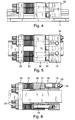
- FIGS. 4 to 6 can be pressurized via a pressure port 14, one or more interconnected pressure chambers 15, which are located in a U-shaped support body 16, with a pressure medium.
- two brake shoes 17 are fixedly connected, whose outer surfaces each form an inclined plane 18, so that the brake shoes 17 are wedge-shaped.
- the connection with the support body 16 can be realized in each case by pinning, screwing or gluing.
- the pressure chambers 15 are closed with pistons 19, which are supported in the pressure direction on a likewise U-shaped slide 20, which is pushed over the protruding in the guide direction of the support body 16 brake shoes 17.
- the inner surfaces of the slider 20, which respectively cover the areas of the brake shoes 17, are formed according to the wedge shape of the brake shoes 17.
- the slider 20 is pressed by the forces acting on it piston forces in the guide direction against springs 21, which may consist of any spring elements, such as disc springs.
- springs 21 are supported in the guide direction on a common plate 22, via which tension rods 23 are connected to the support body 16.
- tension rods 23 instead of the tension rods 23 and a frame or side plates are conceivable.
- the tension rods 23 pass through the slides 20, which has corresponding through bores.
- the surface of the inclined plane 18 may be provided with a sliding coating to reduce the friction.
- the arrangement of rolling elements between this surface and the slider 20 is conceivable, such.
- a needle cage balls or cylindrical rollers.
Landscapes
- Engineering & Computer Science (AREA)
- General Engineering & Computer Science (AREA)
- Mechanical Engineering (AREA)
- Braking Arrangements (AREA)
- Bearings For Parts Moving Linearly (AREA)
Description
- Die Erfindung betrifft eine Linearführung mit einem längs einer Führungsschiene verfahrbaren Tragkörper und einer Bremsvorrichtung, welche auf die Führungsschiene einwirkende Bremsbacken und einen Kolben aufweist, der in einem Druckraum von einem Druckmittel verschiebbar angeordnet ist, wobei die Bremsvorrichtung außerdem eine auf den Kolben einwirkende Feder aufweist.
- Linearführungen werden unter anderem bei Werkzeugmaschinen mit Hochgeschwindigkeitsantrieben, Lineartischen und Laserbearbeitungsmaschinen beispielsweise mit Lineardirektantrieben verwendet. Aus dem DE-GM 295 05 080 ist eine solche Linearführung bekannt, bei der die Brems- oder Klemmkraft von dem Druckmittel, z. B. einem hydraulischen Druckmittel wie Öl, aufgebracht wird. Aus sicherheitstechnischen Aspekten ist diese Linearführung jedoch ungeeignet, denn wenn in dem Druckmittel ein ungewollter Druckabbau eintritt, kann ein Bremsen oder Festklemmen des Tragkörpers an der Führungsschiene nicht mehr erfolgen.
- Der Erfindung liegt die Aufgabe zugrunde, eine Linearführung zu schaffen, deren Tragkörper in Notsituationen wie Druckmittelausfall in sicherer Weise an der Führungsschiene mechanisch abgebremst und verklemmt werden kann.
- Diese Aufgabe wird erfindungsgemäß dadurch gelöst, daß in dem Tragkörper neben dem Kolben in Längsrichtung der Führungsschiene ein Druckstück angeordnet ist, welches in dem von dem Druckmittel nicht beaufschlagten Zustand des Kolbens von der Feder an eine der Bremsbacken gedrückt ist, die an der Führungsschiene anliegen. Es können auch mehrere Druckstücke verwendet werden. Beispielsweise kann in dem Tragkörper in Längsrichtung der Führungsschiene beidseitig neben dem Kolben jeweils ein von der Feder beaufschlagtes Druckstück angeordnet sein. In dem Bereich des Druckraumes, in welchem sich die der Bremsbacke zugewandte Stirnfläche des Kolbens befindet, kann eine Leitung für das Druckmittel einmünden.
- Auf diese Weise erhält man eine Linearführung mit einer mechanischen Notbremse. Insbesondere für senkrechte Tischachsen, bei denen der mechanische Gewichtsausgleich versagt, oder für sich schnell bewegende horizontale Tischachsen, welche direkt angetrieben werden ohne ein mechanisches selbsthemmendes Bauteil, wie eine Antriebsspindel, kann bei einem Druckabfall des Druckmittels die sicherheitstechnisch notwendige Bremsfunktion gewährleistet werden. Bei Bereitstellung von Druckenergie öffnet die Bremse und bei Druckabfall schließt sie.
- Ausführungsbeispiele der Erfindung sind in der Zeichnung dargestellt und werden im folgenden näher beschrieben. Es zeigen:
- Figur 1
- eine Seitenansicht eines längs einer Führungsschiene verfahrbaren Tragkörpers einer Linearführung;
- Figur 2
- die Linearführung in einem Querschnitt gemäß Linie II-II der
Figur 1 ; - Figur 3
- die Linearführung in einem Querschnitt gemäß,Linie III-III der
Figur 1 ; - Figur 4
- eine Seitenansicht eines längs der Führungsschiene verfahrbaren weiteren Tragkörpers einer Linearführung;
- Figur 5
- eine Draufsicht auf die Linearführung gemäß
Figur 4 ; - Figur 6
- einen Längsschnitt durch die Linearführung gemäß
Figur 4 . - In dem in den
Figuren 1 bis 3 dargestellten Ausführungsbeispiel der Erfindung ist an einer Führungsschiene 1 ein Tragkörper 2 abgestützt und längs der Führungsschiene 1 verfahrbar. An den beiden Längsseiten der Führungsschiene 1 liegen Bremsbacken 3 an. Diese sind Teil einer Bremsvorrichtung, mit welcher der Tragkörper 2 an der Führungsschiene 1 festgeklemmt werden kann. Über einen Druckanschluß 4 wird ein in dem Tragkörper 2 ausgebildeter Druckraum 5 mit einem hydraulischen Druckmittel beaufschlagt. Ein in dem Druckraum 5 angeordneter Kolben 6 überträgt aufgrund des Flüssigkeitsdrucks eine Druckkraft auf eine Feder 7, die als Biegefeder ausgebildet und an dem Tragkörper 2 befestigt ist. Eine mit dem Druckanschluß 4 in Verbindung stehende Leitung 8 mündet in dem Bereich des Druckraums 5 ein, in dem der Kolben 6 eine von der Feder 7 abgewandte und auf die benachbarte Bremsbacke 3 gerichtete Stirnfläche aufweist. Wenn also durch die Leitung 8 Druckmittel in den Druckraum 5 einströmt, wird die Feder 7 von dem Kolben 6 nach außen gedrückt. - Die Bremsbacken 3, die sich zwischen der Führungsschiene 1 und dem Tragkörper 2 beidseitig befinden, können aus speziellen Brems- oder Gleitmaterialien bestehen. Zwischen der Feder 7 und der dem Kolben 5 zugewandten Bremsbacke 3 befinden sich außerdem zwei Druckstücke 9 jeweils vor und hinter dem Kolben 6 in Längsrichtung der Führungsschiene 1. Überschreitet die Kraft des Kolbens 6 infolge des Flüssigkeitsdrucks des Druckmittels im Druckraum 5 die Vorspannkraft der Feder 7, so sind die Druckstücke 9 unbelastet und können keine Kraft mehr auf die zugehörige Bremsbacke 3 ausüben. Der Tragkörper 2 ist dann nicht an der Führungsschiene 1 festgeklemmt und somit längs dieser in Führungsrichtung leicht verschieblich.
- Wenn infolge einer Notsituation der Druck im Druckraum 5 abfällt, so verschwindet auch die von dem Kolben 6 auf die Feder 7 ausgeübte Kraft. Dieses kann bewußt langsam oder auch schlagartig geschehen. Die Feder 7, die durch Schrauben 10 elastisch vorgespannt werden kann, wird nun nicht mehr an dem Kolben 6 abgestützt, sondern sie biegt sich in die vorgespannte Ausgangslage zurück, bis sie voll an den Druckstücken 9 anliegt. Damit übt die Feder 7 eine Federkraft über die Druckstücke 9 auf die benachbarte Bremsbacke 3 aus, die sich wiederum an der Führungsschiene 1 abstützt. Da die Feder 7 an dem Tragkörper 2 befestigt ist, zieht die Reaktionskraft der Feder 7 nun auch den Tragkörper 2 über die weitere Bremsbacke 3, die an der anderen Längsseite der Führungsschiene 1 anliegt, ebenfalls an die Führungsschiene. Dieses setzt voraus, daß ein Mitnehmer 11 des Tragkörpers 2 für eine Anschlußkonstruktion in Querrichtung zu der Führungsschiene 1 frei verschieblich gelagert ist. In Führungsrichtung ist der Mitnehmer 11 mit dem Tragkörper 2 starr verbunden. Zu diesem Zweck kann beispielsweise eine an dem Tragkörper 2 jeweils stirnseitig angebrachte Platte 12 eine Nut 13 aufweisen, in welche ein Führungsvorsprung des Mitnehmers 11 hineinragt. Die Nut 13 und der Vorsprung verlaufen quer zur Längsrichtung der Führungsschiene 1.
- Aufgrund der Vorspannung der als Biegefeder ausgebildeten Feder 7 üben die beiden Bremsbacken 3 an jeder Längsseite der Führungsschiene 1 eine zur Mitte der Führungsschiene 1 hin gerichtete Kraft aus, so daß der Tragkörper 2 an der Führungsschiene 1 festgeklemmt wird. Die Höhe dieser Bremskraft richtet sich nach der Größe der Vorspannung der Feder 7 und der Reibungskraft, die zwischen den Bremsbacken 3 und der Führungsschiene 1 auftritt. Die Vorspannung der Feder 7 läßt sich mit den Schrauben 10, die sich an den Druckstücken 9 abstützen, einstellen.
- Es sind auch Konstruktionen denkbar, bei denen je eine Feder 7 und ein oder mehrere Kolben 6 sowie Druckstücke 9 an jeder Längsseite der Führungsschiene 1 und der entsprechenden Seite des Tragkörpers 2 angeordnet sind. Bei einer solchen Konstruktion braucht der Mitnehmer 11 nicht quer zur Führungsrichtung verschiebbar zu sein. Es ist auch ein Mitnehmer denkbar, der mit dem Tragkörper 2 starr verbunden ist.
- Bei dem Ausführungsbeispiel der Erfindung nach den
Figuren 4 bis 6 können über einen Druckanschluß 14 eine oder mehrere miteinander verbundene Druckkammern 15, die sich in einem U-förmigen Tragkörper 16 befinden, mit einem Druckmittel beaufschlagt werden. Mit dem Tragkörper 16 sind zwei Bremsbacken 17 fest verbunden, deren äußere Oberflächen jeweils eine schiefe Ebene 18 bilden, so daß die Bremsbacken 17 keilförmig sind. Die Verbindung mit dem Tragkörper 16 kann jeweils durch Verstiften, Verschrauben oder Kleben realisiert werden. Die Druckkammern 15 sind mit Kolben 19 verschlossen, welche sich in Druckrichtung an einem ebenfalls U-förmigen Schieber 20 abstützen, der über die in Führungsrichtung aus dem Tragkörper 16 herausragenden Bremsbacken 17 geschoben wird. Die Innenflächen des Schiebers 20, welche jeweils die Bereiche der Bremsbacken 17 überdecken, sind entsprechend der Keilform der Bremsbacken 17 ausgebildet. Der Schieber 20 wird durch die auf ihn einwirkenden Kolbenkräfte in Führungsrichtung gegen Federn 21 gedrückt, welche aus beliebigen Federelementen, beispielsweise Tellerfedern bestehen können. Jede Feder 21 stützt sich in Führungsrichtung an einer gemeinsamen Platte 22 ab, über welche Zugstäbe 23 mit dem Tragkörper 16 verbunden sind. Statt der Zugstäbe 23 sind auch ein Rahmen oder seitliche Platten denkbar. In dem dargestellten Fall gehen die Zugstäbe 23 durch die Schieber 20 hindurch, der über entsprechende Durchgangsbohrungen verfügt. Durch die Druckkraft wird der Schieber 20 gegen die vorgespannten Federn 21 gedrückt, was zur Folge hat, daß er sich in Führungsrichtung von den schiefen Ebenen 18 der Bremsbacken 17 herunterbewegt, bis diese vollständig entlastet sind. - Beim Auslösen einer Notsituation kann der Druck des Druckmittels und damit die Kraft jedes Kolbens 19, die auf den Schieber 20 einwirkt, abfallen. Das hat zur Folge, daß der Schieber 20 nun von den Federn 21 auf die Keilflächen der Bremsbacken 17 gedrückt wird und diese aufgrund des Keilwinkels verstärkt gegen die Führungsschiene 1 drückt. Dadurch wird der Tragkörper 16 gebremst und an der Führungsschiene 1 festgeklemmt.
- Zur Erhöhung der Bremswirkung kann die Fläche der schiefen Ebene 18 mit einem Gleitbelag versehen werden, um die Reibung zu vermindern. Ebenso ist die Anordnung von Wälzkörpern zwischen dieser Fläche und dem Schieber 20 denkbar, wie z. B. ein Nadelkäfig, Kugeln oder Zylinderrollen.
-
- 1
- Führungsschiene
- 2
- Tragkörper
- 3
- Bremsbacke
- 4
- Druckanschluß
- 5
- Druckraum
- 6
- Kolben
- 7
- Feder
- 8
- Leitung
- 9
- Druckstück
- 10
- Schraube
- 11
- Mitnehmer
- 12
- Platte
- 13
- Nut
- 14
- Druckanschluß
- 15
- Druckkammer
- 16
- Tragkörper
- 17
- Bremsbacke
- 18
- schiefe Ebene
- 19
- Kolben
- 20
- Schieber
- 21
- Feder
- 22
- Platte
- 23
- Zugstab
Claims (6)
- Linearführung mit einem längs einer Führungsschiene (1) verfahrbaren Tragkörper (2) und einer Bremsvorrichtung, welche auf die Führungsschiene (1) einwirkende Bremsbacken (3) und einen Kolben (6) aufweist, der in einem Druckraum (5) des Tragkörpers (2) von einem Druckmittel verschiebbar angeordnet ist, wobei die Bremsvorrichtung außerdem eine auf den Kolben (6) einwirkende Feder(7) aufweist, dadurch gekennzeichnet, daß in dem Tragkörper (2) neben dem Kolben (6) in Längsrichtung der Führungsschiene (1) ein Druckstück (9) angeordnet ist, welches in dem von dem Druckmittel nicht beaufschlagten Zustand des Kolbens (6) von der Feder (7) an eine der Bremsbacken (3) gedrückt ist, die an der Führungsschiene (1) anliegen.
- Linearführung nach Anspruch 1, dadurch gekennzeichnet, daß in dem Tragkörper (2) in Längsrichtung der Führungsschiene (1) beidseitig neben dem Kolben (6) jeweils ein von der Feder (7) beaufschlagtes Druckstück (9) angeordnet ist.
- Linearführung nach Anspruch 1, dadurch gekennzeichnet, daß in dem Bereich des Druckraumes (5), in welchem sich die der Bremsbacke (3) zugewandte Stirnfläche des Kolbens (6) befindet, eine Leitung (8) für das Druckmittel einmündet.
- Linearführung nach Anspruch 1, dadurch gekennzeichnet, daß die auf den Kolben (6) einwirkende Feder (7) als Biegefeder ausgebildet ist.
- Linearführung mit einem längs einer Führungsschiene (1) verfahrbaren Tragkörper (16) und einer Bremsvorrichtung, welche auf die Führungsschiene (1) einwirkende Bremsbacken (17) und mindestens einen Kolben (19) aufweist, der in einer Druckkammer (15) des Tragkörpers (16) von einem Druckmittel verschiebbar angeordnet ist, wobei die Bremsvorrichtung außerdem eine auf den Kolben (19) einwirkende Feder (21) aufweist, dadurch gekennzeichnet, daß zwischen dem Kolben (19) und der Feder (21) ein Schieber (20) angeordnet ist, von welchem die mit dem Tragkörper (16) verbundenen Bremsbacken (17) im drucklosen Zustand der Druckkammer (15) gegen die Führungsschiene (1) gedrückt sind, wobei die Bremsbacken (17) für die Verstärkung der Bremswirkung keilförmig ausgebildet sind und jeweils eine Oberfläche als schiefe Ebene (18) aufweisen, an welcher der Schieber (20) mit einer entsprechend geneigten Oberfläche anliegt.
- Linearführung nach Anspruch 5, dadurch gekennzeichnet, daß die Bremsvorrichtung mehrere Federn (21) aufweist, welche an einer gemeinsamen Platte (22) abgestützt sind, die über Zugstäbe (23) mit dem Tragkörper (16) verbunden ist.
Applications Claiming Priority (3)
| Application Number | Priority Date | Filing Date | Title |
|---|---|---|---|
| DE19715014 | 1997-04-11 | ||
| DE19715014A DE19715014A1 (de) | 1997-04-11 | 1997-04-11 | Linearführung |
| PCT/EP1998/001560 WO1998046393A1 (de) | 1997-04-11 | 1998-03-18 | Linearführung |
Publications (2)
| Publication Number | Publication Date |
|---|---|
| EP0973630A1 EP0973630A1 (de) | 2000-01-26 |
| EP0973630B1 true EP0973630B1 (de) | 2008-04-09 |
Family
ID=7826131
Family Applications (1)
| Application Number | Title | Priority Date | Filing Date |
|---|---|---|---|
| EP98916990A Expired - Lifetime EP0973630B1 (de) | 1997-04-11 | 1998-03-18 | Linearführung |
Country Status (5)
| Country | Link |
|---|---|
| US (1) | US6227336B1 (de) |
| EP (1) | EP0973630B1 (de) |
| DE (3) | DE19715014A1 (de) |
| ES (1) | ES2304058T3 (de) |
| WO (1) | WO1998046393A1 (de) |
Cited By (1)
| Publication number | Priority date | Publication date | Assignee | Title |
|---|---|---|---|---|
| DE102010021859A1 (de) * | 2010-05-28 | 2011-12-01 | Schunk Gmbh & Co. Kg Spann- Und Greiftechnik | Brems- und/oder Feststellvorrichtung eines auf einer Schiene verfahrbaren Schlittens |
Families Citing this family (27)
| Publication number | Priority date | Publication date | Assignee | Title |
|---|---|---|---|---|
| DE29910187U1 (de) | 1999-06-11 | 1999-09-23 | Schaeffler Waelzlager Ohg | Bremsvorrichtung für eine Linearführung |
| JP2001227537A (ja) * | 2000-02-18 | 2001-08-24 | Nsk Ltd | 直動案内装置 |
| US6460678B1 (en) * | 2000-10-24 | 2002-10-08 | Nexen Group, Inc. | Linear motion brake |
| US6578677B2 (en) * | 2001-11-21 | 2003-06-17 | Industrial Technology Research Institute | Braking device of linear guide |
| DE10207697A1 (de) * | 2002-02-22 | 2003-09-04 | Ina Schaeffler Kg | Linearantrieb |
| US6736564B2 (en) * | 2002-09-05 | 2004-05-18 | Giddings & Lewis Machine Tools | Profiled way clamping mechanism |
| JP2004232783A (ja) * | 2003-01-31 | 2004-08-19 | Toshiba Mach Co Ltd | 直線案内装置 |
| US7181987B2 (en) * | 2003-05-02 | 2007-02-27 | Peter Winston Hamady | Precessional device and method |
| US7124861B2 (en) | 2004-02-20 | 2006-10-24 | Nexen Group, Inc. | Motion control apparatus |
| DE502005002106D1 (de) * | 2004-03-11 | 2008-01-10 | Trumpf Sachsen Gmbh | Trägeranordnung für ein maschinenportal sowie verfahren zur herstellung einer derartigen trägeranordnung |
| JP4587103B2 (ja) * | 2005-04-19 | 2010-11-24 | Smc株式会社 | シリンダ装置のガイド機構 |
| US7607519B1 (en) * | 2005-08-31 | 2009-10-27 | Douglas Keegan | Hand controlled stopping device for a camera dolly |
| ATE525164T1 (de) * | 2006-10-27 | 2011-10-15 | Nexen Group Inc | Bewegungssteuerungsvorrichtung |
| DE102008006057A1 (de) | 2008-01-25 | 2009-07-30 | Schaeffler Kg | Linearführung mit einer Brems- und/oder Klemmvorrichtung |
| DE102008031103A1 (de) | 2008-07-01 | 2010-01-07 | Schaeffler Kg | Linearführung |
| WO2010028145A1 (en) * | 2008-09-04 | 2010-03-11 | Phd, Inc. | Gripper with self-compensating jaw guides |
| DE102009012626B4 (de) * | 2009-03-11 | 2017-04-20 | Schaeffler Technologies AG & Co. KG | Linearführung mit Bremseinrichtung |
| DE202009002076U1 (de) * | 2009-04-17 | 2009-06-25 | Rk Rose + Krieger Gmbh Verbindungs- Und Positioniersysteme | Linearachse |
| JP5567459B2 (ja) * | 2010-10-07 | 2014-08-06 | ヤマハ発動機株式会社 | リニアモータ型搬送装置の連結構造 |
| RU2451614C1 (ru) * | 2011-01-17 | 2012-05-27 | Владимир Александрович Парамошко | Способ спасения пассажиров при опасности аварий скоростного железнодорожного поезда |
| TWI438052B (zh) * | 2011-10-17 | 2014-05-21 | Ind Tech Res Inst | 煞車裝置 |
| DE102014207930A1 (de) * | 2014-04-28 | 2015-10-29 | Aktiebolaget Skf | Profilgleiter, Hubsäule und Verfahren zum Montieren einer Hubsäule |
| DE102016101977A1 (de) * | 2016-02-04 | 2017-08-10 | CAE Engineering und Service GmbH | Linearantriebsystem und Bremseinrichtung für ein Linearantriebsystem |
| RU2641992C1 (ru) * | 2016-11-08 | 2018-01-23 | Владимир Александрович Парамошко | Способ спасения пассажиров и экипажа скоростного железнодорожного поезда при возможности столкновения его с другим поездом или препятствием |
| JP7090246B2 (ja) * | 2018-10-18 | 2022-06-24 | 株式会社関ヶ原製作所 | スライダ、ステージ装置、産業機械、及びスライダの反り抑制方法 |
| CN109352352B (zh) * | 2018-11-06 | 2024-01-12 | 宜昌长机科技有限责任公司 | 一种导轨导向夹紧复合装置及使用方法 |
| CN115635355A (zh) * | 2022-10-10 | 2023-01-24 | 东莞市鑫国丰机械有限公司 | 一种龙门机床拖板间隙调节装置及方法 |
Family Cites Families (22)
| Publication number | Priority date | Publication date | Assignee | Title |
|---|---|---|---|---|
| NL292899A (de) * | 1962-05-17 | |||
| DE1625490A1 (de) * | 1963-05-16 | 1970-07-30 | Windmoeller & Hoelscher | Klemmvorrichtung zum loesbaren Festklemmen eines beweglichen Maschinenteils |
| DE1765353C2 (de) * | 1968-05-04 | 1978-05-24 | Aeg-Elotherm Gmbh, 5630 Remscheid | Klemmvorrichtung zum Feststellen einer hydraulisch, pneumatisch oder elektrisch axial beweglichen Kolbenstange, insbesondere an elektrisch abtragenden Maschinen |
| DD97843A1 (de) * | 1972-07-07 | 1973-05-21 | ||
| US4185539A (en) * | 1977-03-07 | 1980-01-29 | Andrew Stratienko | Locking device for hydraulic actuator |
| DE3707046A1 (de) * | 1987-03-05 | 1988-09-15 | Haenchen Kg Herbert | Klemmvorrichtung fuer stangen |
| DE3725731A1 (de) * | 1987-08-04 | 1989-02-16 | Hasenclever Maschf Sms | Kombiniertes fuehrungs- und klemmelement, insbesondere zur anwendung in pressen mit differenziertem kurz- und langhubantrieb |
| SE464534B (sv) * | 1987-11-11 | 1991-05-06 | Bo Granbom | Bromsanordning vid en anordning foer linjaer roerelse |
| JPH0624574Y2 (ja) * | 1988-11-09 | 1994-06-29 | 日本精工株式会社 | クランプ装置付リニアガイド装置 |
| DE69100636T2 (de) * | 1990-02-09 | 1994-05-26 | Bo Kungsoer Granbom | Bremsvorrichtung in einer gradlinigen Bewegungsvorrichtung. |
| DE4012524A1 (de) * | 1990-04-19 | 1991-10-24 | Doma Tech Pneumatische Kompone | Feststellvorrichtung fuer eine linearbewegungseinheit |
| US5137400A (en) * | 1990-07-10 | 1992-08-11 | Toshiba Kikai Kabushiki Kaisha | Spindle clamping device in machine tool |
| DE4023058C2 (de) * | 1990-07-17 | 1994-08-18 | Mannesmann Ag | Kolbenstangenloser Arbeitszylinder, insbesondere für kompressible Medien, mit einer Bremseinrichtung |
| DE4192710T1 (de) * | 1990-11-01 | 1997-07-31 | Ckd Corp | Bremsvorrichtung für Zylinder |
| US5302062A (en) | 1991-08-08 | 1994-04-12 | Toshiba Kikai Kabushiki Kaisha | Spindle clamping device for machine tool |
| JP2854447B2 (ja) * | 1991-11-25 | 1999-02-03 | 日本トムソン株式会社 | 直動転がり案内ユニット及び該ユニットに用いる防振装置 |
| SE510396C2 (sv) * | 1992-10-08 | 1999-05-17 | Ckd Corp | Kolvstångslös cylinder |
| CH688970A5 (de) * | 1994-09-22 | 1998-06-30 | Schneeberger Ag W | Hydraulisch betaetigbarer Brems-/ Klemmschlitten fuer eine Fuehrungsschiene einer Linearbewegungsfuerung . |
| JP3398238B2 (ja) * | 1994-11-17 | 2003-04-21 | 日本トムソン株式会社 | 制止装置及びこれを具備した転がり案内ユニット |
| JPH08177807A (ja) * | 1994-12-26 | 1996-07-12 | Smc Corp | 位置検出装置・ブレーキ付ロッドレスシリンダ |
| DE29505080U1 (de) * | 1995-03-24 | 1995-06-08 | G & M Zimmer Ohg | Brems- und Klemmvorrichtung für Führungen |
| DE19544534C2 (de) * | 1995-11-29 | 2000-05-04 | Rexroth Star Gmbh | Bremseinrichtung für eine Linearführungseinrichtung |
-
1997
- 1997-04-11 DE DE19715014A patent/DE19715014A1/de not_active Withdrawn
-
1998
- 1998-03-18 DE DE19880452T patent/DE19880452B4/de not_active Expired - Fee Related
- 1998-03-18 US US09/402,910 patent/US6227336B1/en not_active Expired - Fee Related
- 1998-03-18 EP EP98916990A patent/EP0973630B1/de not_active Expired - Lifetime
- 1998-03-18 DE DE59814212T patent/DE59814212D1/de not_active Expired - Lifetime
- 1998-03-18 WO PCT/EP1998/001560 patent/WO1998046393A1/de not_active Ceased
- 1998-03-18 ES ES98916990T patent/ES2304058T3/es not_active Expired - Lifetime
Cited By (3)
| Publication number | Priority date | Publication date | Assignee | Title |
|---|---|---|---|---|
| DE102010021859A1 (de) * | 2010-05-28 | 2011-12-01 | Schunk Gmbh & Co. Kg Spann- Und Greiftechnik | Brems- und/oder Feststellvorrichtung eines auf einer Schiene verfahrbaren Schlittens |
| EP2397717A1 (de) * | 2010-05-28 | 2011-12-21 | Schunk GmbH & Co. KG Spann- und Greiftechnik | Brems- und/oder Festellvorrichtung eines auf einer Schiene verfahrbaren Schlittens |
| DE102010021859B4 (de) * | 2010-05-28 | 2012-05-03 | Schunk Gmbh & Co. Kg Spann- Und Greiftechnik | Brems- und/oder Feststellvorrichtung eines auf einer Schiene verfahrbaren Schlittens |
Also Published As
| Publication number | Publication date |
|---|---|
| DE19880452D2 (de) | 2000-03-30 |
| DE19715014A1 (de) | 1998-10-15 |
| DE59814212D1 (de) | 2008-05-21 |
| DE19880452B4 (de) | 2007-03-01 |
| US6227336B1 (en) | 2001-05-08 |
| EP0973630A1 (de) | 2000-01-26 |
| WO1998046393A1 (de) | 1998-10-22 |
| ES2304058T3 (es) | 2008-09-01 |
Similar Documents
| Publication | Publication Date | Title |
|---|---|---|
| EP0973630B1 (de) | Linearführung | |
| EP0936366B1 (de) | Bremsvorrichtung für eine Linearführung | |
| DE69100636T2 (de) | Bremsvorrichtung in einer gradlinigen Bewegungsvorrichtung. | |
| DE102009008815A1 (de) | Reibgehemme mit querliegendem Käfig | |
| DE102021109365A1 (de) | Klemmschlitten für eine linearführung | |
| EP0883567B1 (de) | Bremsfangvorrichtung und bremsbacke, insbesondere für aufzugskabinen | |
| DE3436075C1 (de) | Vorrichtung zur Ioesbaren Verbindung von Greiferschienenteilen der Greiferschienen in einer Transfer-Presse | |
| EP2813722B1 (de) | Mit in der Kolbenstange integriertem Käfig ausgestattete Brems- und/oder Klemmvorrichtung eines an mindestens einer Schiene geführten Schlittens | |
| EP2813723B1 (de) | Mit schräg angeordneter Abrollzone ausgestattete Brems- und/oder Klemmvorrichtung eines an mindestens einer Schiene geführten Schlittens | |
| DE102012107611A1 (de) | Hubvorrichtung mit Kniehebelgetriebe | |
| DE202009012485U1 (de) | Linearachse | |
| DE102005016719B4 (de) | Brems- und Klemmvorrichtung mit bereichsweise keilförmigen Reibbacken | |
| DE102010021859B4 (de) | Brems- und/oder Feststellvorrichtung eines auf einer Schiene verfahrbaren Schlittens | |
| DE69906199T2 (de) | Kolben-Zylinder-Stellglied für einen Schlittentisch | |
| DE29910187U1 (de) | Bremsvorrichtung für eine Linearführung | |
| DE29713607U1 (de) | Doppelwirkender Stellzylinder | |
| DE10232772B3 (de) | Druckverteilungsring für eine Längsteilanlage | |
| DE102013011657B4 (de) | Scheibenbremse für ein Nutzfahrzeug | |
| EP0996525B1 (de) | Bremsvorrichtung für eine linearführung | |
| DE3810183A1 (de) | Vorrichtung zur verriegelung einer kolbenstange einer kolben-zylinderanordnung | |
| DE9107328U1 (de) | Mehretagenpresse | |
| AT377721B (de) | Montagevorrichtung zum verbinden von schubladen- teilen | |
| EP1782914A1 (de) | Teleskopabdeckung für Werkzeugmaschine | |
| DE4238330A1 (en) | Slide valve for polymer melts - has valve plate loaded by adjustable springs to maintain seal | |
| DD200994A1 (de) | Einrichtung zum einstellen des spindelsturzes,insbesondere an fraesmaschinen |
Legal Events
| Date | Code | Title | Description |
|---|---|---|---|
| PUAI | Public reference made under article 153(3) epc to a published international application that has entered the european phase |
Free format text: ORIGINAL CODE: 0009012 |
|
| 17P | Request for examination filed |
Effective date: 19991008 |
|
| AK | Designated contracting states |
Kind code of ref document: A1 Designated state(s): CH DE ES FR GB IT LI |
|
| RAP1 | Party data changed (applicant data changed or rights of an application transferred) |
Owner name: INA-SCHAEFFLER KG |
|
| RAP1 | Party data changed (applicant data changed or rights of an application transferred) |
Owner name: SCHAEFFLER KG |
|
| GRAP | Despatch of communication of intention to grant a patent |
Free format text: ORIGINAL CODE: EPIDOSNIGR1 |
|
| GRAS | Grant fee paid |
Free format text: ORIGINAL CODE: EPIDOSNIGR3 |
|
| GRAA | (expected) grant |
Free format text: ORIGINAL CODE: 0009210 |
|
| AK | Designated contracting states |
Kind code of ref document: B1 Designated state(s): CH DE ES FR GB IT LI |
|
| REG | Reference to a national code |
Ref country code: GB Ref legal event code: FG4D Free format text: NOT ENGLISH |
|
| REG | Reference to a national code |
Ref country code: CH Ref legal event code: EP |
|
| REF | Corresponds to: |
Ref document number: 59814212 Country of ref document: DE Date of ref document: 20080521 Kind code of ref document: P |
|
| REG | Reference to a national code |
Ref country code: ES Ref legal event code: FG2A Ref document number: 2304058 Country of ref document: ES Kind code of ref document: T3 |
|
| ET | Fr: translation filed | ||
| PLBE | No opposition filed within time limit |
Free format text: ORIGINAL CODE: 0009261 |
|
| STAA | Information on the status of an ep patent application or granted ep patent |
Free format text: STATUS: NO OPPOSITION FILED WITHIN TIME LIMIT |
|
| 26N | No opposition filed |
Effective date: 20090112 |
|
| GBPC | Gb: european patent ceased through non-payment of renewal fee |
Effective date: 20090318 |
|
| REG | Reference to a national code |
Ref country code: FR Ref legal event code: ST Effective date: 20091130 |
|
| PG25 | Lapsed in a contracting state [announced via postgrant information from national office to epo] |
Ref country code: GB Free format text: LAPSE BECAUSE OF NON-PAYMENT OF DUE FEES Effective date: 20090318 Ref country code: FR Free format text: LAPSE BECAUSE OF NON-PAYMENT OF DUE FEES Effective date: 20091123 |
|
| REG | Reference to a national code |
Ref country code: DE Ref legal event code: R081 Ref document number: 59814212 Country of ref document: DE Owner name: SCHAEFFLER TECHNOLOGIES GMBH & CO. KG, DE Free format text: FORMER OWNER: SCHAEFFLER TECHNOLOGIES GMBH & CO. KG, 91074 HERZOGENAURACH, DE Effective date: 20120828 Ref country code: DE Ref legal event code: R081 Ref document number: 59814212 Country of ref document: DE Owner name: SCHAEFFLER TECHNOLOGIES AG & CO. KG, DE Free format text: FORMER OWNER: SCHAEFFLER TECHNOLOGIES GMBH & CO. KG, 91074 HERZOGENAURACH, DE Effective date: 20120828 |
|
| REG | Reference to a national code |
Ref country code: ES Ref legal event code: PC2A Owner name: SCHAEFFLER TECHNOLOGIES AG & CO.KG Effective date: 20130617 |
|
| REG | Reference to a national code |
Ref country code: CH Ref legal event code: PFA Owner name: SCHAEFFLER TECHNOLOGIES AG AND CO. KG, DE Free format text: FORMER OWNER: SCHAEFFLER KG, DE |
|
| REG | Reference to a national code |
Ref country code: DE Ref legal event code: R081 Ref document number: 59814212 Country of ref document: DE Owner name: SCHAEFFLER TECHNOLOGIES AG & CO. KG, DE Free format text: FORMER OWNER: SCHAEFFLER TECHNOLOGIES AG & CO. KG, 91074 HERZOGENAURACH, DE Effective date: 20140218 Ref country code: DE Ref legal event code: R081 Ref document number: 59814212 Country of ref document: DE Owner name: SCHAEFFLER TECHNOLOGIES GMBH & CO. KG, DE Free format text: FORMER OWNER: SCHAEFFLER TECHNOLOGIES AG & CO. KG, 91074 HERZOGENAURACH, DE Effective date: 20140218 |
|
| PGFP | Annual fee paid to national office [announced via postgrant information from national office to epo] |
Ref country code: CH Payment date: 20140326 Year of fee payment: 17 |
|
| REG | Reference to a national code |
Ref country code: CH Ref legal event code: PFUS Owner name: SCHAEFFLER TECHNOLOGIES GMBH AND CO. KG, DE Free format text: FORMER OWNER: SCHAEFFLER TECHNOLOGIES AG AND CO. KG, DE |
|
| PGFP | Annual fee paid to national office [announced via postgrant information from national office to epo] |
Ref country code: ES Payment date: 20140423 Year of fee payment: 17 Ref country code: IT Payment date: 20140328 Year of fee payment: 17 |
|
| REG | Reference to a national code |
Ref country code: DE Ref legal event code: R081 Ref document number: 59814212 Country of ref document: DE Owner name: SCHAEFFLER TECHNOLOGIES AG & CO. KG, DE Free format text: FORMER OWNER: SCHAEFFLER TECHNOLOGIES GMBH & CO. KG, 91074 HERZOGENAURACH, DE Effective date: 20150210 |
|
| REG | Reference to a national code |
Ref country code: CH Ref legal event code: PFA Owner name: SCHAEFFLER TECHNOLOGIES AG AND CO. KG, DE Free format text: FORMER OWNER: SCHAEFFLER TECHNOLOGIES GMBH AND CO. KG, DE |
|
| REG | Reference to a national code |
Ref country code: ES Ref legal event code: PC2A Owner name: SCHAEFFLER TECHNOLOGIES AG & CO.KG Effective date: 20150512 |
|
| REG | Reference to a national code |
Ref country code: CH Ref legal event code: PL |
|
| PG25 | Lapsed in a contracting state [announced via postgrant information from national office to epo] |
Ref country code: IT Free format text: LAPSE BECAUSE OF NON-PAYMENT OF DUE FEES Effective date: 20150318 |
|
| PG25 | Lapsed in a contracting state [announced via postgrant information from national office to epo] |
Ref country code: CH Free format text: LAPSE BECAUSE OF NON-PAYMENT OF DUE FEES Effective date: 20150331 Ref country code: LI Free format text: LAPSE BECAUSE OF NON-PAYMENT OF DUE FEES Effective date: 20150331 |
|
| REG | Reference to a national code |
Ref country code: ES Ref legal event code: FD2A Effective date: 20160429 |
|
| PG25 | Lapsed in a contracting state [announced via postgrant information from national office to epo] |
Ref country code: ES Free format text: LAPSE BECAUSE OF NON-PAYMENT OF DUE FEES Effective date: 20150319 |
|
| PGFP | Annual fee paid to national office [announced via postgrant information from national office to epo] |
Ref country code: DE Payment date: 20170531 Year of fee payment: 20 |
|
| REG | Reference to a national code |
Ref country code: DE Ref legal event code: R071 Ref document number: 59814212 Country of ref document: DE |