EP0971634B1 - Apparatus for inserting a flexible membrane into an eye - Google Patents
Apparatus for inserting a flexible membrane into an eye Download PDFInfo
- Publication number
- EP0971634B1 EP0971634B1 EP97943542A EP97943542A EP0971634B1 EP 0971634 B1 EP0971634 B1 EP 0971634B1 EP 97943542 A EP97943542 A EP 97943542A EP 97943542 A EP97943542 A EP 97943542A EP 0971634 B1 EP0971634 B1 EP 0971634B1
- Authority
- EP
- European Patent Office
- Prior art keywords
- instrument
- passage
- flexible membrane
- accordance
- lens
- Prior art date
- Legal status (The legal status is an assumption and is not a legal conclusion. Google has not performed a legal analysis and makes no representation as to the accuracy of the status listed.)
- Expired - Lifetime
Links
Images


Classifications
-
- A—HUMAN NECESSITIES
- A61—MEDICAL OR VETERINARY SCIENCE; HYGIENE
- A61F—FILTERS IMPLANTABLE INTO BLOOD VESSELS; PROSTHESES; DEVICES PROVIDING PATENCY TO, OR PREVENTING COLLAPSING OF, TUBULAR STRUCTURES OF THE BODY, e.g. STENTS; ORTHOPAEDIC, NURSING OR CONTRACEPTIVE DEVICES; FOMENTATION; TREATMENT OR PROTECTION OF EYES OR EARS; BANDAGES, DRESSINGS OR ABSORBENT PADS; FIRST-AID KITS
- A61F2/00—Filters implantable into blood vessels; Prostheses, i.e. artificial substitutes or replacements for parts of the body; Appliances for connecting them with the body; Devices providing patency to, or preventing collapsing of, tubular structures of the body, e.g. stents
- A61F2/02—Prostheses implantable into the body
- A61F2/14—Eye parts, e.g. lenses, corneal implants; Implanting instruments specially adapted therefor; Artificial eyes
- A61F2/16—Intraocular lenses
- A61F2/1662—Instruments for inserting intraocular lenses into the eye
- A61F2/1678—Instruments for inserting intraocular lenses into the eye with a separate cartridge or other lens setting part for storage of a lens, e.g. preloadable for shipping
-
- A—HUMAN NECESSITIES
- A61—MEDICAL OR VETERINARY SCIENCE; HYGIENE
- A61F—FILTERS IMPLANTABLE INTO BLOOD VESSELS; PROSTHESES; DEVICES PROVIDING PATENCY TO, OR PREVENTING COLLAPSING OF, TUBULAR STRUCTURES OF THE BODY, e.g. STENTS; ORTHOPAEDIC, NURSING OR CONTRACEPTIVE DEVICES; FOMENTATION; TREATMENT OR PROTECTION OF EYES OR EARS; BANDAGES, DRESSINGS OR ABSORBENT PADS; FIRST-AID KITS
- A61F2/00—Filters implantable into blood vessels; Prostheses, i.e. artificial substitutes or replacements for parts of the body; Appliances for connecting them with the body; Devices providing patency to, or preventing collapsing of, tubular structures of the body, e.g. stents
- A61F2/02—Prostheses implantable into the body
- A61F2/14—Eye parts, e.g. lenses, corneal implants; Implanting instruments specially adapted therefor; Artificial eyes
- A61F2/16—Intraocular lenses
- A61F2/1662—Instruments for inserting intraocular lenses into the eye
- A61F2/1675—Instruments for inserting intraocular lenses into the eye with a lubricated inner surface, e.g. the lubricant being coated on the inner surface or being injected through a port
Definitions
- the present invention pertains to an apparatus for inserting a flexible intraocular lens or other flexible membrane into an eye.
- the natural crystalline lens of the eye plays a primary role in focusing light onto the retina for proper vision.
- vision through the natural lens may become impaired due to an injury, or due to the formation of a cataract caused by aging or disease.
- the natural lens is typically replaced with an artificial lens.
- An artificial lens may also be implanted to make a refractive correction.
- a slender implement is inserted through a small incision in the eye to contact the natural lens.
- the implement includes a cutting tip that is ultrasonically vibrated to emulsify the lens.
- the emulsified fragments of the leas are then aspirated out of the eye through a passage provided in the cutting tip.
- the slender nature of the implement enables extraction of the lens through a small incision in the eye.
- the use of a small incision over other procedures requiring a large incision can lessen the trauma and complications experienced during the surgery and postoperatively.
- An intraocular lens commonly includes a generally disk shaped optic which focuses light on the retina and an outwardly expending haptic portion for proper positioning of the optic within the eye.
- the flexible nature of the lens enables the lens to be folded and compressed so as to occupy a smaller cross-sectional area for passage through the narrow incision and into the eye. Once inserted through the incision, the lens is permitted to expand to its original size and shape.
- U.S. Patent No. 4,681,102 to Bartell uses a hinged cartridge which closes about a lens to fold the lens into a narrower configuration. The cartridge is placed into an inserter mechanism which advances the folded lens into the eye. The inserter, however, requires several components to be manipulated and assembled during the operation.
- U.S. Patent No. 5,275,604 to Rheinish et al. pushes the lens through a narrowing lumen formed with grooves which act to fold the lens into a smaller size as it is pushed toward the eye. The manufacture of spiraling grooves in a tapering lumen is difficult if not impossible to accomplish in a practical manner.
- the resiliency of the lens causes the lens to open and resume its natural shape.
- the folding and pressing of the lens needed to pass the lens through the small incision plates a significant amount of inward pressure on the lens.
- the lens is frequently discharged from the inserted with considerable force and velocity. This forceful, uncontrolled release of the lens also places the interior of the eye at risk of being injured.
- the present invention pertains to an apparatus for inserting a flexible intraocular lens or other flexible membrane into an eye without the above-noted risks associated with inserter devices of the past.
- the apparatus is defined in claim 1. More specifically, the present inserter maintains the substantially planar orientation of the opposing side edges of the lens as the lens is laterally compressed into a smaller cross-sectional configuration for insertion through a narrow incision in the eye. Since the side edges of the lens are not folded over on themselves during compression, the lens does not swing open within the eye in order to regain its original shape. As a result, the risk of a part of the lens striking. and injuring an interior portion of the eye after release of the lens from the inserter is reduced.
- retainers in the form of troughs are formed along the interior of the inserter to receive and maintain the side edges of the lens in a substantially planar orientation during compression.
- the troughs further extend through the inserter to hold the lens during advancement toward the eye to prevent an uncontrolled rotation of the lens. In this way, the lens is assured of being discharged in its proper orientation.
- the inserter permits the lens to expand prior to its release into the eye.
- the resilient force which works to expand the compressed lens is dissipated prior to the lens being discharged from the inserter.
- the lens can thus be implanted into the eye in a controlled manner.
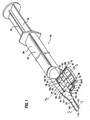
- the present invention pertains to an inserter 10 ( Figs. 1-7 ) for implanting a flexible intraocular lens or other flexible membrane into an eye.
- An intraocular lens typically includes an optic and a haptic portion, although the haptic portion is occasionally omitted.
- the haptic portion can take many forms, but is usually composed of plate or loop haptics.
- this application will describe the use of inserter 10 with a lens 12 provided with a pair of loop haptics 16a, 16b ( Figs. 1 , 5 , 6 , 8 and 10 ).
- Inserter 10 is usable with a wide variety of lenses or other flexible membranes.
- Lens 12 includes an optic 14 and a pair of loop haptics 16a, 16b ( Figs. 1 , 5 , 6 , 8 and 10 ).
- the haptics are thin, wire-like, resilient members which extend from diametrically opposed sides 18a, 18b of optic 14 in opposite directions.
- Haptics 16a, 16b are arcuate in shape such that their free ends 20 point generally back toward optic 14.
- inserter 10 includes a tubular member 22 for receiving and directing the lens into an eye ( Figs. 1-3 and 5-7 ).
- the tubular member 22 generally includes a body 24, a compressing station 26, and a cannula 28 ( Figs. 1-3 and 5 ).
- Body 24, cannula 28, and a support portion 29 of compressing station 26 are preferably formed as a unitary molded member, although an integral assembly of plural parts could also be used.
- body 24 forms a rearwardly opening passage which is adapted to receive a plunger 32 ( Fig. 1 ).
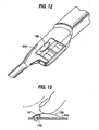
- the plunger includes a base 34 matingly received in body 24 and a shaft 36 ( Fig. 10 ) which extends forward to engage and push lens 12 into an eye.
- the base of plunger 32 is shaped to prevent rotation of the plunger relative to tubular member 22.
- the base 34 and the passage may have complementary non-circular shapes or a key and keyway construction.
- plunger 32 is preferably advanced manually through body 24, a motor or other driving arrangement could be used to move the plunger.
- Compressing station 26 includes an opening 38 in axial alignment with the passage of body 24 for receiving, compressing and directing lens 12 into cannula 28 ( Figs. 1-6D ).
- Compressing station 26 includes a support 29 molded with body 24 and cannula 28, and a compressor 40 which is mounted for movement in the support.
- Support 29 includes a generally U-shaped wing 42 provided with an elongate shelf 44 and a pair of arms 46. The arms and shelf collectively define a lateral channel or guideway 48 into which compressor 40 is moveably received.
- a lip 50 formed along the free end of each arm 46 retains compressor 40 against shelf 44 and thereby restricts the compressor to a lateral motion in channel 48.
- each lip 50 defines a shoulder 55 over which a latch 56 from compressor 40 is received to lock the compressor in place for the operation.
- An additional abutting flange (not shown) or other known construction may also be included to prevent compressor 40 from being removed from channel 48.
- Compressor 40 includes a pair of side faces 61 which are adapted to be matingly received within channel 48, and an inner sidewall 62 which is adapted to engage and compress the lens 12.
- a cover flange 64 projects beyond sidewall 62 to overlie the opposite side 58 of support 29 and enclose opening 38 when the compressor is moved inward ( Figs. 2 and 5-6D ).
- Latches 56 are positioned along each side of compressor 40 above cover flange 64. Latches 56 have ramps 65 which ease the inward movement of the compressor, and abutting faces 68 which snap out to engage shoulders 55 and lock compressor 40 in its closed position with support 29.
- the compressor is preferably irrevocably locked in place for a single use, but could be constructed to permit release if desired.
- Ledges 70 underlie lips 50 to guide the lateral movement of compressor 40 within channel 48 ( Figs. 1 and 4 ).
- Compressor 40 is laterally movable between an open position wherein cover flange 64 is spaced from side 58 of support 29 ( Fig. 1 ), and a closed position wherein cover flange 64 overlies side 58 and latches 56 engage shoulders 55 ( Figs. 2 , 5 , 6C and 6D ).
- a gap 66 is defined between cover flange 64 and side 58 for the placing of a lens 12 into opening 38 ( Fig. 1 ).
- the lens can be placed within tubular member 22 prior to shipment or by medical personnel at the time of surgery.
- sidewall 62 of compressor 40 is placed into an opposed relation with a sidewall 60 of side 58, and in axial alignment with the inner ends 52 of arms 46 ( Figs. 2 , 5 , 6C and 6D ).
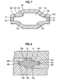
- Each sidewall 60, 62 is provided with a retainer which receives and holds the opposite side edges 18a, 18b of optic 14 to prevent the side edges from being folded over or turning when compressor 40 is moved to its closed position ( Figs. 4 and 6A-6D ). More specifically, the side edges 18a, 18b of the lens are oriented generally along a central plane. The retainers function to hold and support the side edges of the lens in this generally planar relationship during compression of the lens. Since the side edges of the lens are not folded over on themselves, the lens expands laterally within the eye without a swinging motion. This lateral shifting of the side edges for expansion of the lens is safer and less likely to contact and damage the interior of the eye than a swinging motion to unfold the lens. In the preferred construction, retainers are formed as troughs 68, 70. Nevertheless, the retainers could have other constructions so long as they maintain the sides of the lens in a substantially planar orientation and permit advancement of the lens into the eye.
- Troughs 68, 70 are preferably flanked by inclined segments 72-75 which support and compress the optic during inward movement of compressor 40, and which help maintain the sides of lens 12 in troughs 68, 70 ( Figs. 6A-6D ).
- Sidewalls 60, 62 are spaced apart by upper and lower parallel surfaces defined by cover flange 64 and shelf 44 to form an axial passage 76 through which the lens is advanced by plunger 32.
- flanking segments 72-75 can be identical mirror images to one another (see troughs 68a, 70a and segments 72a-75a of Fig. 8 ), they are preferably asymmetrical to better orient the haptics for insertion ( Fig. 6D ). More specifically, troughs 68, 70 are each partially defined by upper and lower faces 80-83. One face 80, 83 of each trough 68, 70 extends inward a greater distance than the opposing face 81, 82. The longer faces 80, 83 merge with arcuate flanking segments 72, 75. The shorter faces 81, 82 terminate and intersect flanking segments 73, 74 at points closer to the outer faces 92, 94 of troughs 68, 70. While the intersections of faces 81, 82 with flanking segments 73, 74 are preferably angular, they may also be rounded. In this particular construction, side edge 18a with leading haptic 16a is placed adjacent sidewall 60.
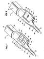
- compressing station 26b includes a support 29b molded with body 24b and cannula 28b, and a pair of opposed compressors 40b, 41b ( Figs. 9 and 10 ).
- the compressors are supported in a pair of opposite slits 96b formed in the sides of support 29b for lateral movement toward and away from each other.
- Compressors 40b, 41b have inner sidewalls 60b, 62b which are preferably shaped as described above for sidewalls 60, 62; nevertheless, the sidewalls could be symmetrically formed as with sidewalls 60a, 62a.
- An opening 66b is formed in the top of support 29b to permit the placement of a lens 12.
- a cover 101b is hinged to support 29b to overlie opening 66b before closure of compressors 40b, 41b. Latches (not shown) are provided to lock the compressors in their closed positions.
- Cannula 28 projects forwardly from the distal end of compressing station 26 to direct lens 12 into an eye ( Figs. 1-3 and 5 ).
- Cannula 28 preferably includes a proximal, funnel-shaped portion 103 which tapers to further compress the lens, and an elongate distal portion 105 which directs the compressed lens into an eye.
- the cannula could be formed to have a uniform taper across its length or provided with no taper if, for example, the compressor(s) has a longer stroke to complete the desired compression of the lens.
- Lumen 107 which extends through cannula 28, is axially aligned with passage 76 of compressing station 26 to form a continuous duct through which lens 12 is moved ( Fig. 7 ).
- Lumen 107 is preferably defined by sidewalls 109 provided with troughs 111 and upper and lower flanking segments 113, 115 to match sidewalls 60, 62 of compressing station 26.
- troughs 111 are aligned with troughs 68, 70 (when compressor 40 is in the closed position) to form a continuous retention of side edges 18a, 18b as the lens is advances into the eye.
- the sidewalls 109 of proximal portion 103 preferably converge forwardly at an angle of about 7° to further compress the lens as it is advanced through cannula 28.
- troughs 111 continue to hold the side edges 18a, 18b of optic 14 as the lens passes through cannula 28 to maintain the generally planar orientation of the side edge of the lens and to prevent turning of the lens during its advancement through lumen 107.
- Distal portion 105 of cannula 28 is an elongate, slender tube to permit entry of the inserter 10 through a narrow incision (not shown). While the sidewalls 109 in distal portion 105 are angularly oriented to the sidewalls 109 in proximal portion 103, they are identical with respect to the formation of the troughs 111 and flanking segments 113, 115. Troughs and flanking segments therefore continue through distal portion 105 to properly support and hold lens 12 throughout its passage through cannula 28. Although the sidewalls 109 in distal portion 105 preferably converge slightly for molding purposes, they could be formed with parallel walls.
- the free end 119 of cannula 28 is preferably provided with a pair of opposed longitudinal slits 121 in troughs 111 ( Figs. 1-3 , 5 and 7 ).
- Slits 121 are wide enough to permit sides 18a, 18b of optic 14 to extend outward beyond the exterior sides 123 of cannula 28. The slits therefore permit lateral expansion of the lens prior to its release into the eye.
- the natural resilient force which biases the lens to assume its original uncompressed shape is dissipated in the controlled environment of the cannula. The lens is thus not released with any velocity as in many prior art inserters.
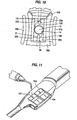
- a haptic guide 125 is optionally provided in the front of inserter 10b (or 10) to ensure the proper positioning of the leading loop haptic 16a (see Figs. 9 and 10 ).
- Haptic guide 125 includes a generally flat pull tab 127 and a slender rod 129 projecting from the pull tab.
- Rod 129 is sized to be received rearwardly within lumen 107 from free end 119.
- a hook 131 or other shoulder element is formed on the free end 133 of rod 129. In use, rod 129 is fully inserted into lumen 107 so that hook 131 is visible through the gap 66b in compressing station 26b. As the lens is loaded into the opening, leading haptic 16a is looped over hook 131.
- Pull tab 127 is manually pulled forward to remove rod 129 from inserter 10. Removal of haptic guide 125 can be performed before or after closure of compressors 40b, 41b or cover 101b. As the rod moves forward, hook 131 engages and pulls haptic 16a forward so that its free end is positioned into lumen 107. This pulling of the haptic tends to partially straighten haptic 16a to point generally in the direction of the lens' movement. This positioning of the haptic reduces the risk of the leading haptic 16a being drawn back and becoming lodged around the optic during insertion. Ribs 135 or other gripping surface are preferably formed on pull tab 127 to enhance the manual grasping of the component.
- a viscoelastic or other lubricant material is injected into the inserter to ease the movement of the lens into the eye.
- the lubricant can be injected prior to closure of compressor 40 (or cover 101b).
- cover flange 64c (or a wall of the tubular member) can be provided with an aperture 137 through which the lubricant can be injected after the closing of compressor 40c ( Fig. 11 ).
- a lubricant pouch 139 filled with a lubricant 141 can be attached to the exterior of cover flange 64d ( Figs. 12 and 13 ).
- a barb can be provided adjacent the aperture to puncture the plastic pouch to permit release of the lubricant into the passage upon the application of pressure on the pouch.
- pouch 139 includes a frangible portion (e.g., by scoring) which is aligned with a small aperture 143 in cover flange 64. Once the compressor is moved to its closed position, a user may apply pressure to lubricant pouch 139 to break open the pouch and dispense the lubricant into opening 38 through aperture 143.
- cover flange 64c can cooperate with a fixed cutter (not shown) to open pouch 139 upon the closure of compressor 40c to permit the discharge of the lubricant through aperture 143 and into the passage.
- the compressing station with or without the cannula, can be formed as a separable cartridge for compressing the lens.
- the cartridge can then be placed within an injector device for insertion of the lens into the eye after the lens has been compressed.
- flanges or other structures could be included to facilitate manipulation of the cartridge and prevent turning of the cartridge in the injector device.
- the central portion of the optic 14 could be manipulated into a U-shape, W-shape, or other folded configuration as opposed to the direct compression of the preferred embodiment So long as the side edges of the lens are maintained in a generally planar orientation the lens will still expand with a lateral shifting motion which avoids the broad swinging of the outer edges and haptics within the eye.
Applications Claiming Priority (3)
| Application Number | Priority Date | Filing Date | Title |
|---|---|---|---|
| US08/721,349 US5944725A (en) | 1996-09-26 | 1996-09-26 | Method and apparatus for inserting a flexible membrane into an eye |
| US721349 | 1996-09-26 | ||
| PCT/US1997/017128 WO1998012969A1 (en) | 1996-09-26 | 1997-09-25 | Method and apparatus for inserting a flexible membrane into an eye |
Publications (3)
| Publication Number | Publication Date |
|---|---|
| EP0971634A1 EP0971634A1 (en) | 2000-01-19 |
| EP0971634A4 EP0971634A4 (en) | 2007-10-31 |
| EP0971634B1 true EP0971634B1 (en) | 2011-10-19 |
Family
ID=24897619
Family Applications (1)
| Application Number | Title | Priority Date | Filing Date |
|---|---|---|---|
| EP97943542A Expired - Lifetime EP0971634B1 (en) | 1996-09-26 | 1997-09-25 | Apparatus for inserting a flexible membrane into an eye |
Country Status (10)
| Country | Link |
|---|---|
| US (2) | US5944725A (zh) |
| EP (1) | EP0971634B1 (zh) |
| JP (5) | JP4704522B2 (zh) |
| CN (2) | CN1602817A (zh) |
| AU (1) | AU737755B2 (zh) |
| BR (1) | BR9713477A (zh) |
| CA (1) | CA2266396C (zh) |
| ES (1) | ES2372254T3 (zh) |
| HK (1) | HK1026595A1 (zh) |
| WO (1) | WO1998012969A1 (zh) |
Families Citing this family (152)
| Publication number | Priority date | Publication date | Assignee | Title |
|---|---|---|---|---|
| US5944725A (en) * | 1996-09-26 | 1999-08-31 | Bausch & Lomb Surgical, Inc. | Method and apparatus for inserting a flexible membrane into an eye |
| US6503275B1 (en) * | 1996-11-15 | 2003-01-07 | Medevec Licensing, B.V. | Ophthalmic lens insertion instrument and package |
| US6605093B1 (en) | 1997-10-24 | 2003-08-12 | Tekia, Inc. | Device and method for use with an ophthalmologic insertor apparatus |
| AU7361898A (en) | 1997-10-24 | 1999-05-17 | Tekia, Inc. | Ophthalmologic insertor apparatus and methods of use |
| US6497708B1 (en) * | 1998-05-11 | 2002-12-24 | Medevec Licensing, B.V. | Intraocular lens insertion instrument |
| US6371960B2 (en) | 1998-05-19 | 2002-04-16 | Bausch & Lomb Surgical, Inc. | Device for inserting a flexible intraocular lens |
| US5947976A (en) * | 1998-06-02 | 1999-09-07 | Alcon Laboratories, Inc. | Asymmetric intraocular lens injection cartridge |
| US6143001A (en) * | 1998-06-02 | 2000-11-07 | Alcon Laboratories, Inc. | Asymmetric intraocular lens injection cartridge |
| US20040039401A1 (en) * | 2000-03-31 | 2004-02-26 | Chow Alan Y. | Implant instrument |
| US6283976B1 (en) * | 2000-05-05 | 2001-09-04 | Allergan Sales Inc. | Intraocular lens implanting instrument |
| US6398789B1 (en) | 2000-10-19 | 2002-06-04 | Alcon Universal, Ltd. | Intraocular lens injector cartridge |
| US6471708B2 (en) * | 2000-12-21 | 2002-10-29 | Bausch & Lomb Incorporated | Intraocular lens and additive packaging system |
| CN100488472C (zh) * | 2000-12-29 | 2009-05-20 | 视达日本有限公司 | 用于眼内插入用晶状体的插入装置 |
| US20030078657A1 (en) | 2001-01-25 | 2003-04-24 | Gholam-Reza Zadno-Azizi | Materials for use in accommodating intraocular lens system |
| US6884261B2 (en) | 2001-01-25 | 2005-04-26 | Visiogen, Inc. | Method of preparing an intraocular lens for implantation |
| US6858040B2 (en) * | 2001-01-25 | 2005-02-22 | Visiogen, Inc. | Hydraulic configuration for intraocular lens system |
| US6537283B2 (en) | 2001-08-17 | 2003-03-25 | Alcon, Inc. | Intraocular lens shipping case and injection cartridge |
| US7037312B2 (en) * | 2001-09-07 | 2006-05-02 | Canon-Staar Co., Inc. | Insertion device for deformable intraocular lens |
| US6723104B2 (en) * | 2002-03-13 | 2004-04-20 | Advanced Medical Optics, Inc. | IOL insertion apparatus and method for using same |
| WO2004014259A1 (en) * | 2002-07-26 | 2004-02-19 | Pharmacia Groningen Bv | Method and device for manipulation of an intraocular lens |
| US8623082B2 (en) | 2002-07-26 | 2014-01-07 | Amo Groningen B.V. | Method and device for manipulation of an intraocular lens |
| JP2005534365A (ja) * | 2002-07-29 | 2005-11-17 | ダックワース・アンド・ケント・リミテッド | 眼用レンズの送出 |
| US7615056B2 (en) * | 2003-02-14 | 2009-11-10 | Visiogen, Inc. | Method and device for compacting an intraocular lens |
| US20040193263A1 (en) * | 2003-03-27 | 2004-09-30 | Bryan Philip L. | IOL and assembly |
| US7476229B2 (en) * | 2003-04-07 | 2009-01-13 | Anton Meyer & Co. Ag | Cartridge for an intraocular lens |
| US7156854B2 (en) * | 2003-05-28 | 2007-01-02 | Alcon, Inc. | Lens delivery system |
| US7819880B2 (en) * | 2003-06-30 | 2010-10-26 | Depuy Products, Inc. | Implant delivery instrument |
| US7563266B2 (en) * | 2003-06-30 | 2009-07-21 | Depuy Products, Inc. | Slide and kit for delivering implants |
| US7780678B2 (en) * | 2003-08-13 | 2010-08-24 | Bausch & Lomb Incorporated | Thermal treatment to improve intraocular lens inserter lubricity |
| US7429263B2 (en) * | 2003-08-28 | 2008-09-30 | Bausch & Lomb Incorporated | Preloaded IOL injector |
| US7422604B2 (en) * | 2003-08-28 | 2008-09-09 | Bausch & Lomb Incorporated | Preloaded IOL injector |
| WO2005030097A1 (en) * | 2003-09-26 | 2005-04-07 | Bausch & Lomb Incorporated | Preloaded iol injector and method of packaging |
| US20050149056A1 (en) | 2003-12-22 | 2005-07-07 | Rathert Brian D. | IOL injector device and method |
| WO2005065592A1 (en) * | 2003-12-30 | 2005-07-21 | Bausch & Lomb Incorporated | Improved iol inserter plunger |
| US7645300B2 (en) * | 2004-02-02 | 2010-01-12 | Visiogen, Inc. | Injector for intraocular lens system |
| US7458976B2 (en) | 2005-03-02 | 2008-12-02 | Advanced Medical Optics, Inc. | Devices and methods for storing, loading, and delivering an intraocular lens |
| US8535331B2 (en) * | 2004-03-31 | 2013-09-17 | Bausch & Lomb Incorporated | IOL injector |
| US7947049B2 (en) * | 2004-03-31 | 2011-05-24 | Bausch & Lomb Incorporated | IOL injector |
| FR2875125B1 (fr) * | 2004-09-13 | 2006-12-01 | Patrick Meunier | Dispositif de chargement d'une lentille intraoculaire dans une cartouche d'injection |
| US8377123B2 (en) | 2004-11-10 | 2013-02-19 | Visiogen, Inc. | Method of implanting an intraocular lens |
| WO2006054130A1 (en) * | 2004-11-19 | 2006-05-26 | Bausch & Lomb Incorporated | Thin iol |
| US8246631B2 (en) * | 2004-11-30 | 2012-08-21 | Bausch & Lomb Incorporated | Two stage plunger for intraocular lens injector |
| US8460311B2 (en) | 2004-12-27 | 2013-06-11 | Hoya Corporation | Intraocular lens implanting device |
| US20060142780A1 (en) * | 2004-12-29 | 2006-06-29 | Joel Pynson | Preloaded IOL injector and method |
| US20060142781A1 (en) * | 2004-12-29 | 2006-06-29 | Joel Pynson | Preloaded IOL injector and method |
| ATE514395T1 (de) * | 2004-12-29 | 2011-07-15 | Bausch & Lomb | Methode zur vorbereitung eines vorbeladenen intraokularlinseninjektors |
| JP5221949B2 (ja) | 2005-01-26 | 2013-06-26 | Hoya株式会社 | 眼内レンズ挿入用器具 |
| US8435289B2 (en) | 2005-02-11 | 2013-05-07 | Abbott Medical Optics Inc. | Rapid exchange IOL insertion apparatus and methods of using |
| US8562674B2 (en) * | 2005-02-11 | 2013-10-22 | Abbott Medical Optics Inc. | Front loading IOL insertion apparatus and method of using |
| JP4836046B2 (ja) * | 2005-02-24 | 2011-12-14 | Hoya株式会社 | 眼内レンズ挿入器具 |
| JP2006333981A (ja) * | 2005-05-31 | 2006-12-14 | Canon Star Kk | 眼内挿入用レンズの挿入器具 |
| US20070005135A1 (en) * | 2005-07-01 | 2007-01-04 | Harish Makker | Intraocular lens insertion plunger with low stimulus soft tip |
| US8088161B2 (en) * | 2005-07-28 | 2012-01-03 | Visioncare Ophthalmic Technologies Inc. | Compressed haptics |
| US20070052923A1 (en) * | 2005-09-06 | 2007-03-08 | Madhu Ayyagari | Method for limiting transfer of material between two adjacent polymeric articles |
| US8574239B2 (en) | 2005-09-28 | 2013-11-05 | Hoya Corporation | Intraocular lens insertion device |
| JP4877643B2 (ja) | 2005-12-08 | 2012-02-15 | Hoya株式会社 | 眼内レンズ挿入用器具 |
| US8475526B2 (en) * | 2005-12-22 | 2013-07-02 | Bausch & Lomb Incorporated | Apparatus and methods for loading of an IOL injector |
| JP4699216B2 (ja) * | 2006-01-11 | 2011-06-08 | 株式会社ニデック | 眼内レンズ挿入システム |
| WO2007087641A2 (en) * | 2006-01-26 | 2007-08-02 | Advanced Medical Optics, Inc. | Intraocular lens insertion apparatus and lens case |
| JP4725852B2 (ja) * | 2006-06-08 | 2011-07-13 | イイファス株式会社 | 取り外し防止具 |
| JP4927473B2 (ja) * | 2006-08-11 | 2012-05-09 | 興和株式会社 | 眼内レンズの挿入器具 |
| JP4908977B2 (ja) * | 2006-09-05 | 2012-04-04 | 興和株式会社 | 眼内レンズの挿入器具 |
| US8435288B2 (en) * | 2006-09-22 | 2013-05-07 | Lenstec Barbados Inc. | System and method for storing, shipping and injecting ocular devices |
| US9149619B2 (en) | 2006-09-22 | 2015-10-06 | Lenstec Barbados Inc. | System and method for storing, shipping and injecting ocular devices |
| US9681947B2 (en) * | 2006-10-23 | 2017-06-20 | Novartis Ag | Intraocular lens delivery system with temperature control |
| US8900249B2 (en) * | 2006-10-23 | 2014-12-02 | Novartis Ag | Method of delivering temperature controlled intraocular lens |
| US8403984B2 (en) | 2006-11-29 | 2013-03-26 | Visiogen, Inc. | Apparatus and methods for compacting an intraocular lens |
| US20080147082A1 (en) * | 2006-12-13 | 2008-06-19 | Joel Pynson | Injector apparatus for use with intraocular lenses and methods of use |
| US7879090B2 (en) * | 2006-12-13 | 2011-02-01 | Bausch & Lomb Incorporated | Intraocular lens injector apparatus and methods of use |
| US20080154361A1 (en) * | 2006-12-22 | 2008-06-26 | Joel Pynson | Intraocular lens injector subassembly |
| EP2764846A1 (en) * | 2007-02-08 | 2014-08-13 | Kaneka Corporation | Injector for eye |
| US20080255577A1 (en) * | 2007-04-11 | 2008-10-16 | Downer David A | Lens Delivery System Cartridge and Method of Manufacture |
| US8747465B2 (en) | 2007-05-30 | 2014-06-10 | Hoya Corporation | Intraocular lens insertion device |
| WO2008149794A1 (ja) | 2007-05-30 | 2008-12-11 | Hoya Corporation | 眼内レンズ挿入器具 |
| JP5205376B2 (ja) * | 2007-06-05 | 2013-06-05 | スター・ジャパン株式会社 | 眼内挿入用レンズの挿入器具及び眼内挿入用レンズ内装型挿入器具 |
| JP5161211B2 (ja) * | 2007-06-06 | 2013-03-13 | スター・ジャパン株式会社 | 眼内挿入用レンズの挿入器具及び眼内挿入用レンズ内装型挿入器具 |
| US20090005788A1 (en) * | 2007-06-26 | 2009-01-01 | Rathert Brian D | Intraocular Lens Injector |
| US20090228101A1 (en) | 2007-07-05 | 2009-09-10 | Visiogen, Inc. | Intraocular lens with post-implantation adjustment capabilities |
| JP5086713B2 (ja) | 2007-07-11 | 2012-11-28 | Hoya株式会社 | 眼内レンズ挿入器具 |
| US8668734B2 (en) | 2010-07-09 | 2014-03-11 | Powervision, Inc. | Intraocular lens delivery devices and methods of use |
| US8968396B2 (en) | 2007-07-23 | 2015-03-03 | Powervision, Inc. | Intraocular lens delivery systems and methods of use |
| EP2647353B1 (en) | 2007-07-23 | 2014-12-31 | PowerVision, Inc. | Lens delivery system |
| US8382785B2 (en) * | 2007-09-27 | 2013-02-26 | Swan Valley Medical Incorporated | Apparatus and method for performing cystotomy procedures |
| JP5189356B2 (ja) * | 2007-12-28 | 2013-04-24 | 興和株式会社 | 眼内レンズの挿入器具 |
| BRPI0907725B8 (pt) * | 2008-02-07 | 2023-04-04 | Alcon Inc | cartucho de sistema de distribuição de lente |
| US8425595B2 (en) | 2008-03-12 | 2013-04-23 | Visiogen, Inc. | Method for inserting an intraocular lens |
| US8702794B2 (en) * | 2008-04-28 | 2014-04-22 | Abbott Medical Optics Inc. | Back loaded IOL insertion cartridge |
| JP5254669B2 (ja) | 2008-06-05 | 2013-08-07 | Hoya株式会社 | 眼内レンズ挿入器具及びカートリッジ |
| JP5470753B2 (ja) | 2008-06-17 | 2014-04-16 | Hoya株式会社 | 眼内レンズ挿入器具 |
| US8273122B2 (en) | 2008-06-23 | 2012-09-25 | Abbott Medical Optics Inc. | Pre-loaded IOL insertion system |
| US8961601B2 (en) * | 2008-07-09 | 2015-02-24 | Bausch & Lomb Incorporated | IOL injector comprising a moveable side wall |
| JP5323420B2 (ja) | 2008-08-21 | 2013-10-23 | Hoya株式会社 | 眼内レンズ挿入器具 |
| JP5416379B2 (ja) | 2008-09-04 | 2014-02-12 | Hoya株式会社 | 眼内レンズ挿入器具 |
| US20100087832A1 (en) * | 2008-10-03 | 2010-04-08 | Seyboth William J | Intraocular lens injector |
| US8808308B2 (en) | 2008-10-13 | 2014-08-19 | Alcon Research, Ltd. | Automated intraocular lens injector device |
| US8801780B2 (en) | 2008-10-13 | 2014-08-12 | Alcon Research, Ltd. | Plunger tip coupling device for intraocular lens injector |
| US8308736B2 (en) * | 2008-10-13 | 2012-11-13 | Alcon Research, Ltd. | Automated intraocular lens injector device |
| US20100125278A1 (en) * | 2008-11-19 | 2010-05-20 | Wagner Christopher E | Hard and Soft Tip Intraocular Lens Injector System and Method |
| US9125737B2 (en) * | 2008-12-18 | 2015-09-08 | Alcon Research, Ltd. | Constant force intraocular lens injector |
| EP2386272B1 (en) | 2009-01-07 | 2024-03-20 | Hoya Corporation | Intraocular lens insertion device |
| US9421092B2 (en) * | 2009-02-11 | 2016-08-23 | Alcon Research, Ltd. | Automated intraocular lens injector device |
| ES2549727T3 (es) * | 2009-10-22 | 2015-11-02 | Kowa Company Ltd. | Dispositivo de inserción de lentes intraoculares |
| US20110152872A1 (en) | 2009-12-23 | 2011-06-23 | Seyboth William J | Intraocular lens injector including a shaped spring |
| JP5735531B2 (ja) | 2010-04-08 | 2015-06-17 | Hoya株式会社 | 眼内移植片挿入器具 |
| US8308799B2 (en) | 2010-04-20 | 2012-11-13 | Alcon Research, Ltd. | Modular intraocular lens injector device |
| JP5511530B2 (ja) | 2010-06-10 | 2014-06-04 | Hoya株式会社 | 眼内レンズ挿入装置 |
| US9295545B2 (en) | 2012-06-05 | 2016-03-29 | James Stuart Cumming | Intraocular lens |
| US9295544B2 (en) | 2012-06-05 | 2016-03-29 | James Stuart Cumming | Intraocular lens |
| US8734512B2 (en) | 2011-05-17 | 2014-05-27 | James Stuart Cumming | Biased accommodating intraocular lens |
| US8523942B2 (en) | 2011-05-17 | 2013-09-03 | James Stuart Cumming | Variable focus intraocular lens |
| US9585745B2 (en) | 2010-06-21 | 2017-03-07 | James Stuart Cumming | Foldable intraocular lens with rigid haptics |
| US10736732B2 (en) | 2010-06-21 | 2020-08-11 | James Stuart Cumming | Intraocular lens with longitudinally rigid plate haptic |
| US9918830B2 (en) | 2010-06-21 | 2018-03-20 | James Stuart Cumming | Foldable intraocular lens with rigid haptics |
| US9351825B2 (en) | 2013-12-30 | 2016-05-31 | James Stuart Cumming | Semi-flexible posteriorly vaulted acrylic intraocular lens for the treatment of presbyopia |
| US8579969B2 (en) | 2010-07-25 | 2013-11-12 | Alcon Research, Ltd. | Dual mode automated intraocular lens injector device |
| WO2012027516A2 (en) | 2010-08-24 | 2012-03-01 | Abbott Medical Optics Inc. | Advanced pushrod and pushrod assembly features |
| US9295546B2 (en) | 2013-09-24 | 2016-03-29 | James Stuart Cumming | Anterior capsule deflector ridge |
| JP5136966B2 (ja) * | 2011-02-04 | 2013-02-06 | Hoya株式会社 | 眼内レンズ挿入器具 |
| ES2875049T3 (es) | 2011-03-24 | 2021-11-08 | Alcon Inc | Sistemas de carga de lentes intraoculares y métodos de uso |
| DE102011101940B4 (de) * | 2011-05-18 | 2014-01-02 | Iolution Gmbh | Injektor zum Implantieren einer Intraokularlinse |
| CA2861865C (en) | 2012-01-24 | 2020-12-29 | The Regents Of The University Of Colorado, A Body Corporate | Modular intraocular lens designs and methods |
| US10080648B2 (en) | 2012-01-24 | 2018-09-25 | Clarvista Medical, Inc. | Modular intraocular lens designs, tools and methods |
| US9364316B1 (en) | 2012-01-24 | 2016-06-14 | Clarvista Medical, Inc. | Modular intraocular lens designs, tools and methods |
| US10028824B2 (en) | 2012-01-24 | 2018-07-24 | Clarvista Medical, Inc. | Modular intraocular lens designs, tools and methods |
| US8657835B2 (en) | 2012-01-27 | 2014-02-25 | Alcon Research, Ltd. | Automated intraocular lens injector device |
| US9463089B2 (en) | 2012-05-21 | 2016-10-11 | Novartis Ag | Plunger system for intraocular lens surgery |
| PL2854708T3 (pl) | 2012-06-04 | 2017-09-29 | Alcon Pharmaceuticals Ltd. | Urządzenie wprowadzające soczewkę wewnątrzgałkową i sposób wyprowadzania soczewki wewnątrzgałkowej z kasety |
| SG11201408220XA (en) | 2012-06-12 | 2015-01-29 | Altaviz Llc | Intraocular gas injector |
| FR2995204B1 (fr) * | 2012-09-07 | 2015-07-31 | Sarl M D J | Dispositif d'injection d'une lentille intraoculaire de traitement de la cataracte et ensemble de traitement de la cataracte correspondant |
| CN102973238A (zh) * | 2012-12-16 | 2013-03-20 | 天津大学 | 一种用于内窥镜装置的立体镜头 |
| EP2967842B1 (en) | 2013-03-15 | 2020-11-04 | Alcon Inc. | Method of reconfiguring an intraocular lens for delivery to a delivery device |
| EP3131500B1 (en) * | 2013-11-20 | 2020-09-16 | Medicontur Orvostechnikai KFT. | Preloaded injector with rotatable member for storing and injecting hydrophobic intra ocular lenses |
| US9615916B2 (en) | 2013-12-30 | 2017-04-11 | James Stuart Cumming | Intraocular lens |
| AU2015219461B2 (en) | 2014-02-18 | 2019-10-31 | Alcon Inc. | Modular intraocular lens designs, tools and methods |
| JP6599889B2 (ja) | 2014-04-04 | 2019-10-30 | アルコン ファーマシューティカルズ リミティド | 眼内レンズ挿入器 |
| JP7066320B2 (ja) * | 2014-07-30 | 2022-05-13 | 興和株式会社 | 眼内レンズの挿入器具 |
| WO2016122805A1 (en) | 2015-01-30 | 2016-08-04 | Clarvista Medical, Inc. | Modular intraocular lens designs |
| US10588780B2 (en) | 2015-03-04 | 2020-03-17 | Alcon Inc. | Intraocular lens injector |
| JP6646987B2 (ja) | 2015-09-16 | 2020-02-14 | Hoya株式会社 | 眼内レンズ挿入器具 |
| SG11201801775TA (en) | 2015-09-16 | 2018-04-27 | Hoya Corp | Intraocular lens injector |
| US10172706B2 (en) * | 2015-10-31 | 2019-01-08 | Novartis Ag | Intraocular lens inserter |
| CA3002085A1 (en) | 2015-11-04 | 2017-05-11 | The Regents Of The University Of Colorado, A Body Corporate | Modular intraocular lens designs, tools and methods |
| DE102015224141B3 (de) | 2015-12-03 | 2017-03-16 | Carl Zeiss Meditec Ag | Intraokularlinsen-Kassette mit Gleitmittel-Zuführkanal und Injektor mit Kassette |
| US11045309B2 (en) | 2016-05-05 | 2021-06-29 | The Regents Of The University Of Colorado | Intraocular lens designs for improved stability |
| AU2017288642B2 (en) | 2016-06-28 | 2022-05-19 | Hoya Corporation | Intraocular lens insertion tool |
| US11000367B2 (en) | 2017-01-13 | 2021-05-11 | Alcon Inc. | Intraocular lens injector |
| US10568735B2 (en) | 2017-01-13 | 2020-02-25 | Alcon Inc. | Intraocular lens injector |
| US11382736B2 (en) | 2017-06-27 | 2022-07-12 | Alcon Inc. | Injector, intraocular lens system, and related methods |
| TW202005674A (zh) * | 2018-07-10 | 2020-02-01 | 瑞士商愛爾康股份有限公司 | 用於人工晶狀體注入器之側推按鈕 |
| US11224537B2 (en) | 2018-10-19 | 2022-01-18 | Alcon Inc. | Intraocular gas injector |
| US11337797B2 (en) * | 2018-12-19 | 2022-05-24 | Alcon Inc. | Cam actuated base folding mechanism |
| US11357620B1 (en) | 2021-09-10 | 2022-06-14 | California LASIK & Eye, Inc. | Exchangeable optics and therapeutics |
Family Cites Families (40)
| Publication number | Priority date | Publication date | Assignee | Title |
|---|---|---|---|---|
| US4702244A (en) * | 1982-02-05 | 1987-10-27 | Staar Surgical Company | Surgical device for implantation of a deformable intraocular lens |
| US4573998A (en) * | 1982-02-05 | 1986-03-04 | Staar Surgical Co. | Methods for implantation of deformable intraocular lenses |
| US4600004A (en) * | 1982-09-08 | 1986-07-15 | Osvaldo Lopez | Intraocular lens holder and inserter |
| US4600003A (en) * | 1982-09-08 | 1986-07-15 | Octavio Lopez | Intraocular lens inserting tool |
| US4619256A (en) * | 1982-09-08 | 1986-10-28 | Gerald Horn | Intraocular lens inserting assembly |
| US4681102A (en) * | 1985-09-11 | 1987-07-21 | Bartell Michael T | Apparatus and method for insertion of an intra-ocular lens |
| US4715373A (en) * | 1985-09-27 | 1987-12-29 | Mazzocco Thomas R | Devices for implantation of deformable intraocular lens structures |
| US4750498A (en) * | 1986-02-21 | 1988-06-14 | Coopervision, Inc. | Method and tool for inserting an intraocular lens |
| US4836202A (en) * | 1986-11-03 | 1989-06-06 | Coopervision, Inc. | Instrument for manipulating compressible intraocular lenses |
| US4950289A (en) * | 1986-11-03 | 1990-08-21 | Coopervision, Inc. | Small incision intraocular lens with adjustable refractive power |
| US4919130A (en) * | 1986-11-07 | 1990-04-24 | Nestle S.A. | Tool for inserting compressible intraocular lenses into the eye and method |
| US4747404A (en) * | 1986-11-10 | 1988-05-31 | Kresge Eye Institute Of Wayne State University | Foldable intraocular lens inserter |
| US4731079A (en) * | 1986-11-26 | 1988-03-15 | Kingston Technologies, Inc. | Intraocular lenses |
| US4763650A (en) * | 1987-01-20 | 1988-08-16 | Hauser Stephen G | Instrument for inserting a deformable lens into the eye |
| US4834094A (en) * | 1987-10-07 | 1989-05-30 | Patton Medical Technologies, Inc. | "Canoe" apparatus for inserting intra-ocular lens into the eye |
| US4765329A (en) * | 1987-10-19 | 1988-08-23 | Cumming, Redwitz & Wilson, Inc. | Intraocular lens insertion instrument |
| US4934363A (en) * | 1987-12-15 | 1990-06-19 | Iolab Corporation | Lens insertion instrument |
| US4880000A (en) * | 1987-12-15 | 1989-11-14 | Iolab Corporation | Lens insertion instrument |
| US4822360A (en) * | 1988-03-16 | 1989-04-18 | University Of Utah | Inflatable, intraocular lens and method of implanting the lens in the capsule of an eye |
| US4836201A (en) * | 1988-03-24 | 1989-06-06 | Patton Medical Technologies, Inc. | "Envelope" apparatus for inserting intra-ocular lens into the eye |
| US4862885A (en) * | 1988-05-25 | 1989-09-05 | Cumming J Stuart | Instrument for inserting a deformable intraocular lens into the eye |
| US5098439A (en) * | 1989-04-12 | 1992-03-24 | Allergan, Inc. | Small incision intraocular lens insertion apparatus |
| US4993936A (en) * | 1989-04-17 | 1991-02-19 | Siepser Steven B | Apparatus for compressing, deforming and dehydrating expansile, hydrogel intraocular lens |
| US4957505A (en) * | 1989-11-03 | 1990-09-18 | Mcdonald Henry H | Cannulated spring forceps for intra-ocular lens implantation method |
| US5123905A (en) * | 1991-06-07 | 1992-06-23 | Kelman Charles D | Intraocular lens injector |
| US5190552A (en) * | 1992-02-04 | 1993-03-02 | Kelman Charles D | Slotted tube injector for an intraocular lens |
| US5304182A (en) * | 1992-09-23 | 1994-04-19 | Kabi Pharmacia Ophthalmics, Inc. | Apparatus and method for curling and inserting flexible intraocular lenses |
| US5499987A (en) * | 1992-09-30 | 1996-03-19 | Staar Surgical Company | Deformable intraocular lens cartridge |
| PT723429E (pt) * | 1992-09-30 | 2002-09-30 | Vladimir Feingold | Sistema de insercao de lentes intra-oculares |
| US5275604A (en) * | 1992-12-03 | 1994-01-04 | Kabi Pharmacia Ophthalmics, Inc. | Contoured duct apparatus and method for insertion of flexible intraocular lens |
| US5653715A (en) * | 1993-03-09 | 1997-08-05 | Chiron Vision Corporation | Apparatus for preparing an intraocular lens for insertion |
| US5549614A (en) * | 1993-03-18 | 1996-08-27 | Tunis; Scott W. | Apparatus for folding flexible intraocular lenses |
| US5292324A (en) * | 1993-03-18 | 1994-03-08 | Henry H. McDonald | Endwise adjustable forceps for lens implantation in eye |
| US5425734A (en) * | 1993-07-02 | 1995-06-20 | Iovision, Inc. | Intraocular lens injector |
| JP3459664B2 (ja) * | 1993-07-15 | 2003-10-20 | キヤノンスター株式会社 | 変形可能な眼内レンズの挿入器具 |
| WO1995013766A1 (en) * | 1993-11-18 | 1995-05-26 | Allergan, Inc. | Deformable lens insertion apparatus |
| US5582613A (en) * | 1993-11-18 | 1996-12-10 | Allergan | Apparatus and methods for controlled insertion of intraocular lenses |
| US5578042A (en) * | 1994-03-14 | 1996-11-26 | Cumming; J. Stuart | Ophthalmic kit and method for lens insertion |
| US5776138A (en) * | 1996-01-26 | 1998-07-07 | Allergan | Apparatus and methods for IOL insertion |
| US5944725A (en) * | 1996-09-26 | 1999-08-31 | Bausch & Lomb Surgical, Inc. | Method and apparatus for inserting a flexible membrane into an eye |
-
1996
- 1996-09-26 US US08/721,349 patent/US5944725A/en not_active Expired - Lifetime
-
1997
- 1997-09-25 JP JP51586598A patent/JP4704522B2/ja not_active Expired - Lifetime
- 1997-09-25 WO PCT/US1997/017128 patent/WO1998012969A1/en active Application Filing
- 1997-09-25 ES ES97943542T patent/ES2372254T3/es not_active Expired - Lifetime
- 1997-09-25 CN CNA2004100752033A patent/CN1602817A/zh active Pending
- 1997-09-25 CA CA002266396A patent/CA2266396C/en not_active Expired - Lifetime
- 1997-09-25 AU AU44991/97A patent/AU737755B2/en not_active Expired
- 1997-09-25 EP EP97943542A patent/EP0971634B1/en not_active Expired - Lifetime
- 1997-09-25 CN CNB971991685A patent/CN1172633C/zh not_active Expired - Lifetime
- 1997-09-25 BR BR9713477-5A patent/BR9713477A/pt not_active Application Discontinuation
-
1999
- 1999-06-16 US US09/334,183 patent/US6491697B1/en not_active Expired - Lifetime
-
2000
- 2000-07-18 HK HK00104394.4A patent/HK1026595A1/xx not_active IP Right Cessation
-
2004
- 2004-09-24 JP JP2004278579A patent/JP2005028161A/ja active Pending
-
2006
- 2006-08-09 JP JP2006217414A patent/JP2008245665A/ja active Pending
- 2006-08-09 JP JP2006217413A patent/JP4294663B2/ja not_active Expired - Lifetime
- 2006-08-16 JP JP2006221933A patent/JP2006346475A/ja active Pending
Also Published As
| Publication number | Publication date |
|---|---|
| AU4499197A (en) | 1998-04-17 |
| EP0971634A1 (en) | 2000-01-19 |
| JP4294663B2 (ja) | 2009-07-15 |
| CA2266396C (en) | 2003-04-01 |
| JP2008245665A (ja) | 2008-10-16 |
| CN1234732A (zh) | 1999-11-10 |
| WO1998012969A1 (en) | 1998-04-02 |
| CN1602817A (zh) | 2005-04-06 |
| CA2266396A1 (en) | 1998-04-02 |
| BR9713477A (pt) | 2000-04-11 |
| EP0971634A4 (en) | 2007-10-31 |
| AU737755B2 (en) | 2001-08-30 |
| JP2005028161A (ja) | 2005-02-03 |
| ES2372254T3 (es) | 2012-01-17 |
| JP2001502563A (ja) | 2001-02-27 |
| JP2006346475A (ja) | 2006-12-28 |
| US5944725A (en) | 1999-08-31 |
| HK1026595A1 (en) | 2000-12-22 |
| US6491697B1 (en) | 2002-12-10 |
| JP2008245664A (ja) | 2008-10-16 |
| CN1172633C (zh) | 2004-10-27 |
| JP4704522B2 (ja) | 2011-06-15 |
Similar Documents
| Publication | Publication Date | Title |
|---|---|---|
| EP0971634B1 (en) | Apparatus for inserting a flexible membrane into an eye | |
| WO1998012969A9 (en) | Method and apparatus for inserting a flexible membrane into an eye | |
| US6471708B2 (en) | Intraocular lens and additive packaging system | |
| US6923815B2 (en) | Intraocular lens insertion apparatus | |
| US5873879A (en) | Device for inserting a flexible intraocular lens | |
| US5876440A (en) | Methods of implantation of deformable intraocular lens | |
| US5891152A (en) | Intraocular lens insertion device | |
| US5499987A (en) | Deformable intraocular lens cartridge | |
| US6334862B1 (en) | Apparatus and methods for IOL insertion | |
| US5860986A (en) | Apparatus and method for preparing an intraocular lens for insertion | |
| US6540754B2 (en) | Apparatus and method for multiply folding and inserting an intraocular lens in an eye | |
| AU2003205030B2 (en) | Apparatus for Inserting a Flexible Membrane Into an Eye | |
| AU759298B2 (en) | Apparatus for inserting a flexible membrane into an eye | |
| MXPA99002842A (en) | Method and apparatus for inserting a flexible membrane into an eye | |
| AU2002253809A1 (en) | Intraocular lens and additive packaging system | |
| AU717897B2 (en) | Intraocular lens insertion system | |
| AU2247900A (en) | Intraocular lens insertion system |
Legal Events
| Date | Code | Title | Description |
|---|---|---|---|
| PUAI | Public reference made under article 153(3) epc to a published international application that has entered the european phase |
Free format text: ORIGINAL CODE: 0009012 |
|
| 17P | Request for examination filed |
Effective date: 19990330 |
|
| AK | Designated contracting states |
Kind code of ref document: A1 Designated state(s): CH DE ES FR GB IT LI NL SE |
|
| A4 | Supplementary search report drawn up and despatched |
Effective date: 20070927 |
|
| RIC1 | Information provided on ipc code assigned before grant |
Ipc: A61F 2/16 20060101ALI20070922BHEP Ipc: A61B 17/00 20060101AFI19980618BHEP |
|
| 17Q | First examination report despatched |
Effective date: 20090303 |
|
| GRAP | Despatch of communication of intention to grant a patent |
Free format text: ORIGINAL CODE: EPIDOSNIGR1 |
|
| RTI1 | Title (correction) |
Free format text: APPARATUS FOR INSERTING A FLEXIBLE MEMBRANE INTO AN EYE |
|
| GRAS | Grant fee paid |
Free format text: ORIGINAL CODE: EPIDOSNIGR3 |
|
| RAP1 | Party data changed (applicant data changed or rights of an application transferred) |
Owner name: BAUSCH & LOMB INCORPORATED |
|
| GRAA | (expected) grant |
Free format text: ORIGINAL CODE: 0009210 |
|
| AK | Designated contracting states |
Kind code of ref document: B1 Designated state(s): CH DE ES FR GB IT LI NL SE |
|
| REG | Reference to a national code |
Ref country code: GB Ref legal event code: FG4D |
|
| REG | Reference to a national code |
Ref country code: CH Ref legal event code: EP |
|
| REG | Reference to a national code |
Ref country code: DE Ref legal event code: R096 Ref document number: 69740315 Country of ref document: DE Effective date: 20111215 |
|
| REG | Reference to a national code |
Ref country code: ES Ref legal event code: FG2A Ref document number: 2372254 Country of ref document: ES Kind code of ref document: T3 Effective date: 20120117 |
|
| REG | Reference to a national code |
Ref country code: NL Ref legal event code: VDEP Effective date: 20111019 |
|
| PG25 | Lapsed in a contracting state [announced via postgrant information from national office to epo] |
Ref country code: NL Free format text: LAPSE BECAUSE OF FAILURE TO SUBMIT A TRANSLATION OF THE DESCRIPTION OR TO PAY THE FEE WITHIN THE PRESCRIBED TIME-LIMIT Effective date: 20111019 Ref country code: SE Free format text: LAPSE BECAUSE OF FAILURE TO SUBMIT A TRANSLATION OF THE DESCRIPTION OR TO PAY THE FEE WITHIN THE PRESCRIBED TIME-LIMIT Effective date: 20111019 |
|
| PLBE | No opposition filed within time limit |
Free format text: ORIGINAL CODE: 0009261 |
|
| STAA | Information on the status of an ep patent application or granted ep patent |
Free format text: STATUS: NO OPPOSITION FILED WITHIN TIME LIMIT |
|
| 26N | No opposition filed |
Effective date: 20120720 |
|
| REG | Reference to a national code |
Ref country code: DE Ref legal event code: R097 Ref document number: 69740315 Country of ref document: DE Effective date: 20120720 |
|
| REG | Reference to a national code |
Ref country code: CH Ref legal event code: PL |
|
| PG25 | Lapsed in a contracting state [announced via postgrant information from national office to epo] |
Ref country code: CH Free format text: LAPSE BECAUSE OF NON-PAYMENT OF DUE FEES Effective date: 20120930 Ref country code: LI Free format text: LAPSE BECAUSE OF NON-PAYMENT OF DUE FEES Effective date: 20120930 |
|
| REG | Reference to a national code |
Ref country code: FR Ref legal event code: PLFP Year of fee payment: 20 |
|
| PGFP | Annual fee paid to national office [announced via postgrant information from national office to epo] |
Ref country code: IT Payment date: 20160915 Year of fee payment: 20 Ref country code: GB Payment date: 20160830 Year of fee payment: 20 |
|
| PGFP | Annual fee paid to national office [announced via postgrant information from national office to epo] |
Ref country code: FR Payment date: 20160817 Year of fee payment: 20 |
|
| PGFP | Annual fee paid to national office [announced via postgrant information from national office to epo] |
Ref country code: ES Payment date: 20160907 Year of fee payment: 20 |
|
| PGFP | Annual fee paid to national office [announced via postgrant information from national office to epo] |
Ref country code: DE Payment date: 20160928 Year of fee payment: 20 |
|
| REG | Reference to a national code |
Ref country code: DE Ref legal event code: R071 Ref document number: 69740315 Country of ref document: DE |
|
| REG | Reference to a national code |
Ref country code: GB Ref legal event code: PE20 Expiry date: 20170924 |
|
| PG25 | Lapsed in a contracting state [announced via postgrant information from national office to epo] |
Ref country code: GB Free format text: LAPSE BECAUSE OF EXPIRATION OF PROTECTION Effective date: 20170924 |
|
| REG | Reference to a national code |
Ref country code: ES Ref legal event code: FD2A Effective date: 20180508 |
|
| PG25 | Lapsed in a contracting state [announced via postgrant information from national office to epo] |
Ref country code: ES Free format text: LAPSE BECAUSE OF EXPIRATION OF PROTECTION Effective date: 20170926 |