US11382736B2 - Injector, intraocular lens system, and related methods - Google Patents
Injector, intraocular lens system, and related methods Download PDFInfo
- Publication number
- US11382736B2 US11382736B2 US16/017,369 US201816017369A US11382736B2 US 11382736 B2 US11382736 B2 US 11382736B2 US 201816017369 A US201816017369 A US 201816017369A US 11382736 B2 US11382736 B2 US 11382736B2
- Authority
- US
- United States
- Prior art keywords
- tab
- arm
- recess
- central optic
- lens system
- Prior art date
- Legal status (The legal status is an assumption and is not a legal conclusion. Google has not performed a legal analysis and makes no representation as to the accuracy of the status listed.)
- Active, expires
Links
- 238000000034 method Methods 0.000 title claims description 12
- 230000006835 compression Effects 0.000 claims abstract description 8
- 238000007906 compression Methods 0.000 claims abstract description 8
- 238000003780 insertion Methods 0.000 claims description 4
- 230000037431 insertion Effects 0.000 claims description 4
- 210000000695 crystalline len Anatomy 0.000 description 38
- 210000003811 finger Anatomy 0.000 description 16
- NIXOWILDQLNWCW-UHFFFAOYSA-N acrylic acid group Chemical group C(C=C)(=O)O NIXOWILDQLNWCW-UHFFFAOYSA-N 0.000 description 5
- 239000000523 sample Substances 0.000 description 5
- 238000013461 design Methods 0.000 description 4
- 239000000463 material Substances 0.000 description 4
- 210000003813 thumb Anatomy 0.000 description 4
- 230000008859 change Effects 0.000 description 3
- 230000007423 decrease Effects 0.000 description 3
- 238000002347 injection Methods 0.000 description 3
- 239000007924 injection Substances 0.000 description 3
- 238000003754 machining Methods 0.000 description 3
- 238000012986 modification Methods 0.000 description 3
- 230000004048 modification Effects 0.000 description 3
- 239000000853 adhesive Substances 0.000 description 2
- 230000001070 adhesive effect Effects 0.000 description 2
- 230000008901 benefit Effects 0.000 description 2
- 210000004087 cornea Anatomy 0.000 description 2
- 230000002209 hydrophobic effect Effects 0.000 description 2
- 230000007246 mechanism Effects 0.000 description 2
- 238000000465 moulding Methods 0.000 description 2
- 210000001525 retina Anatomy 0.000 description 2
- 238000001356 surgical procedure Methods 0.000 description 2
- 208000002177 Cataract Diseases 0.000 description 1
- 239000000654 additive Substances 0.000 description 1
- 230000000996 additive effect Effects 0.000 description 1
- 239000001045 blue dye Substances 0.000 description 1
- 230000004663 cell proliferation Effects 0.000 description 1
- 230000003247 decreasing effect Effects 0.000 description 1
- 230000007812 deficiency Effects 0.000 description 1
- 230000004069 differentiation Effects 0.000 description 1
- 230000003292 diminished effect Effects 0.000 description 1
- 201000010099 disease Diseases 0.000 description 1
- 208000037265 diseases, disorders, signs and symptoms Diseases 0.000 description 1
- 230000000116 mitigating effect Effects 0.000 description 1
- 239000000178 monomer Substances 0.000 description 1
- 238000004806 packaging method and process Methods 0.000 description 1
- 238000005498 polishing Methods 0.000 description 1
- 229920001296 polysiloxane Polymers 0.000 description 1
- 238000006467 substitution reaction Methods 0.000 description 1
- VLYWMPOKSSWJAL-UHFFFAOYSA-N sulfamethoxypyridazine Chemical compound N1=NC(OC)=CC=C1NS(=O)(=O)C1=CC=C(N)C=C1 VLYWMPOKSSWJAL-UHFFFAOYSA-N 0.000 description 1
- 238000012549 training Methods 0.000 description 1
- 230000000007 visual effect Effects 0.000 description 1
Images


Classifications
-
- A—HUMAN NECESSITIES
- A61—MEDICAL OR VETERINARY SCIENCE; HYGIENE
- A61F—FILTERS IMPLANTABLE INTO BLOOD VESSELS; PROSTHESES; DEVICES PROVIDING PATENCY TO, OR PREVENTING COLLAPSING OF, TUBULAR STRUCTURES OF THE BODY, e.g. STENTS; ORTHOPAEDIC, NURSING OR CONTRACEPTIVE DEVICES; FOMENTATION; TREATMENT OR PROTECTION OF EYES OR EARS; BANDAGES, DRESSINGS OR ABSORBENT PADS; FIRST-AID KITS
- A61F2/00—Filters implantable into blood vessels; Prostheses, i.e. artificial substitutes or replacements for parts of the body; Appliances for connecting them with the body; Devices providing patency to, or preventing collapsing of, tubular structures of the body, e.g. stents
- A61F2/02—Prostheses implantable into the body
- A61F2/14—Eye parts, e.g. lenses, corneal implants; Implanting instruments specially adapted therefor; Artificial eyes
- A61F2/15—Implant having one or more holes, e.g. for nutrient transport, for facilitating handling
-
- A—HUMAN NECESSITIES
- A61—MEDICAL OR VETERINARY SCIENCE; HYGIENE
- A61F—FILTERS IMPLANTABLE INTO BLOOD VESSELS; PROSTHESES; DEVICES PROVIDING PATENCY TO, OR PREVENTING COLLAPSING OF, TUBULAR STRUCTURES OF THE BODY, e.g. STENTS; ORTHOPAEDIC, NURSING OR CONTRACEPTIVE DEVICES; FOMENTATION; TREATMENT OR PROTECTION OF EYES OR EARS; BANDAGES, DRESSINGS OR ABSORBENT PADS; FIRST-AID KITS
- A61F2/00—Filters implantable into blood vessels; Prostheses, i.e. artificial substitutes or replacements for parts of the body; Appliances for connecting them with the body; Devices providing patency to, or preventing collapsing of, tubular structures of the body, e.g. stents
- A61F2/02—Prostheses implantable into the body
- A61F2/14—Eye parts, e.g. lenses, corneal implants; Implanting instruments specially adapted therefor; Artificial eyes
- A61F2/16—Intraocular lenses
- A61F2/1662—Instruments for inserting intraocular lenses into the eye
- A61F2/1664—Instruments for inserting intraocular lenses into the eye for manual insertion during surgery, e.g. forceps-like instruments
-
- A—HUMAN NECESSITIES
- A61—MEDICAL OR VETERINARY SCIENCE; HYGIENE
- A61F—FILTERS IMPLANTABLE INTO BLOOD VESSELS; PROSTHESES; DEVICES PROVIDING PATENCY TO, OR PREVENTING COLLAPSING OF, TUBULAR STRUCTURES OF THE BODY, e.g. STENTS; ORTHOPAEDIC, NURSING OR CONTRACEPTIVE DEVICES; FOMENTATION; TREATMENT OR PROTECTION OF EYES OR EARS; BANDAGES, DRESSINGS OR ABSORBENT PADS; FIRST-AID KITS
- A61F2/00—Filters implantable into blood vessels; Prostheses, i.e. artificial substitutes or replacements for parts of the body; Appliances for connecting them with the body; Devices providing patency to, or preventing collapsing of, tubular structures of the body, e.g. stents
- A61F2/02—Prostheses implantable into the body
- A61F2/14—Eye parts, e.g. lenses, corneal implants; Implanting instruments specially adapted therefor; Artificial eyes
- A61F2/16—Intraocular lenses
- A61F2/1662—Instruments for inserting intraocular lenses into the eye
- A61F2/167—Instruments for inserting intraocular lenses into the eye with pushable plungers
-
- A—HUMAN NECESSITIES
- A61—MEDICAL OR VETERINARY SCIENCE; HYGIENE
- A61F—FILTERS IMPLANTABLE INTO BLOOD VESSELS; PROSTHESES; DEVICES PROVIDING PATENCY TO, OR PREVENTING COLLAPSING OF, TUBULAR STRUCTURES OF THE BODY, e.g. STENTS; ORTHOPAEDIC, NURSING OR CONTRACEPTIVE DEVICES; FOMENTATION; TREATMENT OR PROTECTION OF EYES OR EARS; BANDAGES, DRESSINGS OR ABSORBENT PADS; FIRST-AID KITS
- A61F2/00—Filters implantable into blood vessels; Prostheses, i.e. artificial substitutes or replacements for parts of the body; Appliances for connecting them with the body; Devices providing patency to, or preventing collapsing of, tubular structures of the body, e.g. stents
- A61F2/02—Prostheses implantable into the body
- A61F2/14—Eye parts, e.g. lenses, corneal implants; Implanting instruments specially adapted therefor; Artificial eyes
- A61F2/16—Intraocular lenses
- A61F2002/1681—Intraocular lenses having supporting structure for lens, e.g. haptics
- A61F2002/1683—Intraocular lenses having supporting structure for lens, e.g. haptics having filiform haptics
- A61F2002/1686—Securing a filiform haptic to a lens body
-
- A—HUMAN NECESSITIES
- A61—MEDICAL OR VETERINARY SCIENCE; HYGIENE
- A61F—FILTERS IMPLANTABLE INTO BLOOD VESSELS; PROSTHESES; DEVICES PROVIDING PATENCY TO, OR PREVENTING COLLAPSING OF, TUBULAR STRUCTURES OF THE BODY, e.g. STENTS; ORTHOPAEDIC, NURSING OR CONTRACEPTIVE DEVICES; FOMENTATION; TREATMENT OR PROTECTION OF EYES OR EARS; BANDAGES, DRESSINGS OR ABSORBENT PADS; FIRST-AID KITS
- A61F2/00—Filters implantable into blood vessels; Prostheses, i.e. artificial substitutes or replacements for parts of the body; Appliances for connecting them with the body; Devices providing patency to, or preventing collapsing of, tubular structures of the body, e.g. stents
- A61F2/02—Prostheses implantable into the body
- A61F2/14—Eye parts, e.g. lenses, corneal implants; Implanting instruments specially adapted therefor; Artificial eyes
- A61F2/16—Intraocular lenses
- A61F2002/1681—Intraocular lenses having supporting structure for lens, e.g. haptics
- A61F2002/16902—Separable from intraocular lens
-
- A—HUMAN NECESSITIES
- A61—MEDICAL OR VETERINARY SCIENCE; HYGIENE
- A61F—FILTERS IMPLANTABLE INTO BLOOD VESSELS; PROSTHESES; DEVICES PROVIDING PATENCY TO, OR PREVENTING COLLAPSING OF, TUBULAR STRUCTURES OF THE BODY, e.g. STENTS; ORTHOPAEDIC, NURSING OR CONTRACEPTIVE DEVICES; FOMENTATION; TREATMENT OR PROTECTION OF EYES OR EARS; BANDAGES, DRESSINGS OR ABSORBENT PADS; FIRST-AID KITS
- A61F2220/00—Fixations or connections for prostheses classified in groups A61F2/00 - A61F2/26 or A61F2/82 or A61F9/00 or A61F11/00 or subgroups thereof
- A61F2220/0025—Connections or couplings between prosthetic parts, e.g. between modular parts; Connecting elements
- A61F2220/0033—Connections or couplings between prosthetic parts, e.g. between modular parts; Connecting elements made by longitudinally pushing a protrusion into a complementary-shaped recess, e.g. held by friction fit
-
- A—HUMAN NECESSITIES
- A61—MEDICAL OR VETERINARY SCIENCE; HYGIENE
- A61F—FILTERS IMPLANTABLE INTO BLOOD VESSELS; PROSTHESES; DEVICES PROVIDING PATENCY TO, OR PREVENTING COLLAPSING OF, TUBULAR STRUCTURES OF THE BODY, e.g. STENTS; ORTHOPAEDIC, NURSING OR CONTRACEPTIVE DEVICES; FOMENTATION; TREATMENT OR PROTECTION OF EYES OR EARS; BANDAGES, DRESSINGS OR ABSORBENT PADS; FIRST-AID KITS
- A61F2240/00—Manufacturing or designing of prostheses classified in groups A61F2/00 - A61F2/26 or A61F2/82 or A61F9/00 or A61F11/00 or subgroups thereof
- A61F2240/001—Designing or manufacturing processes
-
- A—HUMAN NECESSITIES
- A61—MEDICAL OR VETERINARY SCIENCE; HYGIENE
- A61F—FILTERS IMPLANTABLE INTO BLOOD VESSELS; PROSTHESES; DEVICES PROVIDING PATENCY TO, OR PREVENTING COLLAPSING OF, TUBULAR STRUCTURES OF THE BODY, e.g. STENTS; ORTHOPAEDIC, NURSING OR CONTRACEPTIVE DEVICES; FOMENTATION; TREATMENT OR PROTECTION OF EYES OR EARS; BANDAGES, DRESSINGS OR ABSORBENT PADS; FIRST-AID KITS
- A61F2250/00—Special features of prostheses classified in groups A61F2/00 - A61F2/26 or A61F2/82 or A61F9/00 or A61F11/00 or subgroups thereof
- A61F2250/0014—Special features of prostheses classified in groups A61F2/00 - A61F2/26 or A61F2/82 or A61F9/00 or A61F11/00 or subgroups thereof having different values of a given property or geometrical feature, e.g. mechanical property or material property, at different locations within the same prosthesis
Definitions
- the present disclosure generally relates to intraocular lens (IOL) systems and related injectors. More specifically, the present disclosure relates to various embodiments of modular IOL systems and injector designs for improved injection of IOL components into an eye.
- IOL intraocular lens
- the human eye functions to provide vision by transmitting light through a clear outer portion called the cornea, and focusing the image by way of a crystalline lens onto a retina.
- the quality of the focused image depends on many factors including the size and shape of the eye, and the transparency of the cornea and the lens.
- An accepted treatment for this condition is surgical removal of the lens from the capsular bag and placement of an artificial intraocular lens (IOL) in the capsular bag.
- IOL intraocular lens
- Cataractous lenses are removed by a surgical technique called phacoemulsification.
- an opening capsulexis
- a thin phacoemulsification-cutting tip is inserted into the diseased lens and vibrated ultrasonically. The vibrating cutting tip emulsifies the lens so that the lens may be aspirated out of the capsular bag.
- the diseased lens once removed, is replaced by an IOL that is inserted into the eye using an injector, and maneuvered into the empty capsular bag.
- the IOL may become stuck in the injector, or the IOL may become damaged as a result of poor technique or training, as in the case of a damaged trailing IOL haptic. Improvements in injector design are needed to address this problem.
- Embodiments of the present disclosure provide an injector for injecting one or more components of an IOL system into the eye, the injector having a housing, a cartridge for holding the IOL system component, a distal nozzle having a tapered lumen and a plunger having a tip disposed in a channel of the housing.
- the plunger tip may have two arms that change from an expanded configuration when disposed in the proximal end of the nozzle lumen and a contracted configuration when disposed in the distal end of the nozzle lumen.
- the arms may have a gap between them that decreases as the arms pass through the nozzle.
- the arms may remain in contact with the inner wall of the nozzle lumen as the arms pass through the nozzle.
- the distal ends of the arms may be free or attached to a collapsible link, for example.
- the arms may include inwardly extending fingers that are offset relative to each other such that they bypass each other as the arms move toward each other. The fingers may be configured to prevent the IOL system component from passing through the gap between the arms.
- the distal end of the arms or the distal end of the link may include a bevel with a distal-most edge and a distal-facing surface.
- the distal-facing surface may be configured to engage and push the IOL system component.
- the distal-most edge may be in contact with the inner wall of the nozzle lumen to prevent the IOL system component from passing between the arm and the inner wall as the IOL system component passes through the nozzle.
- Embodiments of the present disclosure also provide a modular IOL system comprising a primary component, such as a base, and a secondary component, such as a lens.
- an intraocular lens system may include a base that may include an annular body, an opening extending through the annular body in an axial direction of the annular body, and a recess extending circumferentially about the opening.
- the system also may include a lens that may be insertable into and removable from the recess.
- the lens may include a central optic, a first tab protruding radially away from the central optic, and a second tab protruding radially away from the central optic.
- the second tab may be more resistant to compression in a radial direction than the first tab.
- the first tab may include a first arm protruding radially away from the central optic, a second arm protruding radially away from the central optic and extending away from the first arm, and a third arm extending from the first arm to the second arm. Movement of one or more of the first, second, and third arms may result in deformation of the first tab.
- an intraocular lens system may include a base including an annular body, an opening extending through the annular body in an axial direction of the annular body, and a recess extending circumferentially about the opening.
- the system also may include a lens configured for insertion into and removable from the recess.
- the lens may include a central optic, a first tab extending radially away from the central optic, and a second tab extending radially away from the central optic.
- the second tab may be more resistant to compression than the first tab.
- the first tab may include a first arm extending radially away from the central optic, a second arm extending radially away from the central optic, and a third arm extending between the first arm with the second arm.
- One or more of the first, second, and third arms is configured to deform to move the first tab between a compressed state and an extended state. In the extended state of the first tab, an obtuse angle may be formed between the first and second arms.
- a method for assembling an intraocular lens system may include inserting one of: (a) a first tab and (b) a second tab, of a lens of the intraocular lens system, into a recess of a base of the intraocular lens system.
- the second tab may be more resistant to compression than the first tab.
- the lens may include a central optic, the first tab extending radially away from the central optic, and the second tab extending radially from the central optic.
- the first tab may include a first arm extending radially away from the central optic, a second arm extending radially away from the central optic and away from the first arm, and a third arm linking the first and second arms.
- the base may include an annular body and an opening extending through the annular body in an axial direction of the annular body.
- the recess may extend circumferentially about the opening.
- the method also may include inserting the other of the first and second tabs into the recess.
- the other of the first and second tabs may be inserted into the recess while the at least one of the first and second tabs is in the recess.
- FIG. 1A is an exploded view of an IOL system injector according to an embodiment of the present disclosure
- FIG. 1B is an assembly view of the IOL system injector shown in FIG. 1A ;
- FIG. 2 is a side view of a plunger of the IOL system injector shown in FIGS. 1A and 1B ;
- FIG. 2A is a close-up side view of a tip of the plunger shown in FIG. 2 ;
- FIG. 2B is a close-up end view of the tip of the plunger shown in FIG. 2 ;
- FIG. 2C is a close-up perspective view of the tip of the plunger shown in FIG. 2 ;
- FIG. 3A is a close-up perspective view of an alternative plunger tip
- FIG. 3B is a close-up perspective view of another alternative plunger tip
- FIGS. 4A to 4C are schematic illustrations showing how the tip of the plunger of FIG. 2 is squeezed as the tip passes through a nozzle;
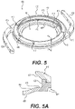
- FIG. 5 is a perspective view of a base of a modular IOL system
- FIG. 5A is a cross-sectional view taken along line A-A in FIG. 5 ;
- FIG. 6 is a top view of a lens of a modular IOL system
- FIG. 7 is a perspective view of a loading cartridge for use in the IOL system injector shown in FIGS. 1A and 1B ;
- FIG. 7A is an end view of the loading cartridge shown in FIG. 7 ;
- FIG. 7B is a cross-sectional view taken along line B-B in FIG. 7A ;
- FIG. 7C is the same cross-sectional view shown in FIG. 7B with a base positioned therein;
- FIG. 8 is a perspective view of an alternative holder for use in the IOL system injector shown in FIG. 1 ;
- FIG. 8A is a close-up perspective view of the holder shown in FIG. 8 ;
- FIG. 8B is a close-up perspective view of the holder shown in FIG. 8 with a base positioned therein.
- IOL system injectors The following detailed description describes various embodiments of IOL system injectors. Features described with reference to any one embodiment may be applied to and incorporated into other embodiments.
- IOL system injector 10 generally includes an injector housing 20 , a plunger 30 , a loading cartridge 40 , a nozzle (a.k.a. cartridge tip) 50 and a spring 60 .
- the housing 20 includes finger grips 22 , a nozzle holder 24 , a cartridge holder 26 and an internal channel 28 extending therethrough.
- the plunger 30 includes a thumb pad 32 , a proximal shaft 34 , a distal shaft 36 and a plunger tip 70 .
- the IOL system loading cartridge 40 includes a first folding wing 42 , a second folding wing 44 with a locking mechanism, and a chamber 46 configured to hold the IOL system when the wings 42 , 44 are closed.
- the nozzle 50 includes an internal lumen (not visible) that has a decreasing cross-sectional area proximal to distal.
- the nozzle 50 also includes a beveled tip 52 for insertion into the incision in the eye.
- the injector 10 is modular in nature such that the nozzle 50 may be inserted into the nozzle holder 24 of the housing 20 , the cartridge may be inserted into the cartridge holder 26 of the housing 20 , the spring 60 may be disposed on the distal shaft 36 of the plunger 30 , and the plunger 30 together with spring 60 may be inserted into the channel 28 of the housing 20 to form an assembled IOL system injector 10 as shown in FIG. 1B .
- an IOL system component may be loaded or pre-loaded in the chamber 46 of the loading cartridge 40 .
- the loading cartridge 40 is placed in the cartridge holder 26 in the housing 20 .
- the wings 42 , 44 are folded or closed to essentially roll or fold the IOL system component such that it has a reduced profile suitable for injection.
- the plunger 30 may be advanced distally through the channel 28 in the housing 20 until the tip 70 of the plunger 30 engages the IOL system component in the loading cartridge 40 .
- the plunger 30 pushes the IOL system component out of the loading cartridge 40 and into the nozzle 50 .
- the tapered lumen in the nozzle 50 further reduces the profile of the rolled IOL system component making it suitable for injection through a micro incision in the eye.
- the plunger 30 may then be advanced further until the IOL system component exits the tip 52 of the nozzle 50 and is thus delivered into the eye.
- the other components of the injector 10 may be similar to an injector sold under the trade name Accuject 2.2-HT from Medicel, Switzerland.
- the plunger 30 has a number of unique attributes.
- the features of the plunger 30 may be incorporated into other injector designs known in the art.
- the plunger 30 is shown in more detail.
- the plunger 30 includes a thumb pad 32 , a proximal shaft 34 , a distal shaft 36 and a tip 70 .
- the tip 70 is shown in more detail in FIGS. 2A, 2B and 2C .
- Plunger tip 70 includes a first (top) arm 72 and a second (bottom) arm 74 .
- the arms 72 , 74 are connected to and extend distally from the distal shaft 36 .
- the distal ends of the arms 72 , 74 may be free as shown, with no connection therebetween.
- the arms 72 , 74 are flexible and pivot about their connection to the distal shaft 36 such that they that can change from an expanded configuration when disposed in the proximal end of the lumen in the nozzle 50 and a contracted configuration when disposed in the distal end of the lumen in the nozzle.
- the arms 72 , 74 have a gap between them that decreases as the arms 72 , 74 pass through the nozzle 50 . In other words, the arms 72 , 74 are squeezed together as the tip 70 passes through the nozzle 50 .
- the outwards facing surfaces of the arms 72 , 74 remain in contact with the inner wall of the lumen in the nozzle 50 as they pass therethrough.
- Fingers 76 , 78 extend inwardly in a proximal-turning curve from the arms 72 , 74 , respectfully.
- the proximal ends of the fingers 76 , 78 may be attached to the arms 72 , 74 at a location set back from the distal-most end of the arms 72 , 74 , and the distal ends of the fingers 76 , 78 may be free, as shown.
- the fingers 76 , 78 may be laterally off-set relative to each other such that they bypass each other as the arms 72 , 74 are squeezed together.
- the profile of the arms 72 , 74 may be configured (e.g., in an end-view rectangular profile with a height greater than a width) such that the top side of the top arm 72 and the bottom side of the bottom arm 74 remain in contact with the inner wall defining the lumen in the nozzle 50 , but the lateral sides of the arms 72 , 74 do not.
- This configuration allows the arms 72 , 74 together with the fingers 76 , 78 to span across the entire lumen in the nozzle 50 in one direction to prevent the tip 70 from bypassing the IOL system component as the tip 70 is advanced through the nozzle 50 , which otherwise could lead to a stuck IOL in the nozzle 50 .
- the lateral sides of the arms 72 , 74 do not contact the inner wall defining the lumen in the nozzle 50 , space is provided therebetween for the trailing haptic of the IOL system component if the plunger tip 70 bypasses it, allowing the haptic to be released as it exits the tip 52 of the nozzle 50 , thus preventing a stuck IOL system component in the nozzle 50 .
- This configuration also reduces friction between the tip 70 and the inner wall defining the lumen in the nozzle 50 because the only the top and bottom sides of the arms 72 , 74 are in contact with the inner wall, and the lateral sides are not.
- the arms 72 , 74 may have an expanded (unconstrained) height that is greater than the inside diameter of the lumen in the nozzle 50 and greater than the outside diameter of the distal plunger shaft 36 such that they flare outwardly and distally.
- Each arm 72 , 74 may have an overall length that is at least two times greater than their expanded height.
- the height and width of each arm 72 , 74 may be at least five times less than their overall length and their height may taper along their length.
- the arms 72 , 74 may be diametrically opposed (i.e., 180 degrees apart) and their overall length may be approximately equal.
- a bevel 80 may be provided on the distal end of one or both arms 72 , 74 .
- the bevel 80 may include a distal-most edge 82 and a distal-facing surface 84 .
- the bevel 80 may slope in a proximal and inward direction, away from the inner wall of the lumen in the nozzle 50 , such that the edge 82 is in contact with the inner wall and the slope of the bevel 80 biases the IOL system component away from the inner wall. This configuration mitigates against the IOL system component becoming stuck between the tip 70 and the inner wall of the lumen in the nozzle 50 as the tip 70 is advanced through the nozzle 50 .
- the plunger tip 70 does not include fingers 76 , 78 , but rather includes link 90 extending from and between the distal ends of the arms 72 , 74 .
- Link 90 may include a hinge and/or may be formed of highly flexible material to allow it to collapse as the arms 72 , 74 are squeezed together as they are advanced through the nozzle 50 .
- the link 90 may include bevels 80 that function as described above.
- the plunger tip 70 does not include fingers 76 , 78 , but rather includes a tongue 96 extending from arm 74 into a groove defined by walls 92 , 94 extending from arm 72 .
- Other aspects of the plunger tip 70 may be the same or similar as described previously. This tongue and groove arrangement may serve the same or similar purpose as fingers 76 , 78 .
- advancement of the plunger tip 70 through the lumen in the nozzle (a.k.a. cartridge tip) 50 is schematically illustrated in step-wise fashion.
- the nozzle 50 is shown in transparent view with distal beveled tip 52 , distal opening 54 and through lumen 56 , and only a distal portion of the plunger 30 including tip 70 is shown.
- the cross-sectional area or diameter of the lumen 56 in the nozzle 50 gradually decreases from proximal to distal end.
- the arms 72 , 74 are gradually squeezed together as the tip and IOL (not shown) pass through the nozzle 50 .
- IOL not shown
- the arms 72 , 74 are in an expanded state when in a proximal portion of the nozzle 50 .
- the arms 72 , 74 are squeezed by the inner walls defining the nozzle lumen 56 and are changing to a compressed or contracted state.
- the arms 72 , 74 are in a contracted state when in a distal portion of the nozzle 50 . Note in FIG. 4A that the distal ends of the fingers 76 , 78 are bypassing each other, in FIG. 4B they are abutting the inside surface of the arms 72 , 74 , and in FIG. 4C they are bent inward.
- the arms 72 , 74 together with the fingers 76 , 78 span across the entire lumen 56 in at least one direction (but not all) to keep the IOL system component in front of the tip 70 and prevent the IOL system component from becoming stuck between the tip 70 and the inner wall of the nozzle lumen 56 .
- the lateral sides of the arms 72 , 74 and the fingers 76 , 78 are not in contact with the inner wall of the nozzle lumen 56 , thereby reducing friction.
- the injector 10 may be used with a wide variety of IOL system components including modular IOL system components and non-modular IOLs (e.g., unitary and/or monolithic IOLs).
- the injector may be used to inject a base component and an optic component that form a modular IOL system when assembled.
- the base and optic may be injected into the eye separately and assembled in the eye, or assembled outside the eye and injected into the eye together.
- a description of an example base component 400 is provided with reference to FIGS. 5 and 5A
- a description of an example optic component 500 is provided with reference to FIG. 6 . Further details regarding a similar modular IOL system configuration may be found in U.S. Non-provisional patent application Ser. No. 15/585,901, filed May 3, 2017 and entitled Intraocular Lens Designs for Improved Stability, which is incorporated herein by reference.
- the base 400 includes an annular ring 402 defining a center hole 404 .
- a pair of haptics 406 extend radially outward from the annular ring 402 .
- the annular ring 402 includes a lower rim 408 , an upper rim 410 and an inward-facing recess 412 , into which the lens 500 may be inserted to form the modular IOL system.
- the lower rim 408 may include a pair of diametrically opposed (180 degrees) folding notches 414
- the upper rim 410 may include a corresponding pair of folding notches 416 .
- Folding notches 414 , 416 may be aligned with the mid portions of the haptics 406 and are configured to provide a natural folding crease to fold the base in half in the loading cartridge 40 of the injector 10 , thereby aligning the mid portion of the haptic with the plunger tip 70 .
- Notches 414 , 416 may also provide access for a probe (e.g., Sinskey hook) intra-operatively, which allows the base 400 to be more easily manipulated.
- the haptics 406 may include holes 415 adjacent the annular ring 402 for intraoperative manipulation with a probe.
- a series of vent holes 413 may be distributed around the upper rim 410 .
- the recess 412 may have a tapered profile defined by horizontal posterior surface 418 , a vertical lateral or outer surface 422 and a flared anterior surface 426 extending radially inward and anteriorly outward from the vertical outer surface 422 .
- the inside diameter of the posterior rim 408 may be smaller than the inside diameter of the anterior rim 410 .
- the lens 500 may be placed through the circular opening 404 defined by the anterior rim 410 to land or rest upon the posterior rim 408 , and the flared anterior wall 426 together with the flared posterior wall 428 may act as a funnel to guide the tabs 504 and 506 of the lens 500 into the deep portion of the recess 412 .
- a pair of square edges 417 may extend around the posterior periphery of the annular ring 402 to help reduce cellular proliferation (posterior capsular opacification or PCO) onto the lens 500 .
- the lens 500 may include an optic portion 502 and one or more tabs 504 and 506 .
- tab 504 is fixed, whereas tab 506 may be actuated.
- tab 504 is more resistant to deformation (e.g., compression and/or expansion) in a radial direction than tab 506 .
- Fixed tab 504 may include a thru hole 508 so that a probe (e.g., Sinskey hook) or similar device may be used to engage the hole 508 and manipulate the tab 504 .
- Actuatable tab 506 may be actuated between a compressed position for delivery into the hole 404 of the base 400 , and an uncompressed extended position (shown) for deployment into the recess 412 of the base 400 , thus forming an interlocking connection between the base 400 and the lens 500 . It also is contemplated that actuatable tab 506 may be inserted into recess 412 , and may be actuated between the compressed position to facilitate entry of fixed tab 504 into recess 412 , and the uncompressed extended position to insert fixed tab 504 further into recess 412 to form the interlocking connection between base 400 and lens 500 .
- Actuatable tab 506 may include two arms 510 and 512 that extend radially outward in different (e.g., opposite) directions. In one example, an obtuse angle may be formed between the directions.
- Each arm 510 , 512 may have one end connected to the edge of the optic 502 and the other end connected to middle arm 511 .
- Hinge portions may connect ends of arms 510 and 512 to optic 502 , and may connect other ends of arms 510 and 512 to middle arm 511 .
- Each of arms 510 , 511 , and 512 may include one or more linear portions.
- middle arm 511 may include two linear portions meeting at a mid-portion of middle arm 511 .
- Middle arm 511 may be angled radially inward as shown with an apex in the mid-portion thereof.
- the apex may be a hinge portion.
- Portions of optic 502 and arms 510 , 511 , and 512 may form a ring around a aperture through actuatable tab 506 . Dimensions of that aperture may change as actuatable tab 506 moves between compressed and extended states.
- the actuatable tab 506 may bend along all three arms 510 , 511 , 512 , and/or may bend along the hinge portions, when moving between its compressed and extended states, but may provide a single portion (apex of middle arm 511 ) for initial insertion into recess 412 of base 400 .
- a rim 514 may extend around the perimeter of the optic 502 , terminating shy of the arms 510 and 512 , thus allowing the arms 510 and 512 to fully compress against the edge of the optic 502 .
- the edge of optic 502 may be planar, and may contact one or more planar surfaces of arm 510 and/or arm 512 .
- the rim 514 of the lens 500 may have an outside diameter that is greater than the inside diameter of the posterior rim 408 of the base 400 such that the lens 500 doesn't fall through the opening 404 of the base 400 and such that the lens 500 is circumferentially supported around its perimeter by the posterior rim 408 of the base 400 .
- a gusset with a guide hole 516 may be disposed between the two arms 510 and 512 to facilitate manipulation by a probe.
- a guide hole 508 may be provided in the fixed tab 504 to provide access for a probe (e.g., Sinskey hook) or similar device to manipulate the fixed tab 504 into the recess 412 in the base 400 .
- a notch 518 may be provided in the fixed tab 504 to provide asymmetry as a visual indicator that the anterior side is up (rather than down) when the notch is counter-clockwise of the hole 508 .
- the base 400 and lens 500 may be formed by cryogenically machining and polishing hydrophobic acrylic material.
- the base 400 may be manufactured by forming two (anterior and posterior) components and adhesively connecting them together.
- the two components may be cryogenically machined hydrophilic acrylic connected together by a U.V. curable adhesive.
- the two components may be formed of different materials adhesively connected together.
- the anterior component may be formed of hydrophilic acrylic which does not adhere to ocular tissue
- the posterior component may be formed of hydrophobic acrylic which does adhere to ocular tissue.
- the base 400 may be manufactured by cryogenic machining the first component and over-molding the second component.
- the first component may include geometric features that become interlocked when over-molded, thus mitigating the need for adhesive to connect the components.
- the base 400 may be manufactured by cryogenic machining of hydrophilic acrylic to form the posterior component, and over-molding the anterior component of a moldable material such as silicone.
- all or a portion of the annular ring 402 may include coloration to enhance the ability to visualize the tabs 504 , 506 relative to the recess 412 to better determine if the tabs 504 , 506 are anterior to, inside or posterior to the recess 412 .
- the annular ring 402 may be a first color and the tabs 504 , 506 may be a second (different) color.
- the annular ring 402 comprises an anterior component and a posterior component, either or both of the anterior and posterior components may be a first color and the tabs 504 , 506 may be a second (different) color.
- the annular ring 402 may be a blue color (blue dye monomer additive) and the tabs 504 , 506 may be a natural (transparent) color.
- the inside portion of the posterior rim 408 may appear light blue, and the overlap of the anterior rim 410 and posterior rim 408 may appear dark blue.
- the position of the tabs 504 , 506 relative to the recess 412 may be visually more apparent to more easily facilitate assembling the optic 500 to the base 400 .
- the optic 500 may be similarly sized to a conventional IOL and the base 400 may be slightly larger to allow the optic 500 to fit therein.
- a conventional loading cartridge may be used for both the base 400 and the optic 500 .
- the loading cartridge 40 includes a first folding wing 42 , a second folding wing 44 with a locking mechanism, and a chamber 46 configured to hold the base 400 when the wings 42 , 44 are closed.
- FIG. 7B which is a cross-sectional view taken along line B-B in FIG. 7A
- the sides of the chamber may include shoulders 48 such that a proximal width of the chamber 46 is wider than a distal width of the chamber 46 .
- the proximal width may be about 7.9 mm and the distal width may be about 6.6 mm.
- This configuration defines a tapered chamber lumen that gradually compresses the relatively larger base 400 into the proximal portion of the nozzle lumen 56 as the plunger 30 pushes the base 400 distally.
- the shoulders 48 abut the annular ring 402 of the base 400 thereby providing a backstop for the base 400 to maintain the axial (longitudinal) position of the base 400 in the loading cartridge 40 , particularly when the tip 70 of the plunger 30 engages the proximal side of the base 400 .
- the folding notches 414 of the base 400 may be aligned with the longitudinal axis of the loading cartridge 40 to provide a hinge for uniform diametric folding of the base 400 when the wings 42 , 44 of the cartridge 40 are closed.
- the base 400 and/or optic 500 may be loaded or pre-loaded in the chamber 46 of the loading cartridge 40 .
- a holder 100 may be used to hold the base 400 or optic 500 in the chamber 46 of the loading cartridge 40 while packaged and shipped as shown in FIGS. 8-8B .
- Holder 100 may include a holding plate 102 , a connector portion 104 , an arm 106 and a retaining pin 108 .
- the holding plate 102 may cover all or a portion of the base 400 or optic 500 in the chamber 46 .
- the connector portion 104 may attach to the wing 44 of the cartridge 44 , and the arm 106 may engage the other wing 42 of the cartridge 40 via one or more slots.
- the retaining pin 108 may extend from a lateral edge of the holding plate 102 at position recessed from a proximal edge of the holding plate 102 such that it is positioned between the annular ring 402 and the trailing or proximal haptic 402 of the base 400 as shown in FIG. 8B . This arrangement, when combined with the shoulders 48 of the cartridge, retain the base 400 and limit movement in all directions during packaging and shipping.
Abstract
Description
Claims (18)
Priority Applications (18)
| Application Number | Priority Date | Filing Date | Title |
|---|---|---|---|
| US16/017,369 US11382736B2 (en) | 2017-06-27 | 2018-06-25 | Injector, intraocular lens system, and related methods |
| BR122024001076-3A BR122024001076A2 (en) | 2017-06-27 | 2018-06-26 | INTRAOCULAR LENS SYSTEM |
| KR1020237002913A KR102627474B1 (en) | 2017-06-27 | 2018-06-26 | Injector, intraocular lens system, and related methods |
| CA3066888A CA3066888A1 (en) | 2017-06-27 | 2018-06-26 | Injector, intraocular lens system, and related methods |
| BR112019027792-7A BR112019027792A2 (en) | 2017-06-27 | 2018-06-26 | injector, intraocular lens system and related methods |
| KR1020207002418A KR102327046B1 (en) | 2017-06-27 | 2018-06-26 | Injectors, intraocular lens systems, and related methods |
| RU2020102892A RU2741246C1 (en) | 2017-06-27 | 2018-06-26 | Injector, intraocular lens system and corresponding methods |
| KR1020247001764A KR20240014588A (en) | 2017-06-27 | 2018-06-26 | Injector, intraocular lens system, and related methods |
| KR1020217036615A KR102493497B1 (en) | 2017-06-27 | 2018-06-26 | Injector, intraocular lens system, and related methods |
| JP2019572128A JP7227171B2 (en) | 2017-06-27 | 2018-06-26 | Injector, intraocular lens system, and related methods |
| EP18742882.6A EP3618766A1 (en) | 2017-06-27 | 2018-06-26 | Injector, intraocular lens system, and related methods |
| CN201880049254.9A CN110996847B (en) | 2017-06-27 | 2018-06-26 | Injector, intraocular lens system, and related methods |
| PCT/US2018/039586 WO2019005859A1 (en) | 2017-06-27 | 2018-06-26 | Injector, intraocular lens system, and related methods |
| RU2021100166A RU2021100166A (en) | 2017-06-27 | 2018-06-26 | INJECTOR, INTRAOCULAR LENS SYSTEM AND RELATED METHODS |
| AU2018290821A AU2018290821B2 (en) | 2017-06-27 | 2018-06-26 | Injector, intraocular lens system, and related methods |
| CN202310572324.1A CN116549177A (en) | 2017-06-27 | 2018-06-26 | Injector, intraocular lens system, and related methods |
| US17/831,841 US20220287823A1 (en) | 2017-06-27 | 2022-06-03 | Injector, intraocular lens system, and related methods |
| JP2023018322A JP2023058617A (en) | 2017-06-27 | 2023-02-09 | Injector, intraocular lens system, and related methods |
Applications Claiming Priority (3)
| Application Number | Priority Date | Filing Date | Title |
|---|---|---|---|
| US201762525317P | 2017-06-27 | 2017-06-27 | |
| US201762534988P | 2017-07-20 | 2017-07-20 | |
| US16/017,369 US11382736B2 (en) | 2017-06-27 | 2018-06-25 | Injector, intraocular lens system, and related methods |
Related Child Applications (1)
| Application Number | Title | Priority Date | Filing Date |
|---|---|---|---|
| US17/831,841 Continuation US20220287823A1 (en) | 2017-06-27 | 2022-06-03 | Injector, intraocular lens system, and related methods |
Publications (2)
| Publication Number | Publication Date |
|---|---|
| US20180368971A1 US20180368971A1 (en) | 2018-12-27 |
| US11382736B2 true US11382736B2 (en) | 2022-07-12 |
Family
ID=64691639
Family Applications (2)
| Application Number | Title | Priority Date | Filing Date |
|---|---|---|---|
| US16/017,369 Active 2038-08-20 US11382736B2 (en) | 2017-06-27 | 2018-06-25 | Injector, intraocular lens system, and related methods |
| US17/831,841 Pending US20220287823A1 (en) | 2017-06-27 | 2022-06-03 | Injector, intraocular lens system, and related methods |
Family Applications After (1)
| Application Number | Title | Priority Date | Filing Date |
|---|---|---|---|
| US17/831,841 Pending US20220287823A1 (en) | 2017-06-27 | 2022-06-03 | Injector, intraocular lens system, and related methods |
Country Status (10)
| Country | Link |
|---|---|
| US (2) | US11382736B2 (en) |
| EP (1) | EP3618766A1 (en) |
| JP (2) | JP7227171B2 (en) |
| KR (4) | KR102493497B1 (en) |
| CN (2) | CN116549177A (en) |
| AU (1) | AU2018290821B2 (en) |
| BR (2) | BR122024001076A2 (en) |
| CA (1) | CA3066888A1 (en) |
| RU (2) | RU2021100166A (en) |
| WO (1) | WO2019005859A1 (en) |
Families Citing this family (12)
| Publication number | Priority date | Publication date | Assignee | Title |
|---|---|---|---|---|
| CN102883682A (en) | 2010-04-27 | 2013-01-16 | 雷恩斯根公司 | Accommodating intraocular lens device |
| WO2015066532A1 (en) | 2013-11-01 | 2015-05-07 | Daniel Brady | Two-part accommodating intraocular lens device |
| JP6625975B2 (en) | 2013-11-01 | 2019-12-25 | レンスゲン、インコーポレイテッド | Accommodating intraocular lens device |
| US10004596B2 (en) | 2014-07-31 | 2018-06-26 | Lensgen, Inc. | Accommodating intraocular lens device |
| WO2016049059A1 (en) | 2014-09-23 | 2016-03-31 | Lensgen, Inc. | Polymeric material for accommodating intraocular lenses |
| CN113180886A (en) | 2015-12-01 | 2021-07-30 | 雷恩斯根公司 | Accommodating intraocular lens device |
| US10526353B2 (en) | 2016-05-27 | 2020-01-07 | Lensgen, Inc. | Lens oil having a narrow molecular weight distribution for intraocular lens devices |
| KR20210102878A (en) * | 2018-12-11 | 2021-08-20 | 알콘 인코포레이티드 | Scleral cornea management system using rotating arm |
| AU2020307328A1 (en) * | 2019-06-27 | 2021-12-09 | Alcon Inc. | IOL base compression device having an IOL towing mechanism |
| US11633275B2 (en) * | 2019-06-27 | 2023-04-25 | Alcon Inc. | IOL injector plunger having IOL compression arms |
| JP2023521389A (en) | 2020-04-16 | 2023-05-24 | アルコン インコーポレイティド | A multi-part IOL with a stable IOL base design that supports the second optic |
| WO2023196827A1 (en) * | 2022-04-05 | 2023-10-12 | JelliSee Ophthalmics Inc. | Intraocular lens insertion system |
Citations (216)
| Publication number | Priority date | Publication date | Assignee | Title |
|---|---|---|---|---|
| US3937222A (en) | 1973-11-09 | 1976-02-10 | Surgical Design Corporation | Surgical instrument employing cutter means |
| US4092743A (en) * | 1976-10-04 | 1978-06-06 | Kelman Charles D | Intraocular lenses |
| US4168547A (en) | 1977-04-01 | 1979-09-25 | Medicinska Akademia | Anterior-chamber lens-carrier |
| US4409691A (en) | 1981-11-02 | 1983-10-18 | Levy Chauncey F | Focussable intraocular lens |
| US4435856A (en) | 1982-04-14 | 1984-03-13 | Esperance Francis A L | Bifocal intraocular lens structure and spectacle actuation frame |
| JPS6222641A (en) | 1985-07-22 | 1987-01-30 | 喜多 喜代司 | Assembling type intraocular lens |
| US4681102A (en) | 1985-09-11 | 1987-07-21 | Bartell Michael T | Apparatus and method for insertion of an intra-ocular lens |
| US4693245A (en) | 1985-10-01 | 1987-09-15 | Pao David S C | Nucleus splitter |
| JPS6389154A (en) | 1986-10-03 | 1988-04-20 | 財団法人 臨床眼科研究所 | Intraocular lens structure for cataract |
| US4741330A (en) | 1983-05-19 | 1988-05-03 | Hayhurst John O | Method and apparatus for anchoring and manipulating cartilage |
| US4769035A (en) | 1987-06-02 | 1988-09-06 | Kelman Charles D | Artificial lens and the method for implanting such lens |
| US4816031A (en) | 1988-01-29 | 1989-03-28 | Pfoff David S | Intraocular lens system |
| JPH0197450A (en) | 1987-10-09 | 1989-04-14 | Canon Inc | Intraocular lens |
| US4828558A (en) | 1987-07-28 | 1989-05-09 | Kelman Charles D | Laminate optic with interior Fresnel lens |
| US4842601A (en) | 1987-05-18 | 1989-06-27 | Smith S Gregory | Accommodating intraocular lens and method of implanting and using same |
| US4878910A (en) | 1988-06-13 | 1989-11-07 | Koziol Jeffrey E | Intraocular lens assembly |
| US4911715A (en) | 1989-06-05 | 1990-03-27 | Kelman Charles D | Overlapping two piece intraocular lens |
| US4932971A (en) | 1989-06-05 | 1990-06-12 | Kelman Charles D | Clip-on optic assembly |
| US4950272A (en) | 1989-06-19 | 1990-08-21 | Smirmaul Heinz J | Surgical instrument and method for removing the lens of an eye |
| US4960418A (en) | 1989-04-20 | 1990-10-02 | Tennant Jerald L | Surgical instrument and method for cutting the lens of an eye |
| US5026396A (en) | 1990-05-07 | 1991-06-25 | Darin John J | Two-piece intraocular lens |
| US5030230A (en) | 1986-05-16 | 1991-07-09 | Great Plains Eye Clinic, Ltd. | Corneal implant |
| US5098444A (en) | 1990-03-16 | 1992-03-24 | Feaster Fred T | Epiphakic intraocular lens and process of implantation |
| EP0478929A1 (en) | 1990-09-29 | 1992-04-08 | Ipp Intellectual Property Protection Ag | Device for positioning an intraocular lens |
| US5123905A (en) | 1991-06-07 | 1992-06-23 | Kelman Charles D | Intraocular lens injector |
| US5133747A (en) | 1990-03-16 | 1992-07-28 | Feaster Fred T | Epiphakic intraocular lens and process of implantation |
| US5147369A (en) | 1991-07-01 | 1992-09-15 | Wagner Michael A | Forceps and method for nuclear fragment removal |
| US5152788A (en) | 1989-12-27 | 1992-10-06 | Minnesota Mining And Manufacturing Company | Multifocal diffractive ophthalmic lens and method of manufacture |
| US5201762A (en) | 1987-05-20 | 1993-04-13 | Hauber Frederick A | Intraocular archromatic lens |
| US5222981A (en) | 1991-08-15 | 1993-06-29 | Werblin Research & Development Corp. | Multi-component intraocular lens |
| US5304182A (en) | 1992-09-23 | 1994-04-19 | Kabi Pharmacia Ophthalmics, Inc. | Apparatus and method for curling and inserting flexible intraocular lenses |
| JPH06165793A (en) | 1992-11-30 | 1994-06-14 | Kyocera Corp | Jig for attaching supporting member for intraocular lens |
| JPH06189985A (en) | 1992-12-28 | 1994-07-12 | Kyocera Corp | Intraocular implant |
| US5354335A (en) | 1993-02-04 | 1994-10-11 | Isaac Lipshitz | Intraocular insert for implantation in the human eye |
| US5358520A (en) | 1989-04-28 | 1994-10-25 | Nestle S.A. | Supplementary intraocular lens system |
| WO1994028825A1 (en) | 1993-06-14 | 1994-12-22 | Allergan, Inc. | Iol structured for post-operative re-positioning and method for post-operative iol re-positioning |
| US5378475A (en) | 1991-02-21 | 1995-01-03 | University Of Kentucky Research Foundation | Sustained release drug delivery devices |
| RU2026652C1 (en) | 1991-11-26 | 1995-01-20 | Санкт-Петербургский филиал Межотраслевого научно-технического комплекса "Микрохирургия глаза" | Artificial eye lens |
| US5395378A (en) | 1992-05-18 | 1995-03-07 | Henry H. McDonald | Eye implantable lens haptics insertion and twist apparatus |
| US5410375A (en) | 1990-03-15 | 1995-04-25 | Fiala; Werner J. | Multifocal birefrigent lens with adjusted birefringence |
| US5417369A (en) | 1994-01-03 | 1995-05-23 | Lipson; Erik | Drinking straw assembly |
| US5507805A (en) | 1982-05-03 | 1996-04-16 | American Cyanamid Company | Intraocular lens and method of retaining in place |
| WO1996029956A1 (en) | 1995-03-31 | 1996-10-03 | Aziz Yehia Anis | Intraocular lens implant and tool for implanting |
| US5578081A (en) | 1991-11-12 | 1996-11-26 | Henry H. McDonald | Eye muscle responsive artificial lens unit |
| US5616120A (en) | 1995-02-06 | 1997-04-01 | Andrew; Mark S. | Method and apparatus for lenticular liquefaction and aspiration |
| US5628795A (en) | 1995-03-15 | 1997-05-13 | Langerman David W | Spare parts for use in ophthalmic surgical procedures |
| US5628798A (en) | 1996-03-18 | 1997-05-13 | Harry C. Eggleston | Adjustable and removable intraocular lens implant |
| US5728155A (en) | 1996-01-22 | 1998-03-17 | Quantum Solutions, Inc. | Adjustable intraocular lens |
| US5769890A (en) | 1997-01-16 | 1998-06-23 | Henry H. McDonald | Placement of second artificial lens in eye, to correct for optical defects of first artificial lens in eye |
| US5814103A (en) | 1998-01-15 | 1998-09-29 | Visioncare Ltd. | Intraocular lens and telescope with mating fasteners |
| US5824074A (en) | 1994-02-03 | 1998-10-20 | Koch; Hans-Reinhard | Intraoccular lens arrangement and method for correcting astigmatism |
| US5860985A (en) | 1996-10-18 | 1999-01-19 | Anschutz; Till Rainer | Ophthalmic instrument for cataract surgery |
| US5876442A (en) | 1998-01-15 | 1999-03-02 | Visioncare Ltd. | Intraocular lens implant with telescope support |
| US5895422A (en) | 1993-06-17 | 1999-04-20 | Hauber; Frederick A. | Mixed optics intraocular achromatic lens |
| US5902598A (en) | 1997-08-28 | 1999-05-11 | Control Delivery Systems, Inc. | Sustained release drug delivery devices |
| US5928283A (en) | 1997-06-26 | 1999-07-27 | Visioncare Ltd | Telescopic device for an intraocular lens |
| US5944725A (en) | 1996-09-26 | 1999-08-31 | Bausch & Lomb Surgical, Inc. | Method and apparatus for inserting a flexible membrane into an eye |
| US5968094A (en) | 1995-09-18 | 1999-10-19 | Emmetropia, Inc. | Compound intraocular lens |
| US5984962A (en) | 1996-01-22 | 1999-11-16 | Quantum Vision, Inc. | Adjustable intraocular lens |
| US6027531A (en) | 1997-10-14 | 2000-02-22 | Tassignon; Marie-Joseb. R. | Intraocular lens and method for preventing secondary opacification |
| US6066171A (en) | 1998-06-01 | 2000-05-23 | Visioncare Ltd. | Intraocular lens with pivoting telescope |
| US6113633A (en) | 1996-01-26 | 2000-09-05 | Allergan | Primary and supplemental intraocular lens system |
| US6136026A (en) | 1997-07-28 | 2000-10-24 | Israel; Henry M. | Intraocular ring |
| US6197059B1 (en) * | 1990-04-27 | 2001-03-06 | Medevec Licensing, B.V. | Accomodating intraocular lens |
| US6197058B1 (en) | 1999-03-22 | 2001-03-06 | Valdemar Portney | Corrective intraocular lens system and intraocular lenses and lens handling device therefor |
| US6197057B1 (en) | 1998-10-27 | 2001-03-06 | Gholam A. Peyman | Lens conversion system for teledioptic or difractive configurations |
| US6228113B1 (en) | 2000-01-10 | 2001-05-08 | Board Of Supervisors Of Louisiana State University And Agricultural And Mechanical College | Intracorneal astigmatic onlay |
| US6231603B1 (en) | 1998-11-10 | 2001-05-15 | Allergan Sales, Inc. | Accommodating multifocal intraocular lens |
| US6277146B1 (en) | 1999-09-16 | 2001-08-21 | Gholam A. Peyman | Glare-free intraocular lens and method for using the same |
| US6280471B1 (en) | 1999-09-16 | 2001-08-28 | Gholam A. Peyman | Glare-free intraocular lens and method for using the same |
| EP1138282A1 (en) | 2000-03-30 | 2001-10-04 | Charles D. Kelman, M.D. | Intraocular lens assembly |
| US6358280B1 (en) | 1994-12-08 | 2002-03-19 | Herrick Family Limited Partnership A California Limited Partnership | Artificial lens including a lens system having eccentric axes for use in an eye having an enlarged pupil |
| US6413276B1 (en) | 2000-04-26 | 2002-07-02 | Emmetropia, Inc. | Modified intraocular lens and method of correcting optical aberrations therein |
| US6423094B1 (en) | 1991-11-18 | 2002-07-23 | Faezeh M. Sarfarazi | Accommodative lens formed from sheet material |
| US20020138140A1 (en) * | 2000-02-16 | 2002-09-26 | Khalil Hanna | Intraocular implant and an artificial lens device |
| US6464725B2 (en) | 2001-01-23 | 2002-10-15 | Bernt Christian Skotton | Two-lens adjustable intraocular lens system |
| US6488708B2 (en) | 1999-04-09 | 2002-12-03 | Faezeh Sarfarazi | Open chamber, elliptical, accommodative intraocular lens system |
| JP2003505197A (en) | 1999-07-29 | 2003-02-12 | ボシュ・アンド・ロム・インコーポレイテッド | Intraocular lens |
| US6537281B1 (en) | 1999-03-22 | 2003-03-25 | Valdemar Portney | Corrective intraocular lens system, intraocular lenses, and lens handling and installation devices for use therewith |
| US6551354B1 (en) | 2000-03-09 | 2003-04-22 | Advanced Medical Optics, Inc. | Accommodating intraocular lens |
| US6554859B1 (en) | 2000-05-03 | 2003-04-29 | Advanced Medical Optics, Inc. | Accommodating, reduced ADD power multifocal intraocular lenses |
| US6558420B2 (en) | 2000-12-12 | 2003-05-06 | Bausch & Lomb Incorporated | Durable flexible attachment components for accommodating intraocular lens |
| US20030088253A1 (en) | 2001-11-07 | 2003-05-08 | Seil Randolph L | Dual action ophthalmic implant extractor |
| US6596026B1 (en) | 2000-11-27 | 2003-07-22 | Visioncare Ophthalmic Technologies, Inc. | Telescopic intraocular lens |
| US6599317B1 (en) | 1999-09-17 | 2003-07-29 | Advanced Medical Optics, Inc. | Intraocular lens with a translational zone |
| US20030144733A1 (en) | 1998-05-29 | 2003-07-31 | Brady Daniel G. | Novel enhanced intraocular lens for reducing glare |
| JP2003524503A (en) | 2000-03-02 | 2003-08-19 | アドバンスト メディカル オプティクス, インコーポレーテッド | Intraocular lens holder |
| US20030158560A1 (en) | 1999-03-22 | 2003-08-21 | Valdemar Portney | Corrective intraocular lens system, intraocular lenses, and lens handling and installation devices for use therewith, and installation method |
| US6616692B1 (en) | 1999-04-30 | 2003-09-09 | Advanced Medical Optics, Inc. | Intraocular lens combinations |
| US6638304B2 (en) | 2001-07-20 | 2003-10-28 | Massachusetts Eye & Ear Infirmary | Vision prosthesis |
| US20040010310A1 (en) | 2002-07-12 | 2004-01-15 | Peyman Gholam A. | Method and apparatus for correcting the refraction of an intraocular lens after implantation in the eye |
| US6695881B2 (en) | 2002-04-29 | 2004-02-24 | Alcon, Inc. | Accommodative intraocular lens |
| US20040106993A1 (en) | 2002-11-27 | 2004-06-03 | Valdemar Portney | Adjustable intraocular lens system and intraocular lenses therefor |
| US6764511B2 (en) | 2001-01-25 | 2004-07-20 | Visiogen, Inc. | Distending portion for intraocular lens system |
| US6767363B1 (en) | 1999-11-05 | 2004-07-27 | Bausch & Lomb Surgical, Inc. | Accommodating positive and negative intraocular lens system |
| US20040148022A1 (en) | 1996-03-18 | 2004-07-29 | Eggleston Harry C. | Modular intraocular implant |
| EP1457170A1 (en) | 2003-03-13 | 2004-09-15 | GenioVis GmbH | Posterior chamber intraocular lens |
| US6818017B1 (en) | 2001-02-15 | 2004-11-16 | Stephen Shu | High gain wide range accommodating intraocular lens for implant into the capsular bag |
| US20040236422A1 (en) | 2003-05-21 | 2004-11-25 | Xiaoxiao Zhang | Accommodative intraocular lens |
| US20040243142A1 (en) | 2001-09-07 | 2004-12-02 | Siepser Steven B. | Intraocular lens extracting device |
| US20050015144A1 (en) | 2003-07-14 | 2005-01-20 | Tran Son Trung | Intraocular lens system |
| US20050021139A1 (en) | 2003-02-03 | 2005-01-27 | Shadduck John H. | Ophthalmic devices, methods of use and methods of fabrication |
| US20050027354A1 (en) | 2003-07-28 | 2005-02-03 | Advanced Medical Optics, Inc. | Primary and supplemental intraocular lens |
| US20050125058A1 (en) | 2003-12-03 | 2005-06-09 | Eyeonics, Inc. | Accommodating hybrid intraocular lens |
| US20050131535A1 (en) | 2003-12-15 | 2005-06-16 | Randall Woods | Intraocular lens implant having posterior bendable optic |
| US20050187621A1 (en) | 2004-02-24 | 2005-08-25 | Brady Daniel G. | Foldable unitary intraocular lens |
| US6972032B2 (en) | 2003-01-14 | 2005-12-06 | Visioncare Ophthalmic Technologies Inc. | Intraocular lens implant |
| WO2006023871A2 (en) | 2004-08-24 | 2006-03-02 | Vision Membrane Technologies, Inc. | Foldable intraocular lens with adaptable haptics |
| US7008447B2 (en) | 2001-05-11 | 2006-03-07 | Koziol Jeffrey E | Method for producing a multifocal corneal surface using intracorneal microscopic lenses |
| US20060111776A1 (en) | 1999-04-30 | 2006-05-25 | Glick Robert E | Intraocular lens combinations |
| US7081134B2 (en) | 2003-12-19 | 2006-07-25 | Walter Cukrowski | Posterior chamber lens implant |
| US7097660B2 (en) | 2001-12-10 | 2006-08-29 | Valdemar Portney | Accommodating intraocular lens |
| US7101397B2 (en) | 2002-08-15 | 2006-09-05 | Eli Aharoni | IOL Implantation |
| US7122053B2 (en) | 2002-12-12 | 2006-10-17 | Powervision, Inc. | Accommodating intraocular lens system and method |
| US7125422B2 (en) | 2002-10-25 | 2006-10-24 | Quest Vision Technology, Inc. | Accommodating intraocular lens implant |
| WO2006118452A1 (en) | 2005-03-09 | 2006-11-09 | Akkolens International B.V. | Improved construction of an intraocular artificial lens |
| US20060286147A1 (en) | 2005-06-15 | 2006-12-21 | Bausch & Lomb Incorporated | High refractive-index, hydrophilic, arylsiloxy-containing monomers and polymers, and ophthalmic devices comprising such polymers |
| EP1743601A1 (en) | 2005-07-11 | 2007-01-17 | Alcon, Inc. | Intraocular lens system |
| US7186266B2 (en) | 2003-06-06 | 2007-03-06 | Teledioptic Lens System, Llc | Bifocal intraocular telescope for low vision correction |
| US20070052923A1 (en) | 2005-09-06 | 2007-03-08 | Madhu Ayyagari | Method for limiting transfer of material between two adjacent polymeric articles |
| US7198640B2 (en) | 2001-01-25 | 2007-04-03 | Visiogen, Inc. | Accommodating intraocular lens system with separation member |
| US7220278B2 (en) | 2003-02-26 | 2007-05-22 | Minu Telesystems Llc | Teledioptic lens system and method for using the same |
| US20070123981A1 (en) | 2005-04-20 | 2007-05-31 | Tassignon Marie-Jose B | Bag-in-the-lens intraocular lens with removable optic and capsular accommodation ring |
| US7238201B2 (en) | 2003-02-13 | 2007-07-03 | Visiogen, Inc. | Accommodating intraocular lens system with enhanced range of motion |
| US20070156236A1 (en) | 2005-09-01 | 2007-07-05 | Stenger Donald C | Accommodating Intraocular Lens |
| CN101039635A (en) | 2004-08-24 | 2007-09-19 | 视觉隔膜技术股份有限公司 | Foldable intraocular lens with adaptable haptics |
| US7300464B2 (en) | 2004-09-30 | 2007-11-27 | Alcon, Inc. | Intraocular lens |
| EP1862147A1 (en) | 2006-05-31 | 2007-12-05 | Alcon, Inc | Correction of chromatic abberations in intraocular lenses |
| US7316713B2 (en) | 2005-08-29 | 2008-01-08 | Alcon, Inc. | Accommodative intraocular lens system |
| US20080046077A1 (en) | 2006-08-15 | 2008-02-21 | C&C Vision International Limited | Multiocular Intraocular Lens Systems |
| US20080103592A1 (en) | 2006-10-30 | 2008-05-01 | Calhoun Vision, Inc. | Piggyback lenses |
| WO2008094518A1 (en) | 2007-01-29 | 2008-08-07 | Werblin Research & Development Corp. | Intraocular lens system |
| WO2008108524A1 (en) | 2007-03-08 | 2008-09-12 | Kyong Jin Park | Intraocular lens |
| US20080281416A1 (en) | 2000-05-19 | 2008-11-13 | C&C Vision International Limited | Lens assembly for depth of focus |
| US20090005864A1 (en) | 1996-03-18 | 2009-01-01 | Eggleston Harry C | Modular intraocular implant |
| EP2042124A1 (en) | 2007-09-27 | 2009-04-01 | Alcon Research, Ltd. | Intraocular lens |
| DE102007053224A1 (en) | 2007-11-06 | 2009-05-07 | Hillenbrand, Nikolaus, Dr. | Intraocular lens e.g. for cataract operation, has two components and has annular holding frame with which holding apparatus for fixation and centring of implant in eye is connected |
| US7582113B2 (en) | 2002-05-17 | 2009-09-01 | Thomas Terwee | Method in eye surgery |
| US7591849B2 (en) | 2005-07-01 | 2009-09-22 | Bausch & Lomb Incorpoted | Multi-component accommodative intraocular lens with compressible haptic |
| WO2010002215A2 (en) | 2008-07-04 | 2010-01-07 | Hyun Ho Kim | Intraocular lens and method of correcting refractive error thereof |
| US7645299B2 (en) | 2001-05-11 | 2010-01-12 | Koziol Jeffrey E | Intracorneal lens system having connected lenses |
| US20100016964A1 (en) | 2007-01-29 | 2010-01-21 | Werblin Research & Development Corp. | Intraocular lens system |
| US7662179B2 (en) | 1999-04-09 | 2010-02-16 | Sarfarazi Faezeh M | Haptics for accommodative intraocular lens system |
| US7727277B2 (en) | 2002-12-17 | 2010-06-01 | Visioncare Ophthalmic Technologies Inc. | Intraocular implants |
| US20100204790A1 (en) | 2009-02-09 | 2010-08-12 | Whitsett Jeffrey C | Exchangeable intraocular lens device and method of use |
| US20100204787A1 (en) | 2009-02-10 | 2010-08-12 | Stephen Van Noy | Accommodative intraocular lens system |
| US7780729B2 (en) | 2004-04-16 | 2010-08-24 | Visiogen, Inc. | Intraocular lens |
| US20100298933A1 (en) | 2006-06-28 | 2010-11-25 | Knox Wayne H | Optical Material and Method for Modifying the Refractive Index |
| US7857850B2 (en) | 2007-02-02 | 2010-12-28 | Adoptics Ag | Interfacial refraction accommodating lens (IRAL) |
| US7871437B2 (en) | 2006-12-22 | 2011-01-18 | Amo Groningen B.V. | Accommodating intraocular lenses and associated systems, frames, and methods |
| US20110040378A1 (en) | 2007-01-29 | 2011-02-17 | Werblin Research & Development Corp. | Intraocular lens system |
| US20110054600A1 (en) | 2009-06-26 | 2011-03-03 | Abbott Medical Optics Inc. | Accommodating intraocular lenses |
| US7918886B2 (en) | 2006-05-25 | 2011-04-05 | Visioncare Ophthalmic Technologies Inc. | Double insertion intraocular implant |
| WO2011065833A1 (en) | 2009-11-30 | 2011-06-03 | Akkolens International B.V. | Adjustable intraocular lens |
| EP2332501A1 (en) | 2008-09-04 | 2011-06-15 | Hoya Corporation | Intraocular lens inserting instrument |
| US7985253B2 (en) | 2005-12-07 | 2011-07-26 | C&C Vision International Limited | Hydrolic accommodating intraocular lens |
| US7993399B2 (en) | 2005-10-27 | 2011-08-09 | Gholam A. Peyman | External lens adapted to change refractive properties |
| US7998198B2 (en) | 2008-02-07 | 2011-08-16 | Novartis Ag | Accommodative IOL with dynamic spherical aberration |
| US8012204B2 (en) | 2007-11-14 | 2011-09-06 | Novartis Ag | Accommodative intraocular lens system |
| US8034108B2 (en) | 2008-03-28 | 2011-10-11 | Abbott Medical Optics Inc. | Intraocular lens having a haptic that includes a cap |
| US8034106B2 (en) | 2007-02-02 | 2011-10-11 | Adoptics Ag | Interfacial refraction accommodating lens (IRAL) |
| US20110251686A1 (en) | 2010-04-12 | 2011-10-13 | Samuel Masket | Anti-dysphotopic intraocular lens and method |
| US8062361B2 (en) | 2001-01-25 | 2011-11-22 | Visiogen, Inc. | Accommodating intraocular lens system with aberration-enhanced performance |
| US8066768B2 (en) | 2007-01-29 | 2011-11-29 | Werblin Research & Development Corp. | Intraocular lens system |
| US20110307058A1 (en) | 2010-06-10 | 2011-12-15 | Paul Marius Beer | Accommodative intraocular lens and method of improving accommodation |
| US20110313521A1 (en) | 2010-06-21 | 2011-12-22 | Angelopoulos Robert D | Intraocular rings and associated systems and methods |
| WO2012023133A1 (en) | 2010-08-15 | 2012-02-23 | Nulens Ltd | Discrete pre-assembled monolithic aiol assemblages and aiol assemblies including same |
| JP2012040326A (en) | 2010-08-14 | 2012-03-01 | Tadayuki Nishide | Interchaneable intraocular lens, and implantation method thereof |
| US8137399B2 (en) | 2005-04-11 | 2012-03-20 | Vision Solutions Technologies, Inc. | Implantable prismatic device, and related methods and systems |
| US20120078364A1 (en) | 2005-09-01 | 2012-03-29 | Stenger Donald C | Accommodating intraocular lens |
| US8167941B2 (en) | 2008-01-03 | 2012-05-01 | Forsight Labs, Llc | Intraocular, accommodating lens and methods of use |
| US8187325B2 (en) | 2001-01-25 | 2012-05-29 | Visiogen, Inc. | Materials for use in accommodating intraocular lens system |
| US8197541B2 (en) | 2003-08-26 | 2012-06-12 | Carl Zeiss Meditec Ag | Accommodative lens implant, controlled by the ciliary muscle |
| US20120179249A1 (en) | 2005-07-21 | 2012-07-12 | Cornell University | Accommodating intraocular lens and methods of use |
| US20120209305A1 (en) | 2010-06-23 | 2012-08-16 | Intuitive Surgical Inc. | Combinational scissor-grasper for use in laparoscopy |
| US8273123B2 (en) | 2007-03-05 | 2012-09-25 | Nulens Ltd. | Unitary accommodating intraocular lenses (AIOLs) and discrete base members for use therewith |
| US8287593B2 (en) | 2009-11-24 | 2012-10-16 | Valdemar Portney | Adjustable multifocal intraocular lens system |
| US8377124B2 (en) | 2007-10-02 | 2013-02-19 | Novartis Ag | Two-element system to provide an ease of accommodation with variable-spherical aberration control |
| US20130066422A1 (en) * | 2011-09-14 | 2013-03-14 | Qmp Holding Gmbh | Haptic device for sulcus implant |
| US20130184815A1 (en) | 2012-01-17 | 2013-07-18 | Philip C. ROHOLT | Accommodating intra-ocular lens system |
| US20130190868A1 (en) | 2012-01-24 | 2013-07-25 | Malik Y. Kahook | Modular intraocular lens designs and methods |
| WO2013158942A1 (en) | 2012-04-20 | 2013-10-24 | Hanita Lenses R.C.A. Ltd. | Intraocular assembly |
| US20130296694A1 (en) | 2012-05-04 | 2013-11-07 | The Cleveland Clinic Foundation | Surgical instruments for oct assisted procedures |
| US20130304206A1 (en) | 2012-05-10 | 2013-11-14 | Ioannis Pallikaris | Intraocular Device to Restore Natural Capsular Tension after Cataract Surgery |
| US20140081178A1 (en) | 2012-09-17 | 2014-03-20 | Google Inc. | Sensing System |
| US20140085600A1 (en) | 2012-09-25 | 2014-03-27 | Google Inc. | Facilitation of temperature compensation for contact lens sensors and temperature sensing |
| US20140085602A1 (en) | 2012-09-25 | 2014-03-27 | Google Inc. | Wearable device |
| US20140088381A1 (en) | 2012-09-26 | 2014-03-27 | Google Inc. | Facilitation of tear sample collection and testing using a contact lens |
| US20140085599A1 (en) | 2012-09-26 | 2014-03-27 | Google Inc. | Assembling thin silicon chips on a contact lens |
| US20140087452A1 (en) | 2012-09-26 | 2014-03-27 | Google Inc. | In-vitro contact lens testing |
| US20140098226A1 (en) | 2012-10-08 | 2014-04-10 | Google Inc. | Image capture component on active contact lens |
| US8758434B2 (en) | 2007-01-02 | 2014-06-24 | Novartis Ag | Intraocular lens |
| US20140180411A1 (en) | 2012-11-01 | 2014-06-26 | Poway Retinal Technologies, Llc | Retinal repair device and method |
| WO2014099604A1 (en) | 2012-12-17 | 2014-06-26 | Novartis Ag | Capsule expander devices, systems, and methods for inhibiting capsular opacification and stabilizing the capsule |
| US20140194710A1 (en) | 2012-08-21 | 2014-07-10 | Google Inc. | Contact lens with integrated pulse oximeter |
| US20140194713A1 (en) | 2012-08-06 | 2014-07-10 | Google Inc. | Contact lenses having two-electrode electrochemical sensors |
| US20140192311A1 (en) | 2012-07-26 | 2014-07-10 | Google Inc. | Contact lenses with hybrid power sources |
| US20140194773A1 (en) | 2012-07-26 | 2014-07-10 | Google Inc. | Facilitation of contact lenses with capacitive sensors |
| US8900300B1 (en) | 2012-02-22 | 2014-12-02 | Omega Ophthalmics Llc | Prosthetic capsular bag and method of inserting the same |
| WO2014197170A1 (en) | 2013-06-03 | 2014-12-11 | Clarvista Medical, Inc. | Modular intraocular lens designs and methods |
| US20140371852A1 (en) | 2013-06-16 | 2014-12-18 | Eli Aharoni | Scleral fixation bag |
| WO2014204575A1 (en) | 2013-06-17 | 2014-12-24 | Google Inc. | Symmetrically arranged sensor electrodes in an ophthalmic electrochemical sensor |
| JP5705529B2 (en) | 2010-12-22 | 2015-04-22 | Hoya株式会社 | Intracapsular retainer |
| EP2491902B1 (en) | 2009-10-22 | 2015-07-29 | Kowa Company Ltd. | Intraocular lens insertion device |
| US20150230981A1 (en) | 2012-01-24 | 2015-08-20 | Clarvista Medical, Inc. | Modular intraocular lens designs, tools and methods |
| US9204961B2 (en) | 2008-11-20 | 2015-12-08 | Insight Innovations, Llc | Method of implanting an intraocular device to inhibit cell migration and opacification of the posterior capsule of the eye |
| WO2016022995A2 (en) | 2014-08-07 | 2016-02-11 | Insight Innovations, Llc | Micropatterned intraocular implants |
| US9364316B1 (en) | 2012-01-24 | 2016-06-14 | Clarvista Medical, Inc. | Modular intraocular lens designs, tools and methods |
| US20160184089A1 (en) | 2014-12-27 | 2016-06-30 | Jitander Dudee | Accommodating intraocular lens assembly |
| US9414907B2 (en) | 2014-06-19 | 2016-08-16 | Omega Ophthalmics Llc | Prosthetic capsular devices, systems, and methods |
| US20160235524A1 (en) | 2015-02-10 | 2016-08-18 | Omega Ophthalmics Llc | Prosthetic capsular devices, systems, and methods |
| US20160310264A1 (en) | 2013-12-13 | 2016-10-27 | Frontier Vision Co., Ltd. | Accommodating intraocular lens |
| US20170119521A1 (en) | 2012-01-24 | 2017-05-04 | Clarvista Medical, Inc. | Modular intraocular lens designs, tools and methods |
| CA3002085A1 (en) | 2015-11-04 | 2017-05-11 | The Regents Of The University Of Colorado, A Body Corporate | Modular intraocular lens designs, tools and methods |
| US20170319332A1 (en) * | 2016-05-05 | 2017-11-09 | Clarvista Medical, Inc. | Intraocular lens designs for improved stability |
| US20180271645A1 (en) * | 2015-12-01 | 2018-09-27 | Lensgen, Inc. | Accommodating intraocular lens device |
Family Cites Families (13)
| Publication number | Priority date | Publication date | Assignee | Title |
|---|---|---|---|---|
| JPS58196438U (en) * | 1982-06-25 | 1983-12-27 | 株式会社東芝 | leaf spring |
| US4580336A (en) * | 1984-01-26 | 1986-04-08 | General Electric Company | Apparatus for slitting amorphous metal and method of producing a magnetic core therefrom |
| US4917680A (en) * | 1988-06-30 | 1990-04-17 | Poley Brooks J | Folded intraocular lens with endless band retainer |
| AU720114B2 (en) * | 1995-03-14 | 2000-05-25 | Staar Surgical Company, Inc. | Deformable intraocular lens injecting device |
| US8246631B2 (en) * | 2004-11-30 | 2012-08-21 | Bausch & Lomb Incorporated | Two stage plunger for intraocular lens injector |
| NL1028496C2 (en) * | 2005-03-09 | 2006-09-12 | Akkolens Int Bv | Improved construction of an intraocular artificial lens |
| US20110245840A1 (en) * | 2010-03-31 | 2011-10-06 | Seyboth William J | Intraocular lens injector system |
| KR101266034B1 (en) * | 2010-09-16 | 2013-05-21 | 주식회사 알이티 | Artificial crystalline lens cartridge and the insertion organization which uses this |
| US9504561B2 (en) * | 2013-03-07 | 2016-11-29 | Novartis Ag | Systems and processes for inserting an intraocular lens |
| SG11201505265WA (en) * | 2013-04-03 | 2015-08-28 | Novartis Ag | Automated intraocular lens injector device |
| WO2016122805A1 (en) | 2015-01-30 | 2016-08-04 | Clarvista Medical, Inc. | Modular intraocular lens designs |
| US10588780B2 (en) | 2015-03-04 | 2020-03-17 | Alcon Inc. | Intraocular lens injector |
| US9956073B2 (en) * | 2015-11-18 | 2018-05-01 | Verily Life Sciences Llc | Intraocular lens system with folding features |
-
2018
- 2018-06-25 US US16/017,369 patent/US11382736B2/en active Active
- 2018-06-26 KR KR1020217036615A patent/KR102493497B1/en active IP Right Grant
- 2018-06-26 WO PCT/US2018/039586 patent/WO2019005859A1/en active Application Filing
- 2018-06-26 BR BR122024001076-3A patent/BR122024001076A2/en unknown
- 2018-06-26 RU RU2021100166A patent/RU2021100166A/en unknown
- 2018-06-26 KR KR1020247001764A patent/KR20240014588A/en not_active Application Discontinuation
- 2018-06-26 KR KR1020237002913A patent/KR102627474B1/en active IP Right Grant
- 2018-06-26 CN CN202310572324.1A patent/CN116549177A/en active Pending
- 2018-06-26 JP JP2019572128A patent/JP7227171B2/en active Active
- 2018-06-26 KR KR1020207002418A patent/KR102327046B1/en active IP Right Grant
- 2018-06-26 CA CA3066888A patent/CA3066888A1/en active Pending
- 2018-06-26 BR BR112019027792-7A patent/BR112019027792A2/en active Search and Examination
- 2018-06-26 AU AU2018290821A patent/AU2018290821B2/en active Active
- 2018-06-26 CN CN201880049254.9A patent/CN110996847B/en active Active
- 2018-06-26 EP EP18742882.6A patent/EP3618766A1/en active Pending
- 2018-06-26 RU RU2020102892A patent/RU2741246C1/en active
-
2022
- 2022-06-03 US US17/831,841 patent/US20220287823A1/en active Pending
-
2023
- 2023-02-09 JP JP2023018322A patent/JP2023058617A/en active Pending
Patent Citations (292)
| Publication number | Priority date | Publication date | Assignee | Title |
|---|---|---|---|---|
| US3937222A (en) | 1973-11-09 | 1976-02-10 | Surgical Design Corporation | Surgical instrument employing cutter means |
| US4092743A (en) * | 1976-10-04 | 1978-06-06 | Kelman Charles D | Intraocular lenses |
| US4168547A (en) | 1977-04-01 | 1979-09-25 | Medicinska Akademia | Anterior-chamber lens-carrier |
| US4409691A (en) | 1981-11-02 | 1983-10-18 | Levy Chauncey F | Focussable intraocular lens |
| US4435856A (en) | 1982-04-14 | 1984-03-13 | Esperance Francis A L | Bifocal intraocular lens structure and spectacle actuation frame |
| US5507805A (en) | 1982-05-03 | 1996-04-16 | American Cyanamid Company | Intraocular lens and method of retaining in place |
| US4741330A (en) | 1983-05-19 | 1988-05-03 | Hayhurst John O | Method and apparatus for anchoring and manipulating cartilage |
| JPS6222641A (en) | 1985-07-22 | 1987-01-30 | 喜多 喜代司 | Assembling type intraocular lens |
| US4681102A (en) | 1985-09-11 | 1987-07-21 | Bartell Michael T | Apparatus and method for insertion of an intra-ocular lens |
| US4693245A (en) | 1985-10-01 | 1987-09-15 | Pao David S C | Nucleus splitter |
| US5030230A (en) | 1986-05-16 | 1991-07-09 | Great Plains Eye Clinic, Ltd. | Corneal implant |
| JPS6389154A (en) | 1986-10-03 | 1988-04-20 | 財団法人 臨床眼科研究所 | Intraocular lens structure for cataract |
| US4842601A (en) | 1987-05-18 | 1989-06-27 | Smith S Gregory | Accommodating intraocular lens and method of implanting and using same |
| US5201762A (en) | 1987-05-20 | 1993-04-13 | Hauber Frederick A | Intraocular archromatic lens |
| US4769035A (en) | 1987-06-02 | 1988-09-06 | Kelman Charles D | Artificial lens and the method for implanting such lens |
| US4828558A (en) | 1987-07-28 | 1989-05-09 | Kelman Charles D | Laminate optic with interior Fresnel lens |
| JPH0197450A (en) | 1987-10-09 | 1989-04-14 | Canon Inc | Intraocular lens |
| US4816031A (en) | 1988-01-29 | 1989-03-28 | Pfoff David S | Intraocular lens system |
| US4878910A (en) | 1988-06-13 | 1989-11-07 | Koziol Jeffrey E | Intraocular lens assembly |
| JPH04505715A (en) | 1988-06-13 | 1992-10-08 | コジオル、ジエフリー イー | intraocular lens device |
| US4960418A (en) | 1989-04-20 | 1990-10-02 | Tennant Jerald L | Surgical instrument and method for cutting the lens of an eye |
| US5366502A (en) | 1989-04-28 | 1994-11-22 | Nestle S.A. | Supplementary intraocular lens system |
| US5358520A (en) | 1989-04-28 | 1994-10-25 | Nestle S.A. | Supplementary intraocular lens system |
| US4932971A (en) | 1989-06-05 | 1990-06-12 | Kelman Charles D | Clip-on optic assembly |
| US4911715A (en) | 1989-06-05 | 1990-03-27 | Kelman Charles D | Overlapping two piece intraocular lens |
| US4950272A (en) | 1989-06-19 | 1990-08-21 | Smirmaul Heinz J | Surgical instrument and method for removing the lens of an eye |
| US5152788A (en) | 1989-12-27 | 1992-10-06 | Minnesota Mining And Manufacturing Company | Multifocal diffractive ophthalmic lens and method of manufacture |
| US5410375A (en) | 1990-03-15 | 1995-04-25 | Fiala; Werner J. | Multifocal birefrigent lens with adjusted birefringence |
| US5133747A (en) | 1990-03-16 | 1992-07-28 | Feaster Fred T | Epiphakic intraocular lens and process of implantation |
| US5098444A (en) | 1990-03-16 | 1992-03-24 | Feaster Fred T | Epiphakic intraocular lens and process of implantation |
| US6197059B1 (en) * | 1990-04-27 | 2001-03-06 | Medevec Licensing, B.V. | Accomodating intraocular lens |
| US5026396A (en) | 1990-05-07 | 1991-06-25 | Darin John J | Two-piece intraocular lens |
| EP0478929A1 (en) | 1990-09-29 | 1992-04-08 | Ipp Intellectual Property Protection Ag | Device for positioning an intraocular lens |
| US5378475A (en) | 1991-02-21 | 1995-01-03 | University Of Kentucky Research Foundation | Sustained release drug delivery devices |
| US5123905A (en) | 1991-06-07 | 1992-06-23 | Kelman Charles D | Intraocular lens injector |
| US5147369A (en) | 1991-07-01 | 1992-09-15 | Wagner Michael A | Forceps and method for nuclear fragment removal |
| US5222981A (en) | 1991-08-15 | 1993-06-29 | Werblin Research & Development Corp. | Multi-component intraocular lens |
| US5578081A (en) | 1991-11-12 | 1996-11-26 | Henry H. McDonald | Eye muscle responsive artificial lens unit |
| US6423094B1 (en) | 1991-11-18 | 2002-07-23 | Faezeh M. Sarfarazi | Accommodative lens formed from sheet material |
| RU2026652C1 (en) | 1991-11-26 | 1995-01-20 | Санкт-Петербургский филиал Межотраслевого научно-технического комплекса "Микрохирургия глаза" | Artificial eye lens |
| US5395378A (en) | 1992-05-18 | 1995-03-07 | Henry H. McDonald | Eye implantable lens haptics insertion and twist apparatus |
| US5304182A (en) | 1992-09-23 | 1994-04-19 | Kabi Pharmacia Ophthalmics, Inc. | Apparatus and method for curling and inserting flexible intraocular lenses |
| JPH06165793A (en) | 1992-11-30 | 1994-06-14 | Kyocera Corp | Jig for attaching supporting member for intraocular lens |
| JPH06189985A (en) | 1992-12-28 | 1994-07-12 | Kyocera Corp | Intraocular implant |
| US5391202A (en) | 1993-02-04 | 1995-02-21 | Lipshitz; Isaac | Intraocular insert for implantation in the human eye |
| US5354335A (en) | 1993-02-04 | 1994-10-11 | Isaac Lipshitz | Intraocular insert for implantation in the human eye |
| WO1994028825A1 (en) | 1993-06-14 | 1994-12-22 | Allergan, Inc. | Iol structured for post-operative re-positioning and method for post-operative iol re-positioning |
| US5895422A (en) | 1993-06-17 | 1999-04-20 | Hauber; Frederick A. | Mixed optics intraocular achromatic lens |
| US5417369A (en) | 1994-01-03 | 1995-05-23 | Lipson; Erik | Drinking straw assembly |
| US5824074A (en) | 1994-02-03 | 1998-10-20 | Koch; Hans-Reinhard | Intraoccular lens arrangement and method for correcting astigmatism |
| US6358280B1 (en) | 1994-12-08 | 2002-03-19 | Herrick Family Limited Partnership A California Limited Partnership | Artificial lens including a lens system having eccentric axes for use in an eye having an enlarged pupil |
| US5616120A (en) | 1995-02-06 | 1997-04-01 | Andrew; Mark S. | Method and apparatus for lenticular liquefaction and aspiration |
| US5628795A (en) | 1995-03-15 | 1997-05-13 | Langerman David W | Spare parts for use in ophthalmic surgical procedures |
| WO1996029956A1 (en) | 1995-03-31 | 1996-10-03 | Aziz Yehia Anis | Intraocular lens implant and tool for implanting |
| US5968094A (en) | 1995-09-18 | 1999-10-19 | Emmetropia, Inc. | Compound intraocular lens |
| US5728155A (en) | 1996-01-22 | 1998-03-17 | Quantum Solutions, Inc. | Adjustable intraocular lens |
| US5964802A (en) | 1996-01-22 | 1999-10-12 | Quantum Vision, Inc. | Adjustable intraocular lens |
| US5984962A (en) | 1996-01-22 | 1999-11-16 | Quantum Vision, Inc. | Adjustable intraocular lens |
| US6454801B1 (en) | 1996-01-26 | 2002-09-24 | Allergan | Primary and supplemental intraocular lens system |
| US6113633A (en) | 1996-01-26 | 2000-09-05 | Allergan | Primary and supplemental intraocular lens system |
| US5628798A (en) | 1996-03-18 | 1997-05-13 | Harry C. Eggleston | Adjustable and removable intraocular lens implant |
| US20040148022A1 (en) | 1996-03-18 | 2004-07-29 | Eggleston Harry C. | Modular intraocular implant |
| US20090005864A1 (en) | 1996-03-18 | 2009-01-01 | Eggleston Harry C | Modular intraocular implant |
| US5944725A (en) | 1996-09-26 | 1999-08-31 | Bausch & Lomb Surgical, Inc. | Method and apparatus for inserting a flexible membrane into an eye |
| US5860985A (en) | 1996-10-18 | 1999-01-19 | Anschutz; Till Rainer | Ophthalmic instrument for cataract surgery |
| US5769890A (en) | 1997-01-16 | 1998-06-23 | Henry H. McDonald | Placement of second artificial lens in eye, to correct for optical defects of first artificial lens in eye |
| US5769890B1 (en) | 1997-01-16 | 2000-09-05 | Surgical Concepts Inc | Placement of second artificial lens in eye to correct for optical defects of first artificial lens in eye |
| US5928283A (en) | 1997-06-26 | 1999-07-27 | Visioncare Ltd | Telescopic device for an intraocular lens |
| US6136026A (en) | 1997-07-28 | 2000-10-24 | Israel; Henry M. | Intraocular ring |
| US5902598A (en) | 1997-08-28 | 1999-05-11 | Control Delivery Systems, Inc. | Sustained release drug delivery devices |
| US8663235B2 (en) | 1997-10-14 | 2014-03-04 | Marie-José B. Tassignon | Bag-in-the-lens intraocular lens with removable optic |
| US6027531A (en) | 1997-10-14 | 2000-02-22 | Tassignon; Marie-Joseb. R. | Intraocular lens and method for preventing secondary opacification |
| US5814103A (en) | 1998-01-15 | 1998-09-29 | Visioncare Ltd. | Intraocular lens and telescope with mating fasteners |
| US5876442A (en) | 1998-01-15 | 1999-03-02 | Visioncare Ltd. | Intraocular lens implant with telescope support |
| US20030144733A1 (en) | 1998-05-29 | 2003-07-31 | Brady Daniel G. | Novel enhanced intraocular lens for reducing glare |
| US6066171A (en) | 1998-06-01 | 2000-05-23 | Visioncare Ltd. | Intraocular lens with pivoting telescope |
| US6197057B1 (en) | 1998-10-27 | 2001-03-06 | Gholam A. Peyman | Lens conversion system for teledioptic or difractive configurations |
| US6231603B1 (en) | 1998-11-10 | 2001-05-15 | Allergan Sales, Inc. | Accommodating multifocal intraocular lens |
| US6537281B1 (en) | 1999-03-22 | 2003-03-25 | Valdemar Portney | Corrective intraocular lens system, intraocular lenses, and lens handling and installation devices for use therewith |
| US20030158560A1 (en) | 1999-03-22 | 2003-08-21 | Valdemar Portney | Corrective intraocular lens system, intraocular lenses, and lens handling and installation devices for use therewith, and installation method |
| US6197058B1 (en) | 1999-03-22 | 2001-03-06 | Valdemar Portney | Corrective intraocular lens system and intraocular lenses and lens handling device therefor |
| US7662179B2 (en) | 1999-04-09 | 2010-02-16 | Sarfarazi Faezeh M | Haptics for accommodative intraocular lens system |
| US6488708B2 (en) | 1999-04-09 | 2002-12-03 | Faezeh Sarfarazi | Open chamber, elliptical, accommodative intraocular lens system |
| US20060111776A1 (en) | 1999-04-30 | 2006-05-25 | Glick Robert E | Intraocular lens combinations |
| US8425597B2 (en) | 1999-04-30 | 2013-04-23 | Abbott Medical Optics Inc. | Accommodating intraocular lenses |
| US6616692B1 (en) | 1999-04-30 | 2003-09-09 | Advanced Medical Optics, Inc. | Intraocular lens combinations |
| US6685741B2 (en) | 1999-07-29 | 2004-02-03 | Bausch & Lomb Incorporated | Intraocular lenses |
| JP2003505197A (en) | 1999-07-29 | 2003-02-12 | ボシュ・アンド・ロム・インコーポレイテッド | Intraocular lens |
| US6280471B1 (en) | 1999-09-16 | 2001-08-28 | Gholam A. Peyman | Glare-free intraocular lens and method for using the same |
| US6277146B1 (en) | 1999-09-16 | 2001-08-21 | Gholam A. Peyman | Glare-free intraocular lens and method for using the same |
| US6599317B1 (en) | 1999-09-17 | 2003-07-29 | Advanced Medical Optics, Inc. | Intraocular lens with a translational zone |
| US6767363B1 (en) | 1999-11-05 | 2004-07-27 | Bausch & Lomb Surgical, Inc. | Accommodating positive and negative intraocular lens system |
| US6228113B1 (en) | 2000-01-10 | 2001-05-08 | Board Of Supervisors Of Louisiana State University And Agricultural And Mechanical College | Intracorneal astigmatic onlay |
| US20020138140A1 (en) * | 2000-02-16 | 2002-09-26 | Khalil Hanna | Intraocular implant and an artificial lens device |
| JP2003524503A (en) | 2000-03-02 | 2003-08-19 | アドバンスト メディカル オプティクス, インコーポレーテッド | Intraocular lens holder |
| US6797004B1 (en) | 2000-03-02 | 2004-09-28 | Advanced Medical Optics, Inc. | Holders for intraocular lenses |
| US6551354B1 (en) | 2000-03-09 | 2003-04-22 | Advanced Medical Optics, Inc. | Accommodating intraocular lens |
| EP1138282A1 (en) | 2000-03-30 | 2001-10-04 | Charles D. Kelman, M.D. | Intraocular lens assembly |
| EP1296616B1 (en) | 2000-04-26 | 2012-05-02 | Emmetropia, Inc. | Method of correcting optical aberrations |
| US6413276B1 (en) | 2000-04-26 | 2002-07-02 | Emmetropia, Inc. | Modified intraocular lens and method of correcting optical aberrations therein |
| US6554859B1 (en) | 2000-05-03 | 2003-04-29 | Advanced Medical Optics, Inc. | Accommodating, reduced ADD power multifocal intraocular lenses |
| US20080281416A1 (en) | 2000-05-19 | 2008-11-13 | C&C Vision International Limited | Lens assembly for depth of focus |
| US6596026B1 (en) | 2000-11-27 | 2003-07-22 | Visioncare Ophthalmic Technologies, Inc. | Telescopic intraocular lens |
| US6558420B2 (en) | 2000-12-12 | 2003-05-06 | Bausch & Lomb Incorporated | Durable flexible attachment components for accommodating intraocular lens |
| US6464725B2 (en) | 2001-01-23 | 2002-10-15 | Bernt Christian Skotton | Two-lens adjustable intraocular lens system |
| US7041134B2 (en) | 2001-01-25 | 2006-05-09 | Visiogen, Inc. | Hydraulic configuration for intraocular lens system |
| US7087080B2 (en) | 2001-01-25 | 2006-08-08 | Visiogen, Inc. | Materials for use in intraocular lens system |
| US6764511B2 (en) | 2001-01-25 | 2004-07-20 | Visiogen, Inc. | Distending portion for intraocular lens system |
| US7452378B2 (en) | 2001-01-25 | 2008-11-18 | Visiogen, Inc. | Distending portion for intraocular lens system |
| US7198640B2 (en) | 2001-01-25 | 2007-04-03 | Visiogen, Inc. | Accommodating intraocular lens system with separation member |
| US8062361B2 (en) | 2001-01-25 | 2011-11-22 | Visiogen, Inc. | Accommodating intraocular lens system with aberration-enhanced performance |
| US6846326B2 (en) | 2001-01-25 | 2005-01-25 | Visiogen, Inc. | Connection geometry for intraocular lens system |
| US7118596B2 (en) | 2001-01-25 | 2006-10-10 | Visiogen, Inc. | Accommodating intraocular lens system |
| US7226478B2 (en) | 2001-01-25 | 2007-06-05 | Visiogen, Inc. | Optic configuration for intraocular lens system |
| US6858040B2 (en) | 2001-01-25 | 2005-02-22 | Visiogen, Inc. | Hydraulic configuration for intraocular lens system |
| US6899732B2 (en) | 2001-01-25 | 2005-05-31 | Visiogen, Inc. | Method of implanting an intraocular lens system |
| US8187325B2 (en) | 2001-01-25 | 2012-05-29 | Visiogen, Inc. | Materials for use in accommodating intraocular lens system |
| US6786934B2 (en) | 2001-01-25 | 2004-09-07 | Visiogen, Inc. | Biasing element for intraocular lens system |
| US6818017B1 (en) | 2001-02-15 | 2004-11-16 | Stephen Shu | High gain wide range accommodating intraocular lens for implant into the capsular bag |
| US7645299B2 (en) | 2001-05-11 | 2010-01-12 | Koziol Jeffrey E | Intracorneal lens system having connected lenses |
| US7008447B2 (en) | 2001-05-11 | 2006-03-07 | Koziol Jeffrey E | Method for producing a multifocal corneal surface using intracorneal microscopic lenses |
| US6638304B2 (en) | 2001-07-20 | 2003-10-28 | Massachusetts Eye & Ear Infirmary | Vision prosthesis |
| US20040243142A1 (en) | 2001-09-07 | 2004-12-02 | Siepser Steven B. | Intraocular lens extracting device |
| US20030088253A1 (en) | 2001-11-07 | 2003-05-08 | Seil Randolph L | Dual action ophthalmic implant extractor |
| WO2003039335A2 (en) | 2001-11-07 | 2003-05-15 | Bausch & Lomb Incorporated | Dual action ophthalmic implant extractor |
| US7097660B2 (en) | 2001-12-10 | 2006-08-29 | Valdemar Portney | Accommodating intraocular lens |
| US6695881B2 (en) | 2002-04-29 | 2004-02-24 | Alcon, Inc. | Accommodative intraocular lens |
| US6969403B2 (en) | 2002-04-29 | 2005-11-29 | Alcon, Inc. | Accommodative intraocular lens |
| US6926736B2 (en) | 2002-04-29 | 2005-08-09 | Alcon, Inc. | Accommodative intraocular lens |
| US7582113B2 (en) | 2002-05-17 | 2009-09-01 | Thomas Terwee | Method in eye surgery |
| US20040010310A1 (en) | 2002-07-12 | 2004-01-15 | Peyman Gholam A. | Method and apparatus for correcting the refraction of an intraocular lens after implantation in the eye |
| US7101397B2 (en) | 2002-08-15 | 2006-09-05 | Eli Aharoni | IOL Implantation |
| US7125422B2 (en) | 2002-10-25 | 2006-10-24 | Quest Vision Technology, Inc. | Accommodating intraocular lens implant |
| US6991651B2 (en) | 2002-11-27 | 2006-01-31 | Valdemar Portney | Adjustable intraocular lens system and intraocular lenses therefor |
| US20040106993A1 (en) | 2002-11-27 | 2004-06-03 | Valdemar Portney | Adjustable intraocular lens system and intraocular lenses therefor |
| US7122053B2 (en) | 2002-12-12 | 2006-10-17 | Powervision, Inc. | Accommodating intraocular lens system and method |
| US7736390B2 (en) | 2002-12-17 | 2010-06-15 | Visioncare Ophthalmic Technologies Inc. | Intraocular implants |
| US7727277B2 (en) | 2002-12-17 | 2010-06-01 | Visioncare Ophthalmic Technologies Inc. | Intraocular implants |
| US6972032B2 (en) | 2003-01-14 | 2005-12-06 | Visioncare Ophthalmic Technologies Inc. | Intraocular lens implant |
| US20050021139A1 (en) | 2003-02-03 | 2005-01-27 | Shadduck John H. | Ophthalmic devices, methods of use and methods of fabrication |
| US7238201B2 (en) | 2003-02-13 | 2007-07-03 | Visiogen, Inc. | Accommodating intraocular lens system with enhanced range of motion |
| US7220278B2 (en) | 2003-02-26 | 2007-05-22 | Minu Telesystems Llc | Teledioptic lens system and method for using the same |
| EP1457170A1 (en) | 2003-03-13 | 2004-09-15 | GenioVis GmbH | Posterior chamber intraocular lens |
| US7223288B2 (en) | 2003-05-21 | 2007-05-29 | Alcon, Inc. | Accommodative intraocular lens |
| US20040236422A1 (en) | 2003-05-21 | 2004-11-25 | Xiaoxiao Zhang | Accommodative intraocular lens |
| US7186266B2 (en) | 2003-06-06 | 2007-03-06 | Teledioptic Lens System, Llc | Bifocal intraocular telescope for low vision correction |
| US6972034B2 (en) | 2003-07-14 | 2005-12-06 | Alcon, Inc. | Intraocular lens system |
| US6960231B2 (en) | 2003-07-14 | 2005-11-01 | Alcon, Inc. | Intraocular lens system |
| US8128693B2 (en) | 2003-07-14 | 2012-03-06 | Novartis Ag | Intraocular lens system |
| US20050273163A1 (en) | 2003-07-14 | 2005-12-08 | Alcon, Inc. | Intraocular lens system |
| US20050015144A1 (en) | 2003-07-14 | 2005-01-20 | Tran Son Trung | Intraocular lens system |
| US20050027354A1 (en) | 2003-07-28 | 2005-02-03 | Advanced Medical Optics, Inc. | Primary and supplemental intraocular lens |
| US8197541B2 (en) | 2003-08-26 | 2012-06-12 | Carl Zeiss Meditec Ag | Accommodative lens implant, controlled by the ciliary muscle |
| JP2007512907A (en) | 2003-12-03 | 2007-05-24 | アイオニクス・インコーポレーテッド | Compatible hybrid intraocular lens |
| US20050125058A1 (en) | 2003-12-03 | 2005-06-09 | Eyeonics, Inc. | Accommodating hybrid intraocular lens |
| US9198752B2 (en) | 2003-12-15 | 2015-12-01 | Abbott Medical Optics Inc. | Intraocular lens implant having posterior bendable optic |
| US20160074154A1 (en) | 2003-12-15 | 2016-03-17 | Abbott Medical Optics Inc. | Intraocular lens implant having posterior bendable optic |
| US20060253196A1 (en) | 2003-12-15 | 2006-11-09 | Advanced Medical Optics, Inc. | Intraocular lens implant having posterior bendable optic |
| US20050131535A1 (en) | 2003-12-15 | 2005-06-16 | Randall Woods | Intraocular lens implant having posterior bendable optic |
| US7081134B2 (en) | 2003-12-19 | 2006-07-25 | Walter Cukrowski | Posterior chamber lens implant |
| US20050187621A1 (en) | 2004-02-24 | 2005-08-25 | Brady Daniel G. | Foldable unitary intraocular lens |
| US7780729B2 (en) | 2004-04-16 | 2010-08-24 | Visiogen, Inc. | Intraocular lens |
| CN101039635A (en) | 2004-08-24 | 2007-09-19 | 视觉隔膜技术股份有限公司 | Foldable intraocular lens with adaptable haptics |
| WO2006023871A2 (en) | 2004-08-24 | 2006-03-02 | Vision Membrane Technologies, Inc. | Foldable intraocular lens with adaptable haptics |
| US7300464B2 (en) | 2004-09-30 | 2007-11-27 | Alcon, Inc. | Intraocular lens |
| EP1871299B1 (en) | 2005-03-09 | 2012-08-22 | Akkolens International B.V. | Improved construction of an intraocular artificial lens |
| JP2008532617A (en) | 2005-03-09 | 2008-08-21 | アッコレンズ インターナショナル ビー.ヴイ. | Improved structure of an intraocular artificial lens |
| US8579972B2 (en) * | 2005-03-09 | 2013-11-12 | Akkolens International B.V. | Construction of an intraocular artificial lens |
| WO2006118452A1 (en) | 2005-03-09 | 2006-11-09 | Akkolens International B.V. | Improved construction of an intraocular artificial lens |
| US8137399B2 (en) | 2005-04-11 | 2012-03-20 | Vision Solutions Technologies, Inc. | Implantable prismatic device, and related methods and systems |
| US20070123981A1 (en) | 2005-04-20 | 2007-05-31 | Tassignon Marie-Jose B | Bag-in-the-lens intraocular lens with removable optic and capsular accommodation ring |
| US20060286147A1 (en) | 2005-06-15 | 2006-12-21 | Bausch & Lomb Incorporated | High refractive-index, hydrophilic, arylsiloxy-containing monomers and polymers, and ophthalmic devices comprising such polymers |
| US7591849B2 (en) | 2005-07-01 | 2009-09-22 | Bausch & Lomb Incorpoted | Multi-component accommodative intraocular lens with compressible haptic |
| EP1743601A1 (en) | 2005-07-11 | 2007-01-17 | Alcon, Inc. | Intraocular lens system |
| US20120179249A1 (en) | 2005-07-21 | 2012-07-12 | Cornell University | Accommodating intraocular lens and methods of use |
| US7316713B2 (en) | 2005-08-29 | 2008-01-08 | Alcon, Inc. | Accommodative intraocular lens system |
| US20070156236A1 (en) | 2005-09-01 | 2007-07-05 | Stenger Donald C | Accommodating Intraocular Lens |
| US8034107B2 (en) | 2005-09-01 | 2011-10-11 | Stenger Donald C | Accommodating intraocular lens |
| US20120078364A1 (en) | 2005-09-01 | 2012-03-29 | Stenger Donald C | Accommodating intraocular lens |
| US20070052923A1 (en) | 2005-09-06 | 2007-03-08 | Madhu Ayyagari | Method for limiting transfer of material between two adjacent polymeric articles |
| US7993399B2 (en) | 2005-10-27 | 2011-08-09 | Gholam A. Peyman | External lens adapted to change refractive properties |
| US7985253B2 (en) | 2005-12-07 | 2011-07-26 | C&C Vision International Limited | Hydrolic accommodating intraocular lens |
| US7918886B2 (en) | 2006-05-25 | 2011-04-05 | Visioncare Ophthalmic Technologies Inc. | Double insertion intraocular implant |
| EP1862147A1 (en) | 2006-05-31 | 2007-12-05 | Alcon, Inc | Correction of chromatic abberations in intraocular lenses |
| US20100298933A1 (en) | 2006-06-28 | 2010-11-25 | Knox Wayne H | Optical Material and Method for Modifying the Refractive Index |
| US20080046077A1 (en) | 2006-08-15 | 2008-02-21 | C&C Vision International Limited | Multiocular Intraocular Lens Systems |
| US20080103592A1 (en) | 2006-10-30 | 2008-05-01 | Calhoun Vision, Inc. | Piggyback lenses |
| US7871437B2 (en) | 2006-12-22 | 2011-01-18 | Amo Groningen B.V. | Accommodating intraocular lenses and associated systems, frames, and methods |
| US8182531B2 (en) | 2006-12-22 | 2012-05-22 | Amo Groningen B.V. | Accommodating intraocular lenses and associated systems, frames, and methods |
| US8758434B2 (en) | 2007-01-02 | 2014-06-24 | Novartis Ag | Intraocular lens |
| US20100016964A1 (en) | 2007-01-29 | 2010-01-21 | Werblin Research & Development Corp. | Intraocular lens system |
| US20080215147A1 (en) | 2007-01-29 | 2008-09-04 | Werblin Research & Development Corp. | Intraocular lens system |
| JP2010516394A (en) | 2007-01-29 | 2010-05-20 | ワーブリン・リサーチ・アンド・ディベロップメント・コーポレーション | Intraocular lens system |
| US7811320B2 (en) | 2007-01-29 | 2010-10-12 | Werblin Research & Development Corp. | Intraocular lens system |
| WO2008094518A1 (en) | 2007-01-29 | 2008-08-07 | Werblin Research & Development Corp. | Intraocular lens system |
| US20110040378A1 (en) | 2007-01-29 | 2011-02-17 | Werblin Research & Development Corp. | Intraocular lens system |
| US8066768B2 (en) | 2007-01-29 | 2011-11-29 | Werblin Research & Development Corp. | Intraocular lens system |
| US8066769B2 (en) | 2007-01-29 | 2011-11-29 | Werblin Research & Development Corp. | Intraocular lens system |
| US8034106B2 (en) | 2007-02-02 | 2011-10-11 | Adoptics Ag | Interfacial refraction accommodating lens (IRAL) |
| US7857850B2 (en) | 2007-02-02 | 2010-12-28 | Adoptics Ag | Interfacial refraction accommodating lens (IRAL) |
| US8273123B2 (en) | 2007-03-05 | 2012-09-25 | Nulens Ltd. | Unitary accommodating intraocular lenses (AIOLs) and discrete base members for use therewith |
| WO2008108524A1 (en) | 2007-03-08 | 2008-09-12 | Kyong Jin Park | Intraocular lens |
| CN101641060A (en) | 2007-03-08 | 2010-02-03 | 朴京振 | Intraocular lens |
| EP2042124A1 (en) | 2007-09-27 | 2009-04-01 | Alcon Research, Ltd. | Intraocular lens |
| US8377124B2 (en) | 2007-10-02 | 2013-02-19 | Novartis Ag | Two-element system to provide an ease of accommodation with variable-spherical aberration control |
| DE102007053224A1 (en) | 2007-11-06 | 2009-05-07 | Hillenbrand, Nikolaus, Dr. | Intraocular lens e.g. for cataract operation, has two components and has annular holding frame with which holding apparatus for fixation and centring of implant in eye is connected |
| US8012204B2 (en) | 2007-11-14 | 2011-09-06 | Novartis Ag | Accommodative intraocular lens system |
| US8167941B2 (en) | 2008-01-03 | 2012-05-01 | Forsight Labs, Llc | Intraocular, accommodating lens and methods of use |
| US7998198B2 (en) | 2008-02-07 | 2011-08-16 | Novartis Ag | Accommodative IOL with dynamic spherical aberration |
| US8034108B2 (en) | 2008-03-28 | 2011-10-11 | Abbott Medical Optics Inc. | Intraocular lens having a haptic that includes a cap |
| WO2010002215A2 (en) | 2008-07-04 | 2010-01-07 | Hyun Ho Kim | Intraocular lens and method of correcting refractive error thereof |
| EP2332501A1 (en) | 2008-09-04 | 2011-06-15 | Hoya Corporation | Intraocular lens inserting instrument |
| US9204961B2 (en) | 2008-11-20 | 2015-12-08 | Insight Innovations, Llc | Method of implanting an intraocular device to inhibit cell migration and opacification of the posterior capsule of the eye |
| US20100204790A1 (en) | 2009-02-09 | 2010-08-12 | Whitsett Jeffrey C | Exchangeable intraocular lens device and method of use |
| US8728158B2 (en) | 2009-02-09 | 2014-05-20 | Jeffrey C. Whitsett | Exchangeable intraocular lens device and method of use |
| US20100204787A1 (en) | 2009-02-10 | 2010-08-12 | Stephen Van Noy | Accommodative intraocular lens system |
| US8486142B2 (en) | 2009-06-26 | 2013-07-16 | Abbott Medical Optics Inc. | Accommodating intraocular lenses |
| US20110054600A1 (en) | 2009-06-26 | 2011-03-03 | Abbott Medical Optics Inc. | Accommodating intraocular lenses |
| US20110257742A1 (en) | 2009-06-26 | 2011-10-20 | Abbott Medical Optics Inc. | Accommodating intraocular lenses |
| US20130304204A1 (en) | 2009-06-26 | 2013-11-14 | Abbott Medical Optics Inc. | Accommodating Intraocular Lenses |
| US9011532B2 (en) | 2009-06-26 | 2015-04-21 | Abbott Medical Optics Inc. | Accommodating intraocular lenses |
| EP2491902B1 (en) | 2009-10-22 | 2015-07-29 | Kowa Company Ltd. | Intraocular lens insertion device |
| US8287593B2 (en) | 2009-11-24 | 2012-10-16 | Valdemar Portney | Adjustable multifocal intraocular lens system |
| US20120323320A1 (en) | 2009-11-30 | 2012-12-20 | Akkolens International B.V. | Adjustable intraocular lens |
| WO2011065833A1 (en) | 2009-11-30 | 2011-06-03 | Akkolens International B.V. | Adjustable intraocular lens |
| JP2013512033A (en) | 2009-11-30 | 2013-04-11 | アッコレンズ インターナショナル ビー.ヴイ. | Adjustable intraocular lens |
| US20110251686A1 (en) | 2010-04-12 | 2011-10-13 | Samuel Masket | Anti-dysphotopic intraocular lens and method |
| US20160157995A1 (en) | 2010-06-10 | 2016-06-09 | Z Lens, Llc | Accommodative intraocular lens and method of improving accommodation |
| US9220590B2 (en) | 2010-06-10 | 2015-12-29 | Z Lens, Llc | Accommodative intraocular lens and method of improving accommodation |
| US20110307058A1 (en) | 2010-06-10 | 2011-12-15 | Paul Marius Beer | Accommodative intraocular lens and method of improving accommodation |
| US20110313521A1 (en) | 2010-06-21 | 2011-12-22 | Angelopoulos Robert D | Intraocular rings and associated systems and methods |
| US20120209305A1 (en) | 2010-06-23 | 2012-08-16 | Intuitive Surgical Inc. | Combinational scissor-grasper for use in laparoscopy |
| JP2012040326A (en) | 2010-08-14 | 2012-03-01 | Tadayuki Nishide | Interchaneable intraocular lens, and implantation method thereof |
| WO2012023133A1 (en) | 2010-08-15 | 2012-02-23 | Nulens Ltd | Discrete pre-assembled monolithic aiol assemblages and aiol assemblies including same |
| JP5705529B2 (en) | 2010-12-22 | 2015-04-22 | Hoya株式会社 | Intracapsular retainer |
| US20130066422A1 (en) * | 2011-09-14 | 2013-03-14 | Qmp Holding Gmbh | Haptic device for sulcus implant |
| US20130184815A1 (en) | 2012-01-17 | 2013-07-18 | Philip C. ROHOLT | Accommodating intra-ocular lens system |
| US20150230981A1 (en) | 2012-01-24 | 2015-08-20 | Clarvista Medical, Inc. | Modular intraocular lens designs, tools and methods |
| US20130190868A1 (en) | 2012-01-24 | 2013-07-25 | Malik Y. Kahook | Modular intraocular lens designs and methods |
| US20170119521A1 (en) | 2012-01-24 | 2017-05-04 | Clarvista Medical, Inc. | Modular intraocular lens designs, tools and methods |
| US20160235587A1 (en) | 2012-01-24 | 2016-08-18 | Clarvista Medical, Inc. | Modular intraocular lens designs and methods |
| US9681946B2 (en) | 2012-01-24 | 2017-06-20 | Clarvista Medical, Inc. | Modular intraocular lens designs and methods |
| US9877825B2 (en) | 2012-01-24 | 2018-01-30 | Clarvista Medical, Inc. | Modular intraocular lens designs and methods |
| US9387069B2 (en) | 2012-01-24 | 2016-07-12 | ClarViata Medical, Inc. | Modular intraocular lens designs and methods |
| US9925040B2 (en) | 2012-01-24 | 2018-03-27 | Clarvista Medical, Inc. | Modular intraocular lens designs, tools and methods |
| US9364316B1 (en) | 2012-01-24 | 2016-06-14 | Clarvista Medical, Inc. | Modular intraocular lens designs, tools and methods |
| US20130310931A1 (en) | 2012-01-24 | 2013-11-21 | Malik Y. Kahook | Modular intraocular lens designs and methods |
| US9289287B2 (en) | 2012-01-24 | 2016-03-22 | Clarvista Medical, Inc. | Modular intraocular lens designs and methods |
| WO2013112589A1 (en) | 2012-01-24 | 2013-08-01 | Regents Of The University Of Colorado | Modular intraocular lens designs and methods |
| US10028824B2 (en) | 2012-01-24 | 2018-07-24 | Clarvista Medical, Inc. | Modular intraocular lens designs, tools and methods |
| US20140052246A1 (en) | 2012-01-24 | 2014-02-20 | THE REGENTS OF THE UNIVERSITY OF COLORADO AND CLARVISTA MEDICAL, INC. a body corporate | Modular intraocular lens designs and methods |
| US9125736B2 (en) | 2012-01-24 | 2015-09-08 | Clarvista Medical, Inc. | Modular intraocular lens designs and methods |
| US9421088B1 (en) | 2012-01-24 | 2016-08-23 | Clarvista Medical, Inc. | Modular intraocular lens designs, tools and methods |
| US10080648B2 (en) | 2012-01-24 | 2018-09-25 | Clarvista Medical, Inc. | Modular intraocular lens designs, tools and methods |
| US9095424B2 (en) | 2012-01-24 | 2015-08-04 | Clarvista Medical, Inc. | Modular intraocular lens designs and methods |
| US8900300B1 (en) | 2012-02-22 | 2014-12-02 | Omega Ophthalmics Llc | Prosthetic capsular bag and method of inserting the same |
| US20150157452A1 (en) | 2012-04-20 | 2015-06-11 | Hanita Lenses R.C.A. Ltd. | Intraocular assembly |
| WO2013158942A1 (en) | 2012-04-20 | 2013-10-24 | Hanita Lenses R.C.A. Ltd. | Intraocular assembly |
| US20130296694A1 (en) | 2012-05-04 | 2013-11-07 | The Cleveland Clinic Foundation | Surgical instruments for oct assisted procedures |
| US20130304206A1 (en) | 2012-05-10 | 2013-11-14 | Ioannis Pallikaris | Intraocular Device to Restore Natural Capsular Tension after Cataract Surgery |
| US20140194773A1 (en) | 2012-07-26 | 2014-07-10 | Google Inc. | Facilitation of contact lenses with capacitive sensors |
| US20140192311A1 (en) | 2012-07-26 | 2014-07-10 | Google Inc. | Contact lenses with hybrid power sources |
| US20140194713A1 (en) | 2012-08-06 | 2014-07-10 | Google Inc. | Contact lenses having two-electrode electrochemical sensors |
| US20140194710A1 (en) | 2012-08-21 | 2014-07-10 | Google Inc. | Contact lens with integrated pulse oximeter |
| US20140081178A1 (en) | 2012-09-17 | 2014-03-20 | Google Inc. | Sensing System |
| US20140085600A1 (en) | 2012-09-25 | 2014-03-27 | Google Inc. | Facilitation of temperature compensation for contact lens sensors and temperature sensing |
| US20140085602A1 (en) | 2012-09-25 | 2014-03-27 | Google Inc. | Wearable device |
| US20140085599A1 (en) | 2012-09-26 | 2014-03-27 | Google Inc. | Assembling thin silicon chips on a contact lens |
| US20140084489A1 (en) | 2012-09-26 | 2014-03-27 | Google Inc. | Assembling thin silicon chips on a contact lens |
| US20140087452A1 (en) | 2012-09-26 | 2014-03-27 | Google Inc. | In-vitro contact lens testing |
| US20140088381A1 (en) | 2012-09-26 | 2014-03-27 | Google Inc. | Facilitation of tear sample collection and testing using a contact lens |
| US20140098226A1 (en) | 2012-10-08 | 2014-04-10 | Google Inc. | Image capture component on active contact lens |
| US20140180411A1 (en) | 2012-11-01 | 2014-06-26 | Poway Retinal Technologies, Llc | Retinal repair device and method |
| CN104936553A (en) | 2012-12-17 | 2015-09-23 | 诺华股份有限公司 | Capsule expander devices, systems, and methods for inhibiting capsular opacification and stabilizing the capsule |
| WO2014099604A1 (en) | 2012-12-17 | 2014-06-26 | Novartis Ag | Capsule expander devices, systems, and methods for inhibiting capsular opacification and stabilizing the capsule |
| WO2014197170A1 (en) | 2013-06-03 | 2014-12-11 | Clarvista Medical, Inc. | Modular intraocular lens designs and methods |
| US20140371852A1 (en) | 2013-06-16 | 2014-12-18 | Eli Aharoni | Scleral fixation bag |
| WO2014204575A1 (en) | 2013-06-17 | 2014-12-24 | Google Inc. | Symmetrically arranged sensor electrodes in an ophthalmic electrochemical sensor |
| US20160310264A1 (en) | 2013-12-13 | 2016-10-27 | Frontier Vision Co., Ltd. | Accommodating intraocular lens |
| US20160338825A1 (en) | 2014-06-19 | 2016-11-24 | Omega Ophthalmics Llc | Prosthetic capsular devices, systems, and methods |
| US9414907B2 (en) | 2014-06-19 | 2016-08-16 | Omega Ophthalmics Llc | Prosthetic capsular devices, systems, and methods |
| WO2016022995A2 (en) | 2014-08-07 | 2016-02-11 | Insight Innovations, Llc | Micropatterned intraocular implants |
| US20160184089A1 (en) | 2014-12-27 | 2016-06-30 | Jitander Dudee | Accommodating intraocular lens assembly |
| WO2016130209A1 (en) | 2015-02-10 | 2016-08-18 | Omega Ophthalmics Llc | Prosthetic capsular devices, systems, and methods |
| US20160235524A1 (en) | 2015-02-10 | 2016-08-18 | Omega Ophthalmics Llc | Prosthetic capsular devices, systems, and methods |
| US9522059B2 (en) | 2015-02-10 | 2016-12-20 | Omega Ophthalmics Llc | Insulated prosthetic capsular devices |
| US9522060B2 (en) | 2015-02-10 | 2016-12-20 | Omega Ophthalmics Llc | Attachment structure prosthetic capsular devices |
| US9517127B2 (en) | 2015-02-10 | 2016-12-13 | Omega Ophthalmics Llc | Prosthetic capsular devices, systems, and methods |
| US9504558B2 (en) | 2015-02-10 | 2016-11-29 | Omega Ophthalmics Llc | Attachable optic prosthetic capsular devices |
| CA3002085A1 (en) | 2015-11-04 | 2017-05-11 | The Regents Of The University Of Colorado, A Body Corporate | Modular intraocular lens designs, tools and methods |
| US20180271645A1 (en) * | 2015-12-01 | 2018-09-27 | Lensgen, Inc. | Accommodating intraocular lens device |
| US20170319332A1 (en) * | 2016-05-05 | 2017-11-09 | Clarvista Medical, Inc. | Intraocular lens designs for improved stability |
Non-Patent Citations (5)
| Title |
|---|
| PCT International Search Report and Written Opinion for International Application No. PCT/US2013/022752, dated Apr. 19, 2013 (12 pages). |
| PCT International Search Report and Written Opinion for International Application No. PCT/US2014/037646, dated Aug. 18, 2014 (14 pages). |
| PCT International Search Report and Written Opinion for International Application No. PCT/US2015/014046, dated Apr. 9, 2015 (14 pages). |
| PCT International Search Report and Written Opinion for International Application No. PCT/US2015/067035, dated Apr. 12, 2016 (17 pages). |
| PCT International Search Report and Written Opinion for International Application No. PCT/US2016/060350, dated Jan. 27, 2017 (14 pages). |
Also Published As
| Publication number | Publication date |
|---|---|
| US20220287823A1 (en) | 2022-09-15 |
| EP3618766A1 (en) | 2020-03-11 |
| KR102493497B1 (en) | 2023-01-27 |
| CN110996847A (en) | 2020-04-10 |
| KR20210136182A (en) | 2021-11-16 |
| KR102327046B1 (en) | 2021-11-16 |
| CN110996847B (en) | 2023-06-09 |
| JP7227171B2 (en) | 2023-02-21 |
| JP2020525190A (en) | 2020-08-27 |
| BR122024001076A2 (en) | 2024-02-27 |
| CN116549177A (en) | 2023-08-08 |
| KR102627474B1 (en) | 2024-01-18 |
| CA3066888A1 (en) | 2019-01-03 |
| AU2018290821B2 (en) | 2024-02-22 |
| WO2019005859A1 (en) | 2019-01-03 |
| RU2021100166A (en) | 2021-02-05 |
| KR20230020569A (en) | 2023-02-10 |
| KR20200022465A (en) | 2020-03-03 |
| JP2023058617A (en) | 2023-04-25 |
| AU2018290821A1 (en) | 2020-01-16 |
| KR20240014588A (en) | 2024-02-01 |
| US20180368971A1 (en) | 2018-12-27 |
| RU2741246C1 (en) | 2021-01-22 |
| BR112019027792A2 (en) | 2020-07-07 |
Similar Documents
| Publication | Publication Date | Title |
|---|---|---|
| US20220287823A1 (en) | Injector, intraocular lens system, and related methods | |
| JP7367115B2 (en) | Modular intraocular lens design and method | |
| AU2018202340B2 (en) | Modular intraocular lens designs and methods | |
| US20190021848A1 (en) | Modular intraocular lens designs, tools and methods | |
| JP2018503457A (en) | Modular intraocular lens design | |
| US20220346943A1 (en) | Modular intraocular lens designs and methods |
Legal Events
| Date | Code | Title | Description |
|---|---|---|---|
| FEPP | Fee payment procedure |
Free format text: ENTITY STATUS SET TO UNDISCOUNTED (ORIGINAL EVENT CODE: BIG.); ENTITY STATUS OF PATENT OWNER: LARGE ENTITY |
|
| STPP | Information on status: patent application and granting procedure in general |
Free format text: DOCKETED NEW CASE - READY FOR EXAMINATION |
|
| AS | Assignment |
Owner name: CLARVISTA MEDICAL, INC., CALIFORNIA Free format text: ASSIGNMENT OF ASSIGNORS INTEREST;ASSIGNORS:ZACHER, RUDOLPH F.;SUSSMAN, GLENN;SAFABASH, JASON H.;SIGNING DATES FROM 20180907 TO 20190225;REEL/FRAME:048587/0001 |
|
| AS | Assignment |
Owner name: ALCON INC., SWITZERLAND Free format text: CONFIRMATORY DEED OF ASSIGNMENT EFFECTIVE APRIL 8, 2019;ASSIGNOR:CLARVISTA MEDICAL, INC.;REEL/FRAME:051285/0560 Effective date: 20191111 |
|
| STPP | Information on status: patent application and granting procedure in general |
Free format text: NON FINAL ACTION MAILED |
|
| STPP | Information on status: patent application and granting procedure in general |
Free format text: FINAL REJECTION MAILED |
|
| STPP | Information on status: patent application and granting procedure in general |
Free format text: ADVISORY ACTION MAILED |
|
| STPP | Information on status: patent application and granting procedure in general |
Free format text: NON FINAL ACTION MAILED |
|
| STPP | Information on status: patent application and granting procedure in general |
Free format text: RESPONSE TO NON-FINAL OFFICE ACTION ENTERED AND FORWARDED TO EXAMINER |
|
| STPP | Information on status: patent application and granting procedure in general |
Free format text: NOTICE OF ALLOWANCE MAILED -- APPLICATION RECEIVED IN OFFICE OF PUBLICATIONS |
|
| STPP | Information on status: patent application and granting procedure in general |
Free format text: AWAITING TC RESP., ISSUE FEE NOT PAID |
|
| STPP | Information on status: patent application and granting procedure in general |
Free format text: NOTICE OF ALLOWANCE MAILED -- APPLICATION RECEIVED IN OFFICE OF PUBLICATIONS |
|
| STPP | Information on status: patent application and granting procedure in general |
Free format text: DOCKETED NEW CASE - READY FOR EXAMINATION |
|
| STPP | Information on status: patent application and granting procedure in general |
Free format text: NOTICE OF ALLOWANCE MAILED -- APPLICATION RECEIVED IN OFFICE OF PUBLICATIONS |
|
| STPP | Information on status: patent application and granting procedure in general |
Free format text: AWAITING TC RESP, ISSUE FEE PAYMENT VERIFIED |
|
| STCF | Information on status: patent grant |
Free format text: PATENTED CASE |