EP0962327B1 - Système d'entraínement du chariot avec tension variable d'une courroie - Google Patents
Système d'entraínement du chariot avec tension variable d'une courroie Download PDFInfo
- Publication number
- EP0962327B1 EP0962327B1 EP99303851A EP99303851A EP0962327B1 EP 0962327 B1 EP0962327 B1 EP 0962327B1 EP 99303851 A EP99303851 A EP 99303851A EP 99303851 A EP99303851 A EP 99303851A EP 0962327 B1 EP0962327 B1 EP 0962327B1
- Authority
- EP
- European Patent Office
- Prior art keywords
- carriage
- motor
- drive
- drive belt
- coupler
- Prior art date
- Legal status (The legal status is an assumption and is not a legal conclusion. Google has not performed a legal analysis and makes no representation as to the accuracy of the status listed.)
- Expired - Lifetime
Links
Images

Classifications
-
- B—PERFORMING OPERATIONS; TRANSPORTING
- B41—PRINTING; LINING MACHINES; TYPEWRITERS; STAMPS
- B41J—TYPEWRITERS; SELECTIVE PRINTING MECHANISMS, i.e. MECHANISMS PRINTING OTHERWISE THAN FROM A FORME; CORRECTION OF TYPOGRAPHICAL ERRORS
- B41J19/00—Character- or line-spacing mechanisms
- B41J19/005—Cable or belt constructions for driving print, type or paper-carriages, e.g. attachment, tensioning means
Definitions
- This invention relates generally to carriage drive systems for printing and scanning devices, and more particularly, to an apparatus and method for varying belt tension in a carriage scanning system.
- a carriage In inkjet printing systems and document scanning systems a carriage is moved relative to a media to either print or scan the media.
- the carriage In an inkjet printing system, the carriage carries an inkjet pen which ejects ink drops onto the media as the media is moved along a media path.
- the carriage In a document scanning system the carriage carries an optical sensor which detects ink markings or characters on the media as the carriage moves relative to the media.
- the carriage is driven back and forth by a timing belt.
- the timing belt is driven by a pulley on a motor shaft, and is kept in tension by an idler spring.
- the maximum acceleration of the carriage in a timing belt system is a function of belt tension and carriage mass. Beyond the maximum acceleration the stability of the carriage decreases.
- the belt tension is controlled by the idler spring.
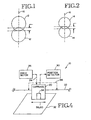
- Fig. 1 shows two overlapping circles 12 of a common size.
- Each circle 12 represents an inkjet printing dot of a first size. Such size is largely exaggerated here for purposes of illustration.
- Fig. 2 shows two overlapping circles 14 having a common second size which is smaller than the first size.
- each circle 14 represents an inkjet printing dot of a second size, and such size is largely exaggerated for purposes of illustration.
- the dots 12 and dots 14 overlap by a common percentage of their respective diameters (e.g., 20%).
- the absolute distance of overlap is larger for the larger dots 12 than for the dots 14.
- the overlap of dots 12 is a distance x.
- the impact to an image formed of the smaller dots 14 is more adverse than to an image formed with the dots 12.
- a vibration amplitude of 0.25x may be acceptable for printing using dots 12.
- the same vibration amplitude equals 0.5y and may cause unacceptable banding when printing with the dots 14.
- Such bands occur within an image at the frequency of vibration of the carriage along the axis 16.
- the smaller dot size and higher resolution of advancing ink jet printers require more accurate placement of dots to achieve expected image quality improvements.
- Any vibrations displacing the carriage relative to the media can potentially reduce printing/scanning accuracy.
- Typical sources of vibration are external vibrations which move the whole printer or scanner, and internal sources which are coupled to the carriage or media. This invention is directed toward internal vibrations which are coupled to the carriage.
- a carriage drive system includes a timing belt pivotally anchored to a carriage.
- a drive motor rotates the timing belt, moving the carriage back and forth along a carriage path.
- the drive belt moves on a pair of pulleys.
- a first pulley is coupled to a shaft of the drive motor.
- a second pulley is coupled to an idler spring.
- the idler spring determines the belt tension when the belt is stationary. Acceleration of the carriage alters the belt tension.
- a pivot connection occurs between the drive belt and the carriage.
- the pivotal connection allows for a lower belt tension during steady state operations (e.g., zero velocity, constant velocity). Rather than maintain the belt at a high tension during rest and steady state periods, the tension is reduced during such periods.
- steady state operations e.g., zero velocity, constant velocity.
- One benefit of the reduction is a decrease in side load to the shaft of the drive motor.
- the motor increases the velocity of the timing belt.
- Such acceleration causes the pivotal connection to rotate. This shortens the effective length of the belt, which in turn increases the force on the idler spring, thereby increasing the belt tension.
- an increase in side load upon the drive shaft is an increase in side load upon the drive shaft.
- the belt tension decreases and the pivotal connection rotates back, decreasing the side load impact on the drive shaft.
- An advantage of the pivotal connection is that belt tension is increased only when needed. During slewing the belt tension is low. During acceleration the belt tension is increased. Another advantage is that large side loads only occur during acceleration. Larger side loads increase friction on the motor bearings, which in turn decreases the motor's thermal margin. Because the larger side loads do not occur during rest and steady state operation, the motor bearings wear longer. Increased side loads also exert a bending moment on the shaft that can fatigue the motor windings and solders joints. The decrease in side load during rest and steady state operation results in a smaller bending moment. Thus, the life of the motor windings and solder joints are prolonged.
- high frequency vibrations in the drive belt are decoupled from the carriage by the pivotal connection. All forces exerted on the carriage through the drive belt are passed through the pivot connection.
- Such pivot connection serves, in effect, as a low pass filter of vibration frequency components occurring in the plane of the pivot motion (e.g., vibrations in the timing belt). Vibration frequencies above a prescribed frequency determined by the pivot connection are absorbed, and thus, are filtered out. Vibrations below such frequency pass to the carriage.
- the spring characteristics of the pivot connection are prescribed so as to isolate the carriage from high frequency ripples in belt tension, such as those caused from motor commutation, stepping or cogging. This allows for smoother carriage motion and less carriage Iift-off, chatter and procession. As a result, print quality is improved for printers with decreasing dot size and increasing precision.
- Fig. 4 shows a carriage drive system 10 having a carriage 20 driven along a carriage path 22 under a drive force 24 generated by a drive motor 26.
- a position detector 30 e.g., linear encoder
- the position detector 30 provides feedback of the carriage position for accurately controlling the movement of the carriage 20 relative to a media 32.
- the carriage carries a device 34 which acts upon the media 32.
- the device 34 is one or more inkjet pens.
- the inkjet pen includes a pen body with an internal reservoir and a printhead.
- the printhead includes an array of printing elements.
- each printing element includes a nozzle chamber, a firing resistor and a nozzle opening. Ink flow from the reservoir into the nozzle chambers, then is heated by activation of the firing resistor. A vapor bubble forms in the nozzle chamber which forces an ink drop to be ejected through the nozzle opening ont the media. Precise control of the ink drop ejection and the relative position of the inkjet pen and media enable formation of characters, symbols and images on the media.
- the device 34 carried by the carriage 20 is one or more optical sensors and the media is a document having markings (e.g., characters, symbols or images).
- markings e.g., characters, symbols or images.
- the optical sensor detects the markings on the document. Precise control of the optical sensor position relative to the document enables an electronic image of the document to be generated.
- software is included which recognizes given marking patterns as given alphanumeric characters.
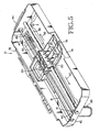
- Figs. 5 and 6 show a perspective view of the carriage drive system 10 according to an embodiment of this invention.
- the carriage 20 is driven along a carriage rod 36.
- the carriage rod is mounted to a carriage plate 38.
- the carriage plate 38 serves as a frame for the carriage drive system 10.
- the drive motor 26 is mounted to the carriage plate 38.
- the drive motor 26 includes a rotating shaft 41 upon which a pulley 40 is mounted.
- the motor 26 and pulley 40 are located toward one end 42 of the drive plate.
- Toward an opposite end 44 a spring-loaded pulley 46 is mounted.
- a drive belt 50 runs along the pulleys 40, 46 and is held in tension by the idler spring 47 which spring-loads the pulley 46.
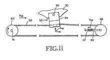
- the drive belt 50 is connected to the carriage 20 through a pivotal connection 52 (see Figs. 6-11) so as to couple the drive force generated by the motor 26 to the carriage 20.
- the drive belt runs along the pulleys 40, 46 causing the carriage 20 to move first in one direction 58, then back in the opposite direction 60 along the carriage rod 36.
- the carriage plate 38 includes an opening 61 which exposes a portion of the carriage 20 to an underlying media.
- Such carriage portion carries the device 34 (e.g., inkjet pen or document scanner sensor).
- the carriage 20 carries a device 34 (see Fig. 4) for printing or scanning a media.
- the carriage 20 also carries a linear encoder module 30.
- a linear encoder strip 31 is fixed relative to the carriage plate 38.
- the strip 31 includes evenly spaced markings.
- the linear encoder module 30 includes an optical sensor which detects and counts such markings so as to track the location of the carriage 20 relative to the strip 31. Because the strip 31 and carriage rod 36 are fixed relative to the carriage plate 38, the linear encoder module 30 is able to detect the carriage position relative to the linear encoder strip 31, the carriage plate 38 and the carriage rod 36.
- Fig. 7 shows an exploded view of the carriage 20 for an inkjet printing embodiment.
- the carriage is formed by a first member 80, a second member 82 and a cap member 84.
- the second member 82 and cap member 84 are attached to the first member 80.
- the first member 80 includes a first portion 62 for carrying an inkjet pen device 34 (see Fig. 4) and a second portion 64 for receiving the second member 82 and cap member 84.
- the second member 82 houses the linear encoder module and other electronic circuitry (e.g., print control circuitry, print memory).
- the second member 82 includes a slot 86 through which the linear encoder strip 31 runs during movement of the carriage 20.
- the second member 82 also includes the pivotal connection 52 which couples the carriage 20 to the drive belt 50.
- the cap member 84 covers the linear encoder module 30 and electronic circuitry.
- the first member 80 includes an opening 66 which extends through a center area and receives the carriage rod 36. With the pen(s) loaded and the electronic circuitry mounted, the center of gravity 68 of the carriage 20 is located slightly forward and down of the opening 66 center point toward the first portion 62. Thus, as the carriage 20 moves along the carriage rod 36 there is a moment arm 70 about the carriage rod 36 which biases a distal end 72 of the carriage 20 toward a first surface 74 of the carriage plate 38. A roller 76 is mounted to the carriage 20 first portion 62 toward the distal end 72. Under the gravitational force of the moment arm 70, the roller 76 resides in contact with the carriage plate first surface 74. As the carriage 20 moves along the carriage rod 36, the roller 76 runs along the first surface 74.
- a pivotal connection 52 is mounted to the carriage 20 as shown in Figs. 6-8.
- the connection 52 includes an axle 92 and a frame 94.
- the axle 92 is fixed to the carriage 20.
- the frame 94 rotates about the axle 92.
- the drive belt 50 is fastened, anchored or otherwise fixedly positioned relative to the frame 94.
- the drive belt 50 includes a protrusion 96 which mates into an opening 98 in the frame 94. Such protrusion 96 fixes the drive belt 50 relative to the frame 94.
- the motor shaft 41 moves the drive belt 50 along the pulleys 40, 46.
- the movement of the drive belt 50 exerts a drive force on the carriage 20 moving the carriage 20 along a carriage path defined by the carriage rod 36.
- the drive force originates at the drive motor 26 and is translated to the carriage 20 through the drive shaft 41, drive belt 50 and pivotal connection 52.
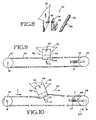
- Fig. 9 shows the carriage 20 at a rest position where the known angle ⁇ rest is 90 degrees. As the carriage 20 moves, the carriage exerts a side load onto the drive shaft 41 and drive motor 26.
- Fig. 10 shows the carriage 20 being accelerated in a direction 60 in response to a drive force F.
- the acceleration causes the drive belt 50 to lead and the pivot frame 94 to offset so that the carriage lags at the pivot connection 52.
- Such lag appears as an angular offset at the pivot connection 52.
- the frame 94 rotates about the axle 92 to be offset at an offset angle ⁇ F relative to the carriage path.
- the drive force F also acts on the spring-loaded pulley 46 pulling the spring-loaded pulley 46 toward the drive motor pulley 40 by an incremental distance Ax. This increases the tension in the drive belt 50.
- the increase in the drive belt tension is determined by the drive force F.
- the increased tension is absorbed by the pulley 46 or a post 49 connecting the spring 47 to the pulley 46, without expanding the spring 47 so as to simplify the system dynamics.
- the motor 26 rotates the shaft 41 at a constant velocity.
- the drive belt 50 moves at a constant velocity.
- the effect is that the force F decreases (to a value F ss needed to overcome friction).
- the reduced allows the pivot connection 52 to rotate back toward its rest position into a steady state position ⁇ ss , where ⁇ ss is at the same angle as the rest position angle ⁇ rest or is slightly offset from such angle.
- the belt tension during this steady state motion is less than a corresponding belt tension in a system having a rigid connection between the drive belt 50 and the carriage 20 or in a system having a non-rotating connection 52 (as shown in Figs. 8-10).
- An advantage of the pivotal connection 52 is that belt tension is increased only when needed. During slewing the belt tension is low. During acceleration the belt tension is increased. Larger side loads increase friction on the motor bearings, which in turn decrease the motor's thermal margin. The rest and steady state periods of substantially less side load allow the motor bearings to wear longer. The larger side loads also exert a bending moment on the shaft 41 that can fatigue the windings and solders joints of a drive motor 26. The rest and steady state periods of substantially less side load allow for periods of a differentially smaller bending moment. Thus, the life of the motor windings and solder joints are prolonged.
- the pivot connection 52 also serves to isolate the carriage 20 from high frequency vibrations occurring in the drive belt 50.
- the motor 26 generates the drive force 24 to move the carriage 20 along the carriage rod 36
- the drive force is transmitted to the carriage through the pivot connection 52.
- the pivot connection 52 is biased by the drive force to rotate in one direction.
- pivot connection 52 is biased by the drive force to rotate in another direction.
- vibrations occur the belt tension jitters causing the angle of the pivot connection 52 to correspondingly jitter so as to absorb the vibrations.
- the pivot connection 52 serves as a low pass filter which absorbs the high frequency vibrations and passes the low frequency vibrations (e.g., the drive force first frequency).
- Low frequency vibrations which are not filtered out by the pivot connection 52 are compensated for by the linear encoder module 30.
- the linear encoder serves to detect carriage position. Carriage position is monitored so that ink dots can be accurately placed on a media sheet or markings can be accurately detected.
- the linear encoder detects carriage position independently of the motor shaft 41 rotation. As a result, vibrations in the motor shaft are not coupled into the position detection scheme.
- the linear encoder is able to detect the carriage position even in the presence of carriage vibrations.
- Such vibrations move the linear encoder module 30 relative to the linear encoder strip 31.
- carriage position is detected during portion of a vibration period. More specifically though, low frequency vibrations occurring at a frequency less than the sampling rate of the linear encoder and of an amplitude detectable by the linear encoder are detected by the linear encoder.
Landscapes
- Character Spaces And Line Spaces In Printers (AREA)
- Ink Jet (AREA)
Claims (6)
- Système de balayage de chariot (10) comprenant :dans lequel le coupleur isole le chariot des vibrations se produisant dans la courroie d'entraínement, dans lequel le chariot exerce une charge latérale sur le moteur par le biais du coupleur et de la courroie d'entraínement, et dans lequel le couplage pivotant réduit la charge latérale du chariot sur le moteur lors du déplacement à vitesse constante du chariot.un chariot (20) se déplaçant le long d'un trajet de chariot ;un moteur d'entraínement (26) générant une force d'entraínement (F) ; etune courroie d'entraínement (50) couplée au moteur d'entraínement et couplée indirectement au chariot, laquelle courroie d'entraínement transmet la force d'entraínement au chariot de manière à déplacer celui-ci le long du trajet de chariot ; etun coupleur (52) monté pivotant sur le chariot et couplé à la courroie d'entraínement ;
- Système, selon la revendication 1, dans lequel le moteur comprend un arbre de moteur (41), le système comprenant en outre une première poulie (40) couplée à l'arbre du moteur et une seconde poulie (46) ancrée par un ressort flottant (47), système dans lequel la courroie d'entraínement passe le long de la première poulie et de la seconde poulie, et dans lequel le coupleur pivote pendant l'accélération du chariot.
- Système d'impression à jets d'encre (10) permettant d'imprimer sur une feuille de support (32), et comprenant .dans lequel le coupleur isole le chariot des vibrations se produisant dans la courroie d'entraínement, dans lequel le chariot exerce une charge latérale sur le moteur par le biais du coupleur et de la courroie d'entraínement, et dans lequel le couplage pivotant réduit la charge latérale du chariot sur le moteur lors du déplacement à vitesse constante du chariot.un cadre (38) ;une tige de chariot (36) montée sur le cadre ;un chariot (20) se déplaçant le long de la tige de chariot ;un stylo à jets d'encre (34) monté dans le chariot et servant à éjecter des gouttelettes d'encre lors du déplacement du chariot le long de la tige de chariot ;un coupleur (52) monté pivotant sur le chariot ;un moteur d'entraínement (26) générant une force d' entraínement (F) ; etune courroie d'entraínement (50) couplée au moteur d'entraínement et couplée indirectement au chariot par le biais du coupleur monté pivotant, laquelle courroie d'entraínement transmet la force d'entraínement au chariot de manière à déplacer celui-ci le long du trajet de chariot ;
- Système d'impression, selon la revendication 3, dans lequel le moteur comprend un arbre de moteur (41), le système comprenant en outre une première poulie (40) couplée à l'arbre du moteur et une seconde poulie (46) ancrée par un ressort flottant (47), système dans lequel la courroie d'entraínement passe le long de la première poulie et de la seconde poulie, et dans lequel le coupleur pivote pendant l'accélération du chariot.
- Système de numérisation de documents (10) comprenant :dans lequel le coupleur isole le chariot des vibrations se produisant dans la courroie d'entraínement, dans lequel le chariot exerce une charge latérale sur le moteur par le biais du coupleur et de la courroie d'entraínement, et dans lequel le couplage pivotant réduit la charge latérale du chariot sur le moteur lors du déplacement à vitesse constante du chariot.un cadre ( 38 ) ;une tige de chariot (36) montée sur le cadre ;un chariot (20) se déplaçant le long de la tige de chariot ;un capteur optique (34) monté sur le chariot et permettant de numériser un document lors du déplacement du chariot le long de la tige de chariot ;un coupleur (52) monté pivotant sur le chariot ;un moteur d'entraínement (26) générant une force d'entraínement (F) ; etune courroie d'entraínement (50) couplée au moteur d'entraínement et couplée indirectement au chariot par le biais du coupleur, laquelle courroie d'entraínement transmet la force d'entraínement au chariot de manière à déplacer celui-ci le long du trajet de chariot ;
- système de numérisation, selon la revendication 3, dans lequel le moteur comprend un arbre de moteur (41), le système comprenant en outre une première poulie (40) couplée à l'arbre du moteur et une seconde poulie (46) ancrée par un ressort flottant (47), système dans lequel la courroie d'entraínement passe le long de la première poulie et de la seconde poulie, et dans lequel le coupleur pivote pendant l'accélération du chariot.
Applications Claiming Priority (2)
| Application Number | Priority Date | Filing Date | Title |
|---|---|---|---|
| US09/089,925 US5964542A (en) | 1998-06-03 | 1998-06-03 | Carriage system with variable belt tension |
| US89925 | 1998-06-03 |
Publications (3)
| Publication Number | Publication Date |
|---|---|
| EP0962327A2 EP0962327A2 (fr) | 1999-12-08 |
| EP0962327A3 EP0962327A3 (fr) | 2000-02-23 |
| EP0962327B1 true EP0962327B1 (fr) | 2003-09-24 |
Family
ID=22220249
Family Applications (1)
| Application Number | Title | Priority Date | Filing Date |
|---|---|---|---|
| EP99303851A Expired - Lifetime EP0962327B1 (fr) | 1998-06-03 | 1999-05-18 | Système d'entraínement du chariot avec tension variable d'une courroie |
Country Status (4)
| Country | Link |
|---|---|
| US (1) | US5964542A (fr) |
| EP (1) | EP0962327B1 (fr) |
| DE (1) | DE69911500T2 (fr) |
| ES (1) | ES2203017T3 (fr) |
Families Citing this family (23)
| Publication number | Priority date | Publication date | Assignee | Title |
|---|---|---|---|---|
| US6045212A (en) * | 1998-07-30 | 2000-04-04 | Hewlett-Packard Company | Integral spring drive belt system for inkjet carriages |
| US6819448B2 (en) * | 1998-09-28 | 2004-11-16 | Hewlett-Packard Development Company, L.P. | Printer with print mode masking periodic carriage vibration |
| US6244765B1 (en) * | 1999-06-30 | 2001-06-12 | Hewlett-Packard Company | Vibration isolating attachment system for inkjet carriages |
| US6340221B1 (en) | 2000-09-18 | 2002-01-22 | Hewlett-Packard Company | Ink jet print carriage drive system that applies drive force at location displaced from drive belt |
| US6485207B1 (en) | 2001-03-07 | 2002-11-26 | Eugene David Allen | Printer assembly providing tension for idler pulley |
| US6598956B2 (en) | 2001-10-19 | 2003-07-29 | Hewlett-Packard Development Company, L.P. | Carriage drive belt with compliant belt section for carriage attachment |
| US6508534B1 (en) * | 2001-10-19 | 2003-01-21 | Hewlett-Packard Company | Carriage drive belt with compliant belt section for inkjet printer |
| TWI247529B (en) * | 2002-06-17 | 2006-01-11 | Primax Electronics Ltd | Belt tension adjustment apparatus and a scanner using the same |
| GB2392874A (en) * | 2002-09-13 | 2004-03-17 | Pryor Edward & Son | High speed marker having a marking head mounted on a drive screw for linear movement in a first axis and rotatable thereon for movement in a second axis |
| US6893111B2 (en) * | 2002-10-03 | 2005-05-17 | Lexmark International, Inc. | Imaging apparatus having a printhead carrier/belt interface device |
| US6896430B2 (en) * | 2002-10-23 | 2005-05-24 | Hewlett-Packard Development Company, L.P. | Compliant belt attach |
| KR100470584B1 (ko) * | 2002-11-06 | 2005-03-08 | 삼성전자주식회사 | 사무기기의 풀리 고정장치 |
| TWI227084B (en) * | 2003-03-21 | 2005-01-21 | Primax Electronics Ltd | Flatbed scanner and scan module thereof |
| US7364261B2 (en) * | 2004-03-10 | 2008-04-29 | Lexmark International, Inc. | Directionally dependent carrier isolator for an imaging apparatus |
| JP2006095697A (ja) * | 2004-09-28 | 2006-04-13 | Seiko Epson Corp | キャリッジの駆動制御方法及び駆動制御プログラム並びに電子装置、記録装置及び液体噴射装置 |
| US7677718B2 (en) * | 2004-12-17 | 2010-03-16 | Hewlett-Packard Development Company, L.P. | Flexible member having tensioning members |
| US8774681B2 (en) * | 2007-10-31 | 2014-07-08 | Hewlett-Packard Development Company, L.P. | Scanner having driven member tension |
| US8295983B2 (en) * | 2008-11-10 | 2012-10-23 | Silent Printer Holdings, Llc | Apparatus and method for characterization and control of usage disturbances in a usage environment of printers and other dynamic systems |
| TW201238786A (en) * | 2011-03-28 | 2012-10-01 | Hon Hai Prec Ind Co Ltd | Adjusting device and electronic apparatus with adjusting device |
| JP2015174765A (ja) * | 2014-03-18 | 2015-10-05 | 船井電機株式会社 | 画像形成装置 |
| JP6642796B2 (ja) * | 2016-02-26 | 2020-02-12 | セイコーエプソン株式会社 | 画像読取装置及び記録装置 |
| CN109993910A (zh) * | 2017-12-29 | 2019-07-09 | 山东新北洋信息技术股份有限公司 | 传送带连接组件、隔板组件及其自动售货机 |
| CN112576715A (zh) * | 2020-12-02 | 2021-03-30 | 黄石市中城自动化科技有限公司 | 一种同步带新型传动机构 |
Family Cites Families (11)
| Publication number | Priority date | Publication date | Assignee | Title |
|---|---|---|---|---|
| US3908809A (en) * | 1974-12-30 | 1975-09-30 | Ibm | High speed printer |
| DE2610771C3 (de) * | 1976-03-15 | 1979-10-11 | Siemens Ag, 1000 Berlin Und 8000 Muenchen | Antriebsvorrichtung für Schreibwagen in Tintenstrahlschreibeinrichtungen |
| JPS595083A (ja) * | 1982-06-30 | 1984-01-11 | Tokyo Electric Co Ltd | シリアルプリンタ |
| JPS59111878A (ja) * | 1982-12-16 | 1984-06-28 | Tokyo Electric Co Ltd | シリアルプリンタのキヤリア防振装置 |
| JPS6299178A (ja) * | 1985-10-28 | 1987-05-08 | Ricoh Co Ltd | 印字装置 |
| DE3608000A1 (de) * | 1986-03-11 | 1987-09-24 | Mannesmann Ag | Einrichtung fuer den antrieb eines druckkopfschlittens fuer einen drucker, insbesondere fuer einen matrixdrucker |
| DE3822129A1 (de) * | 1988-06-30 | 1990-01-04 | Siemens Ag | Vorrichtung zur robotergerechten montage von zahnriemen |
| US4914726A (en) * | 1989-01-17 | 1990-04-03 | Tektronix, Inc. | Mass velocity controller |
| US5415483A (en) * | 1993-08-20 | 1995-05-16 | Tooling Research, Inc. | Sealed linear positioning apparatus |
| JPH09234926A (ja) * | 1996-02-28 | 1997-09-09 | Ricoh Co Ltd | シリアルプリンタシステム |
| US5779376A (en) * | 1996-10-31 | 1998-07-14 | Hewlett-Packard Company | Printer carriage drive with movably mounted motor |
-
1998
- 1998-06-03 US US09/089,925 patent/US5964542A/en not_active Expired - Lifetime
-
1999
- 1999-05-18 EP EP99303851A patent/EP0962327B1/fr not_active Expired - Lifetime
- 1999-05-18 DE DE69911500T patent/DE69911500T2/de not_active Expired - Lifetime
- 1999-05-18 ES ES99303851T patent/ES2203017T3/es not_active Expired - Lifetime
Also Published As
| Publication number | Publication date |
|---|---|
| EP0962327A3 (fr) | 2000-02-23 |
| DE69911500D1 (de) | 2003-10-30 |
| ES2203017T3 (es) | 2004-04-01 |
| EP0962327A2 (fr) | 1999-12-08 |
| DE69911500T2 (de) | 2004-07-22 |
| US5964542A (en) | 1999-10-12 |
Similar Documents
| Publication | Publication Date | Title |
|---|---|---|
| EP0962327B1 (fr) | Système d'entraínement du chariot avec tension variable d'une courroie | |
| EP0630750B1 (fr) | Appareil d'enregistrement ayant un mécanisme de réglage de la déviation | |
| EP1201581B1 (fr) | Procédé de commande d'un appareil de transport de feuilles et procédé de commande d'un appareil d'enregistrement | |
| EP0664221B1 (fr) | Appareil d'impression sérielle contrÔlé de boucle ouverte | |
| US6004050A (en) | Carriage scanning system with carriage isolated from high frequency vibrations in drive belt | |
| US5924809A (en) | Rotational vibration isolation of carriage about carriage rod during carriage movement | |
| KR20040084010A (ko) | 헤드 갭 조절장치가 적용된 잉크젯프린터 | |
| US6027211A (en) | Sheet feeding apparatus and recording apparatus | |
| US6310638B1 (en) | Carriage bearing preloader and antirotation restoring force for reducing carriage vibration | |
| US6406110B1 (en) | Mechanism to automate adjustment of printhead-to-print medium gap spacing on an imaging apparatus | |
| US5852452A (en) | Ink jet printer with adjustable capping mechanism and printing cap | |
| KR100612451B1 (ko) | 화상 형성 장치의 인쇄 매체 인식 장치 및 그 방법 | |
| US6890047B2 (en) | Printing apparatus and printing method | |
| JP2003080786A (ja) | 記録装置 | |
| JPH10337862A (ja) | インクジェット式記録装置 | |
| JP4367609B2 (ja) | キャリッジ、該キャリッジを備えた液体噴射装置 | |
| JPH0994948A (ja) | インクジェットプリンタ | |
| JP2009119764A (ja) | 液体噴射装置 | |
| JPH03234534A (ja) | インクジェット記録装置 | |
| JP3509706B2 (ja) | インクジェット式記録装置 | |
| JP2002307773A (ja) | プリンタ制御装置及びプリンタ制御方法並びにプリンタ | |
| JP2002340116A (ja) | ベルト駆動装置及び該ベルト駆動装置を用いる記録装置 | |
| JPH09240098A (ja) | 記録装置及びその方法 | |
| JPH0880647A (ja) | 記録装置 | |
| JPH02238975A (ja) | 印字ヘッドの支持機構 |
Legal Events
| Date | Code | Title | Description |
|---|---|---|---|
| PUAI | Public reference made under article 153(3) epc to a published international application that has entered the european phase |
Free format text: ORIGINAL CODE: 0009012 |
|
| AK | Designated contracting states |
Kind code of ref document: A2 Designated state(s): DE ES GB |
|
| AX | Request for extension of the european patent |
Free format text: AL;LT;LV;MK;RO;SI |
|
| PUAL | Search report despatched |
Free format text: ORIGINAL CODE: 0009013 |
|
| AK | Designated contracting states |
Kind code of ref document: A3 Designated state(s): AT BE CH CY DE DK ES FI FR GB GR IE IT LI LU MC NL PT SE |
|
| AX | Request for extension of the european patent |
Free format text: AL;LT;LV;MK;RO;SI |
|
| RIN1 | Information on inventor provided before grant (corrected) |
Inventor name: WOTTON, GEOFF Inventor name: QUINTANA, JASON Inventor name: RUHE, THOMAS W. |
|
| 17P | Request for examination filed |
Effective date: 20000602 |
|
| AKX | Designation fees paid |
Free format text: DE ES GB |
|
| RAP1 | Party data changed (applicant data changed or rights of an application transferred) |
Owner name: HEWLETT-PACKARD COMPANY, A DELAWARE CORPORATION |
|
| GRAH | Despatch of communication of intention to grant a patent |
Free format text: ORIGINAL CODE: EPIDOS IGRA |
|
| GRAS | Grant fee paid |
Free format text: ORIGINAL CODE: EPIDOSNIGR3 |
|
| GRAA | (expected) grant |
Free format text: ORIGINAL CODE: 0009210 |
|
| AK | Designated contracting states |
Kind code of ref document: B1 Designated state(s): DE ES GB |
|
| REG | Reference to a national code |
Ref country code: GB Ref legal event code: FG4D |
|
| REF | Corresponds to: |
Ref document number: 69911500 Country of ref document: DE Date of ref document: 20031030 Kind code of ref document: P |
|
| REG | Reference to a national code |
Ref country code: ES Ref legal event code: FG2A Ref document number: 2203017 Country of ref document: ES Kind code of ref document: T3 |
|
| PLBE | No opposition filed within time limit |
Free format text: ORIGINAL CODE: 0009261 |
|
| STAA | Information on the status of an ep patent application or granted ep patent |
Free format text: STATUS: NO OPPOSITION FILED WITHIN TIME LIMIT |
|
| 26N | No opposition filed |
Effective date: 20040625 |
|
| PGFP | Annual fee paid to national office [announced via postgrant information from national office to epo] |
Ref country code: ES Payment date: 20070528 Year of fee payment: 9 |
|
| PGFP | Annual fee paid to national office [announced via postgrant information from national office to epo] |
Ref country code: GB Payment date: 20080529 Year of fee payment: 10 |
|
| REG | Reference to a national code |
Ref country code: ES Ref legal event code: FD2A Effective date: 20080519 |
|
| PG25 | Lapsed in a contracting state [announced via postgrant information from national office to epo] |
Ref country code: ES Free format text: LAPSE BECAUSE OF NON-PAYMENT OF DUE FEES Effective date: 20080519 |
|
| GBPC | Gb: european patent ceased through non-payment of renewal fee |
Effective date: 20090518 |
|
| PG25 | Lapsed in a contracting state [announced via postgrant information from national office to epo] |
Ref country code: GB Free format text: LAPSE BECAUSE OF NON-PAYMENT OF DUE FEES Effective date: 20090518 |
|
| PGFP | Annual fee paid to national office [announced via postgrant information from national office to epo] |
Ref country code: DE Payment date: 20130423 Year of fee payment: 15 |
|
| REG | Reference to a national code |
Ref country code: DE Ref legal event code: R119 Ref document number: 69911500 Country of ref document: DE |
|
| REG | Reference to a national code |
Ref country code: DE Ref legal event code: R119 Ref document number: 69911500 Country of ref document: DE Effective date: 20141202 |
|
| PG25 | Lapsed in a contracting state [announced via postgrant information from national office to epo] |
Ref country code: DE Free format text: LAPSE BECAUSE OF NON-PAYMENT OF DUE FEES Effective date: 20141202 |