EP0962309A2 - Machine de fabrication de sacs et procédé pour la fabrication de sacs - Google Patents
Machine de fabrication de sacs et procédé pour la fabrication de sacs Download PDFInfo
- Publication number
- EP0962309A2 EP0962309A2 EP99107472A EP99107472A EP0962309A2 EP 0962309 A2 EP0962309 A2 EP 0962309A2 EP 99107472 A EP99107472 A EP 99107472A EP 99107472 A EP99107472 A EP 99107472A EP 0962309 A2 EP0962309 A2 EP 0962309A2
- Authority
- EP
- European Patent Office
- Prior art keywords
- film
- foils
- foil
- bag
- stretching
- Prior art date
- Legal status (The legal status is an assumption and is not a legal conclusion. Google has not performed a legal analysis and makes no representation as to the accuracy of the status listed.)
- Granted
Links
Images


Classifications
-
- B—PERFORMING OPERATIONS; TRANSPORTING
- B65—CONVEYING; PACKING; STORING; HANDLING THIN OR FILAMENTARY MATERIAL
- B65B—MACHINES, APPARATUS OR DEVICES FOR, OR METHODS OF, PACKAGING ARTICLES OR MATERIALS; UNPACKING
- B65B41/00—Supplying or feeding container-forming sheets or wrapping material
-
- B—PERFORMING OPERATIONS; TRANSPORTING
- B31—MAKING ARTICLES OF PAPER, CARDBOARD OR MATERIAL WORKED IN A MANNER ANALOGOUS TO PAPER; WORKING PAPER, CARDBOARD OR MATERIAL WORKED IN A MANNER ANALOGOUS TO PAPER
- B31B—MAKING CONTAINERS OF PAPER, CARDBOARD OR MATERIAL WORKED IN A MANNER ANALOGOUS TO PAPER
- B31B70/00—Making flexible containers, e.g. envelopes or bags
- B31B70/74—Auxiliary operations
-
- B—PERFORMING OPERATIONS; TRANSPORTING
- B31—MAKING ARTICLES OF PAPER, CARDBOARD OR MATERIAL WORKED IN A MANNER ANALOGOUS TO PAPER; WORKING PAPER, CARDBOARD OR MATERIAL WORKED IN A MANNER ANALOGOUS TO PAPER
- B31B—MAKING CONTAINERS OF PAPER, CARDBOARD OR MATERIAL WORKED IN A MANNER ANALOGOUS TO PAPER
- B31B2155/00—Flexible containers made from webs
- B31B2155/002—Flexible containers made from webs by joining superimposed webs, e.g. with separate bottom webs
-
- B—PERFORMING OPERATIONS; TRANSPORTING
- B31—MAKING ARTICLES OF PAPER, CARDBOARD OR MATERIAL WORKED IN A MANNER ANALOGOUS TO PAPER; WORKING PAPER, CARDBOARD OR MATERIAL WORKED IN A MANNER ANALOGOUS TO PAPER
- B31B—MAKING CONTAINERS OF PAPER, CARDBOARD OR MATERIAL WORKED IN A MANNER ANALOGOUS TO PAPER
- B31B2160/00—Shape of flexible containers
- B31B2160/10—Shape of flexible containers rectangular and flat, i.e. without structural provision for thickness of contents
-
- B—PERFORMING OPERATIONS; TRANSPORTING
- B31—MAKING ARTICLES OF PAPER, CARDBOARD OR MATERIAL WORKED IN A MANNER ANALOGOUS TO PAPER; WORKING PAPER, CARDBOARD OR MATERIAL WORKED IN A MANNER ANALOGOUS TO PAPER
- B31B—MAKING CONTAINERS OF PAPER, CARDBOARD OR MATERIAL WORKED IN A MANNER ANALOGOUS TO PAPER
- B31B2160/00—Shape of flexible containers
- B31B2160/20—Shape of flexible containers with structural provision for thickness of contents
-
- B—PERFORMING OPERATIONS; TRANSPORTING
- B31—MAKING ARTICLES OF PAPER, CARDBOARD OR MATERIAL WORKED IN A MANNER ANALOGOUS TO PAPER; WORKING PAPER, CARDBOARD OR MATERIAL WORKED IN A MANNER ANALOGOUS TO PAPER
- B31B—MAKING CONTAINERS OF PAPER, CARDBOARD OR MATERIAL WORKED IN A MANNER ANALOGOUS TO PAPER
- B31B70/00—Making flexible containers, e.g. envelopes or bags
- B31B70/02—Feeding or positioning sheets, blanks or webs
- B31B70/10—Feeding or positioning webs
Definitions
- the invention relates to a method for producing foil bags, in which at least two foils, which serve as side foils of the foil pouches, placed on top of one another, interconnected and cut into individual foil bags, and one Bag manufacturing device for performing the method.
- a film bag manufacturing process at least two films are fed serve as side foils of the foil pouch.
- the feed is generally from corresponding supply rolls.
- the individual foils are placed on top of each other and at least where the side edges of the foil bags will be welded or glued.
- a bottom film can be placed between the side films, which in the area of the future bottom of the foil bag welded or glued between the side foils and by unfolding it offers space for the contents. Also takes over this floor film is a stand-up function.
- the so produced and on three side edges sealed foil bags can then e.g. fed to a filling station the filling material is filled in through the fourth edge which has not yet been closed and then this fourth edge of the two side foils is welded together or glued.
- the film strands that are fed to the welding device are usually already with appropriate imprints on the product to be contained in the foil bag Mistake. So is already before feeding to the welding or gluing device for each individual strand of film defines exactly how much film material for a film bag is provided in each case. However, slight deviations in the provided for a film bag amount of film material. This can e.g. be caused by an imprecise printing machine for printing. Furthermore result from the rolling process on the supply roll different Elongations for the film material, depending on whether a lot or little on the supply roll Foil material is rolled up.
- the object of the present invention is therefore a method and a device indicate the deviations in the amount of film material for the individual sides of the film bag is provided can be prevented.
- At least two strands of film are first used fed, which are to form the side films of the film bag.
- the foils are placed on top of each other and connected to each other at the future side edges of the foil bags. Possibly. Differences occurring in the amount of film material from the least two films are provided in the feed direction for one film bag each compensated by stretching the film that the smaller one for a film bag Provides amount of film material.
- a process step is introduced before the adhesive or welding process, which leads to the compensation of the possibly different amounts of film material.
- This ensures that the individual film strands are aligned with one another come to rest before they are connected. A little, if any Offset can be prevented in this way, so that the accumulation of the Misalignment is prevented.
- the stretching can be realized in a simple manner if the film feed is too stretching film is briefly interrupted or slowed down during removal continues after the connection process. This way it becomes dependent on the necessary stretch controlled the film feed. Interrupting the film feed can e.g. can be achieved by means of clamps which act on the supplied film, if this film is to be stretched.
- the stretching is achieved by holding the stretching film at two spaced locations and simultaneously increasing the film tension reached between the stops. This procedure enables one very precise stretching of the film. It can be provided that the film on the Stopping points is firmly clamped, so that the stretch in the film section between the breakpoints happens.
- the film tension can be increased in a simple manner with the aid of a stretching body can be achieved, the film to be stretched over the entire width between the two stops laterally deflected from the unaffected transport path. Through the lateral deflection, the film web is stretched.
- Which of the stretching devices on the at least two supplied foils is active depends on which of the film webs is to be stretched. This can be done automatically take place or be controlled manually. Are the film material quantities each of the at least two films in the feed direction for one film bag each are approximately the same for the two foils, it may be advantageous if one of the foils e.g. permanently stretched by a slower feed becomes. The other film is then correspondingly in accordance with the inventive method stretched.
- markings are provided on the supplied film, which are applied to the film material at intervals equal to the amount of film material correspond, which is provided for a film bag.
- markings can easily determine how much film material the respective film is provided for a film bag. Is the distance of each Markings smaller than the extent that a future foil bag in the feed direction should have a corresponding stretch on this film material carried out until the respective markings have the desired distance.
- the markings can be formed by notches, holes or structural features become.
- Such a marking can easily be made on the film material to be fed Print in advance, e.g. in the process in which the inscription on the future Foil bag is applied to the film. There is no additional procedural step necessary.
- optical markings can be detected very easily and evaluate.
- markings can be applied in an area of the supplied film material be cut off before the photo bag is finally formed. Especially however, it is economical if the marking is provided in an area which later forms the side film of a respective film bag. That way needs no foil material is wasted to remove the marking.
- a marker, that can be read optically can be very small and accordingly not be disruptive.
- the optical marking in the integrate the existing imprint of the foil bag anyway, or it can be part of the existing print itself can be used as an optical marking.
- the process can be carried out on film strands that are perpendicular to a width to the feed direction, which corresponds exactly to a foil bag.
- the method can be used if the film material supplied is a Has width that corresponds to several foil bags, so that several foil bags side by side and be subjected to the individual production steps at the same time.
- the film bags produced side by side are then in a subsequent Process separated.
- a parallel process is a single marking, each valid for a series of foil bags produced in parallel is sufficient.
- the bag manufacturing device according to the invention for performing the inventive The method has a measuring device for detecting the amount of film material of the films fed in each case, which is in the feed direction for the production one foil bag is provided. Furthermore, the bag manufacturing device according to the invention an extension device for each sheet fed, the is designed such that, in response to a signal from the measuring device, the respective Film stretches.
- a number of optical sensors for detecting markings are advantageous provided on the supplied foils from which the amount of foils are determined can be provided by the individual foils to form a single foil pouch becomes.
- Such optical sensors allow precise measurement in a simple manner.
- the signal from the optical sensors can be used directly to provide a corresponding To trigger stretching by the stretching device.
- foils processed the extent of which is perpendicular to the direction of feed several Corresponds to foil bags, so is a single sensor along the width of the supplied Foil sufficient to determine the amount of film material used by each Foil for the production of a foil bag is provided.
- Differences in the feed speed can also be caused by the stretching device of the individual film materials are balanced. These are advantageous however, balanced with the aid of tensioning devices which upstream the film Apply constant tension to the extension device. This is for Increased precision in film feeding.
- both the method and the device a welding process is provided as a connection mechanism for the individual foils.
- FIG 3 shows a finished foil pouch, e.g. for drinks is provided.
- the foil bag 2 consists of two side foils that run along the Side edges 8 are welded together. In the bottom area is the one shown Example, a base film is welded in the area 10 in between. In this way the film bag 2 has an expansion after unfolding the bottom film, the Space for the filling e.g. the drink that provides. Following the filling process the film bag is welded to the upper edge 12 to be closed become.
- On the side foils are e.g. Imprints 14 on the content of the foil bag intended.
- a foil bag is near the bottom edge a mark 16 is provided on the respective side foils.
- the material of the foil pouch can e.g. Be aluminum laminate film.
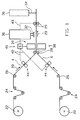
- FIG. 1 22 denotes supply rolls on which film strands form the side films are already rolled up on the side foils the imprint 14 for the individual Foils provided, the feeding of the bottom foil is not shown for the sake of clarity.
- the individual foils 4, 6 are e.g. by known, spring-loaded Clamping devices 24 and guided around pulleys 26 and 28. 29 designated a take-off device for the interconnected foils, e.g. rotating rollers, which promote the welded foils in direction 20 by friction.
- Designated 32 the welding head of a welding device 30 and 34 denotes the knife one Cutting device 36 which extends across the width of the film.
- a measuring device which e.g. by two optical sensors 38, 39 is formed, which is arranged above and below the merged film strand to detect markings on it.
- the optical measuring device is connected to a controller 40, which in turn is connected via signal lines 42 Clamping devices 44 are coupled, which act on the supplied film strands can.
- Figure 2 shows a section of a supplied film.
- the direction of the film strand is again designated 20.
- 18 denotes the cut edges along which the Cutting device 36 is intended to cut the film strand into individual film bags.
- Markings 16 are in the embodiment shown along such a future one Cutting edge provided. They are already together with the imprints 14 printed on the film for the individual film bags, which are pulled off the supply roll 20 becomes. In the embodiment shown, two foil bags become vertical machined simultaneously to the direction of rotation.
- FIGS 4a and 4b show an extension device 46, which is in another embodiment the device according to the invention instead of the clamp devices 44 is used.
- 4 in turn denotes a film strand that is to be stretched.
- Holding devices 48 and 50 are at a distance 60 in the feed direction 20 of the film intended.
- the holding devices are e.g. Brackets that are perpendicular to the direction of transport 20 of the film can be moved towards each other.
- An extension body 52 in the form of a piston which is movable in direction 58 is arranged such that he can move towards film 4 in direction 58.
- the extension body 52 extends also over the entire width of the film material 4.
- Strands of film are from the film rolls 22 unrolled. This happens e.g. by the tensile force exerted by the discharge device 29 e.g. by frictional engagement of appropriate conveyor rollers on the film strand The removal speed becomes constant at the location of the removal rollers 29 held.
- the respective film strands 4, 6 are joined by a tensioning device 24 a substantially constant tension is applied before passing through pulleys 26 and 28 are merged.
- a tensioning device 24 a substantially constant tension is applied before passing through pulleys 26 and 28 are merged.
- In the illustration of Figure 1 are on the upper film strand 4 of Figure 2 corresponding imprints 14 on the top pointing side.
- there is a lower one Foil strand 6 corresponding or different prints on the downward facing Page.
- the optical measuring devices 38, 39, 39 detects the individual Markings 16 on the upper film strand, while 38 the markings on the lower film strand detected.
- Corresponding signals from these optical measuring devices 38, 39 are forwarded to the controller 40, which results from the speed the discharge device 29, which is fed to the controller 40 via the signal line 43 the distance between the individual markings 16 for both the upper and for the lower film strand 4 or 6 is calculated.
- a difference in the distances results from the measurement of the measuring devices 38, 39 the individual markings from one film strand 4 to the other film strand 6, the controller 40 thus sends a signal to the clamp 44 which is assigned to the film strand is on which the markings 16 have a smaller distance than on the other Foil strand.
- the corresponding bracket 44 briefly engages the corresponding one Foil strand on. The fact that the discharge speed of the discharge rollers 29 remains constant, the shorter film is stretched while the other film is not stretched.
- the bracket 44 which is the control signal 40 remains closed until the difference in the distances of the Markings 16 on the respective film strands is balanced.
- the controller 40 can measure the measured Distance of the individual markings 16 in the feed direction also with a Compare the specified target distance. This is a comparison of the individual Gaps on the two different foils are superfluous.
- the stretching device 46 With an embodiment of the device according to the invention, the stretching device 46 according to Figures 4a and b, the stretching is as follows carried out. If one of the measuring devices 38, 39 determines that a film must be stretched, a signal is given to the stretching device 46. The Holding devices 48, 50 move towards the film 4, 6 and keep them at a distance 60 firm. At the same time, the stamp 52 moves in the direction 58 towards the film and pulls it sideways out of its original position. In this way, one Elongation reached, which acts only in the area between the holding devices 48, 50 and compensates for a difference in length of the foils.
- the amount of film material of the individual foils 4, 6 are available for a foil pouch in the feed direction is balanced, the folded film strands 4, 6 supplied to the welding device 30.
- the welding head 32 is designed so that it when lowering the folded foils 4, 6 along the future ones Side edges 8 and the bottom region 10 welded together. this happens by appropriately shaped heating areas on the welding head 32 in a manner known per se Wise. After welding, the welding head 32 lifts up again the welded film strands are fed to the cutting device 36 With the help of a knife 34, the welded together strand of film is along of the edges 18 cut to form individual foil bags.
- the entire bag manufacturing device usually works in cycles in one Clock that corresponds to the width of a film bag in the feed direction of the film material. If in the previous versions of a constant speed the discharge roller 29 is spoken, it means that a constant Clock is present and the speed is kept constant during the individual clock periods becomes.
- the supply rollers 22 also be motor-driven. Feeding a slide is done by attacking the appropriate one Clamping device 44, 46 stopped, or the film stretched, so that is during this time from the supply roll 22 unrolled film material through the tensioning device 24 nevertheless kept at a constant voltage.
- a marking 16 for a plurality of foil bags the perpendicular to the feed direction 20 of the film materials 4, 6 at the same time processed, provided. Accordingly, along the width of the film material only one optical sensor 38 or one optical sensor 39 is required in each case. Should be film material with several markings along the width of the film material are processed, a corresponding number of optical sensors is along the width.
- the print over the contents of the foil bag can also be used directly as a marker by adding appropriate characteristic features, such as corners or edges can be evaluated in the image by the measuring devices. So can on an additional Mark 16 can be completely dispensed with.
- a special case can occur if the amount of film material is different from the individual Foil strands are provided for a foil bag, essentially is equal to. It could then happen that the machine is constantly between the Clamping devices of the individual film strands 4, 6 would switch. In this case it can be useful if one of the two film strands is permanently pre-stretched becomes. The corresponding other strand of film is then in the manner described above stretched accordingly with the stretching device assigned to it and the permanently stretched film strand aligned.
- the permanent stretch can e.g. can be achieved by the motor of the appropriate Supply roll is operated more slowly.
- Another option is the tensioning device 24 of the corresponding film strand with a higher pretension Mistake.
- the corresponding Clamping devices 40, 48, 52 are used in this case to slow down the corresponding Foil material used by not completely transporting the foil to stop.
- the method and the device according to the invention ensure that that the amount of film material from the individual film strands 4.6 for a foil bag is provided in the feed direction remains constant. It can be with the device according to the invention, accuracies in the order of ⁇ m to reach. In this way, even with large throughputs and - speeds ensures that the individual foils are stacked in the correct position and there is no offset of the pattern or other features of the foil pouch can come.
Landscapes
- Engineering & Computer Science (AREA)
- Mechanical Engineering (AREA)
- Making Paper Articles (AREA)
- Supplying Of Containers To The Packaging Station (AREA)
- Collation Of Sheets And Webs (AREA)
- Bag Frames (AREA)
- Containers Having Bodies Formed In One Piece (AREA)
- Lining Or Joining Of Plastics Or The Like (AREA)
- Laminated Bodies (AREA)
- Auxiliary Devices For And Details Of Packaging Control (AREA)
- Shaping By String And By Release Of Stress In Plastics And The Like (AREA)
Priority Applications (1)
| Application Number | Priority Date | Filing Date | Title |
|---|---|---|---|
| SI9930958T SI0962309T1 (sl) | 1998-06-03 | 1999-04-29 | Stroj za proizvodnjo vreäśk in postopek za proizvodnjo folijskih vreäśk |
Applications Claiming Priority (2)
| Application Number | Priority Date | Filing Date | Title |
|---|---|---|---|
| DE19824797 | 1998-06-03 | ||
| DE19824797A DE19824797B4 (de) | 1998-06-03 | 1998-06-03 | Beutelherstellungsvorrichtung und Verfahren zum Herstellen von Folienbeutel |
Publications (3)
| Publication Number | Publication Date |
|---|---|
| EP0962309A2 true EP0962309A2 (fr) | 1999-12-08 |
| EP0962309A3 EP0962309A3 (fr) | 2001-12-12 |
| EP0962309B1 EP0962309B1 (fr) | 2007-03-07 |
Family
ID=7869776
Family Applications (1)
| Application Number | Title | Priority Date | Filing Date |
|---|---|---|---|
| EP99107472A Expired - Lifetime EP0962309B1 (fr) | 1998-06-03 | 1999-04-29 | Machine de fabrication de sacs et procédé pour la fabrication de sacs |
Country Status (29)
| Country | Link |
|---|---|
| US (1) | US6267714B1 (fr) |
| EP (1) | EP0962309B1 (fr) |
| JP (1) | JP3383938B2 (fr) |
| KR (1) | KR100341383B1 (fr) |
| CN (1) | CN1130299C (fr) |
| AT (1) | ATE355964T1 (fr) |
| BG (1) | BG103450A (fr) |
| BR (1) | BR9902931A (fr) |
| CA (1) | CA2273419C (fr) |
| CY (1) | CY1106470T1 (fr) |
| CZ (1) | CZ299289B6 (fr) |
| DE (2) | DE19824797B4 (fr) |
| DK (1) | DK0962309T3 (fr) |
| ES (1) | ES2284224T3 (fr) |
| HK (1) | HK1024454A1 (fr) |
| HR (1) | HRP990162A2 (fr) |
| HU (1) | HUP9901832A3 (fr) |
| ID (1) | ID22670A (fr) |
| PL (1) | PL190064B1 (fr) |
| PT (1) | PT962309E (fr) |
| RU (1) | RU2167765C2 (fr) |
| SA (1) | SA99200511B1 (fr) |
| SI (1) | SI0962309T1 (fr) |
| SK (1) | SK73499A3 (fr) |
| TR (1) | TR199901246A2 (fr) |
| TW (1) | TW470700B (fr) |
| UA (1) | UA57602C2 (fr) |
| YU (1) | YU24499A (fr) |
| ZA (1) | ZA993719B (fr) |
Cited By (2)
| Publication number | Priority date | Publication date | Assignee | Title |
|---|---|---|---|---|
| EP1216817A2 (fr) * | 2000-12-20 | 2002-06-26 | Water-Line S.A. | Machine de production de sachets |
| EP3219647A1 (fr) * | 2014-07-02 | 2017-09-20 | Kiefel GmbH | Installation de fabrication d'un produit médical et son procédé de fonctionnement |
Families Citing this family (25)
| Publication number | Priority date | Publication date | Assignee | Title |
|---|---|---|---|---|
| DE10002543A1 (de) * | 2000-01-21 | 2001-07-26 | Winkler & Duennebier Ag | Verfahren und Vorrichtung zum Herstellen von Versandbeuteln einschließlich von Briefumschlägen |
| EP1209083B1 (fr) | 2000-11-24 | 2004-08-18 | Focke & Co. (GmbH & Co.) | Procédé et dispositif pour la production des emballages enveloppes et bobine |
| US7022057B2 (en) * | 2000-12-20 | 2006-04-04 | Water-Line Sa | Device for manufacturing packing bags |
| ES2310821T5 (es) * | 2004-05-07 | 2015-10-22 | I.M.A. Industria Macchine Automatiche S.P.A. | Máquina de producción de envases blíster destinada a producir envases blíster |
| JP4942086B2 (ja) * | 2006-08-08 | 2012-05-30 | 福岡県 | 青果物の鮮度保持用包装袋の製造方法及び同方法により製造した青果物の鮮度保持用包装袋 |
| US7950204B2 (en) * | 2007-01-17 | 2011-05-31 | Kiefel Gmbh | Method and apparatus for separating foil layers as well as line for insert welding |
| JP4603092B2 (ja) * | 2008-04-24 | 2010-12-22 | トタニ技研工業株式会社 | プラスチックフィルム延伸装置 |
| RU2457997C1 (ru) * | 2008-07-11 | 2012-08-10 | Тотани Корпорейшн | Устройство для вытяжки полимерной пленки |
| DE102009015476B4 (de) * | 2009-03-28 | 2012-11-08 | Frimo Group Gmbh | Verfahren und Vorrichtung zur Zuführung gleicher oder verschiedener Folienbänder |
| SE536952C2 (sv) * | 2012-06-25 | 2014-11-11 | Impact Coatings Ab | Kontinuerlig rulle-till-rulle-anordning |
| CZ2014199A3 (cs) * | 2014-03-27 | 2015-06-03 | Velteko S.R.O. | Způsob výroby foliového hadicového sáčku a vertikální hadicový balicí stroj k provádění tohoto způsobu |
| KR101471812B1 (ko) * | 2014-10-31 | 2014-12-11 | 정원준 | 꽃다발 또는 화분 포장대의 제조장치 |
| GB2532019B (en) * | 2014-11-04 | 2018-07-25 | Namas Tech Limited | Packing method and apparatus |
| US10345004B1 (en) | 2015-09-01 | 2019-07-09 | Climate Master, Inc. | Integrated heat pump and water heating circuit |
| CN105775882B (zh) * | 2016-04-27 | 2018-11-13 | 昆山巨闳机械科技有限公司 | 三轴式pp裁切堆叠机 |
| CN105946285A (zh) * | 2016-06-24 | 2016-09-21 | 江苏万乐复合材料有限公司 | 一种改进的内膜袋制袋机 |
| CN106626527B (zh) * | 2016-11-29 | 2019-01-25 | 浙江妙茜工贸有限公司 | 卸甲贴加工设备 |
| CN107458910B (zh) * | 2017-09-08 | 2019-02-22 | 爱珂勒电子元器件(珠海)有限公司 | 一种电子元件料带分割和整理装置 |
| US10935260B2 (en) | 2017-12-12 | 2021-03-02 | Climate Master, Inc. | Heat pump with dehumidification |
| EP3831753B1 (fr) * | 2018-08-02 | 2023-11-29 | Totani Corporation | Dispositif de transport intermittent |
| CN109677705A (zh) * | 2019-01-29 | 2019-04-26 | 杭州丙甲科技有限公司 | 尺寸自适应智能包装系统及其包装方法 |
| CN112339346B (zh) * | 2020-09-28 | 2022-06-24 | 徐州阿尔法自动化科技有限公司 | 集装箱缓冲充气袋自动化生产设备 |
| WO2022074420A1 (fr) * | 2020-10-05 | 2022-04-14 | Maverick International Pty Ltd | Agencement de fabrication de récipient souple |
| CN115303555A (zh) * | 2022-08-25 | 2022-11-08 | 浙江励泰智能机械有限公司 | 一种双侧卷料对版机构 |
| CN116604880B (zh) * | 2023-06-15 | 2023-09-12 | 成都乐美纸制品有限公司 | 一种光标定位碗底的印刷标签切割机床以及识别切割方法 |
Citations (3)
| Publication number | Priority date | Publication date | Assignee | Title |
|---|---|---|---|---|
| DE4225061A1 (de) * | 1991-08-01 | 1993-03-11 | Packaging Coordinators Inc | Deckungssteuerung fuer eine verpackungsmaschine mit kontinuierlich gefoerdertem schichtverpackungsmaterial |
| DE4446104A1 (de) * | 1994-12-22 | 1996-07-04 | Sisi Werke Gmbh | Verfahren und Vorrichtung zum Herstellen eines Getränkebehälters |
| WO1998021135A1 (fr) * | 1996-11-13 | 1998-05-22 | Kimberly-Clark Worldwide, Inc. | Procede et appareil d'alignement pour couches elastifiees continuellement en mouvement, faites d'elements multiples |
Family Cites Families (17)
| Publication number | Priority date | Publication date | Assignee | Title |
|---|---|---|---|---|
| DE2236524A1 (de) | 1972-07-26 | 1974-02-14 | Hans Lehmacher | Vorrichtung zum herstellen von beuteln oder dergleichen verpackungen aus thermoplastischer kunststoffolie und deren stapelung |
| DE2442610B2 (de) | 1974-09-05 | 1977-03-24 | Paketiervorrichtung für kontinuierlich von einer Beutelmaschine kommende Beutel Honsei, Karl-Heinz, 4800 Bielefeld | Paketiervorrichtung fuer kontinuierlich von einer beutelmaschine kommende beutel |
| JPS5182178A (en) | 1974-12-25 | 1976-07-19 | Dainippon Printing Co Ltd | Jiritsuseifukuro oyobi sonoseizohoho |
| DE2513776C3 (de) | 1975-03-27 | 1978-04-06 | Windmoeller & Hoelscher, 4540 Lengerich | Vorrichtung zum Bilden und Abtransportieren von Paketen aus Beuteln |
| NO144732C (no) | 1976-01-30 | 1981-10-28 | Sarna Kunststoff Ag | Sveiseapparat for kunststoffbaner. |
| DE2915238B2 (de) | 1979-04-14 | 1981-05-07 | Deutsche Sisi-Werke Gmbh, 6901 Eppelheim | Getränkebautel aus mehrschichtigem Verbundmaterial |
| DE3425430C2 (de) | 1984-07-11 | 1986-05-22 | Womako Maschinenkonstruktionen GmbH, 7440 Nürtingen | Vorrichtung zum Trennschweißen von Kunststoffolien |
| IT1201358B (it) | 1985-10-01 | 1989-01-27 | Enrico Attucci | Attrezzatura per l'accumulo di sacchetti di pellicola termoplastica onde formare una pila durante la produzione |
| US4869048A (en) * | 1987-06-29 | 1989-09-26 | Zip-Pak Incorporated | Stretcher for package forming |
| DE3727339A1 (de) | 1987-08-17 | 1989-03-02 | Hans Beck | Vorrichtung zum wechseln von auf eine vorratsrolle aufgewickelten folienbahnen |
| AU640487B2 (en) | 1990-06-01 | 1993-08-26 | S.C. Johnson & Son, Inc. | Stand-up pouch having cross-seal feature and method of making |
| US5094708A (en) * | 1990-08-28 | 1992-03-10 | Graphic Communications, Inc. | Registration system for a continuous web |
| US5470300A (en) * | 1992-09-09 | 1995-11-28 | Ro-An Industries Corporation | Web registration system and method |
| DE4243012C2 (de) * | 1992-12-18 | 1997-09-11 | Corovin Gmbh | Mehrschichtiges elastisches Flächengebilde sowie Verfahren zur Herstellung eines mehrschichtigen elastischen Flächengebildes |
| US5417639A (en) * | 1993-10-07 | 1995-05-23 | Automated Packaging Systems, Inc. | Bags and method of making same |
| DE29521183U1 (de) | 1994-09-30 | 1996-09-26 | ATIFON Corp., New York, N.Y. | Behälter mit rechteckiger Basis |
| DE19502830C2 (de) | 1995-01-30 | 2003-12-18 | Windmoeller & Hoelscher | Verfahren zum Prüfen der korrekten Herstellung von Kreuzboden-Ventilsäcken |
-
1998
- 1998-06-03 DE DE19824797A patent/DE19824797B4/de not_active Expired - Lifetime
-
1999
- 1999-04-29 DE DE59914231T patent/DE59914231D1/de not_active Expired - Lifetime
- 1999-04-29 AT AT99107472T patent/ATE355964T1/de active
- 1999-04-29 PT PT99107472T patent/PT962309E/pt unknown
- 1999-04-29 ES ES99107472T patent/ES2284224T3/es not_active Expired - Lifetime
- 1999-04-29 EP EP99107472A patent/EP0962309B1/fr not_active Expired - Lifetime
- 1999-04-29 SI SI9930958T patent/SI0962309T1/sl unknown
- 1999-04-29 DK DK99107472T patent/DK0962309T3/da active
- 1999-05-24 US US09/317,001 patent/US6267714B1/en not_active Expired - Lifetime
- 1999-05-27 HR HR19824797.4A patent/HRP990162A2/hr not_active Application Discontinuation
- 1999-05-28 CA CA002273419A patent/CA2273419C/fr not_active Expired - Fee Related
- 1999-05-31 CZ CZ0192299A patent/CZ299289B6/cs not_active IP Right Cessation
- 1999-06-01 BG BG103450A patent/BG103450A/bg unknown
- 1999-06-01 ZA ZA9903719A patent/ZA993719B/xx unknown
- 1999-06-02 SK SK734-99A patent/SK73499A3/sk unknown
- 1999-06-02 ID IDP990512D patent/ID22670A/id unknown
- 1999-06-02 PL PL99333521A patent/PL190064B1/pl unknown
- 1999-06-02 RU RU99111741/12A patent/RU2167765C2/ru not_active IP Right Cessation
- 1999-06-02 KR KR1019990020259A patent/KR100341383B1/ko not_active IP Right Cessation
- 1999-06-02 UA UA99063052A patent/UA57602C2/uk unknown
- 1999-06-03 HU HU9901832A patent/HUP9901832A3/hu unknown
- 1999-06-03 YU YU24499A patent/YU24499A/sh unknown
- 1999-06-03 TR TR1999/01246A patent/TR199901246A2/xx unknown
- 1999-06-03 CN CN99107145A patent/CN1130299C/zh not_active Expired - Fee Related
- 1999-06-03 JP JP15699799A patent/JP3383938B2/ja not_active Expired - Fee Related
- 1999-06-04 BR BR9902931A patent/BR9902931A/pt not_active IP Right Cessation
- 1999-07-19 TW TW088108475A patent/TW470700B/zh not_active IP Right Cessation
- 1999-08-23 SA SA99200511A patent/SA99200511B1/ar unknown
-
2000
- 2000-06-21 HK HK00103743A patent/HK1024454A1/xx not_active IP Right Cessation
-
2007
- 2007-05-16 CY CY20071100658T patent/CY1106470T1/el unknown
Patent Citations (3)
| Publication number | Priority date | Publication date | Assignee | Title |
|---|---|---|---|---|
| DE4225061A1 (de) * | 1991-08-01 | 1993-03-11 | Packaging Coordinators Inc | Deckungssteuerung fuer eine verpackungsmaschine mit kontinuierlich gefoerdertem schichtverpackungsmaterial |
| DE4446104A1 (de) * | 1994-12-22 | 1996-07-04 | Sisi Werke Gmbh | Verfahren und Vorrichtung zum Herstellen eines Getränkebehälters |
| WO1998021135A1 (fr) * | 1996-11-13 | 1998-05-22 | Kimberly-Clark Worldwide, Inc. | Procede et appareil d'alignement pour couches elastifiees continuellement en mouvement, faites d'elements multiples |
Cited By (3)
| Publication number | Priority date | Publication date | Assignee | Title |
|---|---|---|---|---|
| EP1216817A2 (fr) * | 2000-12-20 | 2002-06-26 | Water-Line S.A. | Machine de production de sachets |
| EP1216817A3 (fr) * | 2000-12-20 | 2003-03-12 | Water-Line S.A. | Machine de production de sachets |
| EP3219647A1 (fr) * | 2014-07-02 | 2017-09-20 | Kiefel GmbH | Installation de fabrication d'un produit médical et son procédé de fonctionnement |
Also Published As
Similar Documents
| Publication | Publication Date | Title |
|---|---|---|
| DE19824797B4 (de) | Beutelherstellungsvorrichtung und Verfahren zum Herstellen von Folienbeutel | |
| DE3153352C2 (fr) | ||
| DE3789886T2 (de) | Regulierung von Seitenabweichungen eines Bandes. | |
| DE112009004995B4 (de) | Verfahren zum Herstellen eines Hygieneartikels zum Tragen, Einrichtung zum Herstellen eines Hygieneartikels zum Tragen | |
| DE2533566C3 (de) | Bahnförmiger Zwischenbildträger und Verfahren und Vorrichtung zu seiner Herstellung | |
| DE68910390T2 (de) | Anordnung und Verfahren zum Regeln einer Vorrichtung für das Versiegeln von Packungen. | |
| DE2260715B2 (de) | Verfahren und Vorrichtung zum gleichmäßigen Vorschub mehrerer seitlich nebeneinander angeordneter Folienstreifen zu einer beutelherstellenden Maschine | |
| WO2002042161A1 (fr) | Procede et dispositif pour positionner des bandes de film d'un dispositif d'emballage | |
| DE3045951A1 (de) | Verfahren und einrichtung zum fuehren einer wellpappenbahn | |
| DE69504418T2 (de) | Vorrichtung und Verfahren zur Herstellung von etikettierten, miteinander verbundenen Blisterverpackungen | |
| DE69702667T2 (de) | Vorrichtung zum montieren von sägezahnschneidestreifen | |
| EP0240827A1 (fr) | Dispositif de fabrication de sacs d'expédition avec des matelas d'air isolants | |
| DE69518219T2 (de) | Eine Methode und eine Einrichtung um Materialbahnen parallel zu verschieben | |
| DE69208175T2 (de) | Vorrichtung zum Auftragen von Klebstoff auf eine Materialbahn | |
| DE602004004447T2 (de) | Vorrichtung zum Umwickeln von gruppierten Gegenständen | |
| EP0755356B1 (fr) | Procede et dispositif permettant de reunir et de traiter des bandes de papier | |
| EP0806360A1 (fr) | Dispositif pour appliquer une bande de recouvrement sur une bande support munie de récipieurs intégrés | |
| DE69615639T2 (de) | Herstellung von Kennzeichenschildern für Fahrzeuge | |
| EP0897883B1 (fr) | Procédé et dispositif de positionnement pour un changeur automatique de pile | |
| DE60206238T2 (de) | Vorrichtung und Verfahren zum Verpacken von Gegenständen | |
| EP1036002B1 (fr) | Procede et dispositif pour produire une unite d'emballage, notamment pour des gants de protection | |
| DE3616664C2 (de) | Einrichtung zum Abtrennen von einzelnen Bahnabschnitten aus einer Bahn, die durch einzelne aufeinanderfolgend auf eine Kunststoffilmbahn aufkaschierte Flächenelemente gebildet ist | |
| EP1167206A2 (fr) | Dispositif de commande d'un bord d'une bande pour des machines de traitement de bande, notamment des machines d'emballage | |
| DE10065389A1 (de) | Verfahren und Vorrichtung zum Positionieren von Folienbahnen einer Verpackungsvorrichtung | |
| DE19618175C1 (de) | Vorrichtung zum Ersetzen einer ersten Bahn durch eine zweite Bahn |
Legal Events
| Date | Code | Title | Description |
|---|---|---|---|
| PUAI | Public reference made under article 153(3) epc to a published international application that has entered the european phase |
Free format text: ORIGINAL CODE: 0009012 |
|
| AK | Designated contracting states |
Kind code of ref document: A2 Designated state(s): AT BE CH CY DE DK ES FI FR GB GR IE IT LI LU MC NL PT SE |
|
| AX | Request for extension of the european patent |
Free format text: AL;LT;LV;MK;RO;SI |
|
| PUAL | Search report despatched |
Free format text: ORIGINAL CODE: 0009013 |
|
| AK | Designated contracting states |
Kind code of ref document: A3 Designated state(s): AT BE CH CY DE DK ES FI FR GB GR IE IT LI LU MC NL PT SE |
|
| AX | Request for extension of the european patent |
Free format text: AL;LT;LV;MK;RO;SI |
|
| RIC1 | Information provided on ipc code assigned before grant |
Free format text: 7B 31B 37/02 A, 7B 31B 19/10 B, 7B 31B 37/00 B, 7B 65H 23/188 B |
|
| 17P | Request for examination filed |
Effective date: 20020125 |
|
| AKX | Designation fees paid |
Free format text: AT BE CH CY DE DK ES FI FR GB GR IE IT LI LU MC NL PT SE |
|
| AXX | Extension fees paid |
Free format text: AL PAYMENT 20020125;LT PAYMENT 20020125;LV PAYMENT 20020125;MK PAYMENT 20020125;RO PAYMENT 20020125;SI PAYMENT 20020125 |
|
| 17Q | First examination report despatched |
Effective date: 20031009 |
|
| GRAP | Despatch of communication of intention to grant a patent |
Free format text: ORIGINAL CODE: EPIDOSNIGR1 |
|
| GRAS | Grant fee paid |
Free format text: ORIGINAL CODE: EPIDOSNIGR3 |
|
| GRAA | (expected) grant |
Free format text: ORIGINAL CODE: 0009210 |
|
| AK | Designated contracting states |
Kind code of ref document: B1 Designated state(s): AT BE CH CY DE DK ES FI FR GB GR IE IT LI LU MC NL PT SE |
|
| AX | Request for extension of the european patent |
Extension state: AL LT LV MK RO SI |
|
| REG | Reference to a national code |
Ref country code: GB Ref legal event code: FG4D Free format text: NOT ENGLISH |
|
| GBT | Gb: translation of ep patent filed (gb section 77(6)(a)/1977) |
Effective date: 20070307 |
|
| REG | Reference to a national code |
Ref country code: CH Ref legal event code: NV Representative=s name: DIPL.-ING. HORST QUEHL PATENTANWALT Ref country code: CH Ref legal event code: EP |
|
| REF | Corresponds to: |
Ref document number: 59914231 Country of ref document: DE Date of ref document: 20070419 Kind code of ref document: P |
|
| REG | Reference to a national code |
Ref country code: PT Ref legal event code: SC4A Free format text: AVAILABILITY OF NATIONAL TRANSLATION Effective date: 20070409 |
|
| REG | Reference to a national code |
Ref country code: IE Ref legal event code: FG4D Free format text: LANGUAGE OF EP DOCUMENT: GERMAN |
|
| REG | Reference to a national code |
Ref country code: SE Ref legal event code: TRGR |
|
| REG | Reference to a national code |
Ref country code: GR Ref legal event code: EP Ref document number: 20070401485 Country of ref document: GR |
|
| ET | Fr: translation filed | ||
| REG | Reference to a national code |
Ref country code: ES Ref legal event code: FG2A Ref document number: 2284224 Country of ref document: ES Kind code of ref document: T3 |
|
| PLBE | No opposition filed within time limit |
Free format text: ORIGINAL CODE: 0009261 |
|
| STAA | Information on the status of an ep patent application or granted ep patent |
Free format text: STATUS: NO OPPOSITION FILED WITHIN TIME LIMIT |
|
| 26N | No opposition filed |
Effective date: 20071210 |
|
| PGFP | Annual fee paid to national office [announced via postgrant information from national office to epo] |
Ref country code: LU Payment date: 20100420 Year of fee payment: 12 |
|
| PGFP | Annual fee paid to national office [announced via postgrant information from national office to epo] |
Ref country code: MC Payment date: 20100421 Year of fee payment: 12 |
|
| PGFP | Annual fee paid to national office [announced via postgrant information from national office to epo] |
Ref country code: CY Payment date: 20100323 Year of fee payment: 12 |
|
| PG25 | Lapsed in a contracting state [announced via postgrant information from national office to epo] |
Ref country code: MC Free format text: LAPSE BECAUSE OF NON-PAYMENT OF DUE FEES Effective date: 20110430 |
|
| LTLA | Lt: lapse of european patent or patent extension |
Effective date: 20110429 |
|
| PG25 | Lapsed in a contracting state [announced via postgrant information from national office to epo] |
Ref country code: CY Free format text: LAPSE BECAUSE OF NON-PAYMENT OF DUE FEES Effective date: 20110429 |
|
| PG25 | Lapsed in a contracting state [announced via postgrant information from national office to epo] |
Ref country code: LU Free format text: LAPSE BECAUSE OF NON-PAYMENT OF DUE FEES Effective date: 20110429 |
|
| REG | Reference to a national code |
Ref country code: FR Ref legal event code: PLFP Year of fee payment: 18 |
|
| PGFP | Annual fee paid to national office [announced via postgrant information from national office to epo] |
Ref country code: FI Payment date: 20160426 Year of fee payment: 18 Ref country code: GR Payment date: 20160427 Year of fee payment: 18 |
|
| REG | Reference to a national code |
Ref country code: DE Ref legal event code: R079 Ref document number: 59914231 Country of ref document: DE Free format text: PREVIOUS MAIN CLASS: B31B0037020000 Ipc: B31B0070020000 |
|
| REG | Reference to a national code |
Ref country code: FR Ref legal event code: PLFP Year of fee payment: 19 |
|
| PGFP | Annual fee paid to national office [announced via postgrant information from national office to epo] |
Ref country code: NL Payment date: 20170424 Year of fee payment: 19 |
|
| PGFP | Annual fee paid to national office [announced via postgrant information from national office to epo] |
Ref country code: DE Payment date: 20170427 Year of fee payment: 19 Ref country code: CH Payment date: 20170424 Year of fee payment: 19 Ref country code: FR Payment date: 20170502 Year of fee payment: 19 Ref country code: IE Payment date: 20170424 Year of fee payment: 19 Ref country code: DK Payment date: 20170424 Year of fee payment: 19 Ref country code: GB Payment date: 20170424 Year of fee payment: 19 |
|
| PGFP | Annual fee paid to national office [announced via postgrant information from national office to epo] |
Ref country code: BE Payment date: 20170424 Year of fee payment: 19 Ref country code: AT Payment date: 20170426 Year of fee payment: 19 Ref country code: ES Payment date: 20170522 Year of fee payment: 19 Ref country code: IT Payment date: 20170428 Year of fee payment: 19 Ref country code: SE Payment date: 20170424 Year of fee payment: 19 Ref country code: PT Payment date: 20170421 Year of fee payment: 19 |
|
| PG25 | Lapsed in a contracting state [announced via postgrant information from national office to epo] |
Ref country code: FI Free format text: LAPSE BECAUSE OF NON-PAYMENT OF DUE FEES Effective date: 20170429 |
|
| PG25 | Lapsed in a contracting state [announced via postgrant information from national office to epo] |
Ref country code: GR Free format text: LAPSE BECAUSE OF NON-PAYMENT OF DUE FEES Effective date: 20171103 |
|
| REG | Reference to a national code |
Ref country code: SI Ref legal event code: KO00 Effective date: 20180111 |
|
| REG | Reference to a national code |
Ref country code: DE Ref legal event code: R119 Ref document number: 59914231 Country of ref document: DE |
|
| REG | Reference to a national code |
Ref country code: DK Ref legal event code: EBP Effective date: 20180430 |
|
| REG | Reference to a national code |
Ref country code: CH Ref legal event code: PL |
|
| REG | Reference to a national code |
Ref country code: SE Ref legal event code: EUG |
|
| REG | Reference to a national code |
Ref country code: NL Ref legal event code: MM Effective date: 20180501 |
|
| REG | Reference to a national code |
Ref country code: AT Ref legal event code: MM01 Ref document number: 355964 Country of ref document: AT Kind code of ref document: T Effective date: 20180429 |
|
| REG | Reference to a national code |
Ref country code: BE Ref legal event code: MM Effective date: 20180430 |
|
| GBPC | Gb: european patent ceased through non-payment of renewal fee |
Effective date: 20180429 |
|
| REG | Reference to a national code |
Ref country code: IE Ref legal event code: MM4A |
|
| PG25 | Lapsed in a contracting state [announced via postgrant information from national office to epo] |
Ref country code: PT Free format text: LAPSE BECAUSE OF NON-PAYMENT OF DUE FEES Effective date: 20181029 Ref country code: DE Free format text: LAPSE BECAUSE OF NON-PAYMENT OF DUE FEES Effective date: 20181101 Ref country code: AT Free format text: LAPSE BECAUSE OF NON-PAYMENT OF DUE FEES Effective date: 20180429 Ref country code: NL Free format text: LAPSE BECAUSE OF NON-PAYMENT OF DUE FEES Effective date: 20180501 Ref country code: SE Free format text: LAPSE BECAUSE OF NON-PAYMENT OF DUE FEES Effective date: 20180430 |
|
| PG25 | Lapsed in a contracting state [announced via postgrant information from national office to epo] |
Ref country code: CH Free format text: LAPSE BECAUSE OF NON-PAYMENT OF DUE FEES Effective date: 20180430 Ref country code: GB Free format text: LAPSE BECAUSE OF NON-PAYMENT OF DUE FEES Effective date: 20180429 Ref country code: BE Free format text: LAPSE BECAUSE OF NON-PAYMENT OF DUE FEES Effective date: 20180430 Ref country code: LI Free format text: LAPSE BECAUSE OF NON-PAYMENT OF DUE FEES Effective date: 20180430 |
|
| PG25 | Lapsed in a contracting state [announced via postgrant information from national office to epo] |
Ref country code: IE Free format text: LAPSE BECAUSE OF NON-PAYMENT OF DUE FEES Effective date: 20180429 Ref country code: IT Free format text: LAPSE BECAUSE OF NON-PAYMENT OF DUE FEES Effective date: 20180429 Ref country code: FR Free format text: LAPSE BECAUSE OF NON-PAYMENT OF DUE FEES Effective date: 20180430 |
|
| PG25 | Lapsed in a contracting state [announced via postgrant information from national office to epo] |
Ref country code: DK Free format text: LAPSE BECAUSE OF NON-PAYMENT OF DUE FEES Effective date: 20180430 |
|
| PG25 | Lapsed in a contracting state [announced via postgrant information from national office to epo] |
Ref country code: PT Free format text: LAPSE BECAUSE OF EXPIRATION OF PROTECTION Effective date: 20190506 |
|
| REG | Reference to a national code |
Ref country code: ES Ref legal event code: FD2A Effective date: 20190912 |
|
| PG25 | Lapsed in a contracting state [announced via postgrant information from national office to epo] |
Ref country code: ES Free format text: LAPSE BECAUSE OF NON-PAYMENT OF DUE FEES Effective date: 20180430 |