EP0957661B1 - Verwendung einer Elektrokochplatte in einem Elektroherd und Elektroherd - Google Patents
Verwendung einer Elektrokochplatte in einem Elektroherd und Elektroherd Download PDFInfo
- Publication number
- EP0957661B1 EP0957661B1 EP19990106973 EP99106973A EP0957661B1 EP 0957661 B1 EP0957661 B1 EP 0957661B1 EP 19990106973 EP19990106973 EP 19990106973 EP 99106973 A EP99106973 A EP 99106973A EP 0957661 B1 EP0957661 B1 EP 0957661B1
- Authority
- EP
- European Patent Office
- Prior art keywords
- plug
- cooking plate
- connector
- connecting piece
- electric
- Prior art date
- Legal status (The legal status is an assumption and is not a legal conclusion. Google has not performed a legal analysis and makes no representation as to the accuracy of the status listed.)
- Expired - Lifetime
Links
Images


Classifications
-
- H—ELECTRICITY
- H05—ELECTRIC TECHNIQUES NOT OTHERWISE PROVIDED FOR
- H05B—ELECTRIC HEATING; ELECTRIC LIGHT SOURCES NOT OTHERWISE PROVIDED FOR; CIRCUIT ARRANGEMENTS FOR ELECTRIC LIGHT SOURCES, IN GENERAL
- H05B3/00—Ohmic-resistance heating
- H05B3/68—Heating arrangements specially adapted for cooking plates or analogous hot-plates
-
- H—ELECTRICITY
- H05—ELECTRIC TECHNIQUES NOT OTHERWISE PROVIDED FOR
- H05B—ELECTRIC HEATING; ELECTRIC LIGHT SOURCES NOT OTHERWISE PROVIDED FOR; CIRCUIT ARRANGEMENTS FOR ELECTRIC LIGHT SOURCES, IN GENERAL
- H05B3/00—Ohmic-resistance heating
- H05B3/02—Details
- H05B3/06—Heater elements structurally combined with coupling elements or holders
-
- H—ELECTRICITY
- H05—ELECTRIC TECHNIQUES NOT OTHERWISE PROVIDED FOR
- H05B—ELECTRIC HEATING; ELECTRIC LIGHT SOURCES NOT OTHERWISE PROVIDED FOR; CIRCUIT ARRANGEMENTS FOR ELECTRIC LIGHT SOURCES, IN GENERAL
- H05B3/00—Ohmic-resistance heating
- H05B3/02—Details
- H05B3/06—Heater elements structurally combined with coupling elements or holders
- H05B3/08—Heater elements structurally combined with coupling elements or holders having electric connections specially adapted for high temperatures
-
- H—ELECTRICITY
- H05—ELECTRIC TECHNIQUES NOT OTHERWISE PROVIDED FOR
- H05B—ELECTRIC HEATING; ELECTRIC LIGHT SOURCES NOT OTHERWISE PROVIDED FOR; CIRCUIT ARRANGEMENTS FOR ELECTRIC LIGHT SOURCES, IN GENERAL
- H05B2203/00—Aspects relating to Ohmic resistive heating covered by group H05B3/00
- H05B2203/016—Heaters using particular connecting means
Definitions
- the invention relates to the use of an electric hotplate in one Electric stove with several electric hot plates with a hotplate body, a lower cover plate and a connector for electrical Connection of the hotplate, the connector on the hotplate body or the cover plate is attached. Furthermore concerns the invention an electric cooker.
- An electric hotplate of this type is known for example from DE-OS 33 01 219.
- a positioning part contains a welded connection between a connection of the heating device of the hotplate and one flexible connecting cable for power supply or hotplate control is led.
- the positioning part should be the position of the Fix connections and the connecting wires forming them and a prevent mutual contact.
- the welds between a connecting line and a connecting wire are inside each of the positioning part arranged while a weld between the rigid connecting wire and a connecting cable outside of the positioning part.
- the attachment of the connector to the hotplate body or the cover plate is preferably made by locking means, the attachment being particularly advantageous not only non-positively, but is also form-fitting.
- the connector can be detachable, for which the locking means in particular as attachments, locking lugs or the like are that in their course a cross-sectional expansion or have a significant change in direction.
- a possible Installation is the insertion of a locking lug into a special one shaped recess or recess in the hotplate body or the cover plate with subsequent pivoting.
- the connector with at least one is preferred Insulating piece containing the connecting line is force-transmitting connected, advantageously in one piece.
- the one-piece can be made by connecting the two pieces, preferably they are made in one piece.
- the insulating piece can as a lead through the cover through the cover plate serve what it can be connected to and one, preferably all, contains connections. Particularly preferred are the connections of heating devices via a connecting wire or the like. connected to the connector lugs.
- connection of the connections with the plug connection lugs after attaching connector and Insulator and an automatic solution of the Connection piece or the locking means and / or the insulating piece prevent movement of the locking means in the opposite direction prevents their introduction movement.
- Performance class or design differences is the connector almost coded by its shape. This is one for at least one connector lug different design of that part of the connecting piece, the one with a plug-in connector Plug housing or the like. comes or a connection comes in.
- the different training can each on the area of a connector flag be limited. Both recesses and protrusions, each corresponding between the connector and the connector housing, lend themselves to what the number of different encodings becomes sufficiently large.
- the codings can be designed in this way be that the connector housing is turned by 180 ° or mixed up two plug connections is avoided.
- connection piece whose body is preferably in one piece and only one Material consists, preferably also the insulating piece both electrically as well as advantageously thermally insulating, are preferably used Ceramic materials, such as steatite, or possibly special plastic materials.
- Ceramic materials such as steatite, or possibly special plastic materials.
- a particularly safe insulation of the connector lugs can by material bridges of the connector and / or the Connector housing can be reached between the connector lugs.
- the connecting piece particularly preferably has material bridges of this type on, as this causes the plug-in connector lugs in the non-connected state are supported.
- the Connection lugs largely with open spaces on the Provide connector to accommodate material bridges create that between the plug connections on the connector housing are trained.
- the material bridges can the under Voltage plug connections of the stove control in the Disassemble when not assembled and / or plug together for improved insulation between the individual Slide contacts.
- a carrier on the Hotplate body or the lower cover plate for example by flanging, caulking or riveting his.
- An indirect attachment of the connector via the Carrier opens at a thermal and / or electrical insulating trained carrier the possibility of the connector or the plug-in connection lugs additionally from the Uncouple the hotplate and thus the main heat source.
- the carrier consists of a relatively thin one Sheet with low heat conduction, with the insulating piece through it can be passed through and either the carrier Isolier Sharing or the insulating piece the carrier on the hotplate can set.
- the connector and / or are available for simplified assembly the plug-in connection lugs do not prefer over the outer radius of the hotplate body, but are advantageously located radially within an edge of the hotplate body.
- Such an edge can in particular be flange-like from that Stick out hotplate body and in a accordingly shaped recess in the top of an electric cooker or Cooktop are introduced.
- the hotplate can be easily installed vertically from above into a recess in the electric range, preferably without swiveling or tilting, used and locked and connected.
- the attachment of the connector lugs in the connector can with paragraphs or the like. be supported.
- the plug-in connection lugs from a Inserted into the connector up to a stop be, especially in the direction of insertion.
- the plug connection lugs with locking means on or in the connector attached especially positive.
- Tabs are possible or the like. on the plug connection lug, which in a recess in engage the connector and deformed or bent in this way or be twisted so that they the plug connection lug fix the connector.
- the Recess delimiting surfaces on which one to be rotated Tab rests, rising in the direction of rotation be and run towards the tab. This will make the connector tab when turning further into the connector drawn.
- At least one plug connection lug already incorporated in the manufacture of the connector or cast in, pressed in or overmolded, which is particularly true in an injection molding manufacturing process suitable for the connector.
- At least one connector flag can protrude from the connector, preferred with a contact section for the plug connections.
- the plug-in connection lugs are preferably parallel to one another arranged and preferably have essentially one Middle of the electric hotplate. Which results from the course of the The direction of insertion of the connecting lugs is advantageous roughly parallel to the top of the hotplate body.
- a temperature limiter Overheating of the electric hotplate can be provided.
- a The maximum working temperature is limited in the sense an accurate and rapid evaluation as close as possible to the Hot plate or its heating.
- the underside of the hotplate body is used as a cover plate mostly covering plate proposed, which is closed except for fastening and connection recesses is. Via a centrally located fastener, for example a threaded bolt, it will be with a Screwed section of the hotplate body screwed.
- a centrally located fastener for example a threaded bolt
- the insulating piece is attached in front of or with the tin plate, while the connector is advantageous only afterwards is attached.
- An advantage of the invention is that a connector between electric hotplate and hotplate control or energy supply directly on the hotplate, preferably right there, is possible.
- During transport and at the final assembly are not impractical on the hot plates and obstructing connection cables in the way. Beyond that you have to not expensive after the ones attached to the end of cables Connections or the like in one on the bottom of an electric cooker look for the prevailing tangle of cables.
- On the bottom of an electric cooker can be pre-assembled cable harnesses be provided that extend directly to the receiving openings and form predefined connection points.
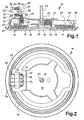
- FIG. 1 The cross-sectional view in Fig. 1 of an inventive Electric hotplate 11, which is on its actual top 12 is shown lying, has a substantially flat Hotplate body 13 on the inside with a centric ribs 14 is provided.
- a centric ribs 14 In the gaps between the ribs 14 are elongated tubular heaters 15 arranged with one in the left part of FIG. 1 shown short upward connecting line 16.
- the Hotplate body 13 To the outermost heating device 15 is the Hotplate body 13 is provided with an insert flange 17.
- a rim 20 which has a recess in an electric cooker in which the hotplate 11 is inserted is completed upwards.
- the Top 12 has a central indentation 18 which in one protruding thread approach 19 passes on the inside.
- the underside of the electric hotplate 11 is largely from a plate plate 21 covered, the middle of the threaded approach 19 rests and in its outer area to the outermost Heaters 15 and the insert flange 17 is applied.
- a threaded bolt screwed into the threaded shoulder 19 22 and a mother 23 guided on it Sheet plate 21 attached to the underside.
- an insulating piece 26 Through a recess 25 in the outer area of the plate plate 21 is an insulating piece 26 out with a section protrudes with a reduced diameter over the sheet, which rests on a substantially circumferential paragraph 27.
- a connecting wire 29 is guided through a bore 28, which is connected to the connecting line 16.
- the Bore 28 is in the lower area for simplified implementation of the lead wire 29 expanded.
- the Insulating piece 26 is a fit in the recess 25 supported, a kind of thread approach would also be possible.
- a plug-in tab 35 In a slot 34 in the connector 31 is a plug-in tab 35, of which a contact section 36 slightly beveled and tapered radially outwards and one Welding lug 37 is located radially inward, to which the connecting wire 29 is guided and connected.
- S is in plug direction the plug-in tab 35 by paragraphs in the upper and lower Area on corresponding shoulders 39 in the connector 31 held so that it occurs when a plug occurs Force in direction S can not be pressed further can.
- the plug-in lug 35 held by a tab 40 through the Slot 34 is guided and after insertion in a Opening 44 is rotated about its longitudinal direction, causing it extends over the boundary of the slot and thus one Pulling out prevented.
- the attachment of the plug connection lugs in the insulating piece is detailed in Figs. 8-10 shown and will be described later.
- connection between the welding lug 37 and the connecting wire 29 after inserting the with the connector lug 35 provided connector 31 by means of the detent 32nd is produced in the sheet metal plate, prevents this Movement in the opposite direction and thus a release of the Fitting.
- the electrical connection second function a mechanical connection.
- a temperature limiter 41 is attached, specifically in the area of the recess 18. This is limited the maximum achievable working temperature of the electric hotplate 11 and is sufficient for this purpose with at least one Measuring tip 42 on the hotplate body 13.
- FIG. 2 shows a view of the underside of the electric hotplate 11.
- Insulating piece 26 which is elongated with semicircular ends is formed and in the recess 25 in the plate plate 21 sits.
- the connecting wires are through four bores 28 29 out.
- the connecting piece borders on the insulating piece 31, which has four plug-in connection lugs 35 which with the contact section 36 radially outwards and with the Protruding welding tabs 37 inwards.
- Fig. 1 it can clearly be seen that neither the connecting piece 31 nor the connecting lugs 35 over the insert flange 17 of the hotplate body 13 survive.
- FIG. 3 is an enlarged view corresponding to FIG. 1 the area of the electric hotplate 11 shown in which is the connector 31.
- the connector is designed such that it is with a short detent 32 by a Detent opening 33 is guided in the plate plate 21 and the connector, that with a lower, radially inner Section on the radially outer part of the insulating piece 26 is present.
- the insulating piece 26 and its attachment and attachment to the electric hotplate 11 by means of of the plate plate 21 correspond to FIG. 1.
- plug-in terminal lugs 35 used, whereby, unlike in Fig. 1, upwards and essentially not to the side be covered by the connector. While in Fig. 1 the Tabs 40 are guided radially inwards, the tabs sit 40 here in a direction perpendicular to the insertion direction S. Opening 44. Similar to Fig. 1, the tabs in the Opening 44 through a corresponding to their material thickness Be guided slot, the protruding beyond this slot Part by twisting the entire plug connection lug 35 specifies. In the embodiment shown in Fig. 3 is the plug connection lug both in the plug direction S and in opposite direction only through the tab 40 and the connection of the welding lug 37 to the connecting wire 29 supported. Through this connection as well as through the plant the insulating piece 26 is a tipping out of the connector 31 prevented.
- Plug housing 45 led to the plug-in tabs 35th has corresponding plug-in connection shoes 46.
- the Plug-in connection shoes 46 can start from a flat side 55 have inwardly narrow tongues 56 in a narrow radius, the an inserted contact section against the Press flat page 55 for large-area contact.
- On the other end are the plug-in connection shoes with a flexible connecting line 47 connected.
- the contact section 36 has a hole 57 into which a not shown Projection on the flat side 55 of the plug connection shoe 46 intervene and a locking connection can manufacture.
- the plug housing 45 encompasses the plug connection shoes 46 full, which are laid down in it. This means that between the Plug-in connection shoes material bridges, which in one version of the connector 31 shown in FIG. 3 between each Plug connections are located and ensure insulation. For increased connection security are both on the connector 31 and on the connector housing coding lugs 48 provided that twisting or confusing the connector prevent it either mechanically or visually.
- Fig. 4 it can be seen that the connector tabs 35 in the Expose slots 34 upwards. Only by pushing it over of the connector housing 45 they are from this at least partially covered. As can be seen in Fig. 4, are the coding lugs 48 on connector 31 and Connector 45 when the connector is twisted, it is not possible to plug it on. In a similar way for an electric cooker or the like a number of connectors and connectors are provided with coding lugs such that both a twisting of the plug as well as a connection of a plug to an unintended hotplate is impossible.
- FIG. 4 shows the opening 44, in which the tab 40 compared to that in a plane with the Plug-in lug extending insertion slot 34 by about 60 ° is twisted, so that pulling out the tab and thus Remove the connector tab from the connector 31 is prevented.
- FIG. 5 corresponds to the structure of the hotplate 11 of FIG. 3. However, here is in the recess 25, through which Insulating piece 26 protrudes through the sheet metal plate 21 by lateral Bead a thin carrier 50 with the tin plate connected.
- the upper section of the insulating piece 26 extends through a carrier opening 51 which is inside the recess 25 runs beyond the tin plate.
- a gradation closes radially outward from the carrier opening 51 continuously a support section spaced from the metal plate 52 on.
- the connector 31 is attached to it, preferably similar to the previous versions by insertion a molded catch or the like. in a matching one Recess in the carrier section 52.
- the plug connection lugs 35 are essentially as in FIG. 1 designed, in the extension of the contact section 36th the tab 40 in an opening provided for fastening 44 stuck, twisted in it, and further the sweat 37 led to the lead wire 29 and with this is welded.
- shoulders 39 in the connector the plug-in tab 35 in the plug-in direction S and through the Tab 40 held in the opposite direction.
- the connector housing is similar to that in FIG. 3, however with a distinctly protruding coding lug 48.
- FIG. 6 shows a possible embodiment of a connector housing 45, which corresponds approximately to that of FIG. 5.
- the Coding nose is approximately triangular here with in the direction of insertion S running flattened tip 53 executed in a corresponding recess on the connector 31st can intervene.
- the coding lug 48 is slightly on the side Staggered in the middle of the plug, creating several plug connections can be marked.
- FIG. 7 shows a view of the inside similar to FIG. 4 5. You can see the carrier 50, which surrounds the insulating piece 26 and the connecting piece 31st wearing. At its radially inner end are the twisted ones Mounting tabs 40 out of the connector.
- the Plug housing 45 is essentially in this embodiment separate housing sections for the Plug-in connection shoes 46, one of which is an elongated, narrow coding nose 48 carries.
- Fig. 8 shows an enlarged section through a connector 35 according to FIG. 1. This can be clearly seen Rise of the contact surfaces 58 through the oblique line of the Delimitation of the opening 44 towards the slot 34.
- the direction of rotation V is seen from the welding lug 37 in Clockwise, the angle of rotation is about 30 °.
- the underside 61 of the connector 31 has arches 59, through which the contact surface towards the tin plate in order to reduce Heat retention is reduced. Are on top further coding recesses 60 are provided.
- FIG. 9 shows the connecting piece 31 from FIG. 8 from behind.
- a coding recess 49 can be seen, into which a coding lug 48 of the connector 45 can engage.
- the angle of rotation of the Tab 40 is approximately 30 ° clockwise.
- the openings 44 are round.
- the plug-in tabs 35 are except for the contact section 36 and sweat tab 37 completely from the connector surround.
- the number of coding pits is 60 depending on the plug-in lug over which they are formed, different and ranges from one to four.
- the latch 32 is in the middle of the connector on the through the arches 59 interrupted underside 61 formed. Through arches 59 the surface of the underside is cut in half, another Reduction is possible with a suitable choice of material.
- the partial section in Fig. 10 illustrates the increase in Contact surface 58 of the tab 40.
- a bending of the to Contact surfaces 58 adjacent tab edges against the Direction of rotation V occur and as self-locking of the rotation reach into the material of the contact surface by turning back to complicate and so the connection against unwanted Securing to secure.
- connection is first the plug-in tab 35 in the Inserted connector 31 and by rotating the tab 40 secured.
- the connector is then with a Latch 32 in a corresponding recess in the the hotplate body 13 attached plate 21, which Has insulating piece 26 in the recess 25 is used.
- the plug connection lug 35 or the welding lug 37 With the connecting wire 29 which through the bore 28th of the insulating piece 26, the connector 31 is in its position.
- the connection must be dismantled solved between plug-in tab 35 and connecting wire 29 become. It is possible to form the insulating piece 26 in one piece to execute the connector 31 and during assembly to lead a connecting wire 29.
- connecting the plug-in connection lug with the connecting wire the last one Step in the attachment of the connector.
Landscapes
- Baking, Grill, Roasting (AREA)
- Cookers (AREA)
- Resistance Heating (AREA)
- Connector Housings Or Holding Contact Members (AREA)
Description
- Fig. 1
- einen Querschnitt durch eine erfindungsgemäße Elektrokochplatte mit einem Anschlußstück, das Steckanschlußfahnen enthält und an einer Abdeckung der Kochplattenunterseite angebracht ist,
- Fig. 2
- eine Ansicht der Kochplatte aus Fig. 1 von unten,
- Fig. 3
- eine Variante eines Anschlußstücks samt Stekkergehäuse in einer vergrößerten Ansicht gemäß Fig. 1,
- Fig. 4
- eine Unteransicht der Elektrokochplatte aus Fig. 3,
- Fig. 5
- eine weitere Variante gemäß einem Aspekt der Erfindung mit einem an einem Träger angebrachtes Anschlußstück samt Steckergehäuse,
- Fig. 6
- eine Draufsicht auf ein erfindungsgemäßes Steckergehäuse, das im wesentlichen geschlossen ist sowie eine Codiernase aufweist,
- Fig. 7
- eine Ansicht der Elektrokochplatte aus Fig. 5 von unten,
- Fig. 8
- einen vergrößerten Querschnitt des Anschlußstücks aus Fig. 1,
- Fig. 9
- eine vergrößerte Rückansicht des Anschlußstücks aus Fig. 8 und
- Fig. 10
- eine Draufsicht auf das Anschlußstück aus Fig. 8 samt Teilschnitt mit Ansicht der verdrehten Befestigungslasche.
Claims (14)
- Verwendung einer Elektrokochplatte in einem Elektroherd mit mehreren Elektrokochplatten (11) mit einem Kochplattenkörper, einem unteren Abdeckblech und einem Anschlußstück zum elektrischen Anschluß der Kochplatte, wobei das Anschlußstück an dem Kochplattenkörper bzw. dem Abdeckblech angebracht ist, wobei das Anschlußstück (31) wenigstens eine Steckanschlußfahne (35) zur Kontaktierung von Steckanschlüssen aufweist, und daß die wenigstens eine Steckanschlußfahne einen Anschlußabschnitt zum Anschluß einer aus einer Unterseite der Kochplatte herausgeführten Anschlußleitung (16, 29) zur Energieversorgung der Elektrokochplatte (11) aufweist, dadurch gekennzeichnet, daß das Anschlußstück (31) abschnittsweise unterschiedlich ausgebildet ist jeweils im Bereich einer Steckanschlußfahne (35), wobei als Unterschiede Ausnehmungen und/oder Vorsprünge vorgesehen sind, die zu korrespondierenden Ausnehmungen und/oder Vorsprüngen in Steckergehäusen (45) der Steckanschlüsse passen.
- Verwendung einer Elektrokochplatte nach Anspruch 1, dadurch gekennzeichnet, daß das Anschlußstück (31) mit Arretierungsmittteln an der Unterseite des Kochplattenkörpers (13) bzw. des Abdeckblechs angebracht ist, insbesondere formschlüssig, wobei es vorzugsweise lösbar angebracht ist und die Arretierungsmittel insbesondere abstehende Rastnasen (32) sind, die durch Einschwenken in eine Ausnehmung in dem Kochplattenkörper oder dem Abdeckblech einführbar sind.
- Verwendung einer Elektrokochplatte nach Anspruch 1 oder 2, dadurch gekennzeichnet, daß das Anschlußstück (31) mit einem Isolierstück (26) verbunden ist, insbesondere einstückig, das wenigstens eine Anschlußleitung (16, 29) aufnimmt und durch das Abdeckblech geführt ist, wobei vorzugsweise Heizeinrichtungen (15) mit ihrer Anschlußleitung (16) über einen Anschlußdraht (29) mit den Steckanschlußfahnen (35) verbunden sind.
- Verwendung einer Elektrokochplatte nach einem der vorhergehenden Ansprüche, dadurch gekennzeichnet, daß die Anschlußleitungen (16, 29) mit den Steckanschlußfahnen (35) untrennbar verbunden und vorzugsweise miteinander verschweißt sind, wobei vorzugsweise die Verbindung der Anschlußleitungen mit den Steckanschlußfahnen eine zusätzliche Befestigung der Arretierungsmittel oder des Anschlußstücks (31) bildet.
- Verwendung einer Elektrokochplatte nach einem der vorhergehenden Ansprüche, dadurch gekennzeichnet, daß die Ausnehmungen und/oder Vorsprünge beim Einbau in den Elektroherd bei allen Kochplatten unterschiedlich sind.
- Verwendung einer Elektrokochplatte nach einem der vorhergehenden Ansprüche, dadurch gekennzeichnet, daß das Anschlußstück zwischen den Steckanschlußfahnen (35) Materialbrücken o.dgl. aufweist, die die Steckanschlußfahnen abstützen und insbesondere eine direkte Luftverbindung blockieren, und insbesondere an seiner Unterseite (61) Ausnehmungen in Form von Bögen (59) o.dgl. aufweist zur Reduzierung der Kontaktfläche zwischen Anschlußstück (31) und Kochplatte.
- Verwendung einer Elektrokochplatte nach einem der vorhergehenden Ansprüche, dadurch gekennzeichnet, daß das Anschlußstück (31) an einem Träger (50) an dem Kochplattenkörper (13) bzw. dem unteren Abdeckblech angebracht ist, der insbesondere durch Umbördeln oder Verstemmen befestigt ist, wobei der Träger vorzugsweise wärmebeständig und/oder isolierend ausgebildet ist und insbesondere das Isolierstück (26) zumindest teilweise umgibt.
- Verwendung einer Elektrokochplatte nach einem der vorhergehenden Ansprüche, dadurch gekennzeichnet, daß das Anschlußstück (31) und/oder die Steckanschlußfahnen (35) nicht über den Außenradius des Kochplattenkörpers (13) überstehen und vorzugsweise radial innerhalb eines in eine Ausnehmung eines Elektroherdes einzuführenden Randes, insbesondere eines flanschartig abstehenden Randes, des Kochplattenkörpers verlaufen.
- Verwendung einer Elektrokochplatte nach einem der vorhergehenden Ansprüche, dadurch gekennzeichnet, daß wenigstens eine Steckanschlußfahne (35), insbesondere in einer Steckrichtung (S), mit Absätzen o.dgl. in dem Anschlußstück (31) abgestützt ist, wobei sie vorzugsweise von einer seite aus in das Anschlußstück einführbar ist, insbesondere in Steckrichtung.
- Verwendung einer Elektrokochplatte nach einem der vorhergehenden Ansprüche, dadurch gekennzeichnet, daß wenigstens eine Steckanschlußfahne (35) mit Verriegelungsmitteln an dem Anschlußstück (31) angebracht ist, insbesondere formschlüssig, wobei vorzugsweise an der Steckanschlußfahne eine Lasche (40) als Verriegelungsmittel angeformt ist, die zur Befestigung an dem Anschlußstück in eine Ausnehmung (44) eingreift und verformbar oder verdrehbar ist.
- Verwendung einer Elektrokochplatte nach einem der vorhergehenden Ansprüche, dadurch gekennzeichnet, daß wenigstens eine Steckanschlußfahne (35) aus dem Anschlußstück (31) hervorragt, bevorzugt mit einem gesamten durch einen Steckanschluß zu kontaktierenden Kontaktabschnitt (36), wobei insbesondere ein Teil der Steckanschlußfahne vollständig von dem Anschlußstück umgeben ist.
- Verwendung einer Elektrokochplatte nach einem der vorhergehenden Ansprüche, dadurch gekennzeichnet, daß das Abdeckblech als ein diese zumindest teilweise umschließender Blechteller (21) ausgebildet ist, der im wesentlichen geschlossen ist und die Unterseite des Kochplattenkörpers (13) abdeckt, wobei Durchführungen für Anschlußdrähte (29) und mindestens ein, insbesondere zentral angeordnetes, Befestigungselement zur Befestigung an einem Elektroherd vorgesehen sind.
- Elektroherd mit mehreren Elektrokochplatten (11) mit einem Kochplattenkörper, einem unteren Abdeckblech und einem Anschlußstück zum elektrischen Anschluß der Kochplatte, wobei das Anschlußstück an dem Kochplattenkörper bzw. dem Abdeckblech angebracht ist, wobei das Anschlußstück (31) wenigstens eine Steckanschlußfahne (35) zur Kontaktierung von Steckanschlüssen aufweist, und daß die wenigstens eine Steckanschlußfahne einen Anschlußabschnitt zum Anschluß einer aus einer Unterseite der Kochplatte herausgeführten Anschlußleitung (16, 29) zur Energieversorgung der Elektrokochplatte (11) aufweist, dadurch gekennzeichnet, daß das Anschlußstück (31) abschnittsweise unterschiedlich ausgebildet ist jeweils im Bereich einer Steckanschlußfahne (35), wobei als Unterschiede Ausnehmungen und/oder Vorsprünge vorgesehen sind, die zu korrespondierenden Ausnehmungen und/oder Vorsprüngen in Steckergehäusen (45) der Steckanschlüsse passen.
- Elektroherd nach Anspruch 13, dadurch gekennzeichnet, daß die Elektrokochplatte (11) nach einem der Ansprüche 2 bis 12 ausgebildet ist.
Priority Applications (1)
| Application Number | Priority Date | Filing Date | Title |
|---|---|---|---|
| SI9930664T SI0957661T2 (sl) | 1998-05-12 | 1999-04-09 | Uporaba električne kuhalne plošče v električnem štedilniku in električni štedilnik |
Applications Claiming Priority (2)
| Application Number | Priority Date | Filing Date | Title |
|---|---|---|---|
| DE1998121140 DE19821140B4 (de) | 1998-05-12 | 1998-05-12 | Elektrokochplatte |
| DE19821140 | 1998-05-12 |
Publications (4)
| Publication Number | Publication Date |
|---|---|
| EP0957661A2 EP0957661A2 (de) | 1999-11-17 |
| EP0957661A3 EP0957661A3 (de) | 2000-09-06 |
| EP0957661B1 true EP0957661B1 (de) | 2004-06-30 |
| EP0957661B2 EP0957661B2 (de) | 2014-10-15 |
Family
ID=7867460
Family Applications (1)
| Application Number | Title | Priority Date | Filing Date |
|---|---|---|---|
| EP99106973.3A Expired - Lifetime EP0957661B2 (de) | 1998-05-12 | 1999-04-09 | Verwendung einer Elektrokochplatte in einem Elektroherd und Elektroherd |
Country Status (5)
| Country | Link |
|---|---|
| EP (1) | EP0957661B2 (de) |
| DE (3) | DE19821140B4 (de) |
| ES (1) | ES2224481T5 (de) |
| SI (1) | SI0957661T2 (de) |
| TR (1) | TR199901031A3 (de) |
Families Citing this family (9)
| Publication number | Priority date | Publication date | Assignee | Title |
|---|---|---|---|---|
| DE19942964A1 (de) * | 1999-09-09 | 2001-03-15 | Ego Elektro Geraetebau Gmbh | Elektrisches Schaltgerät |
| IL164989A0 (en) * | 2004-11-02 | 2005-12-18 | Moshe Neger | A food warming tray |
| DE102007017456A1 (de) | 2007-04-04 | 2008-10-09 | E.G.O. Elektro-Gerätebau GmbH | Anschlussvorrichtung für eine Elektrokochplatte und Elektrokochplatte |
| TR201008981A2 (tr) | 2010-11-01 | 2011-09-21 | Tura� Gaz Armat�Rler� San. Ve T�C. A.�. | Evsel pişirici cihazlar için hibrid yakici |
| DE102011051017A1 (de) * | 2011-06-10 | 2012-12-13 | Eichenauer Heizelemente Gmbh & Co. Kg | Elektrische Heizeinrichtung |
| EP3206459B1 (de) | 2016-02-10 | 2019-04-03 | E.G.O. ELEKTRO-GERÄTEBAU GmbH | Kochplatte und kochfeld mit einer kochplatte |
| EP3479440B1 (de) | 2016-07-01 | 2020-02-12 | Arçelik Anonim Sirketi | Elektrisches anschlussgerät zur verwendung im backofen |
| DE102017211100A1 (de) * | 2017-06-29 | 2019-01-03 | E.G.O. Elektro-Gerätebau GmbH | Kochplatte |
| DE102017211812A1 (de) | 2017-07-11 | 2019-01-17 | E.G.O. Elektro-Gerätebau GmbH | Kochplattenvorrichtung mit einer Kochplatte und Kochfeld |
Family Cites Families (13)
| Publication number | Priority date | Publication date | Assignee | Title |
|---|---|---|---|---|
| DE2442717A1 (de) * | 1974-09-06 | 1976-03-18 | Karl Fischer | Elektrische heizplatte fuer elektroherde |
| DE2620004C3 (de) | 1976-05-06 | 1979-05-31 | Fischer, Karl, 7519 Oberderdingen | Elektrokochplatte mit einem Temperaturbegrenzer |
| US4376565A (en) † | 1981-02-17 | 1983-03-15 | Amp Incorporated | Electrical connector keying means |
| DE3131462A1 (de) * | 1981-08-08 | 1983-02-24 | Karl 7519 Oberderdingen Fischer | Temperaturbegrenzte kochplatte |
| DE3301219A1 (de) † | 1983-01-15 | 1984-07-19 | E.G.O. Elektro-Geräte Blanc u. Fischer, 7519 Oberderdingen | Elektrokochplatte |
| US5166995A (en) † | 1984-06-08 | 1992-11-24 | Amp Incorporated | Polarized connector |
| DE3540815A1 (de) † | 1985-11-16 | 1987-05-27 | Ego Elektro Blanc & Fischer | Elektrokochplatte sowie vorrichtung fuer deren anschluss |
| DE3728535A1 (de) * | 1987-08-27 | 1989-03-09 | Ego Elektro Blanc & Fischer | Herdplatte |
| DE3803806A1 (de) | 1988-02-09 | 1989-08-17 | Ego Elektro Blanc & Fischer | Elektrokochplatte |
| US4993553A (en) * | 1988-02-09 | 1991-02-19 | E.G.O. Elektro Gerate Blanc U. Fischer | Electric hotplate stacking aid |
| DE4008830A1 (de) * | 1990-03-20 | 1991-09-26 | Ego Elektro Blanc & Fischer | Elektrokochplatte |
| DE4028362A1 (de) * | 1990-09-06 | 1992-03-12 | Ego Elektro Blanc & Fischer | Elektrokochgeraet mit einer elektrokochplatte |
| ES1038983Y (es) | 1997-12-09 | 1999-03-01 | Eika S Coop | Conector aislante para los cables de alimentacion de una placa de coc ina electrica. |
-
1998
- 1998-05-12 DE DE1998121140 patent/DE19821140B4/de not_active Expired - Lifetime
-
1999
- 1999-04-09 EP EP99106973.3A patent/EP0957661B2/de not_active Expired - Lifetime
- 1999-04-09 ES ES99106973.3T patent/ES2224481T5/es not_active Expired - Lifetime
- 1999-04-09 DE DE29924784U patent/DE29924784U1/de not_active Expired - Lifetime
- 1999-04-09 SI SI9930664T patent/SI0957661T2/sl unknown
- 1999-04-09 DE DE59909836T patent/DE59909836D1/de not_active Expired - Lifetime
- 1999-05-11 TR TR1999/01031A patent/TR199901031A3/tr unknown
Also Published As
| Publication number | Publication date |
|---|---|
| HK1023683A1 (en) | 2000-09-15 |
| TR199901031A2 (xx) | 1999-12-21 |
| SI0957661T2 (sl) | 2015-01-30 |
| DE59909836D1 (de) | 2004-08-05 |
| TR199901031A3 (tr) | 1999-12-21 |
| EP0957661A2 (de) | 1999-11-17 |
| DE19821140B4 (de) | 2009-08-27 |
| SI0957661T1 (en) | 2004-12-31 |
| DE29924784U1 (de) | 2005-08-11 |
| ES2224481T3 (es) | 2005-03-01 |
| ES2224481T5 (es) | 2015-01-07 |
| EP0957661B2 (de) | 2014-10-15 |
| DE19821140A1 (de) | 1999-11-18 |
| EP0957661A3 (de) | 2000-09-06 |
Similar Documents
| Publication | Publication Date | Title |
|---|---|---|
| EP0070043B1 (de) | Elektrokochplatte | |
| DE102020208149A1 (de) | Modulverbinder | |
| EP2962366B1 (de) | Elektrischer industriesteckverbinder | |
| EP2446509B1 (de) | Elektrischer steckverbinder | |
| EP3079442B1 (de) | Elektrische heizvorrichtung und rahmen hierfür | |
| EP1916740B1 (de) | Installationsschaltgerät und Anschlussklemme für ein Installationsschaltgerät | |
| DE2810402A1 (de) | Lampen-sockel-aufbau | |
| CH664855A5 (de) | Anordnung zum verbinden der drahtenden einer statorwicklung eines elektromotors mit einer anschlussleitung. | |
| EP3613110B1 (de) | Baugruppe für ein steckverbinderteil mit einem kontakteinsatz und einem erdungselement | |
| DE102017104982B3 (de) | Elektrischer Stecker mit spezifischer Erdung von Außenteilen | |
| EP0957661B2 (de) | Verwendung einer Elektrokochplatte in einem Elektroherd und Elektroherd | |
| EP0113923B1 (de) | Elektrokochplatte | |
| EP0307629B1 (de) | Elektro-Kochplatte | |
| DE2913542A1 (de) | Backofenlampe fuer haushaltbackoefen | |
| EP0307630A1 (de) | Herdplatte | |
| DE69406376T2 (de) | Elektrische Verbindungsvorrichtung, insbesondere für Hochstromdurchgang | |
| EP0327849A2 (de) | Elektrokochplatte | |
| EP0258590B1 (de) | Durchführungsstück zum Hindurchführen von Anschlussleitungen für eine Elektro-Kochplatte | |
| DE2933349A1 (de) | Elektrokochplatte | |
| EP3830910B1 (de) | Steckvorrichtung mit verrastbaren komponenten | |
| DE69100075T2 (de) | Zigarettenanzuenderkoerper, insbesondere fuer kraftfahrzeuge und der aufbau eines leuchtenden anzuenderkoerperringes mit einem solchen anzuenderkoerper. | |
| EP0442284B1 (de) | Elektrokochplatte | |
| EP0447859A2 (de) | Elektrokochplatte | |
| EP1709842B1 (de) | Vorschaltgerätekasten | |
| DE202019005220U1 (de) | Elektrische Heizvorrichtung |
Legal Events
| Date | Code | Title | Description |
|---|---|---|---|
| PUAI | Public reference made under article 153(3) epc to a published international application that has entered the european phase |
Free format text: ORIGINAL CODE: 0009012 |
|
| AK | Designated contracting states |
Kind code of ref document: A2 Designated state(s): DE DK ES FI FR GB GR IT SE |
|
| AX | Request for extension of the european patent |
Free format text: AL;LT;LV;MK;RO;SI |
|
| PUAL | Search report despatched |
Free format text: ORIGINAL CODE: 0009013 |
|
| AK | Designated contracting states |
Kind code of ref document: A3 Designated state(s): AT BE CH CY DE DK ES FI FR GB GR IE IT LI LU MC NL PT SE |
|
| AX | Request for extension of the european patent |
Free format text: AL;LT;LV;MK;RO;SI |
|
| TPAD | Observations filed by third parties |
Free format text: ORIGINAL CODE: EPIDOS TIPA |
|
| 17P | Request for examination filed |
Effective date: 20010210 |
|
| AKX | Designation fees paid |
Free format text: DE DK ES FI FR GB GR IT SE |
|
| AXX | Extension fees paid |
Free format text: SI PAYMENT 20010210 |
|
| 17Q | First examination report despatched |
Effective date: 20030404 |
|
| RTI1 | Title (correction) |
Free format text: USE OF AN ELECTRIC COOKING PLATE IN AN ELECTRIC RANGE AND ELECTRIC RANGE |
|
| GRAP | Despatch of communication of intention to grant a patent |
Free format text: ORIGINAL CODE: EPIDOSNIGR1 |
|
| GRAS | Grant fee paid |
Free format text: ORIGINAL CODE: EPIDOSNIGR3 |
|
| GRAA | (expected) grant |
Free format text: ORIGINAL CODE: 0009210 |
|
| AK | Designated contracting states |
Kind code of ref document: B1 Designated state(s): DE DK ES FI FR GB GR IT SE |
|
| AX | Request for extension of the european patent |
Extension state: SI |
|
| PG25 | Lapsed in a contracting state [announced via postgrant information from national office to epo] |
Ref country code: GB Free format text: LAPSE BECAUSE OF FAILURE TO SUBMIT A TRANSLATION OF THE DESCRIPTION OR TO PAY THE FEE WITHIN THE PRESCRIBED TIME-LIMIT Effective date: 20040630 Ref country code: FR Free format text: LAPSE BECAUSE OF FAILURE TO SUBMIT A TRANSLATION OF THE DESCRIPTION OR TO PAY THE FEE WITHIN THE PRESCRIBED TIME-LIMIT Effective date: 20040630 Ref country code: FI Free format text: LAPSE BECAUSE OF FAILURE TO SUBMIT A TRANSLATION OF THE DESCRIPTION OR TO PAY THE FEE WITHIN THE PRESCRIBED TIME-LIMIT Effective date: 20040630 |
|
| REG | Reference to a national code |
Ref country code: GB Ref legal event code: FG4D Free format text: NOT ENGLISH |
|
| REF | Corresponds to: |
Ref document number: 59909836 Country of ref document: DE Date of ref document: 20040805 Kind code of ref document: P |
|
| REG | Reference to a national code |
Ref country code: SE Ref legal event code: TRGR |
|
| PG25 | Lapsed in a contracting state [announced via postgrant information from national office to epo] |
Ref country code: GR Free format text: LAPSE BECAUSE OF FAILURE TO SUBMIT A TRANSLATION OF THE DESCRIPTION OR TO PAY THE FEE WITHIN THE PRESCRIBED TIME-LIMIT Effective date: 20040930 Ref country code: DK Free format text: LAPSE BECAUSE OF FAILURE TO SUBMIT A TRANSLATION OF THE DESCRIPTION OR TO PAY THE FEE WITHIN THE PRESCRIBED TIME-LIMIT Effective date: 20040930 |
|
| GBV | Gb: ep patent (uk) treated as always having been void in accordance with gb section 77(7)/1977 [no translation filed] |
Effective date: 20040630 |
|
| REG | Reference to a national code |
Ref country code: SI Ref legal event code: IF |
|
| REG | Reference to a national code |
Ref country code: HK Ref legal event code: GR Ref document number: 1023683 Country of ref document: HK |
|
| REG | Reference to a national code |
Ref country code: ES Ref legal event code: FG2A Ref document number: 2224481 Country of ref document: ES Kind code of ref document: T3 |
|
| PLAQ | Examination of admissibility of opposition: information related to despatch of communication + time limit deleted |
Free format text: ORIGINAL CODE: EPIDOSDOPE2 |
|
| PLBQ | Unpublished change to opponent data |
Free format text: ORIGINAL CODE: EPIDOS OPPO |
|
| PLBI | Opposition filed |
Free format text: ORIGINAL CODE: 0009260 |
|
| PLAB | Opposition data, opponent's data or that of the opponent's representative modified |
Free format text: ORIGINAL CODE: 0009299OPPO |
|
| PLAQ | Examination of admissibility of opposition: information related to despatch of communication + time limit deleted |
Free format text: ORIGINAL CODE: EPIDOSDOPE2 |
|
| PLAR | Examination of admissibility of opposition: information related to receipt of reply deleted |
Free format text: ORIGINAL CODE: EPIDOSDOPE4 |
|
| PLBQ | Unpublished change to opponent data |
Free format text: ORIGINAL CODE: EPIDOS OPPO |
|
| PLAX | Notice of opposition and request to file observation + time limit sent |
Free format text: ORIGINAL CODE: EPIDOSNOBS2 |
|
| 26 | Opposition filed |
Opponent name: EIKA, S. COOP. Effective date: 20050318 |
|
| R26 | Opposition filed (corrected) |
Opponent name: EIKA, S. COOP. Effective date: 20050318 |
|
| EN | Fr: translation not filed | ||
| PLBB | Reply of patent proprietor to notice(s) of opposition received |
Free format text: ORIGINAL CODE: EPIDOSNOBS3 |
|
| PLAB | Opposition data, opponent's data or that of the opponent's representative modified |
Free format text: ORIGINAL CODE: 0009299OPPO |
|
| R26 | Opposition filed (corrected) |
Opponent name: EIKA, S. COOP. Effective date: 20050318 |
|
| APBP | Date of receipt of notice of appeal recorded |
Free format text: ORIGINAL CODE: EPIDOSNNOA2O |
|
| APAH | Appeal reference modified |
Free format text: ORIGINAL CODE: EPIDOSCREFNO |
|
| APBQ | Date of receipt of statement of grounds of appeal recorded |
Free format text: ORIGINAL CODE: EPIDOSNNOA3O |
|
| APAH | Appeal reference modified |
Free format text: ORIGINAL CODE: EPIDOSCREFNO |
|
| APBU | Appeal procedure closed |
Free format text: ORIGINAL CODE: EPIDOSNNOA9O |
|
| PUAH | Patent maintained in amended form |
Free format text: ORIGINAL CODE: 0009272 |
|
| STAA | Information on the status of an ep patent application or granted ep patent |
Free format text: STATUS: PATENT MAINTAINED AS AMENDED |
|
| 27A | Patent maintained in amended form |
Effective date: 20141015 |
|
| AK | Designated contracting states |
Kind code of ref document: B2 Designated state(s): DE DK ES FI FR GB GR IT SE |
|
| AX | Request for extension of the european patent |
Extension state: SI |
|
| REG | Reference to a national code |
Ref country code: DE Ref legal event code: R102 Ref document number: 59909836 Country of ref document: DE |
|
| REG | Reference to a national code |
Ref country code: DE Ref legal event code: R102 Ref document number: 59909836 Country of ref document: DE Effective date: 20141015 |
|
| REG | Reference to a national code |
Ref country code: SE Ref legal event code: RPEO |
|
| REG | Reference to a national code |
Ref country code: ES Ref legal event code: DC2A Ref document number: 2224481 Country of ref document: ES Kind code of ref document: T5 Effective date: 20150107 |
|
| REG | Reference to a national code |
Ref country code: HK Ref legal event code: AM43 Ref document number: 1023683 Country of ref document: HK |
|
| PGFP | Annual fee paid to national office [announced via postgrant information from national office to epo] |
Ref country code: ES Payment date: 20180523 Year of fee payment: 20 Ref country code: DE Payment date: 20180419 Year of fee payment: 20 |
|
| PGFP | Annual fee paid to national office [announced via postgrant information from national office to epo] |
Ref country code: IT Payment date: 20180420 Year of fee payment: 20 |
|
| PGFP | Annual fee paid to national office [announced via postgrant information from national office to epo] |
Ref country code: SE Payment date: 20180424 Year of fee payment: 20 |
|
| REG | Reference to a national code |
Ref country code: DE Ref legal event code: R071 Ref document number: 59909836 Country of ref document: DE |
|
| REG | Reference to a national code |
Ref country code: SE Ref legal event code: EUG |
|
| REG | Reference to a national code |
Ref country code: ES Ref legal event code: FD2A Effective date: 20200723 |
|
| PG25 | Lapsed in a contracting state [announced via postgrant information from national office to epo] |
Ref country code: ES Free format text: LAPSE BECAUSE OF EXPIRATION OF PROTECTION Effective date: 20190410 |