EP0951131B1 - Elektrische Antriebseinheit aus Elektromotor und Elektronikmodul - Google Patents
Elektrische Antriebseinheit aus Elektromotor und Elektronikmodul Download PDFInfo
- Publication number
- EP0951131B1 EP0951131B1 EP99106967A EP99106967A EP0951131B1 EP 0951131 B1 EP0951131 B1 EP 0951131B1 EP 99106967 A EP99106967 A EP 99106967A EP 99106967 A EP99106967 A EP 99106967A EP 0951131 B1 EP0951131 B1 EP 0951131B1
- Authority
- EP
- European Patent Office
- Prior art keywords
- drive unit
- unit
- electric drive
- electric
- electric motor
- Prior art date
- Legal status (The legal status is an assumption and is not a legal conclusion. Google has not performed a legal analysis and makes no representation as to the accuracy of the status listed.)
- Expired - Lifetime
Links
Images

Classifications
-
- F—MECHANICAL ENGINEERING; LIGHTING; HEATING; WEAPONS; BLASTING
- F04—POSITIVE - DISPLACEMENT MACHINES FOR LIQUIDS; PUMPS FOR LIQUIDS OR ELASTIC FLUIDS
- F04D—NON-POSITIVE-DISPLACEMENT PUMPS
- F04D25/00—Pumping installations or systems
- F04D25/02—Units comprising pumps and their driving means
- F04D25/06—Units comprising pumps and their driving means the pump being electrically driven
- F04D25/068—Mechanical details of the pump control unit
-
- H—ELECTRICITY
- H02—GENERATION; CONVERSION OR DISTRIBUTION OF ELECTRIC POWER
- H02K—DYNAMO-ELECTRIC MACHINES
- H02K11/00—Structural association of dynamo-electric machines with electric components or with devices for shielding, monitoring or protection
- H02K11/30—Structural association with control circuits or drive circuits
- H02K11/33—Drive circuits, e.g. power electronics
-
- H—ELECTRICITY
- H02—GENERATION; CONVERSION OR DISTRIBUTION OF ELECTRIC POWER
- H02K—DYNAMO-ELECTRIC MACHINES
- H02K5/00—Casings; Enclosures; Supports
- H02K5/04—Casings or enclosures characterised by the shape, form or construction thereof
- H02K5/20—Casings or enclosures characterised by the shape, form or construction thereof with channels or ducts for flow of cooling medium
- H02K5/203—Casings or enclosures characterised by the shape, form or construction thereof with channels or ducts for flow of cooling medium specially adapted for liquids, e.g. cooling jackets
-
- H—ELECTRICITY
- H02—GENERATION; CONVERSION OR DISTRIBUTION OF ELECTRIC POWER
- H02K—DYNAMO-ELECTRIC MACHINES
- H02K5/00—Casings; Enclosures; Supports
- H02K5/04—Casings or enclosures characterised by the shape, form or construction thereof
- H02K5/22—Auxiliary parts of casings not covered by groups H02K5/06-H02K5/20, e.g. shaped to form connection boxes or terminal boxes
- H02K5/225—Terminal boxes or connection arrangements
-
- H—ELECTRICITY
- H05—ELECTRIC TECHNIQUES NOT OTHERWISE PROVIDED FOR
- H05K—PRINTED CIRCUITS; CASINGS OR CONSTRUCTIONAL DETAILS OF ELECTRIC APPARATUS; MANUFACTURE OF ASSEMBLAGES OF ELECTRICAL COMPONENTS
- H05K7/00—Constructional details common to different types of electric apparatus
- H05K7/20—Modifications to facilitate cooling, ventilating, or heating
- H05K7/2089—Modifications to facilitate cooling, ventilating, or heating for power electronics, e.g. for inverters for controlling motor
- H05K7/20927—Liquid coolant without phase change
-
- H—ELECTRICITY
- H02—GENERATION; CONVERSION OR DISTRIBUTION OF ELECTRIC POWER
- H02K—DYNAMO-ELECTRIC MACHINES
- H02K2211/00—Specific aspects not provided for in the other groups of this subclass relating to measuring or protective devices or electric components
- H02K2211/03—Machines characterised by circuit boards, e.g. pcb
Definitions
- Electric drive units are used in a variety of applications; For example, the use of low-emission motor vehicles, which relate at least part of the drive energy and / or the energy for auxiliary drives by electrical means, is increasingly being promoted in the motor vehicle sector.
- Electric drive units consist of an electric motor for generating and providing electrical drive power and an electronic module for controlling and monitoring the electric motor, for example for speed and power control of the electric motor.
- the electric motor must be cooled because of its high power density and is therefore equipped with a cooling circuit (usually this is a water cooling with water used as the coolant of the cooling circuit); in a double-walled electric motor housing, a water jacket provided for transporting the cooling water is arranged between the outer wall and the inner wall of the electric motor housing for this purpose.
- the electronic unit Spaced apart from the electric motor, the electronic unit comprising several functional units (in particular a power unit and a drive unit) is arranged as an independent unit, of which at least one functional unit usually has a high power loss and must be cooled accordingly - to dissipate this power loss (in particular to dissipate the power loss the power unit), the electronic module has its own cooling circuit, which is connected in series with the cooling circuit of the electric motor and connected thereto via connecting hoses. Between the electronic module and the electric motor external signal lines and supply lines are provided for forwarding sensor signals and control signals and for power supply; These connecting lines designed as cables are connected by means of connecting plugs to the plug connections of electronic module housing and electric motor housing provided for this purpose.
- the invention has for its object to provide an electric drive unit of electric motor and electronic module, on the other hand, has advantageous properties, in particular a simple structure and low cost, high reliability and simplified manufacturing.
- Electric motor and electronic module form an integrated electric drive unit, in particular, the cooling function for electric motor and electronic module is realized together (the cooling circuit is shared).
- the cooling circuit is shared in the electronics module housing for this purpose a recess for receiving a radiator insert and in the outer wall of the electric motor housing a corresponding recess is provided for this purpose; prior to joining the electric motor and electronic module, the radiator insert is inserted into the recess in the electronics module housing, when assembling the electric motor and electronic module, the radiator insert is (in particular flush) to the inner wall of the electric motor housing and is thus completely in the flowed through by the coolant cooling circuit (For example, in the water jacket) of the electric motor integrated - thereby the electric motor and electronic module (especially the power unit of the electronic module) are cooled simultaneously.
- the coolant cooling circuit For example, in the water jacket
- the radiator insert is thermally insulated from the inner wall of the electric motor housing by a thermal insulation layer applied to the underside of the radiator insert.
- This thermal insulation layer is bsp. realized by means of an applied to the underside of the radiator insert, high temperature resistant plastic film, bsp. by means of a single-sided adhesive polyimide film or Teflon film - Ex.
- the shape of the radiator insert is adapted to the shape of the electric motor and electronic module or to the housing shape of the electric motor housing and electronic module housing;
- the size of the radiator insert depends on the dissipated power loss, ie the required cooling function must be ensured by the radiator insert.
- the voltage applied to the inner wall of the electric motor housing underside of the radiator insert can be provided to increase the surface area and to specify "flow channels" for the coolant with geometric elements, eg. with rhombuses, truncated pyramids or lenses.
- the radiator insert is preferably made of a material with high thermal conductivity, eg. made of copper, die-cast aluminum, AlSiC or AlN.
- the mechanical connection between the electric motor and electronic module by means of suitable fasteners, eg. by means of screws fastened by means of screws.
- the electrical connection between the electric motor and the electronic module takes place by means of internal connection lines within the overall housing of the electric drive unit via recesses in the electric motor housing and electronic module housing (eg via recesses provided in the region of the end shield of the electric motor), so that no external plug connections and no external connection lines are required for this purpose.
- a plurality of functional units are integrated in a compact structure comprising several circuit levels: eg. in a first circuit level, a power unit with power semiconductor components for generating the clocked phase currents for the electric motor, in a second circuit level above the power unit arranged on a high-current circuit board connection unit with conductors and pads for phase busbar, DC supply and contacting and in another circuit level above the connection unit, a drive unit for controlling and monitoring the power semiconductor components of the power unit.
- circuit levels eg. in a first circuit level, a power unit with power semiconductor components for generating the clocked phase currents for the electric motor, in a second circuit level above the power unit arranged on a high-current circuit board connection unit with conductors and pads for phase busbar, DC supply and contacting and in another circuit level above the connection unit, a drive unit for controlling and monitoring the power semiconductor components of the power unit.
- connecting elements eg made of copper or copper alloys
- compensating beads for mechanical decoupling of the various Circuit levels provided.
- the cooler insert 4 is bsp. from provided with fillers Al diecasting and has bsp. the dimensions are 121 mm x 76 mm and a thickness of 10 mm.
- the radiator insert 4 As shown in FIG. 3, on the underside 41 of the radiator insert 4 as geometric elements 42 for enlarging the cooling surface or for specifying flow channels 43 for the cooling water 44, for example. Diamonds attached; The cooling water 44 must therefore flow in the flow channels 43 between the rhombuses 42, so that a good cooling effect is ensured by the radiator insert 4 due to forced convection.
- the radiator insert 4 with the power unit 31 applied directly thereto is inserted into a recess in the electronics module housing 34 adapted to the size of the radiator insert 4.
- the radiator insert 4 When joining the electric motor 2 and electronic module 3, the radiator insert 4 is positively inserted into a recess in the outer wall 22 of the electric motor housing 21 and placed flush with the geometry elements 42 (diamonds) on the inner wall 23 of the electric motor housing 21; hereby, the radiator insert 4 is integrated into the water jacket 24 of the electric motor 1 and the cooling of the electronic module 3 is coupled directly to the cooling of the electric motor 2.
- the sealing of the radiator insert 4 to the electric motor 2 out can bsp. be done by means of a molded seal 6, bsp. by means of a bsp.
- the molded seal 6 is introduced into a circumferential groove 45 on the border of the radiator insert 4 (see FIG. 3).
- the thermal decoupling of the radiator insert 4 and the inner wall 23 of the electric motor housing 21 is realized by means of a thermal insulation layer 7 applied to the underside 41 of the radiator insert 4 (on the geometric elements 42 of the radiator insert 4), eg. by a (eg glued) thermal insulation film 7; the thermal insulation film 7 is bsp. designed as a plastic film with relatively poor heat conduction, bsp. as one-sided adhesive plastic film made of polyester or Kapton.
- the electrical connection between the electric motor 2 and the electronic module 3 when assembling the electric motor 2 and the electronic module 3 takes place by means of internal connecting lines, which are passed through recesses in the electric motor housing 21 and electronic module housing 34; the recesses are bsp. in the area of the first bearing plate 26, as connecting lines are bsp. Phase ends provided.
- the mechanical fixing of the electric motor 2 and the electronic module 3 when assembling the electric motor 2 and the electronic module 3 takes place by screwing the electronics module housing 34 to the electric motor housing 21 by means of fastening elements 51 and screws 52, whereby a compact integrated electric drive unit 1 is formed.
Landscapes
- Engineering & Computer Science (AREA)
- Power Engineering (AREA)
- Microelectronics & Electronic Packaging (AREA)
- Physics & Mathematics (AREA)
- Thermal Sciences (AREA)
- Mechanical Engineering (AREA)
- General Engineering & Computer Science (AREA)
- Motor Or Generator Cooling System (AREA)
- Motor Or Generator Frames (AREA)
Description
- Elektrische Antriebseinheiten werden in vielfältigen Anwendungsgebieten eingesetzt; beispielsweise wird im Kfz-Bereich verstärkt der Gebrauch von emissionsarmen Kraftfahrzeugen propagiert, die zumindest einen Teil der Antriebsenergie und/oder der Energie für Hilfsantriebe auf elektrischem Wege beziehen. Elektrische Antriebseinheiten bestehen aus einem Elektromotor zur Erzeugung und Bereitstellung von elektrischer Antriebsleistung und aus einem Elektronikmodul zur Ansteuerung und überwachung des Elektromotors, beispielsweise zur Drehzahl- und Leistungsregelung des Elektromotors.
Der Elektromotor muß aufgrund seiner hohen Leistungsdichte gekühlt werden und ist daher mit einem Kühlkreislauf ausgestattet (meistens wird hierfür eine Wasserkühlung mit Wasser als Kühlmittel des Kühlkreislaufs verwendet); bei einem doppelwandigen Elektromotorgehäuse ist hierzu ein für den Transport des Kühlwassers vorgesehener Wassermantel zwischen der Außenwand und der Innenwand des Elektromotorgehäuses angeordnet. Beabstandet zum Elektromotor ist als eigenständige Einheit das mehrere Funktionseinheiten (insbesondere eine Leistungseinheit und eine Ansteuereinheit) umfassende Elektronikmodul angeordnet, von denen in der Regel mindestens eine Funktionseinheit eine hohe Verlustleistung aufweist und dementsprechend gekühlt werden muß - zum Abführen dieser Verlustleistung (insbesondere zum Abführen der Verlustleistung der Leistungseinheit) weist das Elektronikmodul einen eigenen Kühlkreislauf auf, der in Reihe zum Kühlkreislauf des Elektromotors geschaltet und mit diesem über Verbindungsschläuche verbunden ist. Zwischen dem Elektronikmodul und dem Elektromotor sind zur Weiterleitung von Sensorsignalen und Steuersignalen sowie zur Spannungsversorgung externe Signalleitungen und Versorgungsleitungen vorgesehen; diese als Kabel ausgebildeten Verbindungsleitungen sind mittels Verbindungssteckern an den hierfür vorgesehenen Steckeranschlüssen von Elektronikmodulgehäuse und Elektromotorgehäuse angeschlossen. - Dieser Aufbau der elektrischen Antriebseinheit mit einer Trennung von Elektromotor und Elektronikmodul, insbesondere mit getrennten Kühlkreisläufen von Elektromotor und Elektronikmodul, bedingt folgende Nachteile:
- die notwendige Verbindung zwischen dem Elektromotor und dem Elektronikmodul zur Realisierung der elektrischen Antriebseinheit ist aufwendig und verursacht Probleme hinsichtlich Zuverlässigkeit, Alterung etc., bsp. Dichtungsprobleme bei den Verbindungsschläuchen zwischen Elektromotor und Elektronikmodul,
- der Flächenbedarf und daher auch das Einbauvolumen der elektrischen Antriebseinheit ist gross,
- die Herstellung der elektrischen Antriebseinheit ist mit relativ hohen Kosten verbunden.
- Der Erfindung liegt die Aufgabe zugrunde, eine elektrische Antriebseinheit aus Elektromotor und Elektronikmodul anzugeben, die demgegenüber vorteilhafte Eigenschaften aufweist, insbesondere einen einfachen Aufbau und geringe Kosten, eine hohe Zuverlässigkeit und eine vereinfachte Fertigung.
- Diese Aufgabe wird bei einer gattungsgemäßen Antriebseinheit erfindungsgemäß durch die Merkmale im Kennzeichen des Patentanspruchs 1 gelöst.
- Vorteilhafte Ausgestaltungen der elektrischen Antriebseinheit sind Bestandteil der weiteren Patentansprüche.
- Elektromotor und Elektronikmodul bilden eine integrierte elektrische Antriebseinheit, insbesondere wird die Kühlfunktion für Elektromotor und Elektronikmodul gemeinsam realisiert (der Kühlkreislauf wird gemeinsam genutzt). Im Elektronikmodulgehäuse ist hierzu eine Aussparung zur Aufnahme eines Kühlereinlegeteils und in der Außenwand des Elektromotorgehäuses eine hierzu korrespondierende Aussparung vorgesehen; vor dem Zusammenfügen von Elektromotor und Elektronikmodul wird das Kühlereinlegeteil in die Aussparung im Elektronikmodulgehäuse eingelegt, beim Zusammenfügen von Elektromotor und Elektronikmodul liegt das Kühlereinlegeteil (insbesondere bündig) an der Innenwand des Elektromotorgehäuses an und wird somit vollständig in den vom Kühlmittel durchströmten Kühlkreislauf (bsp. in den Wassermantel) des Elektromotors integriert - hierdurch werden Elektromotor und Elektronikmodul (insbesondere die Leistungseinheit des Elektronikmoduls) gleichzeitig gekühlt. Demzufolge sind zur Realisierung der Kühlfunktion der elektrischen Antriebseinheit keine Verbindungsschläuche zwischen dem Elektromotor und dem Elektronikmodul erforderlich, so daß auch die hiermit verbundenen Probleme (Abdichtung der Verbindungsschläuche etc.) entfallen. Da die stärkere Erwärmung der Innenwand gegenüber der Außenwand des Elektromotorgehäuses die Kühlung des Elektronikmoduls und damit auch dessen Funktionsfähigkeit beeinträchtigen kann, ist das Kühlereinlegeteil zur Innenwand des Elektromotorgehäuses hin durch eine auf die Unterseite des Kühlereinlegeteils aufgebrachte thermische Isolationsschicht thermisch isoliert. Diese thermische Isolationsschicht wird bsp. mittels einer auf die Unterseite des Kühlereinlegeteils aufgebrachte, hochtemperaturbeständige Kunststoffolie realisiert, bsp. mittels einer einseitig klebenden Polyimidfolie oder Teflonfolie - bsp. wird hierdurch eine Temperaturbeständigkeit bis 180°C erreicht.
Die Form des Kühlereinlegeteils ist an die Form des Elektromotors und Elektronikmoduls bzw. an die Gehäuseform des Elektromotorgehäuses und Elektronikmodulgehäuses angepaßt; die Größe des Kühlereinlegeteils richtet sich nach der abzuführenden Verlustleistung, d.h. die erforderliche Kühlfunktion muß durch das Kühlereinlegeteil gewährleistet werden. Die an der Innenwand des Elektromotorgehäuses anliegende Unterseite des Kühlereinlegeteils kann zur Vergrößerung der Oberfläche und zur Vorgabe von "Strömungskanälen" für das Kühlmittel mit Geometrieelementen versehen werden, bsp. mit Rauten, Pyramidenstümpfen oder Linsen. Das Kühlereinlegeteil besteht vorzugsweise aus einem Material mit hoher Wärmeleitfähigkeit, bsp. aus Kupfer, Aluminium-Druckguß, AlSiC oder AlN.
Die mechanische Verbindung zwischen Elektromotor und Elektronikmodul erfolgt mittels geeigneter Befestigungselemente, bsp. über mittels Schrauben befestigten Bügeln. Die elektrische Verbindung zwischen Elektromotor und Elektronikmodul erfolgt mittels interner Verbindungsleitungen innerhalb des Gesamtgehäuses der elektrischen Antriebseinheit über Aussparungen im Elektromotorgehäuse und Elektronikmodulgehäuse (bsp. über im Bereich des Lagerschilds des Elektromotors vorgesehene Aussparungen), so daß hierzu keine externen Steckeranschlüsse und keine externen Verbindungsleitungen erforderlich sind. - Im Elektronikmodul sind mehrere, auf jeweils einem Schaltungsträger angeordnete Funktionseinheiten in einem mehrere Schaltungsebenen umfassenden kompakten Aufbau integriert: bsp. in einer ersten Schaltungsebene eine Leistungseinheit mit Leistungshalbleiterbauelementen zur Erzeugung der getakteten Phasenströme für den Elektromotor, in einer zweiten Schaltungsebene oberhalb der Leistungseinheit eine auf einer Hochstrom-Leiterplatte angeordnete Verbindungseinheit mit Leiterbahnen und Anschlußflächen zur Phasenverschienung, DC-Versorgung und Kontaktierung und in einer weiteren Schaltungsebene oberhalb der Verbindungseinheit eine Ansteuereinheit zur Ansteuerung und Überwachung der Leistungshalbleiterbauelemente der Leistungseinheit. Zwischen den Schaltungsträgern der verschiedenen Schaltungsebenen, d.h. zwischen dem Schaltungsträger der Leistungseinheit und dem Schaltungsträger der Verbindungseinheit (der Hochstrom-Leiterplatte) sowie zwischen dem Schaltungsträger der Ansteuereinheit und dem Schaltungsträger der Verbindungseinheit (der Hochstrom-Leiterplatte) sind Verbindungselemente (bsp. aus Kupfer oder KupferLegierungen) mit Ausgleichssicken zur mechanischen Entkopplung der verschiedenen Schaltungsebenen vorgesehen.
- Die Integration von Elektromotor und Elektronikmodul in einer kompakten elektrischen Antriebseinheit und die gleichzeitige Nutzung der Kühlfunktion ist vorteilhafterweise verbunden mit einem geringen Einbauvolumen der elektrischen Antriebseinheit, mit guten elektrischen Eigenschaften durch Wegfall der externen Verbindungsleitungen bzw. durch Realisierung sehr kurzer interner Verbindungsleitungen, mit einer hohen Zuverlässigkeit und Lebensdauer sowie mit einer geringen Kosten bei der Realisierung der elektrischen Antriebseinheit.
- Im Zusammenhang mit der Zeichnung (Figuren 1 bis 3) soll die elektrische Antriebseinheit anhand eines Ausführungsbeispiels erläutert werden. In der Zeichnung ist hierbei folgendes dargestellt:
- Figur 1
- eine dreidimensionale Ansicht der elektrischen Antriebseinheit,
- Figur 2
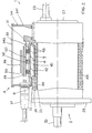
- eine Schnittdarstellung der elektrischen Antriebseinheit,
- Figur 3
- eine Detailansicht des Kühlereinlegeteils.
- Die elektrische Antriebseinheit 1 aus Elektromotor 2 und Elektronikmodul 3 soll bsp. zur Bereitstellung elektrischer Leistung für die Hilfsantriebe eines mittels einer Brennstoffzelle angetriebenen Kraftfahrzeugs herangezogen werden.
Der Elektromotor 2 der elektrischen Antriebseinheit 1 ist bsp. ein wassergekühlter Reluktanz.Motor ("SR-Motor" "shift reluctance") mit einer Nennleistung von bsp. 8 kW; zwischen der Innenwand 23 und der Außenwand 22 des den Stator des Elektromotors 2 umschließenden Elektromotormotorgehäuses 21 ist der umlaufende außenliegende Kühlkreislauf (Wassermantel 24) zur Aufnahme des Kühlmittels (Kühlwasser 44) angeordnet. Der Elektromotor 2 beitzt zwei axial an gegenüberliegenden Stirnseiten 27, 28 angebrachte Lagerschilde 25, 26: der erste, an der Stirnseite 28 befindliche Lagerschild 26 des Elektromotors 2 ist mit der Arbeitswelle (Antriebswelle) verbunden, der zweite, an der Stirnseite 27 befindliche Lagerschild 25 des Elektromotors 2 ist als Einlauf und Ablauf des Kühlwassers 44 mit dem Wassermantel 24 verbunden.
Das Elektronikmodul 3 der elektrischen Antriebseinheit 1 besteht aus - einer in einer ersten Schaltungsebene angeordneten Leistungseinheit 31, deren Bauelemente auf einem für hohe Ströme und für eine ausreichende Abführung der Verlustleistung geeigneten Trägerkörper 311 aufgebracht sind; bsp. sind die Halbleiterbauelemente der Leistungseinheit 31 auf DCB-Substrate 311 ("Direct Copper Bonding": Keramikträger zwischen zwei Kupferschichten) aufgebracht, wobei die erforderliche Stromtragfähigkeit der Leistungseinheit 31 bsp. durch Parallelschaltung dreier DCB-Substrate 311 erreicht wird. Ein DCB-Substrat 311 besitzt bsp. die Abmessungen 35 mm x 49 mm, wobei die beiden Kupferschichten bsp. eine Dikke von jeweils 300 µm und der dazwischen angeordnete, bsp. aus AIN bestehende Keramikträger bsp. eine Dicke von 0.635 mm besitzt. Die DCB-Substrate 311 sind unmittelbar auf das aus einem gut wärmeleitfähigen Material bestehende und für die Leistungseinheit 31 als Kühlkörper fungierende Kühlereinlegeteil 4 aufgebracht und mit diesem bsp. durch Löten verbunden.
- einer Verbindungseinheit 32, die in einer zweiten Schaltungsebene oberhalb der Leistungseinheit 31 auf einer Hochstrom-Leiterplatte 321 angeordnet ist; die Verbindungseinheit 32 dient zur Gleichspannungsverteilung (DC-Verschienung), zur Phasenverschienung der Motorphasen des Elektromotors 2, zur Realisierung von Steuerleitungen für die Ansteuereinheit 33, und zur Kontaktierung von Bauelementen der Leistungseinheit 31 und Ansteuereinheit 33 sowie von weiteren Bauelementen des Elektronikmoduls 3. Bsp. besteht die Hochstrom-Leiterplatte 321 aus einem FR4-Material und besitzt eine Grundfläche von 100 mm x 100 mm; bei einem vierlagigen Aufbau (vier Einzellagen) weist die Hochstrom-Leiterplatte 321 bsp. eine Gesamtdicke von 2.5 mm auf. Beispielsweise besitzen bei einer in vier Leitbahnebenen realisierten Leitbahnstruktur (vierlagiger Aufbau der Hochstrom-Leiterplatte 321) und bei einer Gesamtdicke der Leitbahnstruktur (der bsp. aus Kupfer bestehenden Leiterbahnen) von ca. 500 µm die Leiterbahnen der beiden sich im Innern der Hochstrom-Leiterplatte 321 befindlichen Leitbahnebenen (die beiden Innenlagen) jeweils eine Schichtdicke von 110 µm und die Leiterbahnen der beiden sich auf der Außenseite der Hochstrom-Leiterplatte 321 befindlichen Leitbahnebenen (die beiden Außenlagen) jeweils eine Schichtdicke von 140 µm.
- einer Ansteuereinheit 33, die in einer dritten Schaltungsebene oberhalb der Hochstrom-Leiterplatte 321 der Verbindungseinheit 32 in minimalem senkrechten Abstand auf einem Trägerkörper 331 angeordnet ist; die Bauelemente der Ansteuereinheit 33 werden beispielsweise beidseitig auf eine Leiterplatte als Trägerkörper 331 aufgebracht. Bsp. ist diese Leiterplatte 331 aus einem FR4-Material ausgebildet und besitzt eine Grundfläche von 100 mm x 100 mm; bei einer in sechs Leitbahnebenen realisierten Leitbahnstruktur (sechslagiger Aufbau des Trägerkörpers 331) weist die Leiterplatte 331 bsp. eine Gesamtdicke von 2 mm auf.
- einem Elektronikmodulgehäuse 34 mit integrierten Kfz-tauglichen Stekkeranschlüssen 36, 37 zum Anschluß von Verbindungsleitungen; bsp. sind zwei Steckeranschlüsse 36, 37 vorgesehen, ein Steckeranschluß 37 als Gleichspannungseingang von der Brennstoffzelle und ein Steckeranschluß 36 zum Anschluß von Signalleitungen bzw. Steuerleitungen zum Kraftfahrzeug hin (bsp. zum Anschluß an einen Datenbus des Kraftfahrzeugs, bsp. an einen CAN-Bus). Das Elektronikmodulgehäuse 34 ist bsp. zweigeteilt und besteht bsp. aus einem Gehäuseseitenteil 341 und aus einem auf das Gehäuseseitenteil 341 aufgesetzten und mit diesem verklebten Gehäusedeckel 342.
- weiteren Bauelementen, insbesondere Entstörelementen wie bsp. Kondensatoren und Ferritringen, zur Vermeidung von externen Störeinflüssen wie EMV-Einstrahlungen, Stromwelligkeiten (Ripples) oder Überspannungen etc.; diese weiteren Bauelemente sind mit der Hochstrom-Leiterplatte 321 der Verbindungseinheit 32 bzw. mit dem Elektronikmodulgehäuse 34 elektrisch und/oder mechanisch verbunden.
- Das Kühlereinlegeteil 4 besteht bsp. aus mit Füllstoffen versehenem Al-Druckguß und besitzt bsp. die Abmessungen 121 mm x 76 mm sowie eine Dicke von 10 mm. Wie in der Figur 3 dargestellt, sind an der Unterseite 41 des Kühlereinlegeteils 4 als Geometrieelemente 42 zur Vergrößerung der kühlenden Oberfläche bzw. zur Vorgabe von Strömungskanälen 43 für das Kühlwasser 44 bsp. Rauten angebracht; das Kühlwasser 44 muß demzufolge in den Strömungskanälen 43 zwischen den Rauten 42 hindurchströmen, so daß aufgrund von erzwungener Konvektion eine gute Kühlwirkung durch das Kühlereinlegeteil 4 gewährleistet wird.
Vor dem Zusammenfügen von Elektromotor 2 und Elektronikmodul 3 wird das Kühlereinlegeteil 4 mit der unmittelbar hierauf aufgebrachten Leistungseinheit 31 in eine an die Größe des Kühlereinlegeteils 4 angepaßte Aussparung im Elektronikmodulgehäuse 34 eingelegt. Beim Zusammenfügen von Elektromotor 2 und Elektronikmodul 3 wird das Kühlereinlegeteil 4 in eine Aussparung in der Außenwand 22 des Elektromotorgehäuses 21 formschlüssig eingebracht und mit den Geometrieelementen 42 (Rauten) bündig auf die Innenwand 23 des Elektromotorgehäuses 21 aufgesetzt; hiermit wird das Kühlereinlegeteil 4 in den Wassermantel 24 des Elektromotors 1 integriert und die Kühlung des Elektronikmoduls 3 direkt an die Kühlung des Elektromotors 2 gekoppelt. Die Abdichtung des Kühlereinlegeteils 4 zum Elektromotor 2 hin (d.h. die Abgrenzung des Wassermantels 24 als Kühlkreislauf) kann bsp. mittels einer Formdichtung 6 erfolgen, bsp. mittels eines bsp. aus einem synthetischen Gummi (bsp. aus NBR) bestehenden Formelements 6; hierzu wird die Formdichtung 6 in eine an der Umrandung des Kühlereinlegeteils 4 umlaufende Nut 45 (siehe Figur 3) eingebracht. Die thermische Entkopplung von Kühlereinlegeteil 4 und Innenwand 23 des Elektromotorgehäuses 21 wird mittels einer auf die Unterseite 41 des Kühlereinlegeteils 4 (auf die Geometrieelemente 42 des Kühlereinlegeteils 4) aufgebrachten thermischen Isolationsschicht 7 realisiert, bsp. durch eine (bsp. aufgeklebte) thermische Isolationsfolie 7; die thermische Isolationsfolie 7 ist bsp. als Kunststoffolie mit relativ schlechter Wärmeleitung ausgebildet, bsp. als einseitig klebende Kunststoffolie aus Polyester oder Kapton. - Die elektrische Verbindung zwischen Elektromotor 2 und Elektronikmodul 3 beim Zusammenfügen von Elektromotor 2 und Elektronikmodul 3 erfolgt durch interne Verbindungsleitungen, die durch Aussparungen im Elektromotorgehäuse 21 und Elektronikmodulgehäuse 34 hindurchgeführt werden; die Aussparungen befinden sich bsp. im Bereich des ersten Lagerschilds 26, als Verbindungsleitungen sind bsp. Phasenenden vorgesehen.
Die mechanische Fixierung von Elektromotor 2 und Elektronikmodul 3 beim Zusammenfügen von Elektromotor 2 und Elektronikmodul 3 erfolgt durch Verschraubung des Elektronikmodulgehäuses 34 mit dem Elektromotorgehäuse 21 mittels Befestigungselementen 51 und Schrauben 52, wodurch eine kompakte integrierte elektrische Antriebseinheit 1 gebildet wird.
Claims (9)
- Elektrische Antriebseinheit (1) aus Elektromotor (2) und Elektronikmodul (3), wobei• der Elektromotor (2) ein doppelwandiges Elektromotorgehäuse (21) mit einer Außenwand (22) und einer Innenwand (23) aufweist, zwischen denen ein von einem Kühlmittel (44) durchströmter Kühlkreislauf (24) angeordnet ist,• das Elektronikmodul (3) mindestens eine zu kühlende Funktionseinheit (31) und ein Elektronikmodulgehäuse (34) aufweist,dadurch gekennzeichnet,• daß die zu kühlende Funktionseinheit (31) des Elektronikmoduls (3) auf einem Kühlereinlegeteil (4) angeordnet ist,• daß im Elektronikmodulgehäuse (34) eine zur Aufnahme des Kühlereinlegeteils (4) dienende Aussparung vorgesehen ist,• daß in der Außenwand (22) des Elektromotorgehäuses (21) eine der Aussparung im Elektronikmodulgehäuse (34) entsprechende Aussparung vorgesehen ist, in die das Kühlereinlegeteil (4) derart eingebracht ist, daß es an der Innenwand (23) des Elektromotorgehäuses (21) anliegt.
- Elektrische Antriebseinheit nach Anspruch 1, dadurch gekennzeichnet, daß die Unterseite (41) des Kühlereinlegeteils (4) zur Vergrößerung der vom Kühlmittel (44) umströmten Oberfläche mit Geometrieelementen (42) versehen ist.
- Elektrische Antriebseinheit nach Anspruch 1 oder 2, dadurch gekennzeichnet, daß auf der Unterseite (41) des Kühlereinlegeteils (4) eine thermische Isolationsschicht (7) aufgebracht ist.
- Elektrische Antriebseinheit nach Anspruch 3, dadurch gekennzeichnet, daß die thermische Isolationsschicht (7) als einseitig selbstklebende Kunststoffolie ausgebildet ist.
- Elektrische Antriebseinheit nach einem der Ansprüche 1 bis 4, dadurch gekennzeichnet, daß das Elektronikmodulgehäuse (34) Aussparungen für Steckeranschlüsse (36, 37) zum Anschluß von Verbindungsleitungen für die Spannungsversorgung und von Steuerleitungen aufweist.
- Elektrische Antriebseinheit nach einem der Ansprüche 1 bis 5, dadurch gekennzeichnet, daß die elektrische Verbindung von Elektromotor (2) und Elektronikmodul (3) über interne Verbindungsleitungen erfolgt.
- Elektrische Antriebseinheit nach einem der Ansprüche 1 bis 6, dadurch gekennzeichnet, daß das Elektronikmodul (3) mehrere Funktionseinheiten (31; 32; 33) aufweist, die auf jeweils einem Trägerkörper (311; 321; 331) in verschiedenen Schaltungsebenen beabstandet voneinander angeordnet sind.
- Elektrische Antriebseinheit nach Anspruch 7, dadurch gekennzeichnet, daß das Elektronikmodul (3) als beabstandet voneinander angeordnete Funktionseinheiten (31; 32; 33) aufweist:• eine Leistungseinheit (31) mit einem Substrat als Trägerkörper (311), der auf dem Kühlereinlegeteil (4) angeordnet ist,• eine auf einer Hochstrom-Leiterplatte als Trägerkörper (321) angeordneten Verbindungseinheit (32) zur Spannungsversorgung, Phasenverschienung und zur Kontaktierung von Bauelementen,• eine Ansteuereinheit (33) mit einer Leiterplatte als Trägerkörper (331).
- Elektrische Antriebseinheit nach Anspruch 8, dadurch gekennzeichnet, daß auf der Oberseite und/oder der Unterseite der Hochstrom-Leiterplatte (331) Verbindungselemente mit Ausgleichssicken vorgesehen sind.
Applications Claiming Priority (2)
| Application Number | Priority Date | Filing Date | Title |
|---|---|---|---|
| DE19817333A DE19817333C5 (de) | 1998-04-18 | 1998-04-18 | Elektrische Antriebseinheit aus Elektromotor und Elektronikmodul |
| DE19817333 | 1998-04-18 |
Publications (3)
| Publication Number | Publication Date |
|---|---|
| EP0951131A2 EP0951131A2 (de) | 1999-10-20 |
| EP0951131A3 EP0951131A3 (de) | 2002-10-02 |
| EP0951131B1 true EP0951131B1 (de) | 2006-09-13 |
Family
ID=7865025
Family Applications (1)
| Application Number | Title | Priority Date | Filing Date |
|---|---|---|---|
| EP99106967A Expired - Lifetime EP0951131B1 (de) | 1998-04-18 | 1999-04-09 | Elektrische Antriebseinheit aus Elektromotor und Elektronikmodul |
Country Status (4)
| Country | Link |
|---|---|
| US (1) | US6198183B1 (de) |
| EP (1) | EP0951131B1 (de) |
| JP (1) | JP4320688B2 (de) |
| DE (2) | DE19817333C5 (de) |
Cited By (1)
| Publication number | Priority date | Publication date | Assignee | Title |
|---|---|---|---|---|
| DE102021208579A1 (de) | 2021-08-06 | 2023-02-09 | Zf Friedrichshafen Ag | Getriebe für ein Kraftfahrzeug |
Families Citing this family (164)
| Publication number | Priority date | Publication date | Assignee | Title |
|---|---|---|---|---|
| US6348752B1 (en) | 1992-04-06 | 2002-02-19 | General Electric Company | Integral motor and control |
| JP3886696B2 (ja) * | 1999-04-27 | 2007-02-28 | アイシン・エィ・ダブリュ株式会社 | 駆動装置 |
| DE19956429A1 (de) * | 1999-11-24 | 2001-06-13 | Grundfos As | Elektromotor für insbesondere eine Kreiselpumpe |
| DE10011956A1 (de) * | 2000-03-11 | 2001-09-27 | Mannesmann Sachs Ag | Elektrische Maschine sowie Antriebsanordnung für ein Fahrzeug |
| DE10102621B4 (de) * | 2001-01-20 | 2006-05-24 | Conti Temic Microelectronic Gmbh | Leistungsmodul |
| JP3951880B2 (ja) * | 2001-10-30 | 2007-08-01 | 株式会社デンソー | モータ装置 |
| US6720689B2 (en) | 2001-12-11 | 2004-04-13 | Black & Decker Inc. | Brushless motor having capacitors mounted on sidewall of motor housing |
| US6661140B2 (en) | 2001-12-11 | 2003-12-09 | Black & Decker Inc. | Brushless motor having housing enabling alignment of stator and sensor |
| US6570284B1 (en) | 2001-12-11 | 2003-05-27 | Black & Decker Inc. | Brushless motor having double insulation |
| JP3730953B2 (ja) * | 2001-12-14 | 2006-01-05 | フアウレシア・アウトジッツェ・ゲゼルシヤフト・ミト・ベシユレンクテル・ハフツング・ウント・コンパニー・コマンデイトゲゼルシヤフト | 自動車用の調節モータ |
| JP3882994B2 (ja) * | 2001-12-27 | 2007-02-21 | アイシン・エィ・ダブリュ株式会社 | 電動機制御ユニット冷却装置 |
| JP3593102B2 (ja) * | 2002-01-08 | 2004-11-24 | 三菱電機株式会社 | 電動パワーステアリング装置 |
| DE10302791B4 (de) * | 2002-01-30 | 2016-03-17 | Denso Corporation | Elektrokompressor |
| DE10204200A1 (de) * | 2002-02-01 | 2003-08-21 | Conti Temic Microelectronic | Leistungsmodul |
| EP1363026A3 (de) * | 2002-04-26 | 2004-09-01 | Denso Corporation | Wechselrichter-integrierter Motor für einen Kraftwagen |
| JP3760887B2 (ja) * | 2002-04-26 | 2006-03-29 | 株式会社デンソー | 車両用インバータ一体型モータ |
| JP3818213B2 (ja) * | 2002-05-01 | 2006-09-06 | 株式会社デンソー | 電動圧縮機 |
| US6914357B2 (en) * | 2002-06-10 | 2005-07-05 | Visteon Global Technologies, Inc. | Electric machine with integrated power electronics |
| JP3997855B2 (ja) * | 2002-07-15 | 2007-10-24 | 株式会社豊田自動織機 | 電動コンプレッサ |
| DE10239512A1 (de) | 2002-08-28 | 2004-03-11 | Minebea Co. Ltd., A Japanese Corporation | Anordnung zur Unterbringung der Leistungs- und Steuerelektronik eines Elektromotors |
| KR100614011B1 (ko) * | 2002-09-13 | 2006-08-21 | 아이신에이더블류 가부시키가이샤 | 구동장치 |
| DE60331611D1 (de) * | 2002-09-13 | 2010-04-15 | Aisin Aw Co | Antriebseinheit |
| KR100689940B1 (ko) * | 2002-09-13 | 2007-03-09 | 아이신에이더블류 가부시키가이샤 | 구동 장치 |
| EP1398402A3 (de) * | 2002-09-16 | 2004-09-01 | Maschinenfabrik Rieter Ag | Luftspinnmaschine mit Reluktanzmotoren |
| EP1422810A1 (de) | 2002-11-21 | 2004-05-26 | Continental ISAD Electronic Systems GmbH & Co. oHG | Kraftfahrzeug-Antriebssystem |
| JP4186109B2 (ja) * | 2003-06-25 | 2008-11-26 | アイシン・エィ・ダブリュ株式会社 | 駆動装置 |
| DE502004008097D1 (de) | 2003-07-08 | 2008-10-30 | Continental Automotive Gmbh | Schaltungsanordnung zur emv-entstörtung eines gleichstrommotors sowie schaltmodul |
| US20050023912A1 (en) * | 2003-07-28 | 2005-02-03 | A.O. Smith Corporation | Electric motor for hydromassage bathtubs |
| DE10356224A1 (de) * | 2003-12-02 | 2005-06-30 | Pwb-Ruhlatec Industrieprodukte Gmbh | Taktscheibenbefestigung |
| EP1544982B1 (de) * | 2003-12-20 | 2010-03-10 | Grundfos a/s | Klemmenkasten |
| DK1735893T3 (da) * | 2004-04-01 | 2008-11-24 | Sew Eurodrive Gmbh & Co | Elektromotor og serie af elektromotorer |
| US7180212B2 (en) * | 2004-07-02 | 2007-02-20 | Visteon Global Technologies, Inc. | Electric machine with integrated electronics in a circular/closed-loop arrangement |
| US7635932B2 (en) * | 2004-08-18 | 2009-12-22 | Bluwav Systems, Llc | Dynamoelectric machine having heat pipes embedded in stator core |
| DE202004015038U1 (de) * | 2004-09-24 | 2005-11-10 | Dbt Gmbh | Antriebseinrichtung für Bergbaugewinnungsmaschinen |
| US7687945B2 (en) * | 2004-09-25 | 2010-03-30 | Bluwav Systems LLC. | Method and system for cooling a motor or motor enclosure |
| US7199496B2 (en) * | 2005-01-18 | 2007-04-03 | Oriental Motor Boston Technology Group Incorporated | Integrated electric motor and drive, optimized for high-temperature operation |
| JP4718936B2 (ja) * | 2005-04-18 | 2011-07-06 | 三菱重工業株式会社 | インバータ内蔵圧縮機 |
| US7629715B1 (en) * | 2005-05-31 | 2009-12-08 | Synchrony, Inc. | Systems, devices and methods for driving machinery |
| DE102005026779A1 (de) | 2005-06-10 | 2006-12-28 | Bayerische Motoren Werke Ag | Elektrische Antriebseinrichtung |
| US7273357B2 (en) * | 2005-08-10 | 2007-09-25 | Mitsubishi Heavy Industries, Ltd. | Control device for electric compressor |
| DE102005041136B4 (de) | 2005-08-30 | 2023-11-02 | Sew-Eurodrive Gmbh & Co Kg | Umrichtermotor und Verfahren |
| JP4539531B2 (ja) * | 2005-10-26 | 2010-09-08 | トヨタ自動車株式会社 | 車両の駆動装置 |
| US7701095B2 (en) * | 2006-07-28 | 2010-04-20 | Danotek Motion Technologies | Permanent-magnet generator and method of cooling |
| DE102006035697A1 (de) * | 2006-08-01 | 2008-02-07 | Temic Automotive Electric Motors Gmbh | Maschinengehäuse einer elektrischen Maschine |
| DE102006035696A1 (de) * | 2006-08-01 | 2008-02-07 | Temic Automotive Electric Motors Gmbh | Maschinengehäuse einer elektrischen Maschine |
| DE102006036493A1 (de) * | 2006-08-04 | 2008-02-21 | Oerlikon Leybold Vacuum Gmbh | Vakuumpumpe |
| JP4675311B2 (ja) * | 2006-11-16 | 2011-04-20 | トヨタ自動車株式会社 | モータのハウジングの内部にモータと一体的に収容されるインバータおよびコンデンサの冷却構造、その冷却構造を備えたモータユニットならびにハウジング |
| US8007255B2 (en) * | 2006-11-22 | 2011-08-30 | Mitsubishi Heavy Industries, Ltd. | Inverter-integrated electric compressor with inverter storage box arrangement |
| DE102007052445B4 (de) | 2006-12-20 | 2024-02-01 | Sew-Eurodrive Gmbh & Co Kg | System |
| DE102007029377A1 (de) * | 2007-06-26 | 2009-01-08 | Continental Automotive Gmbh | Verfahren zur Wärmeabfuhr von elektronischen Bauteilen zum Betrieb einer Flüssigkeitspumpe |
| DE102007034915B4 (de) * | 2007-07-24 | 2011-01-05 | Sew-Eurodrive Gmbh & Co. Kg | Motoranschlusskasten und Umrichtermotor |
| JP5285258B2 (ja) * | 2007-09-28 | 2013-09-11 | 三菱重工業株式会社 | 電動圧縮機 |
| CA2721627C (en) * | 2008-04-17 | 2016-02-09 | Synchrony, Inc. | High-speed permanent magnet motor and generator with low-loss metal rotor |
| JP2011520410A (ja) | 2008-04-18 | 2011-07-14 | シンクロニー,インコーポレイテッド | 集積電子工学を用いた磁力スラスト軸受 |
| EP2110929B1 (de) * | 2008-04-18 | 2018-08-29 | Grundfos Management a/s | Frequenzumrichter auf einem Motor |
| US9583991B2 (en) | 2009-06-24 | 2017-02-28 | Synchrony, Inc. | Systems, devices, and/or methods for managing magnetic bearings |
| EP2308708B1 (de) * | 2009-09-16 | 2016-08-17 | swissauto powersport llc | Elektrofahrzeug mit Reichweitenverlängerung |
| US9187083B2 (en) | 2009-09-16 | 2015-11-17 | Polaris Industries Inc. | System and method for charging an on-board battery of an electric vehicle |
| US8324769B2 (en) * | 2009-09-23 | 2012-12-04 | Rbc Manufacturing Corporation | Motor controller for an electric motor |
| KR20110053084A (ko) * | 2009-11-13 | 2011-05-19 | 엘지전자 주식회사 | 동력 모듈 및 이를 포함하는 자동차 |
| US9276448B2 (en) | 2009-12-10 | 2016-03-01 | Siemens Aktiengesellschaft | Condition monitoring system for a motor |
| US20120286598A1 (en) * | 2009-12-18 | 2012-11-15 | Sensoplan Gmbh | Rotor of an Electric Generator for Generating Electricity in Power Plants |
| JP5517650B2 (ja) * | 2010-02-01 | 2014-06-11 | 三菱重工業株式会社 | インバータ一体型電動圧縮機 |
| WO2011104763A1 (ja) * | 2010-02-26 | 2011-09-01 | 三菱電機株式会社 | 回転機 |
| EP2586121B1 (de) | 2010-06-23 | 2019-12-11 | Synchrony, Inc. | Geteiltes magnetisches axialdrucklager |
| CH703820A1 (de) * | 2010-09-21 | 2012-03-30 | Alstom Hydro France | Luftgekühlter generator. |
| US8546984B2 (en) * | 2010-11-03 | 2013-10-01 | Nidec Motor Corporation | Pump motor control assembly |
| US9780716B2 (en) | 2010-11-19 | 2017-10-03 | General Electric Company | High power-density, high back emf permanent magnet machine and method of making same |
| US9685900B2 (en) | 2010-11-19 | 2017-06-20 | General Electric Company | Low-inductance, high-efficiency induction machine and method of making same |
| US20120126728A1 (en) * | 2010-11-19 | 2012-05-24 | El-Refaie Ayman Mohamed Fawzi | Integrated electric machine and silicon carbide power converter assembly and method of making same |
| JP2012153243A (ja) * | 2011-01-26 | 2012-08-16 | Hitachi Automotive Systems Ltd | 電動パワーステアリングの制御装置 |
| JP5626085B2 (ja) * | 2011-04-12 | 2014-11-19 | コベルコ建機株式会社 | ハイブリッド建設機械 |
| CN102158014B (zh) * | 2011-05-13 | 2012-10-31 | 东方电气集团东风电机有限公司 | 电驱动系统一体化水冷结构 |
| DE102012000986B3 (de) * | 2012-01-22 | 2013-05-23 | Arburg Gmbh + Co Kg | Hydraulikeinrichtung mit einer Temperiereinrichtung |
| EP2639943B1 (de) * | 2012-03-15 | 2015-02-25 | Grundfos Holding A/S | Elektromotor |
| JP5915384B2 (ja) * | 2012-05-30 | 2016-05-11 | 株式会社豊田自動織機 | 電動圧縮機 |
| CN102751851A (zh) * | 2012-06-05 | 2012-10-24 | 深圳市英威腾电气股份有限公司 | 用于爆炸性气体环境的变频器 |
| JP5874838B2 (ja) * | 2012-09-19 | 2016-03-02 | 日産自動車株式会社 | 電動車両用強電ユニットの搭載構造 |
| US9356492B2 (en) | 2013-05-30 | 2016-05-31 | Remy Technologies, Llc | Electric machine with liquid cooled housing |
| DE102013217890A1 (de) * | 2013-09-06 | 2015-03-12 | Zf Friedrichshafen Ag | Elektromaschinengehäuse und Fahrzeugantrieb-Elektromaschine |
| DE102013110466A1 (de) * | 2013-09-23 | 2015-03-26 | Dr. Ing. H.C. F. Porsche Aktiengesellschaft | Elektromaschine für den Einsatz im KFZ-Bereich |
| DE102013021745A1 (de) * | 2013-12-20 | 2015-06-25 | Sew-Eurodrive Gmbh & Co Kg | Umrichtermotor |
| DE102013021740A1 (de) * | 2013-12-20 | 2015-06-25 | Sew-Eurodrive Gmbh & Co Kg | Umrichtermotor |
| ES2481215B1 (es) * | 2014-01-08 | 2015-05-06 | Smartlift, S.L. | Dispositivo de accionamiento integral para ascensor |
| SG11201607440YA (en) * | 2014-03-07 | 2016-10-28 | Mark Tuffley | Composition and method for enhancing wound healing |
| DE102014207115A1 (de) * | 2014-04-14 | 2015-10-15 | Zf Friedrichshafen Ag | Leistungsverarbeitende Schaltungsanordnung |
| DE102014209176A1 (de) * | 2014-05-15 | 2015-11-19 | Schaeffler Technologies AG & Co. KG | Grundgehäuse für einen Radnabenmotor sowie Radnabenmotor mit dem Grundgehäuse |
| AU2015292922B2 (en) * | 2014-07-21 | 2019-05-23 | Prime Datum Development Company, Llc | Power dense motor with thermal management capability |
| JP6442922B2 (ja) * | 2014-08-22 | 2018-12-26 | 日本電産株式会社 | モータ |
| CN107078595B (zh) * | 2014-09-30 | 2019-11-05 | 日产自动车株式会社 | 旋转电机系统 |
| DE102014114837A1 (de) * | 2014-10-13 | 2016-04-14 | Bitzer Kühlmaschinenbau Gmbh | Kältemittelverdichter |
| DE102014221358B4 (de) * | 2014-10-21 | 2026-03-19 | Volkswagen Aktiengesellschaft | Verfahren zur Herstellung eines als Druckgussbauteil ausgebildeten Gehäuseteils eines Gehäuses zur Anordnung eines elektrischen Fahrmotors in einem Kraftfahrzeug und Gehäuse zur Anordnung eines elektrischen Fahrmotors in einem Kraftfahrzeug |
| DE102014016171A1 (de) * | 2014-11-03 | 2016-02-11 | Audi Ag | Elektrische Antriebseinrichtung |
| US10300786B2 (en) | 2014-12-19 | 2019-05-28 | Polaris Industries Inc. | Utility vehicle |
| DE102014019433A1 (de) * | 2014-12-22 | 2016-06-23 | Audi Ag | Elektronikbaueinheit für einen Elektromotor eines Einzelradantriebs eines Kraftfahrzeugs, Einzelradantrieb sowie Kraftfahrzeug |
| AU2016265556B2 (en) | 2015-05-15 | 2019-05-02 | Polaris Industries Inc. | Utility vehicle |
| BR112017025208B1 (pt) * | 2015-05-26 | 2022-06-28 | Nissan Motor Co., Ltd. | Aparelho rotativo elétrico integrado mecânica e eletricamente |
| JP6560033B2 (ja) * | 2015-06-25 | 2019-08-14 | 株式会社日立製作所 | 回転電機、並びに回転電機の冷却システム |
| DE102015219095A1 (de) * | 2015-10-02 | 2017-04-06 | Robert Bosch Gmbh | Antriebseinheit und Aggregat mit Kühlung |
| KR102358278B1 (ko) | 2016-03-11 | 2022-02-04 | 아이티티 매뉴팩츄어링 엔터프라이즈, 엘엘씨 | 다층의 전력 및 제어 인쇄 회로 기판 조립체를 구비한 전력 평면을 갖는, 펌프 또는 회전 디바이스를 구동하기 위한 모터 조립체 |
| DE102016204811A1 (de) * | 2016-03-23 | 2017-09-28 | Robert Bosch Gmbh | Steuermodul zur Ansteuerung wenigstens eines elektrisch betätigbaren Aktuators |
| GB2549086B (en) * | 2016-03-30 | 2022-09-07 | Advanced Electric Machines Group Ltd | Electrical sub-assembly |
| FR3052305B1 (fr) * | 2016-06-06 | 2023-04-14 | Leroy Somer Moteurs | Carcasse de machine electrique |
| US10118477B2 (en) | 2016-06-14 | 2018-11-06 | Polaris Industries Inc. | Hybrid utility vehicle |
| DE102016218127A1 (de) | 2016-09-21 | 2018-03-22 | Voith Patent Gmbh | Kühlung für eine Hybridantriebsanordnung |
| GB201616495D0 (en) * | 2016-09-28 | 2016-11-09 | Electronica Products Limited | Liquid cooled heatsink |
| CN106357043B (zh) * | 2016-10-14 | 2018-09-18 | 珠海格力电器股份有限公司 | 电机和压缩机 |
| CN106712368A (zh) * | 2016-12-14 | 2017-05-24 | 合普动力股份有限公司 | 电动汽车用一体化电机控制器水冷机壳 |
| CN106533035A (zh) * | 2016-12-30 | 2017-03-22 | 合普动力股份有限公司 | 电动汽车用一体化电机控制器 |
| US11444513B2 (en) * | 2017-02-07 | 2022-09-13 | Nidec Motor Corporation | Motor controller can with synthetic housing and metal heat sink |
| FR3071978B1 (fr) * | 2017-09-29 | 2020-06-19 | Valeo Equipements Electriques Moteur | Circuit de refroidissement avec liquide pour machine electrique tournante |
| DE102017220970A1 (de) * | 2017-11-23 | 2019-05-23 | Baumüller Nürnberg GmbH | Antrieb |
| US10700571B2 (en) | 2017-12-08 | 2020-06-30 | Toyota Motor Engineering & Manufacturing North America, Inc. | Cooling system for vehicle motor drive |
| DE102018109614A1 (de) * | 2018-04-20 | 2019-10-24 | Dbk David + Baader Gmbh | Systemintegration von elektrischen Komponenten in Elektro- oder Hybridfahrzeugen |
| DE102018207007A1 (de) * | 2018-05-07 | 2019-11-07 | Audi Ag | Flüssigkeitsgekühltes elektrisches Antriebssystem |
| DE102018113099A1 (de) * | 2018-06-01 | 2019-12-05 | Thyssenkrupp Ag | Gehäusebaugruppe für einen elektrischen Antrieb oder eine elektrische Antriebseinheit, Motor und Fahrzeug |
| US10780770B2 (en) | 2018-10-05 | 2020-09-22 | Polaris Industries Inc. | Hybrid utility vehicle |
| CN109474134A (zh) * | 2018-11-05 | 2019-03-15 | 武汉船用电力推进装置研究所(中国船舶重工集团公司第七二研究所) | 一种电动汽车驱动模块的水冷接口连接密封方法 |
| CN109474135A (zh) * | 2018-11-05 | 2019-03-15 | 武汉船用电力推进装置研究所(中国船舶重工集团公司第七二研究所) | 一种电动汽车驱动模块 |
| CN109378945B (zh) * | 2018-12-10 | 2024-07-02 | 上海伊控动力系统有限公司 | 一种深度集成的电驱动系统 |
| DE102018222734A1 (de) * | 2018-12-21 | 2020-06-25 | Conti Temic Microelectronic Gmbh | Elektromotor |
| CN113287251A (zh) * | 2019-01-10 | 2021-08-20 | 三菱重工发动机和增压器株式会社 | 马达和逆变器一体型旋转电机 |
| USD947125S1 (en) * | 2019-03-01 | 2022-03-29 | Cummins Generator Technologies Limited | Electrical generator |
| US11628942B2 (en) | 2019-03-01 | 2023-04-18 | Pratt & Whitney Canada Corp. | Torque ripple control for an aircraft power train |
| WO2020180367A1 (en) | 2019-03-01 | 2020-09-10 | United Technologies Advanced Projects Inc. | Torque balancing for hybrid electric propulsion systems and aircraft utilizing hybrid electric propulsion systems |
| US11732639B2 (en) | 2019-03-01 | 2023-08-22 | Pratt & Whitney Canada Corp. | Mechanical disconnects for parallel power lanes in hybrid electric propulsion systems |
| WO2020180374A1 (en) | 2019-03-01 | 2020-09-10 | United Technologies Advanced Projects Inc. | Distributed propulsion configurations for aircraft having mixed drive systems |
| JP7271239B2 (ja) * | 2019-03-12 | 2023-05-11 | 本田技研工業株式会社 | モータユニット |
| JP7280721B2 (ja) * | 2019-03-12 | 2023-05-24 | 本田技研工業株式会社 | モータユニットおよびモータユニットの製造方法 |
| US11535392B2 (en) | 2019-03-18 | 2022-12-27 | Pratt & Whitney Canada Corp. | Architectures for hybrid-electric propulsion |
| DE102019109313B4 (de) | 2019-04-09 | 2021-09-30 | Schaeffler Technologies AG & Co. KG | Elektrischer Antrieb mit Wärmetauscherabschnitt |
| WO2020223379A1 (en) | 2019-04-30 | 2020-11-05 | Polaris Industries Inc. | Vehicle |
| US11370266B2 (en) | 2019-05-16 | 2022-06-28 | Polaris Industries Inc. | Hybrid utility vehicle |
| US10965183B2 (en) | 2019-06-14 | 2021-03-30 | Honeywell International Inc. | Integrated traction drive system |
| DE102019117893B4 (de) * | 2019-07-03 | 2021-10-07 | Dr. Ing. H.C. F. Porsche Aktiengesellschaft | Antriebsstrang für ein Kraftfahrzeug mit einer direktgekühlten elektrischen Maschine und einem Getriebe, Kraftfahrzeug |
| USD946523S1 (en) * | 2019-09-09 | 2022-03-22 | Cummins Generator Technologies Limited | Electrical generator |
| JPWO2021065299A1 (de) * | 2019-09-30 | 2021-04-08 | ||
| US10888036B1 (en) * | 2019-12-18 | 2021-01-05 | Toyota Motor Engineering & Manufacturing North America, Inc. | Thermal management assemblies for electronic assemblies circumferentially mounted on a motor |
| US11153996B2 (en) * | 2019-12-18 | 2021-10-19 | Toyota Motor Engineering & Manufacturing North America, Inc. | Thermal management assemblies for electronic assemblies mounted on a motor end |
| US12482595B2 (en) * | 2019-12-20 | 2025-11-25 | At&S Austria Technologie & Systemtechnik Ag | Component carrier with embedded magnetic inlay and integrated coil structure |
| DE102020214816A1 (de) * | 2019-12-30 | 2021-07-01 | Robert Bosch Gesellschaft mit beschränkter Haftung | Elektronikvorrichtung und Werkzeugmaschine mit der Elektronikvorrichtung |
| US11451156B2 (en) | 2020-01-21 | 2022-09-20 | Itt Manufacturing Enterprises Llc | Overvoltage clamp for a matrix converter |
| US11394264B2 (en) | 2020-01-21 | 2022-07-19 | Itt Manufacturing Enterprises Llc | Motor assembly for driving a pump or rotary device with a low inductance resistor for a matrix converter |
| US11448225B2 (en) | 2020-01-21 | 2022-09-20 | Itt Manufacturing Enterprises Llc | Motor assembly for driving a pump or rotary device having a cooling duct |
| JP7306282B2 (ja) * | 2020-01-30 | 2023-07-11 | 株式会社豊田自動織機 | 電動圧縮機 |
| US11486472B2 (en) | 2020-04-16 | 2022-11-01 | United Technologies Advanced Projects Inc. | Gear sytems with variable speed drive |
| US11691674B2 (en) | 2020-05-15 | 2023-07-04 | Polaris Industries Inc. | Off-road vehicle |
| US12187127B2 (en) | 2020-05-15 | 2025-01-07 | Polaris Industries Inc. | Off-road vehicle |
| DE102020214775A1 (de) | 2020-11-25 | 2022-05-25 | Continental Teves Ag & Co. Ohg | Elektronische Steuerungsvorrichtung, Verfahren und Bremssystem |
| JP7444039B2 (ja) * | 2020-12-09 | 2024-03-06 | トヨタ自動車株式会社 | 電動車両 |
| US11894756B2 (en) | 2021-01-25 | 2024-02-06 | Honeywell International Inc. | Systems and methods for electric propulsion systems for electric engines |
| JP7509048B2 (ja) * | 2021-02-02 | 2024-07-02 | トヨタ自動車株式会社 | 電動車両 |
| US12485981B2 (en) | 2021-03-24 | 2025-12-02 | Polaris Industries Inc. | Electric recreational vehicle |
| CA3156559A1 (en) | 2021-05-05 | 2022-11-05 | Polaris Industries Inc. | Exhaust assembly for a utility vehicle |
| US11668323B2 (en) * | 2021-06-28 | 2023-06-06 | Garrett Transportation I Inc. | Coolant system for integrated e-machine controller for turbomachine |
| DE102021214776A1 (de) | 2021-12-21 | 2023-06-22 | Robert Bosch Gesellschaft mit beschränkter Haftung | E-Achsen-Modul eines elektrischen Fahrzeugs |
| DE102022200734A1 (de) | 2022-01-24 | 2023-07-27 | Robert Bosch Gesellschaft mit beschränkter Haftung | Kühlkörper zur Kühlung von elektronischen Bauelementen und Anordnung mit einem Kühlkörper |
| DE102022001137A1 (de) | 2022-04-01 | 2023-10-05 | Mercedes-Benz Group AG | Elektrische Antriebsvorrichtung für ein Kraftfahrzeug, insbesondere für einen Kraftwagen |
| DE102022109719B4 (de) | 2022-04-22 | 2024-08-08 | Schaeffler Technologies AG & Co. KG | Elektrisches Antriebssystem mit einer Wärmetauscheranordnung mit einem eine Blechplatte aufweisenden Kühlkörper mit integriertem Kühlkanal |
| DE102022109797B4 (de) | 2022-04-22 | 2024-09-26 | Dr. Ing. H.C. F. Porsche Aktiengesellschaft | Antriebssystem für ein wenigstens teilweise elektrisch angetriebenes Kraftfahrzeug |
| US12075601B2 (en) * | 2022-06-03 | 2024-08-27 | Vitesco Technologies USA, LLC | Heat dissipation structure for inverter ground screws of a belt starter generator |
| MX2023006716A (es) | 2022-06-13 | 2023-12-14 | Polaris Inc | Tren de potencia para vehiculo utilitario. |
| US12323025B2 (en) * | 2022-10-24 | 2025-06-03 | Schaeffler Technologies AG & Co. KG | Heat exchanger system for an electric motor with fluid circuits arranged between shafts |
| DE102023118194A1 (de) * | 2023-07-10 | 2025-01-16 | Dr. Ing. H.C. F. Porsche Aktiengesellschaft | Elektrische Antriebseinheit |
Family Cites Families (24)
| Publication number | Priority date | Publication date | Assignee | Title |
|---|---|---|---|---|
| US2734459A (en) * | 1956-02-14 | zimsky | ||
| US2683823A (en) * | 1953-01-19 | 1954-07-13 | Gen Electric | Cooling of electrical apparatus |
| US3833826A (en) * | 1973-06-21 | 1974-09-03 | Gen Electric | Gas-cooled dynamoelectric machine |
| US4447947A (en) * | 1980-11-13 | 1984-05-15 | The United States Of America As Represented By The Secretary Of The Air Force | Process for making fluid-cooled electrical conductor |
| DE3218927A1 (de) * | 1982-05-19 | 1983-11-24 | Klöckner-Humboldt-Deutz AG, 5000 Köln | Gasturbinentriebwerk fuer einen flugkoerper |
| US4739204A (en) * | 1986-01-30 | 1988-04-19 | Mitsubishi Denki Kabushiki Kaisha | Liquid cooled a.c. vehicle generator |
| US4980588A (en) * | 1986-02-14 | 1990-12-25 | Mitsubishi Denki Kabushiki Kaisha | Water-cooled vehicle generator |
| JPS62260544A (ja) * | 1986-04-07 | 1987-11-12 | Mitsubishi Electric Corp | 車両用交流発電機 |
| JPS63257435A (ja) * | 1987-04-13 | 1988-10-25 | Mitsubishi Electric Corp | 車両用交流発電機 |
| WO1988009077A1 (fr) * | 1987-05-08 | 1988-11-17 | Firma Karl Lutz | Moteur electrique, notamment moteur d'entrainement pour pompe electrique portative ou pompe immersible |
| US4961017A (en) * | 1987-09-28 | 1990-10-02 | Akai Electric Co., Ltd. | Stator for use in a brushless motor |
| DE8914756U1 (de) * | 1989-12-15 | 1991-04-11 | Robert Bosch Gmbh, 7000 Stuttgart | Flüssigkeitsgekühlter elektrischer Generator |
| US4975825A (en) * | 1990-01-16 | 1990-12-04 | Sundstrand Corporation | Stacked power converter |
| US5058660A (en) * | 1990-03-09 | 1991-10-22 | Kohler Co. | Shared coolant system for marine generator |
| US5331238A (en) * | 1993-03-01 | 1994-07-19 | Sundstrand Corporation | Apparatus for containment and cooling of a core within a housing |
| DE4311518A1 (de) * | 1993-04-07 | 1994-10-13 | Siemens Ag | Antriebseinrichtung für ein Fahrzeug |
| DE4311431C2 (de) * | 1993-04-07 | 1995-07-13 | Index Werke Kg Hahn & Tessky | Motorspindel für eine Werkzeugmaschine |
| ATA105093A (de) * | 1993-05-28 | 2001-07-15 | Steyr Daimler Puch Ag | Flüssigkeitsgekühlte antriebseinheit für ein elektromobil |
| JP3077490B2 (ja) * | 1993-12-28 | 2000-08-14 | 株式会社荏原製作所 | ポンプ組立体 |
| US5491370A (en) * | 1994-01-28 | 1996-02-13 | General Motors Corporation | Integrated AC machine |
| DE4442867C2 (de) | 1994-12-02 | 1999-09-09 | Mannesmann Sachs Ag | Antriebsanordnung für ein Fahrzeug, insbesondere ein Straßenfahrzeug |
| DE19626213C2 (de) * | 1996-06-29 | 1998-09-17 | Bosch Gmbh Robert | Integrierter drehzahlgeregelter Antrieb |
| DE19635196A1 (de) * | 1996-08-30 | 1998-03-12 | Audi Ag | Kühlanordnung für einen Elektromotor |
| US5763969A (en) * | 1996-11-14 | 1998-06-09 | Reliance Electric Industrial Company | Integrated electric motor and drive system with auxiliary cooling motor and asymmetric heat sink |
-
1998
- 1998-04-18 DE DE19817333A patent/DE19817333C5/de not_active Expired - Lifetime
-
1999
- 1999-04-07 JP JP13461099A patent/JP4320688B2/ja not_active Expired - Lifetime
- 1999-04-09 EP EP99106967A patent/EP0951131B1/de not_active Expired - Lifetime
- 1999-04-09 DE DE59913842T patent/DE59913842D1/de not_active Expired - Lifetime
- 1999-04-19 US US09/294,655 patent/US6198183B1/en not_active Expired - Lifetime
Cited By (2)
| Publication number | Priority date | Publication date | Assignee | Title |
|---|---|---|---|---|
| DE102021208579A1 (de) | 2021-08-06 | 2023-02-09 | Zf Friedrichshafen Ag | Getriebe für ein Kraftfahrzeug |
| DE102021208579B4 (de) | 2021-08-06 | 2025-03-20 | Zf Friedrichshafen Ag | Getriebe für ein Kraftfahrzeug |
Also Published As
| Publication number | Publication date |
|---|---|
| DE19817333C5 (de) | 2007-04-26 |
| DE19817333C1 (de) | 1999-12-02 |
| JP4320688B2 (ja) | 2009-08-26 |
| US6198183B1 (en) | 2001-03-06 |
| EP0951131A3 (de) | 2002-10-02 |
| JPH11346454A (ja) | 1999-12-14 |
| EP0951131A2 (de) | 1999-10-20 |
| DE59913842D1 (de) | 2006-10-26 |
Similar Documents
| Publication | Publication Date | Title |
|---|---|---|
| EP0951131B1 (de) | Elektrische Antriebseinheit aus Elektromotor und Elektronikmodul | |
| DE112014000153B4 (de) | Leistungsumsetzungsvorrichtung | |
| EP1532723B1 (de) | Anordnung zur unterbringung der leistungs- und steuerelektronik eines elektromotors | |
| DE69632003T2 (de) | Starre-flexible Leiterplatte mit einer Öffnung für einen isolierten Montierungsbereich | |
| DE19854180B4 (de) | Modulgehäuse für Halbleiterbauteile | |
| EP2508054B1 (de) | Leistungselektronische baugruppe und wechselrichteranordnung | |
| EP2334161B1 (de) | Steuergerät | |
| DE10218071B4 (de) | Kondensatormodul und dieses verwendende Halbleitereinrichtung | |
| DE102019206523A1 (de) | Leistungsmodul mit gehäusten Leistungshalbleitern zur steuerbaren elektrischen Leistungsversorgung eines Verbrauchers | |
| DE102014101034B4 (de) | Wärmeabstrahlungsstruktur einer elektrischen Vorrichtung und Verfahren zum Herstellen derselben | |
| DE10056832A1 (de) | Halbleiterbauteil-Moduleinheit | |
| DE112012004496T5 (de) | Gleichspannungs/Gleichspannungs-Umsetzer und Leistungsumsetzungsvorrichtung | |
| EP2849549B1 (de) | Anordnung elektrischer Bauteile und elektrischer Antriebsmotor mit einer solchen Bauteileanordnung | |
| DE19959171A1 (de) | Wechselumrichter | |
| DE102020205236B4 (de) | Leistungswandler | |
| EP0935818B1 (de) | Elektronisches steuergerät | |
| EP0597144A1 (de) | Hybride leistungselektronische Anordnung | |
| DE102008062514A1 (de) | Halbleitermodul-Montagekonstruktion | |
| DE19859739A1 (de) | Kühlvorrichtung, insbesondere zur Verwendung in einem elektronischen Steuergerät | |
| DE102020216395A1 (de) | Fahrzeugsteuermodul mit Kunststoffumhüllung | |
| DE102012216086B4 (de) | Leistungselektronikmodul | |
| DE102019205772A1 (de) | Leistungsmodul mit gehäusten Leistungshalbleitern zur steuerbaren elektrischen Leistungsversorgung eines Verbrauchers | |
| DE102021210597B4 (de) | Leistungshalbleitermodul und Antriebsstrang für ein Fahrzeug aufweisend ein derartiges Leistungshalbleitermodul | |
| DE102013226513A1 (de) | Leiterplatte, Verfahren zum Herstellen derselben und Leiterplattenvorrichtung | |
| US11006513B1 (en) | Electronic assembly having sectional thermal management |
Legal Events
| Date | Code | Title | Description |
|---|---|---|---|
| PUAI | Public reference made under article 153(3) epc to a published international application that has entered the european phase |
Free format text: ORIGINAL CODE: 0009012 |
|
| AK | Designated contracting states |
Kind code of ref document: A2 Designated state(s): AT BE CH CY DE DK ES FI FR GB GR IE IT LI LU MC NL PT SE |
|
| AX | Request for extension of the european patent |
Free format text: AL;LT;LV;MK;RO;SI |
|
| K1C1 | Correction of patent application (title page) published |
Effective date: 19991020 |
|
| RTI1 | Title (correction) |
Free format text: ELECTRIC DRIVE UNIT CONSISTING OF AN ELECTRIC MOTOR AND OF AN ELECTRONIC UNIT |
|
| RAP1 | Party data changed (applicant data changed or rights of an application transferred) |
Owner name: CONTI TEMIC MICROELECTRONIC GMBH |
|
| RAP1 | Party data changed (applicant data changed or rights of an application transferred) |
Owner name: CONTI TEMIC MICROELECTRONIC GMBH Owner name: DAIMLERCHRYSLER AG |
|
| PUAL | Search report despatched |
Free format text: ORIGINAL CODE: 0009013 |
|
| AK | Designated contracting states |
Kind code of ref document: A3 Designated state(s): AT BE CH CY DE DK ES FI FR GB GR IE IT LI LU MC NL PT SE |
|
| AX | Request for extension of the european patent |
Free format text: AL;LT;LV;MK;RO;SI |
|
| 17P | Request for examination filed |
Effective date: 20020918 |
|
| AKX | Designation fees paid |
Designated state(s): DE ES FR GB IT SE |
|
| GRAP | Despatch of communication of intention to grant a patent |
Free format text: ORIGINAL CODE: EPIDOSNIGR1 |
|
| GRAS | Grant fee paid |
Free format text: ORIGINAL CODE: EPIDOSNIGR3 |
|
| RAP1 | Party data changed (applicant data changed or rights of an application transferred) |
Owner name: CONTI TEMIC MICROELECTRONIC GMBH |
|
| GRAA | (expected) grant |
Free format text: ORIGINAL CODE: 0009210 |
|
| AK | Designated contracting states |
Kind code of ref document: B1 Designated state(s): DE ES FR GB IT SE |
|
| PG25 | Lapsed in a contracting state [announced via postgrant information from national office to epo] |
Ref country code: IT Free format text: LAPSE BECAUSE OF FAILURE TO SUBMIT A TRANSLATION OF THE DESCRIPTION OR TO PAY THE FEE WITHIN THE PRE;WARNING: LAPSES OF ITALIAN PATENTS WITH EFFECTIVE DATE BEFORE 2007 MAY HAVE OCCURRED AT ANY TIME BEFORE 2007. THE CORRECT EFFECTIVE DATE MAY BE DIFFERENT FROM THE ONE RECORDED.SCRIBED TIME-LIMIT Effective date: 20060913 Ref country code: GB Free format text: LAPSE BECAUSE OF FAILURE TO SUBMIT A TRANSLATION OF THE DESCRIPTION OR TO PAY THE FEE WITHIN THE PRESCRIBED TIME-LIMIT Effective date: 20060913 |
|
| REG | Reference to a national code |
Ref country code: GB Ref legal event code: FG4D |
|
| REF | Corresponds to: |
Ref document number: 59913842 Country of ref document: DE Date of ref document: 20061026 Kind code of ref document: P |
|
| REG | Reference to a national code |
Ref country code: SE Ref legal event code: TRGR |
|
| PG25 | Lapsed in a contracting state [announced via postgrant information from national office to epo] |
Ref country code: ES Free format text: LAPSE BECAUSE OF FAILURE TO SUBMIT A TRANSLATION OF THE DESCRIPTION OR TO PAY THE FEE WITHIN THE PRESCRIBED TIME-LIMIT Effective date: 20061224 |
|
| ET | Fr: translation filed | ||
| GBV | Gb: ep patent (uk) treated as always having been void in accordance with gb section 77(7)/1977 [no translation filed] |
Effective date: 20060913 |
|
| PLBE | No opposition filed within time limit |
Free format text: ORIGINAL CODE: 0009261 |
|
| STAA | Information on the status of an ep patent application or granted ep patent |
Free format text: STATUS: NO OPPOSITION FILED WITHIN TIME LIMIT |
|
| 26N | No opposition filed |
Effective date: 20070614 |
|
| PGFP | Annual fee paid to national office [announced via postgrant information from national office to epo] |
Ref country code: SE Payment date: 20130418 Year of fee payment: 15 |
|
| REG | Reference to a national code |
Ref country code: SE Ref legal event code: EUG |
|
| PG25 | Lapsed in a contracting state [announced via postgrant information from national office to epo] |
Ref country code: SE Free format text: LAPSE BECAUSE OF NON-PAYMENT OF DUE FEES Effective date: 20140410 |
|
| REG | Reference to a national code |
Ref country code: FR Ref legal event code: PLFP Year of fee payment: 18 |
|
| REG | Reference to a national code |
Ref country code: FR Ref legal event code: PLFP Year of fee payment: 19 |
|
| PGFP | Annual fee paid to national office [announced via postgrant information from national office to epo] |
Ref country code: DE Payment date: 20170430 Year of fee payment: 19 |
|
| REG | Reference to a national code |
Ref country code: FR Ref legal event code: PLFP Year of fee payment: 20 |
|
| PGFP | Annual fee paid to national office [announced via postgrant information from national office to epo] |
Ref country code: FR Payment date: 20180420 Year of fee payment: 20 Ref country code: IT Payment date: 20180423 Year of fee payment: 20 |
|
| REG | Reference to a national code |
Ref country code: DE Ref legal event code: R119 Ref document number: 59913842 Country of ref document: DE |
|
| PG25 | Lapsed in a contracting state [announced via postgrant information from national office to epo] |
Ref country code: DE Free format text: LAPSE BECAUSE OF NON-PAYMENT OF DUE FEES Effective date: 20181101 |