EP1544982B1 - Klemmenkasten - Google Patents
Klemmenkasten Download PDFInfo
- Publication number
- EP1544982B1 EP1544982B1 EP03029515A EP03029515A EP1544982B1 EP 1544982 B1 EP1544982 B1 EP 1544982B1 EP 03029515 A EP03029515 A EP 03029515A EP 03029515 A EP03029515 A EP 03029515A EP 1544982 B1 EP1544982 B1 EP 1544982B1
- Authority
- EP
- European Patent Office
- Prior art keywords
- housing part
- terminal box
- wall
- housing
- heat spreader
- Prior art date
- Legal status (The legal status is an assumption and is not a legal conclusion. Google has not performed a legal analysis and makes no representation as to the accuracy of the status listed.)
- Expired - Lifetime
Links
- 238000005304 joining Methods 0.000 claims description 46
- 239000004020 conductor Substances 0.000 claims description 16
- 230000001681 protective effect Effects 0.000 claims description 12
- 238000004519 manufacturing process Methods 0.000 description 8
- 238000005266 casting Methods 0.000 description 5
- 238000003780 insertion Methods 0.000 description 5
- 230000037431 insertion Effects 0.000 description 5
- 238000009434 installation Methods 0.000 description 3
- 239000000463 material Substances 0.000 description 3
- 239000004033 plastic Substances 0.000 description 3
- 238000003825 pressing Methods 0.000 description 3
- 239000012080 ambient air Substances 0.000 description 2
- 230000000295 complement effect Effects 0.000 description 2
- 238000010276 construction Methods 0.000 description 2
- 238000002347 injection Methods 0.000 description 2
- 239000007924 injection Substances 0.000 description 2
- 230000002093 peripheral effect Effects 0.000 description 2
- BASFCYQUMIYNBI-UHFFFAOYSA-N platinum Chemical compound [Pt] BASFCYQUMIYNBI-UHFFFAOYSA-N 0.000 description 2
- 239000002918 waste heat Substances 0.000 description 2
- 239000000853 adhesive Substances 0.000 description 1
- 230000001070 adhesive effect Effects 0.000 description 1
- 230000001419 dependent effect Effects 0.000 description 1
- 230000000694 effects Effects 0.000 description 1
- 230000005484 gravity Effects 0.000 description 1
- 230000017525 heat dissipation Effects 0.000 description 1
- 230000000977 initiatory effect Effects 0.000 description 1
- 239000007769 metal material Substances 0.000 description 1
- 239000000203 mixture Substances 0.000 description 1
- 239000002991 molded plastic Substances 0.000 description 1
- 229910052697 platinum Inorganic materials 0.000 description 1
- 229910001220 stainless steel Inorganic materials 0.000 description 1
- 239000010935 stainless steel Substances 0.000 description 1
- 230000008646 thermal stress Effects 0.000 description 1
Images
Classifications
-
- H—ELECTRICITY
- H05—ELECTRIC TECHNIQUES NOT OTHERWISE PROVIDED FOR
- H05K—PRINTED CIRCUITS; CASINGS OR CONSTRUCTIONAL DETAILS OF ELECTRIC APPARATUS; MANUFACTURE OF ASSEMBLAGES OF ELECTRICAL COMPONENTS
- H05K7/00—Constructional details common to different types of electric apparatus
- H05K7/20—Modifications to facilitate cooling, ventilating, or heating
- H05K7/2089—Modifications to facilitate cooling, ventilating, or heating for power electronics, e.g. for inverters for controlling motor
- H05K7/209—Heat transfer by conduction from internal heat source to heat radiating structure
-
- H—ELECTRICITY
- H02—GENERATION; CONVERSION OR DISTRIBUTION OF ELECTRIC POWER
- H02K—DYNAMO-ELECTRIC MACHINES
- H02K11/00—Structural association of dynamo-electric machines with electric components or with devices for shielding, monitoring or protection
- H02K11/30—Structural association with control circuits or drive circuits
- H02K11/33—Drive circuits, e.g. power electronics
-
- H—ELECTRICITY
- H02—GENERATION; CONVERSION OR DISTRIBUTION OF ELECTRIC POWER
- H02K—DYNAMO-ELECTRIC MACHINES
- H02K5/00—Casings; Enclosures; Supports
- H02K5/04—Casings or enclosures characterised by the shape, form or construction thereof
- H02K5/22—Auxiliary parts of casings not covered by groups H02K5/06-H02K5/20, e.g. shaped to form connection boxes or terminal boxes
- H02K5/225—Terminal boxes or connection arrangements
-
- H—ELECTRICITY
- H02—GENERATION; CONVERSION OR DISTRIBUTION OF ELECTRIC POWER
- H02K—DYNAMO-ELECTRIC MACHINES
- H02K5/00—Casings; Enclosures; Supports
- H02K5/04—Casings or enclosures characterised by the shape, form or construction thereof
- H02K5/18—Casings or enclosures characterised by the shape, form or construction thereof with ribs or fins for improving heat transfer
Definitions
- the invention relates to a terminal box for an electric motor, in particular as a drive unit of a pump unit.
- the terminal boxes are usually arranged on the outer circumferential surface of a motor housing, for example a pump unit. They make the connection of electric motors with a power supply. Furthermore, they usually include the power and control electronics as well as the operating elements of the motors or pumps. Components of power electronics, such as a frequency converter for speed control of the motor, generate during operation a large amount of heat, which must be dissipated.
- Such terminal boxes go out, for example DE 100 65 796 A1 such as DE 298 80 014 U1 out.
- EP 0 751 606 A describes an alternator for motor vehicles, in which an axial end-side end shield a current control is arranged.
- two heat sinks are arranged on the bearing plate, which are each overbuilt by a distributor. Together, a heat sink and a manifold are bolted to the bearing plate.
- a disadvantage of this arrangement that the heatsink are poorly accessible and attaching the heatsink to the bearing plate is very expensive.
- the object of the present invention is to improve a terminal box for an electric motor to the effect that the waste heat of heat-generating components is sufficiently dissipated, the manufacture and installation of the terminal box easier, d. H. time and cost can be done.
- the terminal box according to the invention for an electric motor has two housing parts. On an inner wall of a first housing part, a heat spreader is provided to dissipate the heat losses of at least one electronic component from the terminal box to the ambient air.
- the heat spreader is held by the first and second housing part in such a way that it lies flat against the inner wall of the first housing part.
- the two housing parts are designed so that they the heat spreader, which is only loosely inserted between them, by their composition non-positively and / or positively in the intended position on the inner wall of the first Force housing part and hold him there without further attachment work and fasteners are required.
- the heat distributor has a contact surface, which is formed corresponding to the inner wall of the first housing part, so that the contact surface at least partially rests flat against the inner wall in order to achieve a good heat transfer.
- the heat transfer can be additionally improved by applying a thermal paste between the contact surface of the heat spreader and the inner wall of the first housing part.
- the first Gedie the outer wall of the terminal box facing away from the stator housing of the motor.
- the second housing part is arranged between the stator housing and the first housing part and is directly against the stator housing.
- the installation of the terminal box is preferably carried out by the loose insertion of the heat spreader in the first housing part and the subsequent placement of the second housing part on the first housing part, whereby the heat spreader is clamped between the two housing parts and pressed against the inner wall of the first housing part.
- the wall of the first housing part, against which the heat distributor rests extends obliquely to the joining direction of the first and second housing parts.
- the joining direction is the direction in which the first and second housing parts are moved towards each other to assemble them.
- the oblique to joining direction wall of the first housing part forms an inclined plane over which the heat spreader can slide when inserted into the position provided for him the wall and preferably rests on the inner wall due to gravity.
- the inclined to the joining direction contact surface of the heat spreader causes, when when assembling the housing parts on the heat spreader clamping or holding force is exerted in the joining direction, at the same time a pressing force is generated on the inner wall of the first housing part, which is normal to the joining direction.
- the heat spreader can be securely clamped and a flat contact with the terminal box wall can be guaranteed.
- the attachment locations of the heat spreader on the two housing parts are preferably offset both in the joining direction and normal to the latter because of the slope of the first housing part. Accordingly, the heat spreader is held in the joining direction between the two housing parts and is pressed normal to the joining direction against the inner wall, which the positive connection and thus optimum heat transfer between the inner wall of the first Housing part and the heat spreader guaranteed.
- the inclined contact surface of the heat spreader is generated by a shell-like design of the first housing part.
- a joining edge for assembly with the second housing part is provided at the open end of the first housing part. This is placed on the joining edge of the first housing part as a bottom, wherein the joining direction is perpendicular to the opening surface in the direction of the closed end of the first housing part.
- the wall on which the heat spreader rests may also be curved, wherein the heat spreader or its contact surface has a corresponding shape.
- the first housing part is curved in such a way that it has the shape of a cylinder or circular cylinder segment, which is open at the side facing away from the curvature.
- the opening thus extends in cross-section substantially in the direction of a chord and is closed by the second housing part.
- the edge of this open surface or opening forms a joining edge against which the second housing part rests.
- the joining direction preferably runs normal to the longitudinal axis of the cylinder segment and direction of extension of the opening.
- the heat distributor is preferably arranged on the inner wall of the first housing part in a region which extends from the joining edge. Its attachment points to the second housing part are preferably located near the joining edge of the first housing part and the connection points on the first housing part spaced from the joining edge.
- the first and the second housing part each have at least one receiving element for holding the heat spreader.
- the object of these receiving elements is to hold the heat spreader on the inner wall of the first housing part, that the heat spreader is set as free of play in this position and is held flat against the inner wall of the first housing part, so that no additional fastening means are needed and a good heat transfer is ensured.
- the receiving elements are preferably formed as recesses and / or projections in one piece with the first and second housing part.
- the receiving elements of the two housing parts are spaced from each other so that the heat spreader, when the first and second housing part are assembled, is positively and / or non-positively pressed against the housing wall.
- the distance between the receiving elements of both housing parts in the assembled state should match the distance of the associated connection points on the heat spreader, so that a backlash-free holder is guaranteed.
- the heat spreader is held by a receiving element spaced from the joining edge on the first housing part.
- the connection of the heat spreader to the second housing part is preferably provided near the common side or joining edge of the two housing parts on a receiving element on the second housing part.
- This receiving element advantageously holds the heat spreader in the joining direction and presses it normal to the joining direction against the inner wall of the first housing part.
- the heat spreader has at least one holding element which is in engagement with at least one receiving element of one of the housing parts in such a way that the holding element bears against a surface of the receiving element facing the inner wall of the first housing part.
- This configuration allows in existing from the holding member of the heat spreader and the receiving element Bracket pairing the initiation of a compressive force in the direction of the inner wall of the first housing part.
- the heat spreader is pressed over the retaining element against the inner wall of the housing.
- a holding element designed in this way is provided with a corresponding receiving element for holding the heat distributor on the second housing part.
- the heat distributor has at least one nose-shaped projection as a holding element.
- at least one cup-shaped receiving element is provided on the second housing part, which preferably receives the holding element without play.
- an elastic lining e.g. be arranged in the form of a seal in the receiving element.
- the nose of the holding element engages in the bowl of the receiving element.
- the holding element lies with its side facing away from the inner wall of the first housing part on a surface of the receiving element, which faces the inner wall of the first housing part, so that the heat spreader is pressed by this to the inner wall of the first housing part or adjacent to this ,
- the receiving element extends to the second housing part in the joining direction of the two housing parts. This facilitates the joining of the heat spreader with the two housing parts.
- the wall of the first housing part extends obliquely to the joining direction of the two housing parts and thus the heat spreader is arranged obliquely to this joining direction
- by contact of the receiving element with the lying obliquely to this heat spreader or its correspondingly directed holding element directed obliquely to the joining direction and normal to the inner wall of the first housing part directed pressure force become.
- a first force component acts in the joining direction and fixes the heat spreader in this direction between the two housing parts.
- a second force component acts normal to the joining direction to the inner wall of the first housing part. This force component causes the system between the heat spreader and the inner wall of the first housing part.
- the receiving element is spaced from the first housing part of the joining edge with the second housing part.
- the receiving element is so far away from the side or joining edge, that a sufficiently large contact surface is available for the heat spreader.
- the first housing part has an oblique housing wall for connecting the heat distributor, the receiving element of the first housing part is offset in relation to the position of the receiving element of the second housing part in a direction normal to the joining direction of the two housing parts due to the inclination of the housing wall. This facilitates the pressing of the heat conductor against the inner wall of the first housing part.
- a preferably spring-trained contact of an electrical protective conductor is arranged, against which a contact region of the heat distributor rests.
- the heat spreader is grounded, for example, for shielding electronic components, which are arranged on the heat spreader.
- the direct connection of the heat spreader to the contact of the electrical protective conductor allows easy contacting, in which no additional electrically conductive connecting elements, such as cables that need to be clamped, are required.
- the contact between the protective conductor and the heat spreader is made by the installation position of the heat spreader between the two housing parts, in which the heat spreader is pressed by the housing parts against the contact.
- the resilient design of the contact allows It compensates for any thermal expansion of the heat spreader, manufacturing tolerances etc. and always ensures a secure contact.
- the contact region of the heat spreader is designed as an arm, which extends transversely to the joining direction of the first and second housing part.
- the arm can bridge a distance between the heat spreader and the contact of the electrical protective conductor in the form of a rigid connection.
- the heat conductor is preferably provided as a metallic casting, the arm-shaped contact region may be integrally disposed on the heat spreader and manufactured in a manufacturing step with this.
- the arm is pressed in its longitudinal direction against the contact.
- the heat spreader is supported on the inner wall of the first housing part adjacent to the receiving element and provided on one of the housing parts of the contact of the electrical protective conductor.
- a system of the heat spreader at the contact of the electrical protective conductor is always guaranteed, thus ensuring its grounding.
- the side edge of the heat spreader rests against the receiving element of the first housing part, and an edge or the arm of the contact region of the heat spreader adjoins the contact of the electrical protective conductor.
- the heat spreader is arranged by this support in its intended position.
- the two housing parts are designed as injection molded plastic parts, while the heat spreader, which bears against the inner wall of the first housing part, consists of a metallic material.
- the heat spreader may be shaped so that it due the different thermal expansion of the two materials during operation further adapts to the shape of the inner wall of the first housing part, whereby the system between the heat spreader and the inner wall of the first housing part is further improved.
- a curved heat spreader bends more when heated than the correspondingly shaped wall of the first housing part, so that the pressure force with which the heat spreader is pressed against the wall, amplified.
- the terminal box is preferably used for a wet running motor of a pump set.
- a first heat spreader on which components of the power electronics of a frequency converter are arranged, is provided on the terminal box.
- the heat spreader has a thermally conductive contact with the stator housing of the engine, via which it dissipates its heat into the liquid-cooled engine.
- at least one further heat spreader is provided on the terminal box, which is arranged on an inner wall of the terminal box and having the features described above.
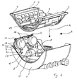
- a terminal box 2 is shown explosively. It is a terminal box 2 a circulating pump. In the terminal box 2, the control electronics of the pump and in particular a frequency converter for operating the pump is arranged.
- the terminal box 2 consists of a first housing part 4 and a second housing part 6, which are both formed as plastic injection molded parts. Its shape is cup-shaped in the form of a circular cylinder segment, wherein it has a spaced from the circular curvature opening surface which extends between two parallel side edges 7 of the first housing part. 4 extends. At the two end surfaces, two large arcuate recesses 8 extending from this opening surface are arranged on the first housing part 4. These recesses correspond to the curved shape of the second housing part 6, which forms the bottom of the terminal box 2 and the first housing part 4 closes at its open side.
- the two housing parts 4 and 6 are at a joining edge, which is formed by the edges of the recesses 8 and the two connecting these parallel side edges 7 of the first housing part 4, wherein the joining direction A, in which the housing parts 4 and 6 are assembled, perpendicular to the opening area of the first housing part 4 extends.
- the two housing parts 4 and 6 are firmly connected.
- the longitudinal axes extending in the joining direction A and are arranged in alignment with four openings 9 for receiving the connecting screws on the second housing part 6.
- the terminal box 2 is arranged with the concave side of the second housing part 6, which faces away from the housing part 4, on the stator housing of the motor (not shown here) of the circulating pump.
- the fastening screws penetrate the second housing part 6.
- the first housing part 4 In its interior, the first housing part 4 has an inner wall 10, which at its end facing the apex line of the first housing part 4, i. the edge of the opening facing away from the end, is bounded by a flat surface 12. This cuts the part-circular cross-section of the first housing part 4 in the form of a chord and extends parallel to the opening surface of the first housing part 4th
- the surface 12 divides the first housing part 4 and forms, in addition to the interior of the terminal box 2, a terminal space 11 arranged in the apex region of the housing part 4 for the terminal contacts of the electrical supply lines.
- This connection space 11 is accessible from outside via a swing-open flap integrated in the peripheral wall of the apex region of the first housing part 4 (not shown here).
- a circuit board 13 is arranged at the interior of the terminal box 2 facing side of the surface 12.
- the second housing part 6 has a recess 19 which corresponds in dimensions to the dimensions of the heat-conducting plate 15.
- the resonateableitplatte 15 protrudes through the recess 19 on the concave side of the second housing part 6 out of the terminal box 2 and is after the connection of the terminal box 2 to the stator of the motor, so that the heat of the réelleableitplatte 15 and the heat of the heat generating components arranged thereon can be dissipated into the liquid-cooled engine.
- a heat spreader 14 At a starting from one of the side edges 7 extending region of the inner wall 10 of the first housing part 4 is a heat spreader 14 at. At this the coils 16 of a DC link of the frequency converter are arranged.
- the portion of the inner wall 10, on which the heat spreader 14 rests, is curved and arranged obliquely to the joining direction A of the two housing parts 4 and 6, so that the heat spreader 14 when inserted into the first housing part 4 on the inner wall 10 can slide in its intended position ,
- the contact surface 18 of the heat spreader 14, which rests against the inner wall 10, is shaped to be complementary to the curved surface of the inner wall 10 and abuts this surface and also obliquely to the joining direction A.
- Fig. 1 shows the heat spreader 14 during insertion, ie it is not yet fully inserted into the first housing part 4.
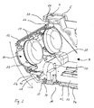
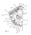
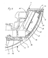
- the Fig. 2 and 3 show a perspective section of the terminal box 2, wherein the heat spreader 14 in Fig. 2 during insertion and in Fig. 3 is shown in its installed state.
- the heat spreader 14 consists of the curved contact surface 18, which bears against the inner wall 10 of the first housing part 4. Normal to this abutment surface 18 is at its concave, i. the inner wall 10 facing away from a substantially circumferential web 20 is arranged, which forms a closed wall of a receiving region of the coil 16 and the coil housing 17.
- the receiving area formed by the web 20 is extended at its two ends in such a way that it surrounds the coils 16 or their coil housing 17 in a circular manner. Together with the contact surface 18 and the coil housings 17, the web 20 forms an electromagnetic shielding of the coils 16.
- two spaced, nose-shaped projecting holding elements 22 are formed, which extend in the installed state substantially in the joining direction A of the two housing parts 4 and 6.
- the holding elements 22 serve for engagement in corresponding receiving elements 24 on the second housing part 6.
- an arm-shaped contact region 26 for grounding the heat distributor 14 is provided on the concave surface of the contact surface 18.
- the arm 26 of the contact area extends from the contact surface 18 of the heat spreader 14 in the interior of the terminal box 2, ie away from the inner wall 10, that its longitudinal axis in the installed state of the heat spreader 14 parallel to the surface 12 of the first housing part. 4 and normal to the joining direction A of the first and second housing part 4 and 6 extends.
- a recess is provided, whereby a contact surface 28, the is perpendicular to the surface 12, is formed.
- the heat spreader 14 is formed as a metallic casting, so that the contact surface 18, the web 20, the support members 22 and the arm-shaped contact portion 26 can be produced by casting as a component, without further processing is required.
- the region of the inner wall 10, against which the heat distributor 14 rests, has, spaced from the side edge 7 near the surface 12, two receiving elements 30 for supporting the heat distributor 14. These are bar-shaped and extend in a direction perpendicular to the surface 12 parallel to the joining direction A. Together with the inner wall 10, the receiving elements 30 form two pointed throats into which the heat spreader 14 engages after insertion with an edge of its contact surface 18 and to supports this, while it rests with its contact surface 18 on the inner wall 10 of the first housing part 4.
- an opening 32 is provided in the vicinity of the inner wall 10.
- the contact 34 of a protective conductor is guided, which is connected to a remote on the interior and the second housing part 6 side of the surface 12 in the terminal compartment 11 arranged grounding plate 36.
- This is a stainless steel sheet, which is used to ground various components of the electronics or pump.
- a terminal for an electrical protective conductor of a connecting line is arranged at the grounding plate 36.
- an opening 37 is provided on the grounding plate 36.
- a grounding screw can be performed to ground components of the board 13.
- the screws for fastening the terminal box 2 to the stator housing abut against the grounding plate 36 so that the grounding plate 36 and the screws also ground the stator housing.
- the contact 34 is formed as a projection of the grounding plate 36, which is angled substantially normal and guided through the opening 32 in the interior of the terminal box 2, so that it protrudes from the surface 12 into the interior of the terminal box 2.
- the contact 34 is resilient due to its dimensions and its material in a direction normal to its longitudinal axis and is so on the one hand in a position to compensate for thermal expansion, manufacturing inaccuracies, etc. of the heat spreader 14 and its contact area 26, and can on the other at investment of Contact surface 28 produce a bias that ensures the ground contact between the arm 26 and the contact 34.
- Fig. 3 illustrates that the arm 26 of the heat spreader 14 is pressed in the installed state with its contact surface 28 against the contact 34 and rests against this. In this way, the heat spreader 14 is grounded and has a further support on the first housing part 4 because of the rigid construction of the arm 26.
- the heat spreader 14 is shown installed between the two housing parts 4 and 6.
- the second housing part 6 On a peripheral edge, which faces the heat distributor 14 adjacent side edge 7 of the first housing part 4, the second housing part 6 has two receiving elements 24, in which engage the holding elements 22 of the heat spreader 14.
- the receiving elements 24 are cup-shaped, opened to the first housing part 4 out and extending in the joining direction A of the two housing parts 4 and 6, which facilitates the joining of the heat spreader 14 with the housing parts 4 and 6.
- the receiving elements 24 each have a side surface 38, which faces the region of the inner wall 10 of the first housing part 4, on which the heat conductor 14 is applied.
- the receiving element 24 may additionally have an elastic lining which is arranged, for example, in the form of a seal in the receiving element 24. Possible manufacturing tolerances or thermal expansion of the heat spreader 14 and its retaining element 22 can be compensated.
- the seal may for example be formed integrally with a arranged between the first and second housing parts 4 and 6 circumferential seal.
- the heat spreader 14 slides along the inner wall 10 of the first housing part 4 to the receiving elements 30.
- the throat between the inner wall 10 and the receiving elements 30 it is supported and lies due to its contact surface 18 corresponding to the inner wall 10 in this position flat against the inner wall 10 at.
- the arm-shaped contact portion 26 with its contact surface 28 against the arranged on the surface 12 contact 34 of the protective conductor so that because of the elastic deflection of the contact 34 and the pressing force exerts the heat spreader 14 via the arm 26 on the contact 34, a reliable Contacting is ensured.
- the heat spreader 14 is clamped by the frictional connection between receiving element 24 and retaining element 22 or a corresponding positive engagement of these elements in the joining direction A between the housing parts 4 and 6, so that the heat spreader 14 is fixed without play on the inner wall 10 of the first housing part 4 and an optimal heat transfer between the heat spreader 14 and the first housing part 4 is ensured by the flush system of the heat spreader 14.
- the assembly of the heat spreader 14 in the terminal box 2 is therefore very simple, since it consists only of the loose insertion of the heat spreader 14 in the first housing part 4 and the subsequent placement of the second housing part 6 on the first housing part 4. An additional attachment of the heat conductor 14 in an additional assembly step is not required.
Landscapes
- Engineering & Computer Science (AREA)
- Microelectronics & Electronic Packaging (AREA)
- Power Engineering (AREA)
- Physics & Mathematics (AREA)
- Thermal Sciences (AREA)
- Cooling Or The Like Of Electrical Apparatus (AREA)
- Coupling Device And Connection With Printed Circuit (AREA)
- Connection Or Junction Boxes (AREA)
- Cable Accessories (AREA)
- Auxiliary Devices For And Details Of Packaging Control (AREA)
- Photovoltaic Devices (AREA)
Description
- Die Erfindung betrifft einen Klemmenkasten für einen Elektromotor insbesondere als Antriebseinheit eines Pumpenaggregats.
- Die Klemmenkästen sind üblicherweise an der äußeren Mantelfläche eines Motorgehäuses, beispielsweise eines Pumpenaggregats, angeordnet. Sie stellen die Verbindung der Elektromotoren mit einer Stromversorgung her. Des Weiteren beinhalten sie meist die Leistungs- und Steuerungselektronik sowie die Bedienelemente der Motoren bzw. Pumpen. Bauteile der Leistungselektronik, wie z.B. ein Frequenzumwandler zur Drehzahlsteuerung des Motors, erzeugen während des Betriebs eine große Eigenwärme, welche abgeführt werden muss. Derartige Klemmenkästen gehen beispielsweise aus
DE 100 65 796 A1 sowieDE 298 80 014 U1 hervor. - Hierzu beschreiben
EP 0 951 131 A undDE 298 80 014 U die Anordnung von außerhalb der Klemmenkästen angeordneten Wärmeverteilern, die eine Wärmeleitung in die Gehäuse der Elektromotoren ermöglichen. Bei anderen bekannten Klemmenkästen ist ein Wärmeverteiler an einer Innenseite einer Außenwandung des Klemmenkastens angeordnet. Die Abwärme elektronischer Bauteile, die an diesem Wärmeverteiler angeordnet sind, wird so über den Wärmeverteiler durch die Außenwandung des Klemmenkastens an die Umgebungsluft abgegeben. Diese bekannten Wärmeverteiler sind an der Außenwandung angegossen der angeklebt. Das Ein- bzw. Angießen des Wärmeverteilers erfolgt bei der Herstellung des aus Kunststoff bestehenden Gehäuses des Klemmenkastens, indem das Kunststoffmaterial des Gehäuses direkt an den Wärmeverteiler angegossen wird. Diese Anordnung führt zu erheblichen Fertigungsproblemen und unerwünschten thermischen Spannungen im Klemmenkastengehäuse. Das Befestigen des Wärmeverteilers durch eine Klebverbindung bedarf eines zusätzlichen Produktionsschrittes und führt damit verbunden zu einem höheren Zeit- und Kostenaufwand bei der Montage. -
EP 0 751 606 A beschreibt einen Wechselstromgenerator für Kraftfahrzeuge, bei dem an einem axialen endseitigen Lagerschild eine Stromregelung angeordnet ist. Daneben sind an dem Lagerschild zwei Kühlkörper angeordnet, die jeweils von einem Verteiler überbaut sind. Gemeinsam sind jeweils ein Kühlkörper und ein Verteiler mit dem Lagerschild verschraubt. Nachteilig ist bei dieser Anordnung, dass die Kühlkörper nur schlecht zugänglich sind und das Befestigen der Kühlkörper an dem Lagerschild sehr aufwendig ist. - Die Aufgabe der vorliegenden Erfindung ist es, einen Klemmenkasten für einen Elektromotor dahingehend zu bessern, dass die Abwärme wärmeerzeugender Bauteile ausreichend abgeführt wird, wobei die Herstellung und Montage des Klemmenkastens einfacher, d. h. zeit- und kostengünstiger erfolgen kann.
- Diese Aufgabe wird durch einen Klemmenkasten mit den im Anspruch 1 angegebenen Merkmalen gelöst. Bevorzugte Ausführungsformen ergeben sich aus den Unteransprüchen.
- Der erfindungsgemäße Klemmenkasten für einen Elektromotor weist zwei Gehäuseteile auf. An einer Innenwandung eines ersten Gehäuseteils ist ein Wärmeverteiler vorgesehen, um die Wärmeverluste zumindest eines elektronischen Bauteils aus dem Klemmenkasten an die Umgebungsluft abzuführen. Der Wärmeverteiler ist derart durch das erste und zweite Gehäuseteil gehalten, dass er flächig an der Innenwandung des ersten Gehäuseteils anliegt. Hierzu sind die beiden Gehäuseteile so gestaltet, dass sie den Wärmeverteiler, der zwischen ihnen lediglich lose eingelegt ist, durch ihr Zusammensetzen kraft- und/oder formschlüssig in die vorgesehene Position an der Innenwandung des ersten Gehäuseteils zwingen und ihn dort festhalten, ohne dass weitere Befestigungsarbeiten und Befestigungsmittel erforderlich sind. Der Wärmeverteiler weist eine Anlagefläche auf, welche korrespondierend zur Innenwandung des ersten Gehäuseteils ausgebildet ist, so dass die Anlagefläche zumindest abschnittsweise flächig an der Innenwandung anliegt, um einen guten Wärmeübergang zu erzielen. Der Wärmeübergang kann durch das Auftragen einer Wärmeleitpaste zwischen der Anlagefläche des Wärmeverteilers und der Innenwandung des ersten Gehäuseteils zusätzlich verbessert werden. Vorzugsweise bildet das erste Gedie vom Statorgehäuse des Motors abgewandte Außenwand des Klemmenkastens. Das zweite Gehäuseteil ist dabei zwischen dem Statorgehäuse und dem ersten Gehäuseteil angeordnet und liegt direkt an dem Statorgehäuse an. Die Montage des Klemmenkastens erfolgt bevorzugt durch das lose Einlegen des Wärmeverteilers in das erste Gehäuseteil und das anschließende Aufsetzen des zweiten Gehäuseteils auf das erste Gehäuseteil, wodurch der Wärmeverteiler zwischen den beiden Gehäuseteilen eingeklemmt und an die Innenwandung des ersten Gehäuseteils angedrückt wird.
- Bevorzugt verläuft die Wandung des ersten Gehäuseteils, an welcher der Wärmeverteiler anliegt, schräg zur Fügerichtung von erstem und zweitem Gehäuseteil. Die Fügerichtung ist die Richtung, in der das erste und zweite Gehäuseteil aufeinander zu bewegt werden, um diese zusammenzufügen. Die zur Fügerichtung schräge Wandung des ersten Gehäuseteils bildet eine schiefe Ebene, über die der Wärmeverteiler beim Einsetzen in die für ihn vorgesehene Position der Wandung gleiten kann und vorzugsweise aufgrund der Schwerkraft an der Innenwandung anliegt. Die zur Fügerichtung schräge Anlagefläche des Wärmeverteilers bewirkt, dass, wenn beim Zusammensetzen der Gehäuseteile auf dem Wärmeverteiler eine Klemm- bzw. Haltekraft in Fügerichtung ausgeübt wird, gleichzeitig eine Andruckkraft an die Innenwandung des ersten Gehäuseteils erzeugt wird, welche normal zur Fügerichtung verläuft. So kann der Wärmeverteiler sicher eingeklemmt und eine flächige Anlage an der Klemmenkastenwandung gewährleistet werden. Desweiteren sind die Anbindungsorte des Wärmeverteilers an den beiden Gehäuseteilen wegen der Schräge des ersten Gehäuseteils vorzugsweise sowohl in Fügerichtung als auch normal zu dieser versetzt. Entsprechend ist der Wärmeverteiler zwischen den beiden Gehäuseteilen in Fügerichtung gehalten und wird normal zur Fügerichtung gegen die Innenwandung gedrückt, was den Formschluss und damit eine optimale Wärmeübertragung zwischen der Innenwandung des ersten Gehäuseteils und dem Wärmeverteiler gewährleistet. In einer bevorzugten Gestaltungsform wird die schräge Anlagefläche des Wärmeverteilers durch eine schalenartige Ausbildung des ersten Gehäuseteils erzeugt. Bei dieser Bauweise ist am offenen Ende des ersten Gehäuseteils eine Fügekante zum Zusammenbau mit dem zweiten Gehäuseteil vorgesehen. Dieses wird auf die Fügekante des ersten Gehäuseteils als Boden aufgesetzt, wobei die Fügerichtung senkrecht zu der Öffnungsfläche in Richtung des geschlossenen Endes des ersten Gehäuseteils verläuft.
- Die Wandung, an der der Wärmeverteiler anliegt, kann ferner gewölbt ausgebildet sein, wobei der Wärmeverteiler bzw. dessen Anlagefläche eine korrespondierende Form aufweist. Beispielsweise ist das erste Gehäuseteil dergestalt gewölbt, dass es die Form eines Zylinder- bzw. Kreiszylindersegments aufweist, welches an der der Krümmung abgewandten Seite geöffnet ist. Die Öffnung verläuft somit im Querschnitt im Wesentlichen in Richtung einer Kreissehne und ist durch das zweite Gehäuseteil verschlossen. Der Rand dieser offenen Fläche bzw. Öffnung bildet eine Fügekante, an der das zweite Gehäuseteil anliegt. Die Fügerichtung verläuft vorzugsweise normal zur Längsachse des Zylindersegments und Erstreckungsrichtung der Öffnung. Der Wärmeverteiler ist an der Innenwandung des ersten Gehäuseteils bevorzugt in einem Bereich angeordnet, welcher sich ausgehend von der Fügekante erstreckt. Seine Anbindungspunkte an dem zweiten Gehäuseteil befinden sich vorzugsweise nahe der Fügekante des ersten Gehäuseteils und die Anbindungspunkte an dem ersten Gehäuseteil beabstandet von der Fügekante.
- Vorteilhaft weisen das erste und das zweite Gehäuseteil jeweils zumindest ein Aufnahmeelement zum Halten des Wärmeverteilers auf. Die Aufgabe dieser Aufnahmeelemente ist es, den Wärmeverteiler so an der Innenwandung des ersten Gehäuseteils zu halten, dass der Wärmeverteiler in dieser Position möglichst spielfrei festgelegt ist und flächig anliegend an der Innenwandung des ersten Gehäuseteils gehalten wird, so dass keine zusätzlichen Befestigungsmittel benötigt werden und ein guter Wärmeübergang gewährleistet ist. Die Aufnahmeelemente sind bevorzugt als Ausnehmungen und/oder Vorsprünge einstückig mit dem ersten und zweiten Gehäuseteil ausgebildet.
- Zweckmäßigerweise sind die Aufnahmeelemente der beiden Gehäuseteile so voneinander beabstandet, dass der Wärmeverteiler, wenn das erste und zweite Gehäuseteil zusammengesetzt sind, form- und/oder kraftschlüssig an die Gehäusewandung angedrückt wird. Hierzu sollte der Abstand der Aufnahmeelemente beider Gehäuseteile im zusammengebauten Zustand mit dem Abstand der zugehörigen Anbindungspunkte am Wärmeverteiler übereinstimmen, so dass eine spielfreie Halterung gewährleistet ist.
- In einer bevorzugten Ausführungsform ist der Wärmeverteiler von einem von der Fügekante beabstandet angeordneten Aufnahmeelement an dem ersten Gehäuseteil gehalten. Die Anbindung des Wärmeverteilers an das zweite Gehäuseteil ist vorzugsweise nahe der gemeinsamen Seiten- bzw. Fügekante der beiden Gehäuseteile an einem Aufnahmeelement am zweiten Gehäuseteil vorgesehen. Dieses Aufnahmeelement hält den Wärmeverteiler vorteilhaft in Fügerichtung und drückt ihn normal zur Fügerichtung gegen die Innenwandung des ersten Gehäuseteils an.
- Bevorzugt weist der Wärmeverteiler zumindest ein Halteelement auf, welches mit zumindest einem Aufnahmeelement eines der Gehäuseteile derart in Eingriff ist, dass das Halteelement an einer der Innenwandung des ersten Gehäuseteils zugewandten Fläche des Aufnahmeelements anliegt. Diese Ausgestaltung ermöglicht bei der aus dem Halteelement des Wärmeverteilers und dem Aufnahmeelement bestehenden Halterungspaarung die Einleitung einer Druckkraft in Richtung der Innenwandung des ersten Gehäuseteils. So wird der Wärmeverteiler über das Halteelement gegen die Innenwandung des Gehäuses gedrückt. Bevorzugt ist ein derart ausgestaltetes Halteelement mit einem korrespondierenden Aufnahmeelement zur Halterung des Wärmeverteilers an dem zweiten Gehäuseteil vorgesehen.
- Beispielhaft weist der Wärmeverteiler an seinem, dem zweiten Gehäuseteil zugewandten Ende, zumindest einen nasenförmigen Vorsprung als Halteelement auf. Korrespondierend ist zumindest ein napfförmiges Aufnahmeelement am zweiten Gehäuseteil vorgesehen, welches das Halteelement vorzugsweise spielfrei aufnimmt. Dazu kann zusätzlich eine elastische Auskleidung z.B. in Form einer Dichtung in dem Aufnahmeelement angeordnet sein. Im zusammengebauten Zustand der beiden Gehäuseteile greift die Nase des Halteelements in den Napf des Aufnahmeelements ein. Dabei liegt das Halteelement mit seiner der Innenwandung des ersten Gehäuseteils abgewandten Seite an einer Fläche des Aufnahmeelements, die der Innenwandung des ersten Gehäuseteils zugewandt ist, an, so dass der Wärmeverteiler durch dieses an die Innenwandung des ersten Gehäuseteils angedrückt bzw. an dieser anliegend gehalten wird.
- Vorteilhaft erstreckt sich das Aufnahmeelement an dem zweiten Gehäuseteil in Fügerichtung der beiden Gehäuseteile. Dies erleichtert das Zusammenfügen des Wärmeverteilers mit den beiden Gehäuseteilen. Bei der bevorzugten Ausführungsform, in der die Wandung des ersten Gehäuseteils schräg zur Fügerichtung der beiden Gehäuseteile verläuft und damit auch der Wärmeverteiler schräg zu dieser Fügerichtung angeordnet ist, kann durch Kontakt des Aufnahmeelements mit dem schräg zu diesem liegenden Wärmeverteiler bzw. dessen entsprechend gerichteten Halteelement eine schräg zur Fügerichtung und normal zur Innenwandung des ersten Gehäuseteils gerichtete Andruckkraft erzeugt werden. In zwei Komponenten zerlegt, wirkt eine erste Kraftkomponente in Fügerichtung und fixiert den Wärmeverteiler in dieser Richtung zwischen den beiden Gehäuseteilen. Eine zweite Kraftkomponente wirkt normal zur Fügerichtung auf die Innenwandung des ersten Gehäuseteils zu. Diese Kraftkomponente bewirkt die Anlage zwischen dem Wärmeverteiler und der Innenwandung des ersten Gehäuseteils.
- Zweckmäßigerweise ist das Aufnahmeelement am ersten Gehäuseteil von dessen Fügekante mit dem zweiten Gehäuseteil beabstandet. Das Aufnahmeelement ist von der Seiten- bzw. Fügekante so weit entfernt angeordnet, dass für den Wärmeverteiler eine genügend große Auflagefläche zur Verfügung steht. Weist das erste Gehäuseteil eine schräge Gehäusewand zur Anbindung des Wärmeverteilers auf, ist das Aufnahmeelement des ersten Gehäuseteils aufgrund der Schräge der Gehäusewand bezogen auf die Position des Aufnahmeelements des zweiten Gehäuseteils normal zur Fügerichtung der beiden Gehäuseteile versetzt angeordnet. Dies erleichtert das Andrücken des Wärmeleiters an die Innenwandung des ersten Gehäuseteils.
- Bevorzugt ist in einem der Gehäuseteile ein vorzugsweise federnd ausgebildeter Kontakt eines elektrischen Schutzleiters angeordnet, an welchem ein Kontaktbereich des Wärmeverteilers anliegt. Auf diese Weise ist der Wärmeverteiler geerdet, beispielsweise zur Abschirmung elektronischer Bauteile, welche an dem Wärmeverteiler angeordnet sind. Die direkte Anbindung des Wärmeverteilers an den Kontakt des elektrischen Schutzleiters ermöglicht eine einfache Kontaktierung, bei der keine zusätzlichen elektrisch leitende Verbindungselemente, wie z.B. Kabel, die angeklemmt werden müssen, erforderlich sind. Der Kontakt zwischen dem Schutzleiter und dem Wärmeverteiler wird durch die Einbaulage des Wärmeverteilers zwischen den beiden Gehäuseteilen hergestellt, in der der Wärmeverteiler durch die Gehäuseteile gegen den Kontakt gedrückt wird. Die federnde Ausgestaltung des Kontakts ermöglicht es, eventuelle Wärmeausdehnungen des Wärmeverteilers, Fertigungstoleranzen etc. auszugleichen und immer einen sicheren Kontakt zu gewährleisten.
- Vorteilhaft ist der Kontaktbereich des Wärmeverteilers als Arm ausgebildet, welcher sich quer zur Fügerichtung von erstem und zweitem Gehäuseteil erstreckt. Der Arm kann einen Abstand zwischen dem Wärmeverteiler und dem Kontakt des elektrischen Schutzleiters in Form einer starren Verbindung überbrücken. Da der Wärmeleiter vorzugsweise als metallisches Gussteil vorgesehen ist, kann der armförmige Kontaktbereich integral am Wärmeverteiler angeordnet sein und in einem Fertigungsschritt mit diesem hergestellt werden. In der bevorzugten Ausführungsform, in der an dem ersten Gehäuseteil eine schräge Anlagefläche für den Wärmeverteiler vorgesehen ist, wird der Arm in seiner Längsrichtung gegen den Kontakt gedrückt.
- Zweckdienlich stützt sich der Wärmeverteiler an der Innenwand des ersten Gehäuseteils anliegend an dem Aufnahmeelement und dem an einem der Gehäuseteile vorgesehenen Kontakt des elektrischen Schutzleiters ab. Auf diese Weise ist eine Anlage des Wärmeverteilers an dem Kontakt des elektrischen Schutzleiters immer gewährleistet und somit seine Erdung sichergestellt. Beispielsweise liegt die Seitenkante des Wärmeverteilers an dem Aufnahmeelement des ersten Gehäuseteils auf und eine Kante oder der Arm des Kontaktbereichs des Wärmeverteilers an dem Kontakt des elektrischen Schutzleiters an. Der Wärmeverteiler ist durch diese Abstützung in seiner vorgesehenen Position angeordnet.
- Bevorzugt sind die beiden Gehäuseteile als Kunststoffspritzgussteile ausgebildet, während der Wärmeverteiler, der an der Innenwandung des ersten Gehäuseteils anliegt, aus einem metallischen Material besteht. Dabei kann der Wärmeverteiler so geformt sein, dass er sich aufgrund der unterschiedlichen Wärmeausdehnung der beiden Materialien während des Betriebs weiter der Form der Innenwandung des ersten Gehäuseteils anpasst, wodurch die Anlage zwischen dem Wärmeverteiler und der Innenwandung des ersten Gehäuseteils nochmals verbessert wird. Beispielseise biegt sich ein gekrümmter Wärmeverteiler bei Erwärmung stärker auf, als die korrespondierend geformte Wandung des ersten Gehäuseteils, so dass sich die Andruckkraft, mit der der Wärmeverteiler gegen die Wandung gedrückt wird, verstärkt.
- Der Klemmenkasten wird vorzugsweise für einen nasslaufenden Motor eines Pumpenaggregats verwendet. Dabei ist an dem Klemmenkasten ein erster Wärmeverteiler, an dem Bauteile der Leistungselektronik eines Frequenzumrichters angeordnet sind, vorgesehen. Der Wärmeverteiler weist einen wärmeleitenden Kontakt zu dem Statorgehäuse des Motors auf, über den er seine Wärme in den flüssigkeitsgekühlten Motor abführt. Für weitere wärmeerzeugende elektronische Komponenten, wie z.B. einen Zwischenkreis der Leistungselektronik des Frequenzumrichters, ist an dem Klemmenkasten zumindest ein weiterer Wärmeverteiler vorgesehen, der an einer Innenwandung des Klemmenkastens angeordnet ist und die oben beschriebenen Merkmale aufweist.
- Die Erfindung ist nachfolgend anhand von in den Zeichnungen dargestellten Ausführungsbeispielen erläutert. Es zeigen
- Fig. 1
- eine Explosionszeichnung eines Klemmenkastens,
- Fig. 2
- einen perspektivischen Ausschnitt des Klemmenkastens gemäß
Fig. 1 mit einem noch nicht vollständig eingesetzten Wärmeverteiler in einer teilweise geschnittenen Darstellung, - Fig. 3
- einen perspektivischen Ausschnitt des Klemmenkastens gemäß
Fig. 1 mit einem an seiner Innenwandung angeordneten Wärmeverteiler in einer teilweise geschnittenen Darstellung und - Fig. 4
- eine Teilschnittansicht des Klemmenkastens gemäß
Fig. 1 - 3 mit einem an seiner Innenwandung angeordneten Wärmeverteiler. - In
Fig. 1 ist ein Klemmenkasten 2 explosionsartig dargestellt. Es handelt sich hierbei um einen Klemmenkasten 2 einer Umwälzpumpe. In dem Klemmenkasten 2 ist die Regelungselektronik der Pumpe und insbesondere ein Frequenzumrichter zum Betrieb der Pumpe angeordnet. Der Klemmenkasten 2 besteht aus einem ersten Gehäuseteil 4 und einem zweiten Gehäuseteil 6, die beide als Kunststoffspritzgussteile ausgebildet sind. Das erste Gehäuseteil 4 bildet die von einem Statorgehäuse des Motors abgewandte Außenwand des Klemmenkastens 2. Seine Gestalt ist schalenartig in der Form eines Kreiszylindersegments ausgebildet, wobei er eine von der kreisförmigen Wölbung beabstandete Öffnungsfläche aufweist, welche sich zwischen zwei parallelen Seitenkanten 7 des ersten Gehäuseteils 4 erstreckt. An den beiden Stirnflächen sind am ersten Gehäuseteil 4 zwei von dieser Öffnungsfläche ausgehende große bogenförmige Aussparungen 8 angeordnet. Diese Aussparungen korrespondieren mit der gewölbten Form des zweiten Gehäuseteils 6, welches den Boden des Klemmenkastens 2 bildet und das erste Gehäuseteil 4 an seiner offenen Seite verschließt. - Die beiden Gehäuseteile 4 und 6 werden an einer Fügekante, welche von den Kanten der Aussparungen 8 sowie den zwei diese verbindenden parallelen Seitenkanten 7 des ersten Gehäuseteil 4 gebildet wird, zusammengefügt, wobei die Fügerichtung A, in welcher die Gehäuseteile 4 und 6 zusammengesetzt werden, senkrecht zu der Öffnungsfläche des ersten Gehäuseteils 4 verläuft. Mittels einer Schraubenverbindung werden die beiden Gehäuseteile 4 und 6 fest verbunden. Hierzu sind im Inneren des ersten Gehäuseteils 4 an dessen äußeren Ecken Schraubenaufnahmekanäle 5 angegossen, deren Längsachsen sich in der Fügerichtung A erstrecken und die fluchtend zu vier Durchbrechungen 9 zur Aufnahme der Verbindungsschrauben am zweiten Gehäuseteil 6 angeordnet sind.
- Der Klemmenkasten 2 wird mit der konkaven Seite des zweiten Gehäuseteils 6, welche dem Gehäuseteil 4 abgewandt ist, an dem Statorgehäuse des Motors (hier nicht gezeigt) der Umwälzpumpe angeordnet. Die Befestigung des Klemmenkastens 2 an dem Statorgehäuse erfolgt über eine Schraubenverbindung zwischen dem ersten Gehäuseteil 4 und dem Statorgehäuse des Motors. Dabei durchdringen die Befestigungsschrauben das zweite Gehäuseteil 6.
- In seinem Inneren weist das erste Gehäuseteil 4 eine Innenwandung 10 auf, welche an ihrem der Scheitellinie des ersten Gehäuseteils 4 zugewandten Ende, d.h. den Kanten der Öffnung abgewandten Ende, durch eine ebene Fläche 12 begrenzt wird. Diese schneidet den teilkreisförmigen Querschnitt des ersten Gehäuseteils 4 in Form einer Sehne und verläuft parallel zur Öffnungsfläche des ersten Gehäuseteils 4.
- Die Fläche 12 teilt das erste Gehäuseteil 4 und bildet neben dem Innenraum des Klemmenkastens 2 einen im Scheitelbereich des Gehäuseteils 4 angeordneten Anschlussraum 11 für die Klemmkontakte der elektrischen Versorgungsleitungen. Dieser Anschlussraum 11 ist über eine in der Umfangswandung des Scheitelbereichs des ersten Gehäuseteils 4 integrierte aufschwenkbare Klappe (hier nicht gezeigt) von außen zugänglich.
- An der dem Innenraum des Klemmenkastens 2 zugewandten Seite der Fläche 12 ist eine Platine 13 angeordnet. Auf dieser sind Bauteile der Motorelektronik sowie eine Wärmeableitplatte 15, an der die Wärme erzeugende Leistungselektronik des Frequenzumrichters angeordnet ist, befestigt. Das zweite Gehäuseteil 6 weist eine Aussparung 19 auf, welche in ihren Abmessungen den Abmessungen der Wärmeleitplatte 15 entspricht. Im zusammengebauten Zustand des Klemmenkastens 2 ragt die Wärmeableitplatte 15 durch die Aussparung 19 an der konkaven Seite des zweiten Gehäuseteils 6 aus dem Klemmenkasten 2 heraus und liegt nach der Anbindung des Klemmenkastens 2 an dem Statorgehäuse des Motors an, so dass die Wärme der Wärmeableitplatte 15 bzw. die Wärme der an dieser angeordneten Wärme erzeugenden Komponenten in den flüssigkeitsgekühlten Motor abgeführt werden kann.
- An einem sich ausgehend von einer der Seitenkanten 7 erstreckenden Bereich der Innenwandung 10 des ersten Gehäuseteils 4 liegt ein Wärmeverteiler 14 an. An diesem sind die Spulen 16 eines Zwischenkreises des Frequenzumrichters angeordnet. Der Abschnitt der Innenwandung 10, an dem der Wärmeverteiler 14 anliegt, ist gewölbt und schräg zur Fügerichtung A der beiden Gehäuseteile 4 und 6 angeordnet, so dass der Wärmeverteiler 14 beim Einsetzen in das erste Gehäuseteil 4 an der Innenwandung 10 in seine vorgesehene Position gleiten kann. Die Anlagefläche 18 des Wärmeverteilers 14, welche an der Innenwandung 10 anliegt, ist komplementär zur gewölbten Fläche der Innenwandung 10 geformt und liegt an dieser flächig und ebenfalls schräg zur Fügerichtung A an.
Fig. 1 zeigt den Wärmeverteiler 14 während des Einsetzens, d.h. er ist noch nicht vollständig in das erste Gehäuseteil 4 eingesetzt. - Die
Fig. 2 und3 zeigen einen perspektivischen Ausschnitt des Klemmenkastens 2, wobei der Wärmeverteiler 14 inFig. 2 während des Einsetzens und inFig. 3 in seinem eingebauten Zustand dargestellt ist. - Der Wärmeverteiler 14 besteht aus der gewölbten Anlagefläche 18, die an der Innenwandung 10 des ersten Gehäuseteils 4 anliegt. Normal zu dieser Anlagefläche 18 ist an ihrer konkaven, d.h. der Innenwandung 10 abgewandten Seite ein im Wesentlichen umfänglicher Steg 20 angeordnet, der eine geschlossene Wandung eines Aufnahmebereichs der Spulen 16 und des Spulengehäuses 17 bildet. Der von dem Steg 20 gebildete Aufnahmebereich ist an seinen beiden Enden dergestalt erweitert, dass er die Spulen 16 bzw. deren Spulengehäuse 17 kreisförmig umschließt. Gemeinsam mit der Anlagefläche 18 und den Spulengehäusen 17 bildet der Steg 20 eine elektromagnetische Abschirmung der Spulen 16.
- An dem der Seitenkante 7 an der Innenwandung 10 des ersten Gehäuseteils 4 zugewandten Ende der Anlagefläche 18 des Wärmeverteilers 14 sind zwei beabstandete, nasenförmig auskragende Halteelemente 22 ausgebildet, die im eingebauten Zustand im Wesentlichen in der Fügerichtung A der beiden Gehäuseteile 4 und 6 verlaufen. Die Halteelemente 22 dienen zum Eingriff in korrespondierende Aufnahmeelemente 24 am zweiten Gehäuseteil 6.
- An dem den Halteelementen 22 entgegengesetzten Ende des Wärmeverteilers 14 ist an der konkaven Fläche der Anlagefläche 18 ein armförmiger Kontaktbereich 26 zur Erdung des Wärmeverteilers 14 vorgesehen. In der dargestellten Gestaltungsform erstreckt sich der Arm 26 des Kontaktbereichs von der Anlagefläche 18 des Wärmeverteilers 14 derart in das Innere des Klemmenkastens 2, d.h. von der Innenwandung 10 weg, dass seine Längsachse im eingebauten Zustand des Wärmeverteilers 14 parallel zur Fläche 12 des ersten Gehäuseteils 4 und normal zur Fügerichtung A von erstem und zweiten Gehäuseteil 4 und 6 verläuft. An dem von der Anlagefläche 18 beabstandeten Ende des Armes 26 ist eine Aussparung vorgesehen, wodurch eine Kontaktfläche 28, die senkrecht zur Fläche 12 verläuft, gebildet wird. Der Wärmeverteiler 14 ist als metallisches Gussteil ausgebildet, so dass die Anlagefläche 18, der Steg 20, die Halteelemente 22 und der armförmige Kontaktbereich 26 als ein Bauteil gießtechnisch hergestellt werden können, ohne dass eine weitere Bearbeitung erforderlich ist.
- Der Bereich der Innenwandung 10, an dem der Wärmeverteiler 14 anliegt, weist beabstandet von der Seitenkante 7 nahe der Fläche 12 zwei Aufnahmeelemente 30 zur Abstützung des Wärmeverteilers 14 auf. Diese sind stegförmig ausgebildet und erstrecken sich in einer Richtung senkrecht zur Fläche 12 parallel zur Fügerichtung A. Zusammen mit der Innenwandung 10 bilden die Aufnahmeelemente 30 zwei spitze Kehlen, in die der Wärmeverteiler 14 nach dem Einsetzen mit einer Kante seiner Anlagefläche 18 eingreift und sich an diesen abstützt, während er mit seiner Anlagefläche 18 an der Innenwandung 10 des ersten Gehäuseteils 4 anliegt.
- An der Fläche 12 ist in der Nähe der Innenwandung 10 eine Durchbrechung 32 vorgesehen. Durch diese ist der Kontakt 34 eines Schutzleiters geführt, der mit einem auf der dem Innenraum und dem zweiten Gehäuseeil 6 abgewandten Seite der Fläche 12 im Anschlussraum 11 angeordneten Erdungsblech 36 verbunden ist. Dieses ist ein rostfreies Stahlblech, welches zur Erdung verschiedener Bauteile der Elektronik bzw. Pumpe dient. An dem Erdungsblech 36 ist eine Anschlussklemme für einen elektrischen Schutzleiter einer Anschlussleitung angeordnet. Ferner ist an dem Erdungsblech 36 eine Durchbrechung 37 vorgesehen. Durch diese und eine komplementäre Durchbrechung in der Fläche 12 und der Platine 13 kann eine Erdungsschraube geführt werden, um Bauteile der Platine 13 zu erden. Ferner liegen die Schrauben zur Befestigung des Klemmenkastens 2 an dem Statorgehäuse an dem Erdungsblech 36 an, sodass über das Erdungsblech 36 und die Schrauben auch das Statorgehäuse geerdet wird.
- Der Kontakt 34 ist als Vorsprung des Erdungsbleches 36 ausgebildet, welcher im Wesentlichen normal abgewinkelt und durch die Durchbrechung 32 in das Innere des Klemmenkastens 2 geführt ist, so dass er ausgehend von der Fläche 12 in das Innere des Klemmenkastens 2 hineinragt. Der Kontakt 34 ist aufgrund seiner Abmessungen und seines Materials in einer Richtung normal zu seiner Längsachse federnd ausgebildet und ist so zum einen in der Lage, Wärmedehnungen, Fertigungsungenauigkeiten etc. des Wärmeverteilers 14 bzw. dessen Kontaktbereichs 26 auszugleichen, und kann zum anderen bei Anlage der Kontaktflläche 28 eine Vorspannung erzeugen, die den Erdungskontakt zwischen dem Arm 26 und dem Kontakt 34 sicherstellt.
Fig. 3 verdeutlicht, dass der Arm 26 des Wärmeverteilers 14 im eingebauten Zustand mit seiner Kontaktfläche 28 an den Kontakt 34 angedrückt wird und an diesem anliegt. Auf diese Weise ist der Wärmeverteiler 14 geerdet und besitzt wegen der starren Ausbildung des Armes 26 eine weitere Abstützung an dem ersten Gehäuseteil 4. - In den
Fig. 3 und4 ist der Wärmeverteiler 14 zwischen den beiden Gehäuseteilen 4 und 6 eingebaut dargestellt. An einer Umfangskante, die der dem Wärmeverteiler 14 benachbarten Seitenkante 7 des ersten Gehäuseteils 4 zugewandt ist, weist das zweite Gehäuseteil 6 zwei Aufnahmeelemente 24 auf, in die die Halteelemente 22 des Wärmeverteilers 14 eingreifen. Die Aufnahmeelemente 24 sind napfartig ausgebildet, zu dem ersten Gehäuseteil 4 hin geöffnet und erstrecken sich in der Fügerichtung A der beiden Gehäuseteile 4 und 6, was das Zusammenfügen des Wärmeverteilers 14 mit den Gehäuseteilen 4 und 6 erleichtert. Dabei weisen die Aufnahmeelemente 24 jeweils eine Seitenfläche 38 auf, die dem Bereich der Innenwandung 10 des ersten Gehäuseteils 4, an welchem der Wärmeleiter 14 anliegt, zugewandt ist. Im zusammengebauten Zustand der beiden Gehäuseteile 4 und 6 drückt diese Seitenfläche 38 gegen einen Bereich einer der Innenwandung 10 abgewandten Seite des Halteelements 22 des Wärmeverteilers 14. Der Wärmeverteiler 14 wird so an die Innenwandung 10 des ersten Gehäuseteils 4 gezwungen, so dass er flächig an dieser anliegt. Um das Halteelement 22 des Wärmeverteilers 14 möglichst spielfrei aufzunehmen, kann das Aufnahmeelement 24 zusätzlich eine elastische Auskleidung aufweisen, die beispielsweise in Form einer Dichtung in dem Aufnahmeelement 24 angeordnet ist. Mögliche Fertigungstoleranzen oder Wärmedehnungen des Wärmeverteilers 14 und seines Halteelements 22 können so ausgeglichen werden. Die Dichtung kann beispielsweise einstückig mit einer zwischen den ersten und zweiten Gehäuseteilen 4 und 6 angeordneten Umfangsdichtung ausgebildet sein. - Bei der Montage des Klemmenkastens 2 gleitet der Wärmeverteiler 14 entlang der Innenwand 10 des ersten Gehäuseteils 4 bis zu den Aufnahmeelementen 30. In der Kehle zwischen der Innenwandung 10 und den Aufnahmeelementen 30 stützt er sich ab und liegt aufgrund seiner mit der Innenwandung 10 korrespondierenden Anlagefläche 18 in dieser Position flächig an der Innenwand 10 an. Gleichzeitig drückt der armförmige Kontaktbereich 26 mit seiner Kontaktfläche 28 gegen den an der Fläche 12 angeordneten Kontakt 34 des Schutzleiters, so dass wegen der elastischen Auslenkung des Kontakts 34 und der Andruckkraft die der Wärmeverteiler 14 über den Arm 26 auf den Kontakt 34 ausübt, eine zuverlässige Kontaktierung sichergestellt ist. Durch das Aufsetzen des zweiten Gehäuseteils 6 auf die Fügekante des ersten Gehäuseteils 4, greifen die Halteelemente 22 des Wärmeverteilers 14 in die napfförmigen Aufnahmeelemente 24 und die von der Innenwandung 10 abgewandten Seiten der Halteelemente 22 kommen in Kontakt mit den Seitenflächen 38 der Aufnahmeelemente 24. Durch diese Kontaktpaarung, die entweder direkt kraftschlüssig oder durch die Anlage an einer Dichtung im Aufnahmeelement 24 zwischen dem Halteelement 22 und der Seitenfläche 38 des Aufnahmeelements 24 erfolgt, wird auf den Wärmeverteiler 14 durch das Zusammendrücken der Gehäuseteile 4 und 6 eine Druckkraft in Richtung der Innenwandung 10 des ersten Gehäuseteils 4 ausgeübt, die den Wärmeverteiler 14 bündig an die Innenwandung 10 zwingt. Gleichzeitig wird der Wärmeverteiler 14 durch den Kraftschluss zwischen Aufnahmeelement 24 und Halteelement 22 oder eine entsprechende formschlüssige Anlage dieser Elemente in der Fügerichtung A zwischen den Gehäuseteilen 4 und 6 eingeklemmt, so dass der Wärmeverteiler 14 spielfrei an der Innenwandung 10 des ersten Gehäuseteils 4 festgelegt ist und ein optimaler Wärmeübergang zwischen Wärmeverteiler 14 und dem ersten Gehäuseteil 4 durch die bündige Anlage des Wärmeverteilers 14 gewährleistet ist. Die Montage des Wärmeverteilers 14 in dem Klemmenkasten 2 ist also denkbar einfach, da sie nur aus dem losen Einlegen des Wärmeverteilers 14 in das erste Gehäuseteil 4 und dem anschließenden Aufsetzen des zweiten Gehäuseteils 6 auf das erste Gehäuseteil 4 besteht. Eine zusätzliche Befestigung des Wärmeleiters 14 in einem zusätzlichen Montageschritt ist nicht erforderlich.
-
- 2
- Klemmenkasten
- 4
- erstes Gehäuseteil
- 5
- Schraubenaufnahmekanal
- 6
- zweites Gehäuseteil
- 7
- Seitenkanten
- 8
- Ausnehmung
- 9
- Durchbrechung
- 10
- Innenwandung
- 11
- Anschlussraum
- 12
- Fläche
- 13
- Platinenplatte
- 14
- Wärmeverteiler
- 15
- Wärmeableitplatte
- 16
- Spule
- 17
- Spulengehäuse
- 18
- Anlagefläche
- 19
- Aussparung
- 20
- Steg
- 22
- Halteelement
- 24
- Aufnahmeelement
- 26
- Kontaktbereich, Arm
- 28
- Kontaktfläche
- 30
- Aufnahmeelement
- 32
- Durchbrechung
- 34
- Kontakt
- 36
- Erdungsblech
- 37
- Durchbrechung
- 38
- Seitenfläche
- A
- Fügerichtung
Claims (11)
- Klemmenkasten (2) für einen Elektromotor, wobei der Klemmkasten (2) ein erstes Gehäuseteil (4), ein zweites Gehäuseteil (6) sowie einen Wärmeverteiler (14) aufweist, dadurch gekennzeichnet, dass der Wärmeverteiler (14) lose zwischen den Gehäuseteilen eingelegt und ohne weitere Befestigungsmittel derart durch das erste und zweite Gehäuseteil (4, 6) gehalten ist, dass der Wärmeverteiler (14) flächig an einer Innenwandung (10) des ersten Gehäuseteils (4) anliegt.
- Klemmenkasten (2) nach Anspruch 1, dadurch gekennzeichnet, dass die Wandung des ersten Gehäuseteils (4), an welcher der Wärmeverteiler (14) anliegt, schräg zur Fügerichtung (A), in welcher das erste Gehäuseteil (4) und das zweite Gehäuseteil (6) zum Zusammenfügen aufeinander zu bewegt werden, verläuft.
- Klemmenkasten (2) nach einem der vorhergehenden Ansprüche, dadurch gekennzeichnet, dass das erste und zweite Gehäuseteil (4, 6) jeweils zumindest ein Aufnahmeelement (24, 30) zum Halten des Wärmeverteilers (14) aufweisen.
- Klemmenkasten (2) nach einem der vorhergehenden Ansprüche, dadurch gekennzeichnet, dass die Aufnahmeelemente (24, 30) der beiden Gehäuseteile (4, 6) so voneinander beabstandet sind, dass der Wärmeverteiler (14), wenn das erste und zweite Gehäuseteil (4, 6) zusammengesetzt sind, form- und/oder kraftschlüssig an die Gehäusewandung angedrückt wird.
- Klemmenkasten (2) nach einem der vorhergehenden Ansprüche, dadurch gekennzeichnet, dass der Wärmeverteiler (14) zumindest ein Halteelement (22) aufweist, welches mit zumindest einem Aufnahmeelement (24, 30) eines der Gehäuseteile (4, 6) derart in Eingriff ist, dass das Halteelement (22) an einer der innenwandung (10) des ersten Gehäuseteils (4) zugewandten Fläche (38) des Aufnahmeelements (24, 30) anliegt.
- Klemmenkasten (2) nach einem der vorhergehenden Ansprüche, dadurch gekennzeichnet, dass sich das Aufnahmeelement (24) an dem zweiten Gehäuseteil (6) in Fügerichtung (A) der beiden Gehäuseteile (4, 6) erstreckt.
- Klemmenkasten (2) nach einem der vorhergehenden Ansprüche, dadurch gekennzeichnet, dass das Aufnahmeelement (30) am ersten Gehäuseteil (4) von dessen Fügekante (7) mit dem zweiten Gehäuseteil (6) beabstandet ist.
- Klemmenkasten (2) nach einem der vorhergehenden Ansprüche, dadurch gekennzeichnet, dass in einem der Gehäuseteile (4, 6) ein vorzugsweise federnd ausgebildeter Kontakt (34) eines elektrischen Schutzleiters angeordnet ist, an welchem ein Kontaktbereich (26) des Wärmeverteilers (14) anliegt.
- Klemmenkasten (2) nach Anspruch 8, dadurch gekennzeichnet, dass der Kontaktbereich (26) des Wärmeverteilers (14) als Arm ausgebildet ist, welcher sich quer zur Fügerichtung (A) von erstem und zweiten Gehäuseteil (4. 6) erstreckt.
- Klemmenkasten (2) nach einem der vorhergehenden Ansprüche, dadurch gekennzeichnet, dass sich der Wärmeverteiler (14) an der Innenwandung (10) des ersten Gehäuseteils (4) anliegend an dem Aufnahmeelement (30) und dem Kontakt (34) des elektrischen Schutzleiters an einem der Gehäuseteile (4, 6) abstützt.
- Klemmkasten (2) nach einem der vorangehenden Ansprüche, dadurch gekennzeichnet, dass der Klemmenkasten (2) Teil eines nasslaufenden Motors eines Pumpenaggregats bildet.
Priority Applications (3)
| Application Number | Priority Date | Filing Date | Title |
|---|---|---|---|
| DE50312506T DE50312506D1 (de) | 2003-12-20 | 2003-12-20 | Klemmenkasten |
| EP03029515A EP1544982B1 (de) | 2003-12-20 | 2003-12-20 | Klemmenkasten |
| AT03029515T ATE460766T1 (de) | 2003-12-20 | 2003-12-20 | Klemmenkasten |
Applications Claiming Priority (1)
| Application Number | Priority Date | Filing Date | Title |
|---|---|---|---|
| EP03029515A EP1544982B1 (de) | 2003-12-20 | 2003-12-20 | Klemmenkasten |
Publications (2)
| Publication Number | Publication Date |
|---|---|
| EP1544982A1 EP1544982A1 (de) | 2005-06-22 |
| EP1544982B1 true EP1544982B1 (de) | 2010-03-10 |
Family
ID=34486283
Family Applications (1)
| Application Number | Title | Priority Date | Filing Date |
|---|---|---|---|
| EP03029515A Expired - Lifetime EP1544982B1 (de) | 2003-12-20 | 2003-12-20 | Klemmenkasten |
Country Status (3)
| Country | Link |
|---|---|
| EP (1) | EP1544982B1 (de) |
| AT (1) | ATE460766T1 (de) |
| DE (1) | DE50312506D1 (de) |
Cited By (2)
| Publication number | Priority date | Publication date | Assignee | Title |
|---|---|---|---|---|
| EP2110929B1 (de) | 2008-04-18 | 2018-08-29 | Grundfos Management a/s | Frequenzumrichter auf einem Motor |
| WO2021007628A1 (pt) * | 2019-07-15 | 2021-01-21 | Weg Equipamentos Elétricos S.A | Dissipador térmico para conjuntos de máquina elétrica girante e inversor de frequência e máquina elétrica girante correspondente |
Family Cites Families (6)
| Publication number | Priority date | Publication date | Assignee | Title |
|---|---|---|---|---|
| DE4015080C2 (de) * | 1990-05-11 | 1994-03-24 | Grundfos International A S Bje | Klemmenkasten für einen frequenzumrichtergespeisten Elektromotor |
| JPH0619281Y2 (ja) * | 1990-07-13 | 1994-05-18 | マブチモーター株式会社 | 交流駆動モータ |
| FR2735917B1 (fr) * | 1995-06-26 | 1997-07-18 | Valeo Equip Electr Moteur | Alternateur de vehicule automobile muni de moyens perfectionnes de fixation d'un dispositif de regulation de courant |
| DE19704226B4 (de) * | 1997-02-05 | 2004-09-30 | Sew-Eurodrive Gmbh & Co. Kg | Klemmdeckelumrichter |
| DE19817333C5 (de) * | 1998-04-18 | 2007-04-26 | Conti Temic Microelectronic Gmbh | Elektrische Antriebseinheit aus Elektromotor und Elektronikmodul |
| DE10065796B4 (de) * | 2000-11-03 | 2020-12-24 | Wilo Se | Axial aufsteckbare Elektronik |
-
2003
- 2003-12-20 DE DE50312506T patent/DE50312506D1/de not_active Expired - Lifetime
- 2003-12-20 AT AT03029515T patent/ATE460766T1/de not_active IP Right Cessation
- 2003-12-20 EP EP03029515A patent/EP1544982B1/de not_active Expired - Lifetime
Cited By (3)
| Publication number | Priority date | Publication date | Assignee | Title |
|---|---|---|---|---|
| EP2110929B1 (de) | 2008-04-18 | 2018-08-29 | Grundfos Management a/s | Frequenzumrichter auf einem Motor |
| WO2021007628A1 (pt) * | 2019-07-15 | 2021-01-21 | Weg Equipamentos Elétricos S.A | Dissipador térmico para conjuntos de máquina elétrica girante e inversor de frequência e máquina elétrica girante correspondente |
| US12283874B2 (en) | 2019-07-15 | 2025-04-22 | Weg Equipamentos Eletricos S.A. | Heat sink for rotating electric machine and frequency inverter and corresponding rotating electric machine |
Also Published As
| Publication number | Publication date |
|---|---|
| EP1544982A1 (de) | 2005-06-22 |
| ATE460766T1 (de) | 2010-03-15 |
| DE50312506D1 (de) | 2010-04-22 |
Similar Documents
| Publication | Publication Date | Title |
|---|---|---|
| EP2949028B1 (de) | Rotierende elektrische maschine | |
| EP2010500B1 (de) | Anordnung zur kontaktierung von leistungshalbleitern an einer kühlfläche | |
| EP1237260B1 (de) | Umrichtermotor und eine Baureihe von Antrieben | |
| EP2190105A2 (de) | Frequenzumrichter zum Steuern eines Elektromotors | |
| EP0689374B2 (de) | Elektronikmodul | |
| EP2242344A1 (de) | Elektronikgehäuse mit partiellem Kühlkörper | |
| DE4215041A1 (de) | Elektronisches steuergeraet | |
| DE10306692A1 (de) | Stromversorgungseinheit | |
| EP1536519A1 (de) | Leiteranschluss | |
| WO2014139942A1 (de) | Pumpenaggregat | |
| DE9213671U1 (de) | Gehäuse für eine elektronische Schaltungsanordnung | |
| DE3331207A1 (de) | Baugruppe fuer elektronische steuergeraete | |
| WO1991016807A1 (de) | Elektrisches schalt- und steuergerät, insbesondere für kraftfahrzeuge | |
| EP3975678B1 (de) | Haltevorrichtung zur thermischen kontaktierung eines auf einer leiterplatte montierten elektronischen bauteils mit einem kühlkörper | |
| EP2750268A1 (de) | Pumpenaggregat | |
| DE2249684B2 (de) | Elektrische Maschine, insbesondere Kleinmotor | |
| EP1544982B1 (de) | Klemmenkasten | |
| EP1921733B1 (de) | Drehstrommotor und Steuervorrichtung | |
| WO2002084151A1 (de) | Getriebe, insbesondere schneckengetriebe | |
| EP4388204B1 (de) | Kühlvorrichtung mit einem lüfter und gehäuse mit einer solchen kühlvorrichtung | |
| EP2750269B1 (de) | Pumpenaggregat | |
| EP1597951B1 (de) | Elektronisches gerät mit sicherer wärmeableitung | |
| EP0511965A1 (de) | Halterung für zu kühlende elektronische bauelemente | |
| EP4442088A1 (de) | Vorrichtung zum verbinden eines elektrischen bauteils mit einem davon elektrisch zu isolierenden bauteil | |
| DE102019126082B4 (de) | Hydraulischer Aktor mit Mitteln zur Befestigung eines Drucksensors ohne eigenes Gehäuse |
Legal Events
| Date | Code | Title | Description |
|---|---|---|---|
| PUAI | Public reference made under article 153(3) epc to a published international application that has entered the european phase |
Free format text: ORIGINAL CODE: 0009012 |
|
| 17P | Request for examination filed |
Effective date: 20050406 |
|
| AK | Designated contracting states |
Kind code of ref document: A1 Designated state(s): AT BE BG CH CY CZ DE DK EE ES FI FR GB GR HU IE IT LI LU MC NL PT RO SE SI SK TR |
|
| AX | Request for extension of the european patent |
Extension state: AL LT LV MK |
|
| AKX | Designation fees paid |
Designated state(s): AT BE BG CH CY CZ DE DK EE ES FI FR GB GR HU IE IT LI LU MC NL PT RO SE SI SK TR |
|
| 17Q | First examination report despatched |
Effective date: 20060822 |
|
| GRAP | Despatch of communication of intention to grant a patent |
Free format text: ORIGINAL CODE: EPIDOSNIGR1 |
|
| GRAS | Grant fee paid |
Free format text: ORIGINAL CODE: EPIDOSNIGR3 |
|
| GRAA | (expected) grant |
Free format text: ORIGINAL CODE: 0009210 |
|
| AK | Designated contracting states |
Kind code of ref document: B1 Designated state(s): AT BE BG CH CY CZ DE DK EE ES FI FR GB GR HU IE IT LI LU MC NL PT RO SE SI SK TR |
|
| REG | Reference to a national code |
Ref country code: GB Ref legal event code: FG4D Free format text: NOT ENGLISH |
|
| REG | Reference to a national code |
Ref country code: CH Ref legal event code: EP |
|
| REG | Reference to a national code |
Ref country code: IE Ref legal event code: FG4D |
|
| REF | Corresponds to: |
Ref document number: 50312506 Country of ref document: DE Date of ref document: 20100422 Kind code of ref document: P |
|
| REG | Reference to a national code |
Ref country code: NL Ref legal event code: VDEP Effective date: 20100310 |
|
| PG25 | Lapsed in a contracting state [announced via postgrant information from national office to epo] |
Ref country code: FI Free format text: LAPSE BECAUSE OF FAILURE TO SUBMIT A TRANSLATION OF THE DESCRIPTION OR TO PAY THE FEE WITHIN THE PRESCRIBED TIME-LIMIT Effective date: 20100310 Ref country code: SI Free format text: LAPSE BECAUSE OF FAILURE TO SUBMIT A TRANSLATION OF THE DESCRIPTION OR TO PAY THE FEE WITHIN THE PRESCRIBED TIME-LIMIT Effective date: 20100310 |
|
| REG | Reference to a national code |
Ref country code: IE Ref legal event code: FD4D |
|
| PG25 | Lapsed in a contracting state [announced via postgrant information from national office to epo] |
Ref country code: CY Free format text: LAPSE BECAUSE OF FAILURE TO SUBMIT A TRANSLATION OF THE DESCRIPTION OR TO PAY THE FEE WITHIN THE PRESCRIBED TIME-LIMIT Effective date: 20100310 Ref country code: NL Free format text: LAPSE BECAUSE OF FAILURE TO SUBMIT A TRANSLATION OF THE DESCRIPTION OR TO PAY THE FEE WITHIN THE PRESCRIBED TIME-LIMIT Effective date: 20100310 Ref country code: EE Free format text: LAPSE BECAUSE OF FAILURE TO SUBMIT A TRANSLATION OF THE DESCRIPTION OR TO PAY THE FEE WITHIN THE PRESCRIBED TIME-LIMIT Effective date: 20100310 Ref country code: ES Free format text: LAPSE BECAUSE OF FAILURE TO SUBMIT A TRANSLATION OF THE DESCRIPTION OR TO PAY THE FEE WITHIN THE PRESCRIBED TIME-LIMIT Effective date: 20100621 Ref country code: GR Free format text: LAPSE BECAUSE OF FAILURE TO SUBMIT A TRANSLATION OF THE DESCRIPTION OR TO PAY THE FEE WITHIN THE PRESCRIBED TIME-LIMIT Effective date: 20100611 Ref country code: RO Free format text: LAPSE BECAUSE OF FAILURE TO SUBMIT A TRANSLATION OF THE DESCRIPTION OR TO PAY THE FEE WITHIN THE PRESCRIBED TIME-LIMIT Effective date: 20100310 Ref country code: SE Free format text: LAPSE BECAUSE OF FAILURE TO SUBMIT A TRANSLATION OF THE DESCRIPTION OR TO PAY THE FEE WITHIN THE PRESCRIBED TIME-LIMIT Effective date: 20100310 |
|
| PG25 | Lapsed in a contracting state [announced via postgrant information from national office to epo] |
Ref country code: SK Free format text: LAPSE BECAUSE OF FAILURE TO SUBMIT A TRANSLATION OF THE DESCRIPTION OR TO PAY THE FEE WITHIN THE PRESCRIBED TIME-LIMIT Effective date: 20100310 Ref country code: BG Free format text: LAPSE BECAUSE OF FAILURE TO SUBMIT A TRANSLATION OF THE DESCRIPTION OR TO PAY THE FEE WITHIN THE PRESCRIBED TIME-LIMIT Effective date: 20100610 Ref country code: CZ Free format text: LAPSE BECAUSE OF FAILURE TO SUBMIT A TRANSLATION OF THE DESCRIPTION OR TO PAY THE FEE WITHIN THE PRESCRIBED TIME-LIMIT Effective date: 20100310 |
|
| PLBE | No opposition filed within time limit |
Free format text: ORIGINAL CODE: 0009261 |
|
| STAA | Information on the status of an ep patent application or granted ep patent |
Free format text: STATUS: NO OPPOSITION FILED WITHIN TIME LIMIT |
|
| PG25 | Lapsed in a contracting state [announced via postgrant information from national office to epo] |
Ref country code: PT Free format text: LAPSE BECAUSE OF FAILURE TO SUBMIT A TRANSLATION OF THE DESCRIPTION OR TO PAY THE FEE WITHIN THE PRESCRIBED TIME-LIMIT Effective date: 20100712 Ref country code: IE Free format text: LAPSE BECAUSE OF FAILURE TO SUBMIT A TRANSLATION OF THE DESCRIPTION OR TO PAY THE FEE WITHIN THE PRESCRIBED TIME-LIMIT Effective date: 20100310 Ref country code: DK Free format text: LAPSE BECAUSE OF FAILURE TO SUBMIT A TRANSLATION OF THE DESCRIPTION OR TO PAY THE FEE WITHIN THE PRESCRIBED TIME-LIMIT Effective date: 20100310 |
|
| 26N | No opposition filed |
Effective date: 20101213 |
|
| BERE | Be: lapsed |
Owner name: GRUNDFOS A/S Effective date: 20101231 |
|
| PG25 | Lapsed in a contracting state [announced via postgrant information from national office to epo] |
Ref country code: MC Free format text: LAPSE BECAUSE OF NON-PAYMENT OF DUE FEES Effective date: 20101231 |
|
| REG | Reference to a national code |
Ref country code: CH Ref legal event code: PL |
|
| PG25 | Lapsed in a contracting state [announced via postgrant information from national office to epo] |
Ref country code: BE Free format text: LAPSE BECAUSE OF NON-PAYMENT OF DUE FEES Effective date: 20101231 |
|
| PG25 | Lapsed in a contracting state [announced via postgrant information from national office to epo] |
Ref country code: LI Free format text: LAPSE BECAUSE OF NON-PAYMENT OF DUE FEES Effective date: 20101231 Ref country code: CH Free format text: LAPSE BECAUSE OF NON-PAYMENT OF DUE FEES Effective date: 20101231 |
|
| PG25 | Lapsed in a contracting state [announced via postgrant information from national office to epo] |
Ref country code: AT Free format text: LAPSE BECAUSE OF NON-PAYMENT OF DUE FEES Effective date: 20101220 |
|
| REG | Reference to a national code |
Ref country code: AT Ref legal event code: MM01 Ref document number: 460766 Country of ref document: AT Kind code of ref document: T Effective date: 20101220 |
|
| PG25 | Lapsed in a contracting state [announced via postgrant information from national office to epo] |
Ref country code: HU Free format text: LAPSE BECAUSE OF FAILURE TO SUBMIT A TRANSLATION OF THE DESCRIPTION OR TO PAY THE FEE WITHIN THE PRESCRIBED TIME-LIMIT Effective date: 20100911 Ref country code: LU Free format text: LAPSE BECAUSE OF NON-PAYMENT OF DUE FEES Effective date: 20101220 |
|
| PG25 | Lapsed in a contracting state [announced via postgrant information from national office to epo] |
Ref country code: TR Free format text: LAPSE BECAUSE OF FAILURE TO SUBMIT A TRANSLATION OF THE DESCRIPTION OR TO PAY THE FEE WITHIN THE PRESCRIBED TIME-LIMIT Effective date: 20100310 |
|
| REG | Reference to a national code |
Ref country code: FR Ref legal event code: PLFP Year of fee payment: 13 |
|
| REG | Reference to a national code |
Ref country code: FR Ref legal event code: PLFP Year of fee payment: 14 |
|
| REG | Reference to a national code |
Ref country code: FR Ref legal event code: PLFP Year of fee payment: 15 |
|
| PGFP | Annual fee paid to national office [announced via postgrant information from national office to epo] |
Ref country code: GB Payment date: 20211222 Year of fee payment: 19 Ref country code: FR Payment date: 20211220 Year of fee payment: 19 Ref country code: DE Payment date: 20211220 Year of fee payment: 19 |
|
| PGFP | Annual fee paid to national office [announced via postgrant information from national office to epo] |
Ref country code: IT Payment date: 20211230 Year of fee payment: 19 |
|
| REG | Reference to a national code |
Ref country code: DE Ref legal event code: R082 Ref document number: 50312506 Country of ref document: DE |
|
| REG | Reference to a national code |
Ref country code: DE Ref legal event code: R119 Ref document number: 50312506 Country of ref document: DE |
|
| GBPC | Gb: european patent ceased through non-payment of renewal fee |
Effective date: 20221220 |
|
| PG25 | Lapsed in a contracting state [announced via postgrant information from national office to epo] |
Ref country code: GB Free format text: LAPSE BECAUSE OF NON-PAYMENT OF DUE FEES Effective date: 20221220 Ref country code: DE Free format text: LAPSE BECAUSE OF NON-PAYMENT OF DUE FEES Effective date: 20230701 |
|
| PG25 | Lapsed in a contracting state [announced via postgrant information from national office to epo] |
Ref country code: FR Free format text: LAPSE BECAUSE OF NON-PAYMENT OF DUE FEES Effective date: 20221231 |
|
| PG25 | Lapsed in a contracting state [announced via postgrant information from national office to epo] |
Ref country code: IT Free format text: LAPSE BECAUSE OF NON-PAYMENT OF DUE FEES Effective date: 20221220 |