EP1921733B1 - Drehstrommotor und Steuervorrichtung - Google Patents
Drehstrommotor und Steuervorrichtung Download PDFInfo
- Publication number
- EP1921733B1 EP1921733B1 EP07019994A EP07019994A EP1921733B1 EP 1921733 B1 EP1921733 B1 EP 1921733B1 EP 07019994 A EP07019994 A EP 07019994A EP 07019994 A EP07019994 A EP 07019994A EP 1921733 B1 EP1921733 B1 EP 1921733B1
- Authority
- EP
- European Patent Office
- Prior art keywords
- circuit board
- motor
- printed circuit
- motor plate
- motor according
- Prior art date
- Legal status (The legal status is an assumption and is not a legal conclusion. Google has not performed a legal analysis and makes no representation as to the accuracy of the status listed.)
- Revoked
Links
- 125000006850 spacer group Chemical group 0.000 claims description 7
- 239000012777 electrically insulating material Substances 0.000 claims description 3
- 239000011810 insulating material Substances 0.000 claims description 2
- 239000000463 material Substances 0.000 description 3
- 238000004804 winding Methods 0.000 description 3
- 239000004020 conductor Substances 0.000 description 2
- 241000555745 Sciuridae Species 0.000 description 1
- 238000004026 adhesive bonding Methods 0.000 description 1
- 230000005540 biological transmission Effects 0.000 description 1
- 239000003779 heat-resistant material Substances 0.000 description 1
- 238000009434 installation Methods 0.000 description 1
- 238000002955 isolation Methods 0.000 description 1
- 229910000679 solder Inorganic materials 0.000 description 1
Images
Classifications
-
- H—ELECTRICITY
- H02—GENERATION; CONVERSION OR DISTRIBUTION OF ELECTRIC POWER
- H02K—DYNAMO-ELECTRIC MACHINES
- H02K5/00—Casings; Enclosures; Supports
- H02K5/04—Casings or enclosures characterised by the shape, form or construction thereof
- H02K5/22—Auxiliary parts of casings not covered by groups H02K5/06-H02K5/20, e.g. shaped to form connection boxes or terminal boxes
- H02K5/225—Terminal boxes or connection arrangements
-
- H—ELECTRICITY
- H02—GENERATION; CONVERSION OR DISTRIBUTION OF ELECTRIC POWER
- H02K—DYNAMO-ELECTRIC MACHINES
- H02K11/00—Structural association of dynamo-electric machines with electric components or with devices for shielding, monitoring or protection
- H02K11/30—Structural association with control circuits or drive circuits
- H02K11/33—Drive circuits, e.g. power electronics
-
- H—ELECTRICITY
- H02—GENERATION; CONVERSION OR DISTRIBUTION OF ELECTRIC POWER
- H02K—DYNAMO-ELECTRIC MACHINES
- H02K3/00—Details of windings
- H02K3/46—Fastening of windings on the stator or rotor structure
- H02K3/50—Fastening of winding heads, equalising connectors, or connections thereto
Definitions
- the invention relates to a three-phase motor with a DC-powered control device according to claim 1.
- traction drives such as traction drives, servo drives, pump drives and the like
- three-phase motors are usually used.
- the energy source is usually a battery. It is therefore necessary to provide an inverter which generates three-phase alternating current for the electric motor.
- a control device is associated with the electric motor, which includes an inverter and at the same time a control part for controlling the inverter, so that the three-phase motor can be controlled in its speed.
- the invention has for its object to provide an electric motor, for example, three-phase motor with a DC-powered control device, which allows both a mechanical and electrical assembly of these parts in a simple manner.
- the circuit board is attached to the outside of a motor shield made of thermally stable and electrically insulating material.
- an electric motor has an engine shield, which is usually mounted on the open end of the housing.
- it is produced from a highly heat-resistant and electrically insulating material, preferably a suitable plastic.
- it is sufficient to provide only the section of the motor shield made of insulating material, which in in close proximity to the terminal contacts and / or the phase conductors.
- further isolated phase terminals are led through at least one opening of the motor shield in a space between the motor plate and circuit board. About terminal contacts, the phase terminals are electrically connected to the circuit board.
- fasteners for mounting the circuit board on the engine plate are provided.
- the electrical connection between the stator of the motor and the printed circuit board forming the control unit for the motor is short.
- an improved EMC characteristic due to the short connections is also achieved.
- the motor shield allows thermally and electrically isolated connection of the phase contacts.
- the engine and control device are integrated in a common housing. On the usual terminal board can be dispensed with.
- the invention allows easy installation of the control device on the motor housing.
- the circuit board is mounted on the inside of a heat sink, which in turn is stretched by the fastening means against the engine shield.
- a heat sink In the power section of the control device, which is mounted on the circuit board, a significant heat development takes place, which must be dissipated.
- a heat sink serves at the same time the attachment of the circuit board to the engine plate.
- the heat sink can also be connected directly to the front side of the motor housing.
- the motor shield on the side facing away from the stator recesses or recesses may have, in which the phase terminals are recessed.
- the phase connections can according to a further embodiment of the invention have cable lugs, which are determined on the engine plate.
- the cable lugs are brought into contact with the printed circuit board via a suitable connecting part.
- the connection part can also be soldered to the circuit board, for example.
- the connecting part is an electrically conductive spacer body which is clamped between a cable lug and the printed circuit board.
- one end of a plurality of bolts which extend in isolation through the printed circuit board, are fixed to the engine shield.
- the other end of the bolt is provided with a threaded portion on which a nut is screwed to attach the circuit board or the heat sink to the engine shield.
- three bolts each extend through an axial through hole of one of the spacer body.
- a three-phase motor 10 which has a housing 12.
- Stator and rotor of the three-phase motor for example, squirrel cage motor, are not recognizable.
- the motor shaft 14 which is coupled to a suitable unit to be driven.
- a suitable unit to be driven such an aggregate may be, for example, a pump or a transmission.
- These parts can be flanged directly to the open end of the motor 10, for which the housing 12 has suitable radial projections 16 with holes. However, this is not important for the following consideration.
- the motor shaft extends through a circular plate or disc 18 which forms the motor shield.
- the engine shield 18 is molded from a suitable thermally high strength electrically insulating plastic material.
- the engine shield 18 has near the edge an elongate slot 20 through which three cables 22 extend. They are the phase connections for the stator winding, not shown.
- the cables 22 are arranged in elongated depressions 24 on the side of the motor shield 18 facing away from the stator. At the ends they each have a cable lug 26. Through the cable lugs 26 each have a bolt 28th
- the engine can be designed and supplied by the engine manufacturer as shown.
- a control device is required, which is based on Fig. 2 is explained.
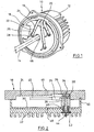
- Fig. 2 is a printed circuit board 30 indicated, which the electrical or electronic components for the so-called power part and the control part of a control device for the motor after Fig. 1 contains. These are not shown in detail and known per se. This includes in particular an inverter and a control device for operating the inverter.
- the printed circuit board 30 is mounted on one side of a heat sink 32.
- a head 34 of the bolt 28 is fixed in the engine shield 18, for example by gluing or other embedding on the side facing away from the engine of the shield 18.
- the bolt 28 extends through the cable lug 26, wherein between the cable lug 26 and motor plate 18 and bolt head 14, a plate spring 36 is arranged is.
- a spacer sleeve 38 is arranged made of electrically conductive material, which is supported on the circuit board 30. The sleeve 38 may additionally be soldered to the circuit board 30 to make electrical contact with the circuit board 30.
- a through hole which is aligned with a through hole in the circuit board 30 and in which a sleeve 40 is inserted from plastic material.
- the sleeve 40 extends into a recess of the spacer sleeve 38 inside, but is not frontally against the bottom of this recess.
- a flange 42 of the sleeve 40 abuts against the facing side of the heat sink 32.
- the bolt 28 has a threaded portion on which a nut 44 is screwed. How finally in Fig. 2 see motor shield 18 and circuit board 30 with heat sink 32 axially aligned openings 46 and 48, respectively, for the passage of the motor shaft 14th
- the plate spring 36 and then a cable lug over the associated pin 28 is placed.
- the engine plate 18 may be previously fixed to the housing 12, which is not shown in detail.
- Printed circuit board with heat sink and soldered sleeve 38 and inserted plastic sleeve 40 are then threaded onto the bolt 28. Subsequently, this arrangement is tightened against the engine plate 18 with the help of nuts. In this way, the control device is fixedly attached to an end face of the motor 10.
- the spring 36 ensures a sufficient bias of the sleeve 38 to the circuit board 30.
- the heat sink 30 is at the edge at 50 against the shield 18 tense and supported.
- Fig. 2 For reasons of illustration, only the connection of a cable 22 to the printed circuit board 30 is shown. It is understood that the connection of all three phase connections takes place in the same way. Also not shown is the connection of the DC power supply to the circuit board 30.
- the two DC cables are led laterally into the space between the printed circuit board 30 and motor plate 18 and electrically connected in a suitable manner with the circuit board 30. It is understood that this connection can be made in the same or similar manner as described in connection with the phase cables 22. This means that the two cables, for example, guided below the cable 22 in the space and also connected by means of bolts and spacers with the circuit board 30 electrically and mechanically.
- the axial through holes of the sleeve 38 and the sleeve 40 are significantly larger in diameter than the diameter of the bolt 28. In this way, tolerances when placing the unit of heat sink 32 and circuit board 30 can be compensated.
Description
- Die Erfindung bezieht sich auf einen Drehstrommotor mit einer mit Gleichstrom gespeiste Steuervorrichtung nach dem Patentanspruch 1.
- Als Antriebe für Aggregate von Flurförderzeugen, beispielsweise Fahrantriebe, Servoantriebe, Pumpenantriebe und dergleichen werden zumeist Drehstrommotoren verwendet. Die Energiequelle ist normalerweise eine Batterie. Es ist daher erforderlich, einen Wechselrichter vorzusehen, der aus Gleichstrom Drehstrom für den Elektromotor erzeugt. Aus diesem Grunde ist dem Elektromotor eine Steuervorrichtung zugeordnet, welche einen Wechselrichter enthält und zugleich einen Steuerteil zur Steuerung des Wechselrichters, damit der Drehstrommotor in seiner Drehzahl gesteuert werden kann.
- Es ist bekannt, eine Steuereinheit in einem getrennten Modul vorzusehen. Die Leistungsanschlüsse befinden sich in einem sogenannten Motorklemmbrett und müssen über zum Teil lange Kabelverbindungen mit der elektrischen Steuereinheit verbunden werden.
- Es ist jedoch auch bereits bekannt, eine Steuereinheit direkt neben dem Motor anzuordnen. Dies hat den Vorteil von Kabelverbindungen reduzierter Länge. Gleichwohl ist auch ein eigenes Gehäuse für die Steuereinheit vorgesehen.
- Aus
DE 101 61 366 A1 ist bekannt geworden, eine Steuereinheit unmittelbar unterhalb eines Motorträgers anzubringen. Die Leistungskontaktierung erfolgt über starre Verbindungselemente, die paßgenau mit der Motoreinheit verbunden werden müssen. Dies ist nur dann möglich, wenn die Phasenanschlüsse eine ausreichende Flexibilität bzw. Biegefähigkeit besitzen, um die Verbindungselemente mit den Statorwicklungen zu verbinden. Im Niederspannungsbereich weisen die Statorwicklungen oft sehr große Querschnitte auf, was eine mechanisch spannungsfreie Verbindung an den entsprechenden Verbindungselementen erschwert. - Weitere Elektromotoren mit Steuervorrichtung sind
DE 4 418 000 A1 undUS 4 668 898 bekannt. - Der Erfindung liegt die Aufgabe zugrunde, einen Elektromotor, zum Beispiel Drehstrommotor mit einer mit Gleichstrom gespeisten Steuervorrichtung zu schaffen, welche sowohl einen mechanischen als auch elektrischen Zusammenbau dieser Teile auf einfache Weise ermöglicht.
- Diese Aufgabe wird erfindungsgemäß durch die Merkmale des Patentanspruchs 1 gelöst.
- Bei der Erfindung ist die Leiterplatte an der Außenseite eines Motorschildes aus thermisch beständigem und elektrisch isolierendem Material befestigt. Bekanntlich weist ein Elektromotor ein Motorschild auf, der üblicherweise an der offenen Stirnseite des Gehäuses angebracht ist. Er ist im Erfindungsfalle aus einem hoch wärmebeständigen und elektrisch isolierenden Material, vorzugsweise einem geeigneten Kunststoff, hergestellt. Es reicht unter Umständen aus, nur den Abschnitt des Motorschildes aus isolierendem Material vorzusehen, der in unmittelbarer Nähe zu den Anschlußkontakten und/oder den Phasenleitern liegt. Bei der Erfindung werden ferner isolierte Phasenanschlüsse durch mindestens eine Öffnung des Motorschildes in einen Zwischenraum zwischen Motorschild und Leiterplatte geführt. Über Anschlußkontakte werden die Phasenanschlüsse mit der Leiterplatte elektrisch verbunden. Schließlich sind Befestigungsmittel für die Befestigung der Leiterplatte am Motorschild vorgesehen.
- Mit der Erfindung wird eine Reihe von Vorteilen erzielt. Die elektrische Verbindung zwischen dem Stator des Motors und der Leiterplatte, welche die Steuereinheit für den Motor bildet, ist kurz. Neben der Einsparung an Material wird auch eine verbesserte EMV-Eigenschaft aufgrund der kurzen Verbindungen erzielt. Das Motorschild erlaubt eine thermisch und elektrisch isolierte Anbindung der Phasenkontakte. Vor allen Dingen sind Motor und Steuervorrichtung in einem gemeinsamen Gehäuse integriert. Auf das übliche Anschlußklemmbrett kann verzichtet werden. Darüber hinaus ermöglicht die Erfindung eine unkomplizierte Montage der Steuervorrichtung am Motorgehäuse.
- Nach einer Ausgestaltung der Erfindung ist die Leiterplatte an der Innenseite eines Kühlkörpers angebracht, der seinerseits von den Befestigungsmitteln gegen das Motorschild gespannt ist. Im Leistungsteil der Steuervorrichtung, die auf der Leiterplatte angebracht ist, findet eine nicht unerhebliche Wärmeentwicklung statt, die abgeführt werden muß. Hierzu dient, wie an sich bekannt, ein Kühlkörper. Der Kühlkörper dient dabei zugleich der Befestigung der Leiterplatte an dem Motorschild. Dabei kann der Kühlkörper auch unmittelbar mit der Stirnseite des Motorgehäuses verbunden werden.
- Nach einer weiteren Ausgestaltung der Erfindung kann das Motorschild auf der dem Stator abgewandten Seite Vertiefungen oder Ausnehmungen aufweisen, in welchen die Phasenanschlüsse versenkt geführt sind. Die Phasenanschlüsse können nach einer weiteren Ausgestaltung der Erfindung Kabelschuhe aufweisen, welche am Motorschild festgelegt werden. Die Kabelschuhe werden über ein geeignetes Verbindungsteil mit der Leiterplatte in Kontakt gebracht. Das Verbindungsteil kann zum Beispiel auch an der Leiterplatte verlötet werden. Vorzugsweise ist das Verbindungsteil ein elektrisch leitender Abstandskörper, der zwischen einem Kabelschuh und der Leiterplatte geklemmt ist.
- Zur Befestigung der Leiterplatte bzw. des Kühlkörpers kann nach einer weiteren Ausgestaltung der Erfindung am Motorschild das eine Ende von mehreren Bolzen festgelegt werden, die sich isoliert durch die Leiterplatte erstrecken. Das andere Ende der Bolzen ist mit einem Gewindeabschnitt versehen, auf den eine Mutter aufschraubbar ist zur Befestigung der Leiterplatte bzw. des Kühlkörpers am Motorschild. Vorzugsweise erstrecken sich drei Bolzen jeweils durch eine axiale Durchbohrung eines der Abstandskörper. Dadurch wird die Kontaktierung der Leistungskontakte auf der Leiterplatte neben einer Lötverbindung zusätzlich durch eine Schraubverbindung unterstützt. Die Kontaktierung der Phasenanschlüsse erfolgt weitgehend mechanisch spannungsfrei. Außerdem dienen die Leistungskontakte zur Fixierung und/oder Abstützung der Steuervorrichtung am Motorschild.
- Ein Ausführungsbeispiel der Erfindung wird nachfolgend anhand von Zeichnungen näher erläutert.
- Fig. 1
- zeigt perspektivisch eine Stirnansicht eines Drehstrommotors mit einem Motorschild nach der Erfindung.
- Fig. 2
- zeigt den Motorschild nach
Fig. 1 mit daran angebrachter Leiterplatte. - In
Fig. 1 ist ein Drehstrommotor 10 dargestellt, der ein Gehäuse 12 aufweist. Stator und Läufer des Drehstrommotors, zum Beispiel Kurzschlußläufermotor, sind nicht zu erkennen. Man erkennt hingegen die Motorwelle 14, die mit einem geeigneten anzutreibenden Aggregat gekoppelt ist. Ein solches Aggregat kann zum Beispiel eine Pumpe oder ein Getriebe sein. Diese Teile können unmittelbar an die offene Stirnseite des Motors 10 angeflanscht werden, wofür das Gehäuse 12 geeignete radiale Ansätze 16 mit Löchern aufweist. Für die nachfolgende Betrachtung ist dies jedoch nicht von Bedeutung. - Die Motorwelle erstreckt sich durch eine kreisförmige Platte oder Scheibe 18 hindurch, die das Motorschild bildet. Das Motorschild 18 ist aus einem geeigneten thermisch hochfesten elektrisch isolierenden Kunststoffmaterial geformt. Das Motorschild 18 weist nahe dem Rand einen länglichen Schlitz 20 auf, durch den sich hindurch drei Kabel 22 erstrecken. Sie sind die Phasenanschlüsse für die nicht gezeigte Statorwicklung. Wie in
Fig. 1 ferner erkennbar, sind die Kabel 22 in länglichen Vertiefungen 24 auf der dem Stator abgewandten Seite des Motorschildes 18 angeordnet. An den Enden weisen sie jeweils einen Kabelschuh 26 auf. Durch die Kabelschuhe 26 erstreckt sich jeweils ein Bolzen 28. - Der Motor kann in der gezeigten Weise vom Motorhersteller erstellt und geliefert werden. Zur Steuerung des Motors ist eine Steuervorrichtung erforderlich, die anhand von
Fig. 2 erläutert wird. InFig. 2 ist eine Leiterplatte 30 angedeutet, welche die elektrischen bzw. elektronischen Bauteile für den sogenannten Leistungsteil und den Steuerteil einer Steuervorrichtung für den Motor nachFig. 1 enthält. Diese sind im einzelnen nicht dargestellt und an sich bekannt. Hierzu gehört insbesondere ein Wechselrichter sowie eine Steuervorrichtung zum Betrieb des Wechselrichters. Die Leiterplatte 30 ist auf der einen Seite eines Kühlkörpers 32 angebracht. InFig. 2 ist ferner zu erkennen, daß ein Kopf 34 des Bolzens 28 in dem Motorschild 18 festgelegt ist, beispielsweise durch Verklebung oder sonstige Einbettung auf der dem Motor abgewandten Seite des Schildes 18. Wie ferner erkennbar, erstreckt sich der Bolzen 28 durch den Kabelschuh 26, wobei zwischen Kabelschuh 26 und Motorschild 18 bzw. Bolzenkopf 14 eine Tellerfeder 36 angeordnet ist. Zwischen dem Kabelschuh 26 und der Leiterplatte 30 ist eine Abstandshülse 38 aus elektrisch leitendem Material angeordnet, die sich auf der Leiterplatte 30 abstützt. Die Hülse 38 kann zusätzlich mit der Leiterplatte 30 verlötet werden, um einen elektrischen Kontakt zur Leiterplatte 30 herzustellen. - In dem Kühlkörper 32 befindet sich eine Durchbohrung, die mit einer Durchbohrung in der Leiterplatte 30 ausgerichtet ist und in welche hinein eine Hülse 40 aus Kunststoffmaterial eingesetzt ist. Die Hülse 40 erstreckt sich in eine Ausnehmung der Abstandshülse 38 hinein, liegt jedoch stirnseitig nicht gegen den Boden dieser Ausnehmung. Ein Flansch 42 der Hülse 40 liegt gegen die zugekehrte Seite des Kühlkörpers 32 an. Der Bolzen 28 hat einen Gewindeabschnitt, auf den eine Mutter 44 aufschraubbar ist. Wie schließlich in
Fig. 2 zu sehen, weisen Motorschild 18 und Leiterplatte 30 mit Kühlkörper 32 axial ausgerichtete Öffnungen 46 bzw. 48 auf für die Hindurchführung der Motorwelle 14. - Bei der Montage der Anordnungen nach
Fig. 1 und 2 wird zunächst die Tellerfeder 36 und dann ein Kabelschuh über den zugeordneten Bolzen 28 gelegt. Das Motorschild 18 kann bereits vorher mit dem Gehäuse 12 fest verbunden werden, was im einzelnen nicht dargestellt ist. Leiterplatte mit Kühlkörper und aufgelötete Hülse 38 und eingesetzte Kunststoffhülse 40 werden anschließend auf die Bolzen 28 aufgefädelt. Anschließend wird mit Hilfe der Muttern diese Anordnung gegen das Motorschild 18 gespannt. Auf diese Weise ist die Steuervorrichtung fest an einer Stirnseite des Motors 10 befestigt. Die Feder 36 sorgt für eine ausreichende Vorspannung der Hülse 38 an der Leiterplatte 30. Der Kühlkörper 30 ist dabei am Rand bei 50 gegen das Schild 18 angespannt und abgestützt. - In
Fig. 2 ist aus Darstellungsgründen nur die Verbindung eines Kabels 22 mit der Leiterplatte 30 dargestellt. Es versteht sich, daß die Verbindung aller drei Phasenanschlüsse in gleicher Weise erfolgt. Ebenfalls nicht dargestellt ist die Verbindung der Gleichstromeinspeisung zur Leiterplatte 30. Zu diesem Zwecke können die beiden Gleichstromkabel seitlich in den Zwischenraum zwischen Leiterplatte 30 und Motorschild 18 hineingeführt und in geeigneter Weise mit der Leiterplatte 30 elektrisch verbunden werden. Es versteht sich, daß diese Verbindung in gleicher oder ähnlicher Weise erfolgen kann wie dies in Verbindung mit den Phasenkabeln 22 beschrieben ist. Dies bedeutet, daß die beiden Kabel zum Beispiel unterhalb der Kabel 22 in den Zwischenraum geführt und ebenfalls mit Hilfe von Bolzen und Abstandskörpern mit der Leiterplatte 30 elektrisch und mechanisch verbunden werden. - Die axialen Durchbohrungen der Hülse 38 und der Hülse 40 sind im Durchmesser deutlich größer als der Durchmesser der Bolzen 28. Auf diese Weise können Toleranzen beim Aufsetzen der Einheit aus Kühlkörper 32 und Leiterplatte 30 ausgeglichen werden.
Claims (10)
- Drehstrommotor mit einer mit Gleichstrom gespeisten Steuervorrichtung, wobei die Steuervorrichtung eine Leiterplatte (30) mit Leistungs- und Steuerteil enthält, die am Gehäuse des Motors angebracht ist, wobei Phasenanschlüsse (22) des Motors und einer Gleichstromquelle über Anschlusskontakte mit der Leiterplatte (30) elektrisch verbunden sind, wobei die Leiterplatte (30) an der Außenseite eines Motorschilds (18) befestigbar ist und die isolierten Phasenanschlüsse (22) durch mindestens eine Öffnung (20) des Motorschilds (18) in einen Zwischenraum zur Leiterplatte (30) hin geführt und über Anschlusskontakte mit der Leiterplatte (30) elektrisch verbunden sind und wobei Befestigungsmittel für die Befestigung der Leiterplatte (30) vorgesehe sind, dadurch gekennzeichnet, dass der Motorschild (18) zumindest im Bereich der Phasenanschlüsse (22) bezienungsweise der Anschluss kontakte aus thermisch beständigem und elektrisch isolierendem Material besteht, die Leiterplatte (30) unmittelbar am Motorschild (18) über die Befestigungsmittel befestigbar ist und die isolierten Phasenanschlüsse in den Zwischenraum zwischen dem Motorschild (18) und der Leiterplatte (30) geführt sind.
- Drehstrommotor nach Anspruch 1, dadurch gekennzeichnet, dass die Leiterplatte (30) an der Innenseite eines Kühlkörpers (32) angebracht ist, der seinerseits mit der Leiterplatte (30) von den Befestigungsmitteln gegen den Motorschild (18) gespannt ist.
- Drehstrommotor nach Anspruch 1 oder 2, dadurch gekennzeichnet, dass die isolierten Phasenanschlüsse (22) über eine einzige Öffnung (20) im Motorschild (18) geführt sind.
- Drehstrommotor nach einem der Ansprüche 1 bis 3, dadurch gekennzeichnet, dass die isolierten Phasenanschlüsse (22) in Ausnehmungen (24) an der Außenseite des Motorschildes (18) verlaufen.
- Drehstrommotor nach einem der Ansprüche 1 bis 4, dadurch gekennzeichnet, dass Kabelschuhe (26) der Phasenanschlüsse (22) am Motorschild (18) festgelegt sind und über ein elektrisches Verbindungsteil mit der Leiterplatte (30) in Kontakt stehen.
- Drehstrommotor nach Anspruch 5, dadurch gekennzeichnet, dass das Verbindungsteil ein elektrisch leitender Abstandskörper (38) ist, der zwischen einem Kabelschuh (26) und der Leiterplatte (10) gespannt ist.
- Drehstrommotor nach einem der Ansprüche 1 bis 6, dadurch gekennzeichnet, dass am Motorschild (18) das eine Ende (34) von mehreren Bolzen (28) festgelegt ist, die sich isoliert durch die Leiterplatte (30) erstrecken und das andere Ende der Bolzen (28) einen Gewindeabschnitt aufweist, auf den eine Mutter (44) aufschraubbar ist zur Festlegung der Leiterplatte (30) bzw. des Kühlkörpers (32) am Motorschild (18).
- Drehstrommotor nach Anspruch 6 und 7, dadurch gekennzeichnet, dass drei Bolzen (28) sich jeweils durch eine axiale Durchbohrung des Abstandkörpers (38) erstrecken.
- Drehstrommotor nach Anspruch 7 oder 8, dadurch gekennzeichnet, dass in Bohrungen der Leiterplatte (30) und des Kühlkörpers (32) eine Hülse (40) aus Isoliermaterial eingesetzt ist, durch welche sich jeweils ein Bolzen (28) erstreckt.
- Drehstrommotor nach einem der Ansprüche 5 bis 9, dadurch gekennzeichnet, dass zwischen dem Motorschild (18) und den Kabelschuhen (26) jeweils eine Feder (36), vorzugsweise Tellerfeder, angeordnet ist.
Applications Claiming Priority (1)
| Application Number | Priority Date | Filing Date | Title |
|---|---|---|---|
| DE102006052583A DE102006052583A1 (de) | 2006-11-08 | 2006-11-08 | Drehstrommotor und Steuervorrichtung |
Publications (3)
| Publication Number | Publication Date |
|---|---|
| EP1921733A2 EP1921733A2 (de) | 2008-05-14 |
| EP1921733A3 EP1921733A3 (de) | 2008-08-20 |
| EP1921733B1 true EP1921733B1 (de) | 2010-10-06 |
Family
ID=39092149
Family Applications (1)
| Application Number | Title | Priority Date | Filing Date |
|---|---|---|---|
| EP07019994A Revoked EP1921733B1 (de) | 2006-11-08 | 2007-10-12 | Drehstrommotor und Steuervorrichtung |
Country Status (3)
| Country | Link |
|---|---|
| EP (1) | EP1921733B1 (de) |
| CN (1) | CN101222164B (de) |
| DE (2) | DE102006052583A1 (de) |
Families Citing this family (4)
| Publication number | Priority date | Publication date | Assignee | Title |
|---|---|---|---|---|
| DE102016106104A1 (de) * | 2016-04-04 | 2017-10-05 | Linde Material Handling Gmbh | Elektrische Motoreinheit für mobile Arbeitsmaschine |
| DE102018124289A1 (de) * | 2018-10-02 | 2020-04-02 | Minebea Mitsumi Inc. | Elektromotor mit Leiterplatte zur elektrischen Kontaktierung der Motorwicklungen |
| EP4181364A1 (de) * | 2019-12-06 | 2023-05-17 | Zhuhai Enpower Electric Co., Ltd. | Motorsteuerung mit ringschaltungslayout, antriebsanordnung und fahrzeug |
| EP4277093A1 (de) * | 2022-05-11 | 2023-11-15 | Siemens Aktiengesellschaft | Geschweisste hochstromverbindungen in dynamoelektrischen maschinen |
Family Cites Families (11)
| Publication number | Priority date | Publication date | Assignee | Title |
|---|---|---|---|---|
| US4593163A (en) * | 1983-08-12 | 1986-06-03 | General Electric Company | Electric motors and method of manufacturing and operating same |
| DE8602197U1 (de) * | 1986-01-29 | 1988-11-17 | Hanning Elektro-Werke Gmbh & Co, 4811 Oerlinghausen, De | |
| US4668898A (en) * | 1986-04-21 | 1987-05-26 | General Electric Company | Electronically commutated motor |
| DE3939738A1 (de) * | 1989-12-01 | 1991-06-06 | Telefunken Electronic Gmbh | Elektromotor mit einem luefterrad zum ansaugen von kuehlluft fuer kraftfahrzeuge |
| FR2689322B1 (fr) * | 1992-03-24 | 1994-05-13 | Valeo Equipements Elect Moteur | Dispositif a borne de prise de courant pour alternateur de vehicule automobile. |
| DE4418000C2 (de) * | 1994-05-21 | 1998-03-19 | Fhp Motors Gmbh | Elektronisch gesteuerter Elektromotor, insbesondere mit einem Lüfterrad zum Ansaugen von Kühlluft für Kraftfahrzeuge |
| JP3513338B2 (ja) * | 1996-10-09 | 2004-03-31 | 三菱電機株式会社 | 可変速電動機 |
| IT1289749B1 (it) * | 1996-12-13 | 1998-10-16 | Fiat Auto Spa | Sistema per collegare con angolazione prefissata un cavo elettrico a un morsetto di una apparecchiatura elettrica, in particolare un |
| US20020047488A1 (en) * | 1999-11-01 | 2002-04-25 | Scot Adams Webb | Powder coated insulated bolts |
| US6864616B2 (en) * | 2001-10-09 | 2005-03-08 | General Electric Company | Method and apparatus for forming an electric motor having stacked laminations |
| DE10161366A1 (de) * | 2001-12-14 | 2003-06-26 | Temic Auto Electr Motors Gmbh | Elektrische Antriebseinheit |
-
2006
- 2006-11-08 DE DE102006052583A patent/DE102006052583A1/de not_active Withdrawn
-
2007
- 2007-10-12 EP EP07019994A patent/EP1921733B1/de not_active Revoked
- 2007-10-12 DE DE502007005258T patent/DE502007005258D1/de active Active
- 2007-11-02 CN CN200710169217.5A patent/CN101222164B/zh not_active Expired - Fee Related
Also Published As
| Publication number | Publication date |
|---|---|
| DE502007005258D1 (de) | 2010-11-18 |
| CN101222164B (zh) | 2015-07-01 |
| CN101222164A (zh) | 2008-07-16 |
| EP1921733A2 (de) | 2008-05-14 |
| EP1921733A3 (de) | 2008-08-20 |
| DE102006052583A1 (de) | 2008-05-15 |
Similar Documents
| Publication | Publication Date | Title |
|---|---|---|
| EP1532723B1 (de) | Anordnung zur unterbringung der leistungs- und steuerelektronik eines elektromotors | |
| EP2453560B1 (de) | Pumpenaggregat | |
| EP2320092B1 (de) | Pumpenaggregat | |
| DE102006034991B4 (de) | Elektrische Servolenkungsvorrichtung | |
| DE3842588C2 (de) | ||
| DE60128530T2 (de) | Einbau einer Steuerelektronik für bürstenlose Gleichstrommotoren in ihren Kühlkörper | |
| DE112017001202T5 (de) | Elektrische Antriebsvorrichtung und elektrische Servolenkvorrichtung | |
| EP1675249B1 (de) | Elektromotor | |
| EP1023759A1 (de) | Elektromotor, insbesondere mit einem lüfterrad zur bildung eines axial- oder radiallüfters | |
| DE102005060282A1 (de) | Elektrische Servolenkungseinrichtung | |
| DE102016107079A1 (de) | Motorantriebssteuerung für ein Fahrzeug | |
| DE102008059947A1 (de) | Batterie mit einer in einem Batteriegehäuse angeordneten Wärmeleitplatte und daran direkt montierten elektronischen Bauelementen zum Temperieren der Batterie | |
| EP0368142B1 (de) | Elektronisches Steuergerät | |
| EP2909923A1 (de) | Anschlusselement für eine antriebsanordnung sowie eine antriebsanordnung mit einem anschlussteil | |
| EP1921733B1 (de) | Drehstrommotor und Steuervorrichtung | |
| EP2716145B1 (de) | Leiterplatte für elektrische bauelemente und leiterplattensystem | |
| EP2750267A1 (de) | Pumpenaggregat | |
| DE10010439C2 (de) | Stellantrieb bzw. Verfahren zur Montage eines Stellantriebs | |
| DE102007014645A1 (de) | Elektrische Baugruppe, insbesondere für eine Lenkhilfe eines Kraftfahrzeuges | |
| EP2188839A1 (de) | Elektrogerät und antrieb | |
| DE102017002865A1 (de) | Aufbau eines Axiallüfters | |
| DE102004027653B4 (de) | Elektromotor | |
| EP1665501B1 (de) | Elektromotor | |
| WO2015032993A1 (de) | Leiterplattenanordnung, verfahren zum herstellen einer leiterplattenanordnung und kühlerlüftermodul | |
| DE4232929A1 (de) | Drehstromgenerator mit Gleichrichter |
Legal Events
| Date | Code | Title | Description |
|---|---|---|---|
| PUAI | Public reference made under article 153(3) epc to a published international application that has entered the european phase |
Free format text: ORIGINAL CODE: 0009012 |
|
| AK | Designated contracting states |
Kind code of ref document: A2 Designated state(s): AT BE BG CH CY CZ DE DK EE ES FI FR GB GR HU IE IS IT LI LT LU LV MC MT NL PL PT RO SE SI SK TR |
|
| AX | Request for extension of the european patent |
Extension state: AL BA HR MK RS |
|
| PUAL | Search report despatched |
Free format text: ORIGINAL CODE: 0009013 |
|
| AK | Designated contracting states |
Kind code of ref document: A3 Designated state(s): AT BE BG CH CY CZ DE DK EE ES FI FR GB GR HU IE IS IT LI LT LU LV MC MT NL PL PT RO SE SI SK TR |
|
| AX | Request for extension of the european patent |
Extension state: AL BA HR MK RS |
|
| 17P | Request for examination filed |
Effective date: 20080904 |
|
| AKX | Designation fees paid |
Designated state(s): CZ DE FR GB |
|
| GRAP | Despatch of communication of intention to grant a patent |
Free format text: ORIGINAL CODE: EPIDOSNIGR1 |
|
| GRAS | Grant fee paid |
Free format text: ORIGINAL CODE: EPIDOSNIGR3 |
|
| GRAA | (expected) grant |
Free format text: ORIGINAL CODE: 0009210 |
|
| AK | Designated contracting states |
Kind code of ref document: B1 Designated state(s): CZ DE FR GB |
|
| REG | Reference to a national code |
Ref country code: GB Ref legal event code: FG4D Free format text: NOT ENGLISH |
|
| REF | Corresponds to: |
Ref document number: 502007005258 Country of ref document: DE Date of ref document: 20101118 Kind code of ref document: P |
|
| PLBI | Opposition filed |
Free format text: ORIGINAL CODE: 0009260 |
|
| PG25 | Lapsed in a contracting state [announced via postgrant information from national office to epo] |
Ref country code: CZ Free format text: LAPSE BECAUSE OF NON-PAYMENT OF DUE FEES Effective date: 20101012 |
|
| PLAX | Notice of opposition and request to file observation + time limit sent |
Free format text: ORIGINAL CODE: EPIDOSNOBS2 |
|
| 26 | Opposition filed |
Opponent name: STILL GMBH Effective date: 20110706 |
|
| REG | Reference to a national code |
Ref country code: DE Ref legal event code: R026 Ref document number: 502007005258 Country of ref document: DE Effective date: 20110706 |
|
| PLAF | Information modified related to communication of a notice of opposition and request to file observations + time limit |
Free format text: ORIGINAL CODE: EPIDOSCOBS2 |
|
| PLBB | Reply of patent proprietor to notice(s) of opposition received |
Free format text: ORIGINAL CODE: EPIDOSNOBS3 |
|
| PLAY | Examination report in opposition despatched + time limit |
Free format text: ORIGINAL CODE: EPIDOSNORE2 |
|
| REG | Reference to a national code |
Ref country code: FR Ref legal event code: PLFP Year of fee payment: 9 |
|
| PLAH | Information related to despatch of examination report in opposition + time limit modified |
Free format text: ORIGINAL CODE: EPIDOSCORE2 |
|
| PLAL | Information related to reply to examination report in opposition modified |
Free format text: ORIGINAL CODE: EPIDOSCORE3 |
|
| PLBC | Reply to examination report in opposition received |
Free format text: ORIGINAL CODE: EPIDOSNORE3 |
|
| PLAY | Examination report in opposition despatched + time limit |
Free format text: ORIGINAL CODE: EPIDOSNORE2 |
|
| PLAH | Information related to despatch of examination report in opposition + time limit modified |
Free format text: ORIGINAL CODE: EPIDOSCORE2 |
|
| REG | Reference to a national code |
Ref country code: FR Ref legal event code: PLFP Year of fee payment: 10 |
|
| PLBC | Reply to examination report in opposition received |
Free format text: ORIGINAL CODE: EPIDOSNORE3 |
|
| PLAB | Opposition data, opponent's data or that of the opponent's representative modified |
Free format text: ORIGINAL CODE: 0009299OPPO |
|
| R26 | Opposition filed (corrected) |
Opponent name: STILL GMBH Effective date: 20110706 |
|
| REG | Reference to a national code |
Ref country code: FR Ref legal event code: PLFP Year of fee payment: 11 |
|
| REG | Reference to a national code |
Ref country code: DE Ref legal event code: R064 Ref document number: 502007005258 Country of ref document: DE Ref country code: DE Ref legal event code: R103 Ref document number: 502007005258 Country of ref document: DE |
|
| RDAF | Communication despatched that patent is revoked |
Free format text: ORIGINAL CODE: EPIDOSNREV1 |
|
| STAA | Information on the status of an ep patent application or granted ep patent |
Free format text: STATUS: THE PATENT HAS BEEN GRANTED |
|
| PGFP | Annual fee paid to national office [announced via postgrant information from national office to epo] |
Ref country code: CZ Payment date: 20171011 Year of fee payment: 11 Ref country code: FR Payment date: 20171031 Year of fee payment: 11 |
|
| PGFP | Annual fee paid to national office [announced via postgrant information from national office to epo] |
Ref country code: GB Payment date: 20171101 Year of fee payment: 11 |
|
| PGFP | Annual fee paid to national office [announced via postgrant information from national office to epo] |
Ref country code: DE Payment date: 20171229 Year of fee payment: 11 |
|
| RDAG | Patent revoked |
Free format text: ORIGINAL CODE: 0009271 |
|
| STAA | Information on the status of an ep patent application or granted ep patent |
Free format text: STATUS: PATENT REVOKED |
|
| 27W | Patent revoked |
Effective date: 20171214 |
|
| GBPR | Gb: patent revoked under art. 102 of the ep convention designating the uk as contracting state |
Effective date: 20171214 |