EP0948946A1 - Dispositif pour la mise en place d'une prothèse intraluminable - Google Patents
Dispositif pour la mise en place d'une prothèse intraluminable Download PDFInfo
- Publication number
- EP0948946A1 EP0948946A1 EP99113203A EP99113203A EP0948946A1 EP 0948946 A1 EP0948946 A1 EP 0948946A1 EP 99113203 A EP99113203 A EP 99113203A EP 99113203 A EP99113203 A EP 99113203A EP 0948946 A1 EP0948946 A1 EP 0948946A1
- Authority
- EP
- European Patent Office
- Prior art keywords
- prosthesis
- sheath
- shaft
- delivery catheter
- distal end
- Prior art date
- Legal status (The legal status is an assumption and is not a legal conclusion. Google has not performed a legal analysis and makes no representation as to the accuracy of the status listed.)
- Withdrawn
Links
Images


Classifications
-
- A—HUMAN NECESSITIES
- A61—MEDICAL OR VETERINARY SCIENCE; HYGIENE
- A61F—FILTERS IMPLANTABLE INTO BLOOD VESSELS; PROSTHESES; DEVICES PROVIDING PATENCY TO, OR PREVENTING COLLAPSING OF, TUBULAR STRUCTURES OF THE BODY, e.g. STENTS; ORTHOPAEDIC, NURSING OR CONTRACEPTIVE DEVICES; FOMENTATION; TREATMENT OR PROTECTION OF EYES OR EARS; BANDAGES, DRESSINGS OR ABSORBENT PADS; FIRST-AID KITS
- A61F2/00—Filters implantable into blood vessels; Prostheses, i.e. artificial substitutes or replacements for parts of the body; Appliances for connecting them with the body; Devices providing patency to, or preventing collapsing of, tubular structures of the body, e.g. stents
- A61F2/02—Prostheses implantable into the body
- A61F2/04—Hollow or tubular parts of organs, e.g. bladders, tracheae, bronchi or bile ducts
- A61F2/06—Blood vessels
- A61F2/07—Stent-grafts
-
- A—HUMAN NECESSITIES
- A61—MEDICAL OR VETERINARY SCIENCE; HYGIENE
- A61F—FILTERS IMPLANTABLE INTO BLOOD VESSELS; PROSTHESES; DEVICES PROVIDING PATENCY TO, OR PREVENTING COLLAPSING OF, TUBULAR STRUCTURES OF THE BODY, e.g. STENTS; ORTHOPAEDIC, NURSING OR CONTRACEPTIVE DEVICES; FOMENTATION; TREATMENT OR PROTECTION OF EYES OR EARS; BANDAGES, DRESSINGS OR ABSORBENT PADS; FIRST-AID KITS
- A61F2/00—Filters implantable into blood vessels; Prostheses, i.e. artificial substitutes or replacements for parts of the body; Appliances for connecting them with the body; Devices providing patency to, or preventing collapsing of, tubular structures of the body, e.g. stents
- A61F2/82—Devices providing patency to, or preventing collapsing of, tubular structures of the body, e.g. stents
- A61F2/86—Stents in a form characterised by the wire-like elements; Stents in the form characterised by a net-like or mesh-like structure
- A61F2/90—Stents in a form characterised by the wire-like elements; Stents in the form characterised by a net-like or mesh-like structure characterised by a net-like or mesh-like structure
- A61F2/91—Stents in a form characterised by the wire-like elements; Stents in the form characterised by a net-like or mesh-like structure characterised by a net-like or mesh-like structure made from perforated sheet material or tubes, e.g. perforated by laser cuts or etched holes
- A61F2/915—Stents in a form characterised by the wire-like elements; Stents in the form characterised by a net-like or mesh-like structure characterised by a net-like or mesh-like structure made from perforated sheet material or tubes, e.g. perforated by laser cuts or etched holes with bands having a meander structure, adjacent bands being connected to each other
-
- A—HUMAN NECESSITIES
- A61—MEDICAL OR VETERINARY SCIENCE; HYGIENE
- A61F—FILTERS IMPLANTABLE INTO BLOOD VESSELS; PROSTHESES; DEVICES PROVIDING PATENCY TO, OR PREVENTING COLLAPSING OF, TUBULAR STRUCTURES OF THE BODY, e.g. STENTS; ORTHOPAEDIC, NURSING OR CONTRACEPTIVE DEVICES; FOMENTATION; TREATMENT OR PROTECTION OF EYES OR EARS; BANDAGES, DRESSINGS OR ABSORBENT PADS; FIRST-AID KITS
- A61F2/00—Filters implantable into blood vessels; Prostheses, i.e. artificial substitutes or replacements for parts of the body; Appliances for connecting them with the body; Devices providing patency to, or preventing collapsing of, tubular structures of the body, e.g. stents
- A61F2/95—Instruments specially adapted for placement or removal of stents or stent-grafts
- A61F2/9517—Instruments specially adapted for placement or removal of stents or stent-grafts handle assemblies therefor
-
- A—HUMAN NECESSITIES
- A61—MEDICAL OR VETERINARY SCIENCE; HYGIENE
- A61F—FILTERS IMPLANTABLE INTO BLOOD VESSELS; PROSTHESES; DEVICES PROVIDING PATENCY TO, OR PREVENTING COLLAPSING OF, TUBULAR STRUCTURES OF THE BODY, e.g. STENTS; ORTHOPAEDIC, NURSING OR CONTRACEPTIVE DEVICES; FOMENTATION; TREATMENT OR PROTECTION OF EYES OR EARS; BANDAGES, DRESSINGS OR ABSORBENT PADS; FIRST-AID KITS
- A61F2/00—Filters implantable into blood vessels; Prostheses, i.e. artificial substitutes or replacements for parts of the body; Appliances for connecting them with the body; Devices providing patency to, or preventing collapsing of, tubular structures of the body, e.g. stents
- A61F2/95—Instruments specially adapted for placement or removal of stents or stent-grafts
- A61F2/954—Instruments specially adapted for placement or removal of stents or stent-grafts for placing stents or stent-grafts in a bifurcation
-
- A—HUMAN NECESSITIES
- A61—MEDICAL OR VETERINARY SCIENCE; HYGIENE
- A61F—FILTERS IMPLANTABLE INTO BLOOD VESSELS; PROSTHESES; DEVICES PROVIDING PATENCY TO, OR PREVENTING COLLAPSING OF, TUBULAR STRUCTURES OF THE BODY, e.g. STENTS; ORTHOPAEDIC, NURSING OR CONTRACEPTIVE DEVICES; FOMENTATION; TREATMENT OR PROTECTION OF EYES OR EARS; BANDAGES, DRESSINGS OR ABSORBENT PADS; FIRST-AID KITS
- A61F2/00—Filters implantable into blood vessels; Prostheses, i.e. artificial substitutes or replacements for parts of the body; Appliances for connecting them with the body; Devices providing patency to, or preventing collapsing of, tubular structures of the body, e.g. stents
- A61F2/95—Instruments specially adapted for placement or removal of stents or stent-grafts
- A61F2/962—Instruments specially adapted for placement or removal of stents or stent-grafts having an outer sleeve
- A61F2/97—Instruments specially adapted for placement or removal of stents or stent-grafts having an outer sleeve the outer sleeve being splittable
-
- A—HUMAN NECESSITIES
- A61—MEDICAL OR VETERINARY SCIENCE; HYGIENE
- A61F—FILTERS IMPLANTABLE INTO BLOOD VESSELS; PROSTHESES; DEVICES PROVIDING PATENCY TO, OR PREVENTING COLLAPSING OF, TUBULAR STRUCTURES OF THE BODY, e.g. STENTS; ORTHOPAEDIC, NURSING OR CONTRACEPTIVE DEVICES; FOMENTATION; TREATMENT OR PROTECTION OF EYES OR EARS; BANDAGES, DRESSINGS OR ABSORBENT PADS; FIRST-AID KITS
- A61F2/00—Filters implantable into blood vessels; Prostheses, i.e. artificial substitutes or replacements for parts of the body; Appliances for connecting them with the body; Devices providing patency to, or preventing collapsing of, tubular structures of the body, e.g. stents
- A61F2/0095—Packages or dispensers for prostheses or other implants
-
- A—HUMAN NECESSITIES
- A61—MEDICAL OR VETERINARY SCIENCE; HYGIENE
- A61F—FILTERS IMPLANTABLE INTO BLOOD VESSELS; PROSTHESES; DEVICES PROVIDING PATENCY TO, OR PREVENTING COLLAPSING OF, TUBULAR STRUCTURES OF THE BODY, e.g. STENTS; ORTHOPAEDIC, NURSING OR CONTRACEPTIVE DEVICES; FOMENTATION; TREATMENT OR PROTECTION OF EYES OR EARS; BANDAGES, DRESSINGS OR ABSORBENT PADS; FIRST-AID KITS
- A61F2/00—Filters implantable into blood vessels; Prostheses, i.e. artificial substitutes or replacements for parts of the body; Appliances for connecting them with the body; Devices providing patency to, or preventing collapsing of, tubular structures of the body, e.g. stents
- A61F2/82—Devices providing patency to, or preventing collapsing of, tubular structures of the body, e.g. stents
- A61F2/848—Devices providing patency to, or preventing collapsing of, tubular structures of the body, e.g. stents having means for fixation to the vessel wall, e.g. barbs
-
- A—HUMAN NECESSITIES
- A61—MEDICAL OR VETERINARY SCIENCE; HYGIENE
- A61F—FILTERS IMPLANTABLE INTO BLOOD VESSELS; PROSTHESES; DEVICES PROVIDING PATENCY TO, OR PREVENTING COLLAPSING OF, TUBULAR STRUCTURES OF THE BODY, e.g. STENTS; ORTHOPAEDIC, NURSING OR CONTRACEPTIVE DEVICES; FOMENTATION; TREATMENT OR PROTECTION OF EYES OR EARS; BANDAGES, DRESSINGS OR ABSORBENT PADS; FIRST-AID KITS
- A61F2/00—Filters implantable into blood vessels; Prostheses, i.e. artificial substitutes or replacements for parts of the body; Appliances for connecting them with the body; Devices providing patency to, or preventing collapsing of, tubular structures of the body, e.g. stents
- A61F2/82—Devices providing patency to, or preventing collapsing of, tubular structures of the body, e.g. stents
- A61F2/86—Stents in a form characterised by the wire-like elements; Stents in the form characterised by a net-like or mesh-like structure
- A61F2/89—Stents in a form characterised by the wire-like elements; Stents in the form characterised by a net-like or mesh-like structure the wire-like elements comprising two or more adjacent rings flexibly connected by separate members
-
- A—HUMAN NECESSITIES
- A61—MEDICAL OR VETERINARY SCIENCE; HYGIENE
- A61F—FILTERS IMPLANTABLE INTO BLOOD VESSELS; PROSTHESES; DEVICES PROVIDING PATENCY TO, OR PREVENTING COLLAPSING OF, TUBULAR STRUCTURES OF THE BODY, e.g. STENTS; ORTHOPAEDIC, NURSING OR CONTRACEPTIVE DEVICES; FOMENTATION; TREATMENT OR PROTECTION OF EYES OR EARS; BANDAGES, DRESSINGS OR ABSORBENT PADS; FIRST-AID KITS
- A61F2/00—Filters implantable into blood vessels; Prostheses, i.e. artificial substitutes or replacements for parts of the body; Appliances for connecting them with the body; Devices providing patency to, or preventing collapsing of, tubular structures of the body, e.g. stents
- A61F2/95—Instruments specially adapted for placement or removal of stents or stent-grafts
- A61F2/9522—Means for mounting a stent or stent-graft onto or into a placement instrument
-
- A—HUMAN NECESSITIES
- A61—MEDICAL OR VETERINARY SCIENCE; HYGIENE
- A61F—FILTERS IMPLANTABLE INTO BLOOD VESSELS; PROSTHESES; DEVICES PROVIDING PATENCY TO, OR PREVENTING COLLAPSING OF, TUBULAR STRUCTURES OF THE BODY, e.g. STENTS; ORTHOPAEDIC, NURSING OR CONTRACEPTIVE DEVICES; FOMENTATION; TREATMENT OR PROTECTION OF EYES OR EARS; BANDAGES, DRESSINGS OR ABSORBENT PADS; FIRST-AID KITS
- A61F2/00—Filters implantable into blood vessels; Prostheses, i.e. artificial substitutes or replacements for parts of the body; Appliances for connecting them with the body; Devices providing patency to, or preventing collapsing of, tubular structures of the body, e.g. stents
- A61F2/02—Prostheses implantable into the body
- A61F2/04—Hollow or tubular parts of organs, e.g. bladders, tracheae, bronchi or bile ducts
- A61F2/06—Blood vessels
- A61F2002/065—Y-shaped blood vessels
- A61F2002/067—Y-shaped blood vessels modular
-
- A—HUMAN NECESSITIES
- A61—MEDICAL OR VETERINARY SCIENCE; HYGIENE
- A61F—FILTERS IMPLANTABLE INTO BLOOD VESSELS; PROSTHESES; DEVICES PROVIDING PATENCY TO, OR PREVENTING COLLAPSING OF, TUBULAR STRUCTURES OF THE BODY, e.g. STENTS; ORTHOPAEDIC, NURSING OR CONTRACEPTIVE DEVICES; FOMENTATION; TREATMENT OR PROTECTION OF EYES OR EARS; BANDAGES, DRESSINGS OR ABSORBENT PADS; FIRST-AID KITS
- A61F2/00—Filters implantable into blood vessels; Prostheses, i.e. artificial substitutes or replacements for parts of the body; Appliances for connecting them with the body; Devices providing patency to, or preventing collapsing of, tubular structures of the body, e.g. stents
- A61F2/02—Prostheses implantable into the body
- A61F2/04—Hollow or tubular parts of organs, e.g. bladders, tracheae, bronchi or bile ducts
- A61F2/06—Blood vessels
- A61F2/07—Stent-grafts
- A61F2002/075—Stent-grafts the stent being loosely attached to the graft material, e.g. by stitching
-
- A—HUMAN NECESSITIES
- A61—MEDICAL OR VETERINARY SCIENCE; HYGIENE
- A61F—FILTERS IMPLANTABLE INTO BLOOD VESSELS; PROSTHESES; DEVICES PROVIDING PATENCY TO, OR PREVENTING COLLAPSING OF, TUBULAR STRUCTURES OF THE BODY, e.g. STENTS; ORTHOPAEDIC, NURSING OR CONTRACEPTIVE DEVICES; FOMENTATION; TREATMENT OR PROTECTION OF EYES OR EARS; BANDAGES, DRESSINGS OR ABSORBENT PADS; FIRST-AID KITS
- A61F2/00—Filters implantable into blood vessels; Prostheses, i.e. artificial substitutes or replacements for parts of the body; Appliances for connecting them with the body; Devices providing patency to, or preventing collapsing of, tubular structures of the body, e.g. stents
- A61F2/82—Devices providing patency to, or preventing collapsing of, tubular structures of the body, e.g. stents
- A61F2002/826—Devices providing patency to, or preventing collapsing of, tubular structures of the body, e.g. stents more than one stent being applied sequentially
-
- A—HUMAN NECESSITIES
- A61—MEDICAL OR VETERINARY SCIENCE; HYGIENE
- A61F—FILTERS IMPLANTABLE INTO BLOOD VESSELS; PROSTHESES; DEVICES PROVIDING PATENCY TO, OR PREVENTING COLLAPSING OF, TUBULAR STRUCTURES OF THE BODY, e.g. STENTS; ORTHOPAEDIC, NURSING OR CONTRACEPTIVE DEVICES; FOMENTATION; TREATMENT OR PROTECTION OF EYES OR EARS; BANDAGES, DRESSINGS OR ABSORBENT PADS; FIRST-AID KITS
- A61F2/00—Filters implantable into blood vessels; Prostheses, i.e. artificial substitutes or replacements for parts of the body; Appliances for connecting them with the body; Devices providing patency to, or preventing collapsing of, tubular structures of the body, e.g. stents
- A61F2/82—Devices providing patency to, or preventing collapsing of, tubular structures of the body, e.g. stents
- A61F2/86—Stents in a form characterised by the wire-like elements; Stents in the form characterised by a net-like or mesh-like structure
- A61F2/90—Stents in a form characterised by the wire-like elements; Stents in the form characterised by a net-like or mesh-like structure characterised by a net-like or mesh-like structure
- A61F2/91—Stents in a form characterised by the wire-like elements; Stents in the form characterised by a net-like or mesh-like structure characterised by a net-like or mesh-like structure made from perforated sheet material or tubes, e.g. perforated by laser cuts or etched holes
- A61F2/915—Stents in a form characterised by the wire-like elements; Stents in the form characterised by a net-like or mesh-like structure characterised by a net-like or mesh-like structure made from perforated sheet material or tubes, e.g. perforated by laser cuts or etched holes with bands having a meander structure, adjacent bands being connected to each other
- A61F2002/91533—Stents in a form characterised by the wire-like elements; Stents in the form characterised by a net-like or mesh-like structure characterised by a net-like or mesh-like structure made from perforated sheet material or tubes, e.g. perforated by laser cuts or etched holes with bands having a meander structure, adjacent bands being connected to each other characterised by the phase between adjacent bands
- A61F2002/91541—Adjacent bands are arranged out of phase
-
- A—HUMAN NECESSITIES
- A61—MEDICAL OR VETERINARY SCIENCE; HYGIENE
- A61F—FILTERS IMPLANTABLE INTO BLOOD VESSELS; PROSTHESES; DEVICES PROVIDING PATENCY TO, OR PREVENTING COLLAPSING OF, TUBULAR STRUCTURES OF THE BODY, e.g. STENTS; ORTHOPAEDIC, NURSING OR CONTRACEPTIVE DEVICES; FOMENTATION; TREATMENT OR PROTECTION OF EYES OR EARS; BANDAGES, DRESSINGS OR ABSORBENT PADS; FIRST-AID KITS
- A61F2/00—Filters implantable into blood vessels; Prostheses, i.e. artificial substitutes or replacements for parts of the body; Appliances for connecting them with the body; Devices providing patency to, or preventing collapsing of, tubular structures of the body, e.g. stents
- A61F2/95—Instruments specially adapted for placement or removal of stents or stent-grafts
- A61F2002/9505—Instruments specially adapted for placement or removal of stents or stent-grafts having retaining means other than an outer sleeve, e.g. male-female connector between stent and instrument
- A61F2002/9511—Instruments specially adapted for placement or removal of stents or stent-grafts having retaining means other than an outer sleeve, e.g. male-female connector between stent and instrument the retaining means being filaments or wires
-
- A—HUMAN NECESSITIES
- A61—MEDICAL OR VETERINARY SCIENCE; HYGIENE
- A61F—FILTERS IMPLANTABLE INTO BLOOD VESSELS; PROSTHESES; DEVICES PROVIDING PATENCY TO, OR PREVENTING COLLAPSING OF, TUBULAR STRUCTURES OF THE BODY, e.g. STENTS; ORTHOPAEDIC, NURSING OR CONTRACEPTIVE DEVICES; FOMENTATION; TREATMENT OR PROTECTION OF EYES OR EARS; BANDAGES, DRESSINGS OR ABSORBENT PADS; FIRST-AID KITS
- A61F2/00—Filters implantable into blood vessels; Prostheses, i.e. artificial substitutes or replacements for parts of the body; Appliances for connecting them with the body; Devices providing patency to, or preventing collapsing of, tubular structures of the body, e.g. stents
- A61F2/95—Instruments specially adapted for placement or removal of stents or stent-grafts
- A61F2002/9534—Instruments specially adapted for placement or removal of stents or stent-grafts for repositioning of stents
-
- A—HUMAN NECESSITIES
- A61—MEDICAL OR VETERINARY SCIENCE; HYGIENE
- A61F—FILTERS IMPLANTABLE INTO BLOOD VESSELS; PROSTHESES; DEVICES PROVIDING PATENCY TO, OR PREVENTING COLLAPSING OF, TUBULAR STRUCTURES OF THE BODY, e.g. STENTS; ORTHOPAEDIC, NURSING OR CONTRACEPTIVE DEVICES; FOMENTATION; TREATMENT OR PROTECTION OF EYES OR EARS; BANDAGES, DRESSINGS OR ABSORBENT PADS; FIRST-AID KITS
- A61F2/00—Filters implantable into blood vessels; Prostheses, i.e. artificial substitutes or replacements for parts of the body; Appliances for connecting them with the body; Devices providing patency to, or preventing collapsing of, tubular structures of the body, e.g. stents
- A61F2/95—Instruments specially adapted for placement or removal of stents or stent-grafts
- A61F2/962—Instruments specially adapted for placement or removal of stents or stent-grafts having an outer sleeve
- A61F2/966—Instruments specially adapted for placement or removal of stents or stent-grafts having an outer sleeve with relative longitudinal movement between outer sleeve and prosthesis, e.g. using a push rod
- A61F2002/9665—Instruments specially adapted for placement or removal of stents or stent-grafts having an outer sleeve with relative longitudinal movement between outer sleeve and prosthesis, e.g. using a push rod with additional retaining means
-
- A—HUMAN NECESSITIES
- A61—MEDICAL OR VETERINARY SCIENCE; HYGIENE
- A61F—FILTERS IMPLANTABLE INTO BLOOD VESSELS; PROSTHESES; DEVICES PROVIDING PATENCY TO, OR PREVENTING COLLAPSING OF, TUBULAR STRUCTURES OF THE BODY, e.g. STENTS; ORTHOPAEDIC, NURSING OR CONTRACEPTIVE DEVICES; FOMENTATION; TREATMENT OR PROTECTION OF EYES OR EARS; BANDAGES, DRESSINGS OR ABSORBENT PADS; FIRST-AID KITS
- A61F2210/00—Particular material properties of prostheses classified in groups A61F2/00 - A61F2/26 or A61F2/82 or A61F9/00 or A61F11/00 or subgroups thereof
- A61F2210/0014—Particular material properties of prostheses classified in groups A61F2/00 - A61F2/26 or A61F2/82 or A61F9/00 or A61F11/00 or subgroups thereof using shape memory or superelastic materials, e.g. nitinol
- A61F2210/0019—Particular material properties of prostheses classified in groups A61F2/00 - A61F2/26 or A61F2/82 or A61F9/00 or A61F11/00 or subgroups thereof using shape memory or superelastic materials, e.g. nitinol operated at only one temperature whilst inside or touching the human body, e.g. constrained in a non-operative shape during surgery, another temperature only occurring before the operation
-
- A—HUMAN NECESSITIES
- A61—MEDICAL OR VETERINARY SCIENCE; HYGIENE
- A61F—FILTERS IMPLANTABLE INTO BLOOD VESSELS; PROSTHESES; DEVICES PROVIDING PATENCY TO, OR PREVENTING COLLAPSING OF, TUBULAR STRUCTURES OF THE BODY, e.g. STENTS; ORTHOPAEDIC, NURSING OR CONTRACEPTIVE DEVICES; FOMENTATION; TREATMENT OR PROTECTION OF EYES OR EARS; BANDAGES, DRESSINGS OR ABSORBENT PADS; FIRST-AID KITS
- A61F2220/00—Fixations or connections for prostheses classified in groups A61F2/00 - A61F2/26 or A61F2/82 or A61F9/00 or A61F11/00 or subgroups thereof
- A61F2220/0025—Connections or couplings between prosthetic parts, e.g. between modular parts; Connecting elements
- A61F2220/0058—Connections or couplings between prosthetic parts, e.g. between modular parts; Connecting elements soldered or brazed or welded
-
- A—HUMAN NECESSITIES
- A61—MEDICAL OR VETERINARY SCIENCE; HYGIENE
- A61F—FILTERS IMPLANTABLE INTO BLOOD VESSELS; PROSTHESES; DEVICES PROVIDING PATENCY TO, OR PREVENTING COLLAPSING OF, TUBULAR STRUCTURES OF THE BODY, e.g. STENTS; ORTHOPAEDIC, NURSING OR CONTRACEPTIVE DEVICES; FOMENTATION; TREATMENT OR PROTECTION OF EYES OR EARS; BANDAGES, DRESSINGS OR ABSORBENT PADS; FIRST-AID KITS
- A61F2220/00—Fixations or connections for prostheses classified in groups A61F2/00 - A61F2/26 or A61F2/82 or A61F9/00 or A61F11/00 or subgroups thereof
- A61F2220/0025—Connections or couplings between prosthetic parts, e.g. between modular parts; Connecting elements
- A61F2220/0075—Connections or couplings between prosthetic parts, e.g. between modular parts; Connecting elements sutured, ligatured or stitched, retained or tied with a rope, string, thread, wire or cable
-
- A—HUMAN NECESSITIES
- A61—MEDICAL OR VETERINARY SCIENCE; HYGIENE
- A61F—FILTERS IMPLANTABLE INTO BLOOD VESSELS; PROSTHESES; DEVICES PROVIDING PATENCY TO, OR PREVENTING COLLAPSING OF, TUBULAR STRUCTURES OF THE BODY, e.g. STENTS; ORTHOPAEDIC, NURSING OR CONTRACEPTIVE DEVICES; FOMENTATION; TREATMENT OR PROTECTION OF EYES OR EARS; BANDAGES, DRESSINGS OR ABSORBENT PADS; FIRST-AID KITS
- A61F2230/00—Geometry of prostheses classified in groups A61F2/00 - A61F2/26 or A61F2/82 or A61F9/00 or A61F11/00 or subgroups thereof
- A61F2230/0002—Two-dimensional shapes, e.g. cross-sections
- A61F2230/0028—Shapes in the form of latin or greek characters
- A61F2230/0054—V-shaped
-
- A—HUMAN NECESSITIES
- A61—MEDICAL OR VETERINARY SCIENCE; HYGIENE
- A61F—FILTERS IMPLANTABLE INTO BLOOD VESSELS; PROSTHESES; DEVICES PROVIDING PATENCY TO, OR PREVENTING COLLAPSING OF, TUBULAR STRUCTURES OF THE BODY, e.g. STENTS; ORTHOPAEDIC, NURSING OR CONTRACEPTIVE DEVICES; FOMENTATION; TREATMENT OR PROTECTION OF EYES OR EARS; BANDAGES, DRESSINGS OR ABSORBENT PADS; FIRST-AID KITS
- A61F2240/00—Manufacturing or designing of prostheses classified in groups A61F2/00 - A61F2/26 or A61F2/82 or A61F9/00 or A61F11/00 or subgroups thereof
- A61F2240/001—Designing or manufacturing processes
-
- A—HUMAN NECESSITIES
- A61—MEDICAL OR VETERINARY SCIENCE; HYGIENE
- A61F—FILTERS IMPLANTABLE INTO BLOOD VESSELS; PROSTHESES; DEVICES PROVIDING PATENCY TO, OR PREVENTING COLLAPSING OF, TUBULAR STRUCTURES OF THE BODY, e.g. STENTS; ORTHOPAEDIC, NURSING OR CONTRACEPTIVE DEVICES; FOMENTATION; TREATMENT OR PROTECTION OF EYES OR EARS; BANDAGES, DRESSINGS OR ABSORBENT PADS; FIRST-AID KITS
- A61F2250/00—Special features of prostheses classified in groups A61F2/00 - A61F2/26 or A61F2/82 or A61F9/00 or A61F11/00 or subgroups thereof
- A61F2250/0058—Additional features; Implant or prostheses properties not otherwise provided for
- A61F2250/0096—Markers and sensors for detecting a position or changes of a position of an implant, e.g. RF sensors, ultrasound markers
- A61F2250/0098—Markers and sensors for detecting a position or changes of a position of an implant, e.g. RF sensors, ultrasound markers radio-opaque, e.g. radio-opaque markers
Definitions
- the present invention relates generally to apparatus and methods for the endoluminal placement of resilient tubular prostheses, such as grafts, stents, stent-grafts, and other structures. More particularly, the present invention relates to a delivery catheter for the initial placing and optional repositioning of such intraluminal tubular protheses in body lumens, including blood vessels, for the treatment of abdominal and other aneurysms.
- resilient tubular prostheses such as grafts, stents, stent-grafts, and other structures. More particularly, the present invention relates to a delivery catheter for the initial placing and optional repositioning of such intraluminal tubular protheses in body lumens, including blood vessels, for the treatment of abdominal and other aneurysms.
- Vascular aneurysms are the result of abnormal dilation of a blood vessel, usually resulting from disease and/or genetic predisposition which can weaken the arterial wall and allow it to expand. While aneurysms can occur in any blood vessel, most occur in the aorta and peripheral arteries, with the majority of aortic aneurysms occurring in the abdominal aorta, usually beginning below the renal arteries and often extending distally into one or both of the iliac arteries.
- Aortic aneurysms are most commonly treated in open surgical procedures where the diseased vessel segment is bypassed and repaired with an artificial vascular graft. While considered to be an effective surgical technique, particularly considering the alternative of a usually fatal ruptured abdominal aortic aneurysm, conventional vascular graft surgery suffers from a number of disadvantages. The surgical procedure is complex and requires experienced surgeons and well equipped surgical facilities. Even with the best surgeons and equipment, however, patients being treated frequently are elderly and weakened from cardiovascular and other diseases, reducing the number of eligible patients. Even for eligible patients prior to rupture, conventional aneurysm repair has a relatively high mortality rate, usually from 3% to 10%. Morbidity related to the conventional surgery includes myocardial infarction, renal failure, impotence, paralysis, and other conditions. Additionally, even with successful surgery, recovery takes several weeks, and often requires a lengthy hospital stay.
- endovascular graft placement for the treatment of aneurysms has been proposed. Although very promising, many of the proposed methods and apparatus suffer from other problems. In particular, delivery and placement of the endovascular graft within the vasculature can be problematic. Proper positioning and sizing of the endovascular graft is critical to the successful treatment of an aneurysm. With many endovascular graft structures and their associated delivery catheters, it is difficult or impossible to retract a partially released graft structure. Thus, improper initial placement of a vascular graft can sometimes require open surgical procedures for correction. Additionally, proper sizing of the graft can require maintenance of a large inventory of graft delivery catheters, where each catheter carries a graft having a different length and/or expansible diameter.
- grafts are often resilient, biased to expand and anchor the graft within the body lumen. These resiliently expanding grafts are tightly compressed within the catheter and impose significant forces against the surrounding catheter bodies, often leading to excess friction between the graft and the catheter wall. These forces complicate the loading of the graft into the catheter, as well as the accurate release of grafts and stents in body lumens. Moreover, the catheters must maneuver the graft within the vascular system. Thus, the catheters are required to have flexible, elongate bodies which are particularly susceptible to the expanding graft, often resulting in invagination of the graft in the soft material of the catheter wall.
- intraluminal protheses including grafts, stents, and stent-grafts, for treating aneurysms and other conditions.
- Catheters for placing vascular stents are described in U.S. Patent Nos. 5,192,297; 5,092,877; 5,089,005; 5,037,427; 4,969,890; and 4,886,062.
- Catheters carding a graft structure in a tube or capsule are described in U.S. Patent Nos. 5,275,622; 5,104,399; and 4,787,899; and EP466518.
- the present invention provides apparatus and methods for the endoluminal placement of intraluminal prostheses, including grafts, stents, and stent-grafts, for the treatment of disease conditions, particularly aneurysms.
- the intraluminal prostheses will typically comprise a resilient, radially compressible, tubular frame having a proximal end, a distal end, and an axial lumen therebetween.
- a liner typically a fabric, polymeric sheet, membrane, or the like, will line all or most of the luminal surface of the tubular frame, usually extending from a near-proximal location to a near-distal location.
- Suitable graft structures for placement using the catheters and methods of the present invention are described in copending application Serial No. 08/255,681, the full disclosure of which is incorporated herein by reference.
- the intraluminal prostheses of the present invention are suitable for a wide variety of therapeutic uses, including stenting of the ureter, urethra, biliary tract, and the like.
- the present devices and methods will also be useful for the creation of temporary or long term lumens, such as the formation of fistulas.
- the present invention will find its greatest use, however, in the placement of endovascular prostheses into blood vessels for the treatment of abdominal and other aneurysms, vascular stenoses, and the like.
- a delivery catheter for positioning a radially compressible tubular prosthesis comprises an elongate flexible shaft having a proximal end and a distal end.
- a retaining structure is disposed near the distal end of the shaft and releasably holds the prosthesis to maintain the axial position of the prosthesis on the shaft.
- a sheath is slidably received over the shaft and radially compresses the prothesis while the prosthesis remains axially held by the retaining structure.
- the retaining structure can comprise a separate cover structure which maintains radial compression of the prostheses as the sheath is proximally retracted.
- the prosthesis can be partially released from the catheter into a blood vessel or other body lumen by axially retracting the sheath to allow the prosthesis to expand and conform to the interior surface of the lumen being treated.
- the prosthesis will remain attached to the catheter shaft by the retaining structure, and so long as the prosthesis remains attached, it can be recaptured simply by distally advancing the sheath back over the expanded portion of the prosthesis to radially compress it back on to the underlying shaft. In this way, the prosthesis can be recaptured and optionally repositioned and rereleased. Alternatively, the prosthesis can be withdrawn from the body lumen entirely.
- the sheath is preferably provided with a flared distal end.
- a mechanism will be provided for reconfiguring the distal end of the sheath between a non-flared configuration (maintained during introduction of the catheter to a target location in the body lumen) and a flared configuration.
- an inflatable bladder may be provided at the distal end, where inflation of the bladder causes the distal end of the sheath to flare radially outward.
- the distal end may include a resilient structure having a fixed, outwardly flared configuration.
- the resilient flared end may be radially confined, e.g ., by a slidable containment sleeve disposed over the sheath or by an axially translatable cap structure which can capture the flared end of the sheath.
- the distal structure of the sheath may comprise heat memory alloy components which remained non-flared at low temperatures (to facilitate introduction) but which assume the desired flared structure when introduced to a body temperature environment.
- the catheter may be provided with a tubular membrane which is attached at one end to the shaft at a location proximal of the retaining structure and at the other end to the inside of the sheath.
- the membrane is thus disposed to envelope the prosthesis once a prosthesis is received in its radially compressed configuration within the sheath.
- a radially outward portion of the tubular member is drawn backwards, causing the tubular member to evert to release the expanding prosthesis while continuing to cover the portion of the prosthesis which is being released from the sheath.
- the retaining structure on the catheter shaft which anchors the prosthesis can take a variety of forms.
- the retaining structure can comprise a plurality of locking stays which extend radially outward to penetrate the prosthesis and engage the interior wall of the sheath.
- Such locking stays are preferably circumferentially spaced-apart over the region of the catheter shaft which is axially aligned near the proximal end of the prosthesis when held on the shaft.
- the prosthesis will be held in place as the containment sheath is proximally translated in order to release the prosthesis.
- the prosthesis will also be held firmly in place if it is desired to distally advance the sheath in order to recapture the partially expanded prosthesis.
- the retaining structure comprises a pair of axially-spaced-apart locking stays and a pull wire which passes through each of the locking stays.
- the pull wire By further passing the pull wire through the radially compressible prosthesis, the prosthesis may be held in place on the catheter shaft until the pull wire is removed.
- a wide variety of other specific mechanisms for retaining the prosthesis on the catheter shaft are also available.
- the retaining structure may also comprise a cover which is detachably secured over the radially compressible prosthesis where the delivery catheter further includes a mechanism operable from the proximal end of the flexible shaft for detaching the cover to release the prothesis.
- the covered prosthesis will be further contained within the axially slidable sheath so that the sheath is first retracted to expose the cover, and the cover is then released from the radially expansible prosthesis within the blood vessel or other body lumen.
- the detachable cover may comprise a variety of structures and/or mechanisms but will usually be a cylindrical structure encased around the prosthesis.
- Exemplary covers and detachment mechanisms include a cord which may be drawn proximally in order to split the cylinder along at least one axial or spiral line.
- the cover can comprise a plurality of resilient, radially flared axial elements which are held in place by an axially translatable end cap. The end cap may be selectively distally advanced in order to release the axial elements from around the prosthesis.
- the cover may be axially weakened along a circumferential or helical line, where a proximal portion of the cover may be drawn in a proximal direction in order to separate the cover into two halves which release the prosthesis from therebetween.
- a journal sleeve may be slidably disposed over the prosthesis-containing sheath in order to permit external anchoring of the catheter while the sheath remains free to axially translate relative to the journal sleeve and shaft.
- a lock will be provided to selectively attach the shaft to the journal sleeve while permitting the sheath to be axially translated.
- the position of the catheter shaft and radially compressed prosthesis (which is held thereon) may be fixed within the body lumen and then locked into place by locking the journal sleeve within an introducer sheath or other access device which is provided for percutaneous access.
- the sheath may be proximally retracted in order to release the prosthesis (allowing it to radially expand) without disturbing the preset position of the prosthesis within the lumen.
- a prosthesis cartridge for use with a delivery catheter comprises (1) a shaft extension having a proximal end, a distal end, and a coupling member at the proximal end, and (2) a sheath extension having a proximal end, a distal end, and a coupling member at the proximal end.
- a prosthesis is radially compressed over the shaft extension and within the sheath extension.
- the prosthesis cartridge can be connected to a delivery catheter including an elongate flexible shaft having a proximal end, a distal end, and a coupling member at the distal end for mating with the coupling member on the shaft extension.
- the delivery catheter will further include an elongate member slidably attached to the shaft and having a proximal end, a distal end, and a coupling member at the distal end for mating with the coupling member on the sheath extension.
- a shaft having a radially compressed prosthesis on its distal end is positioned at a target location within a body lumen, such as a blood vessel.
- a sheath which is disposed over the prosthesis to maintain its radial compression is then retracted in a proximal direction to permit radial expansion of the prosthesis while the prosthesis remains axially anchored on the shaft.
- the sheath may be distally advanced to recompress and recapture the prosthesis at any time while the prosthesis remains anchored to the shaft.
- the prosthesis is released from the shaft to effect implantation.
- both the shaft sheath are percutaneously introduced to the body lumen.
- the method of the present invention further comprises flaring a distal end of the sheath to facilitate retraction and optional advancement of the sheath over the prosthesis.
- the sheath may be flared by any of the mechanisms described above in connection with the apparatus of the present invention.
- the method can further comprise everting a tubular membrane which covers the prosthesis within the sheath as the sheath is proximally retracted. The membrane prevents direct contact between the sheath and the prosthesis and thus facilitates release and recapture.
- a delivery catheter for positioning a radially compressible prosthesis comprises an elongate flexible shaft structure having a proximal end and a distal end.
- the shaft structure includes a prosthesis receptacle near the distal end.
- a tubular cover is slidably disposed about the shaft with at least one runner disposed within the distal end of the cover, wherein the runner is formed of a harder material than is the cover.
- the prosthesis can slide against the hard runner material within the cover in response to a distal force applied from the shaft.
- the hardness of the runner material avoids invagination of the compressed prosthesis frame in the cover while allowing use of a softer, more flexible cover material to facilitate intraluminal maneuvering of the catheter.
- reduced friction between the prosthesis and cover also facilitates the precise positioning of the prosthesis by reducing the forces input at the proximal end and transmitted through the catheter body.
- the reduced friction of the present delivery catheter is also beneficial when it is necessary to recapture a partially deployed prothesis.
- a "prosthesis receptacle” is a structure or region along a shaft in or over which a radially compressible tubular prosthesis is carried during maneuvering of the shaft and prosthesis within a body lumen.
- the prosthesis receptacle may include a structure or portion at or near the distal end of the shaft which engages the prosthesis to effect its release--for example, a distal force imparting structure on the shaft that restrains proximal movement of the prosthesis as the cover slides proximally.
- the present catheter includes a plurality of axially disposed runners affixed together at their proximal ends, thereby reducing contact between the prosthesis and the soft inner surface of the cover.
- the runners remain around the prothesis as the cover slides proximally during deployment.
- the cover and runners are withdrawn together as the prosthesis slides against the hard runners.
- the runners facilitate loading of the prosthesis by compressing the prosthesis as the runners and prosthesis slide together proximally into the cover.
- the runners are preferably formed of a high strength metal such as stainless steel, a stainless alloy, titanium, a titanium alloy, or a shape memory alloy such as NitinolTM, ideally being 304 or 316 stainless steel.
- the present delivery catheter comprises an elongate flexible shaft and a tubular cover slidably disposed about the shaft.
- a plurality of elongate runners extend distally from the shaft, the runners having a hardness greater than the cover.
- the runners are radially constrained when the cover is distally extended over a prosthesis receptacle on the shaft, and are released by proximally retracting the cover.
- the runners of the present invention can be used to help compress the prosthesis and load it into the cover without damaging the prosthesis frame, either prior to insertion in the patient, or to facilitate recapture of a prosthesis which has been partially deployed within a body lumen.
- the shaft structure further comprises a core shaft with a guidewire lumen, the core shaft and cover providing an atraumatic distal tip to avoid injury during insertion.
- the core shaft is attached to the shaft.
- the core shaft can slide independently of the shaft, allowing retraction of a distal nosecone through the prosthesis prior to withdrawing the runners. This reduces the possibility of moving a partially deployed prosthesis by allowing manipulation of the nosecone within the prosthesis, rather than withdrawing both the nosecone and the surrounding runners simultaneously.
- the present catheter further includes a housing at the proximal end of the shaft with a mechanical advantage mechanism, preferably a linear screw, which further reduces the actuation forces and allows precise, gradual release of the prosthesis.
- a friction reducer tube may further be provided to facilitate withdrawing of the cover through an introducer sheath.
- the friction reducer tube is slidably disposed over the cover of the delivery catheter of the present invention, and includes a seal against the cover to provide hemostasis.
- the friction reducer tube is insertable within an introduction sheath, and allows movement of the delivery catheter with less friction than the introduction sheath, which must seal against a variety of invasive surgical devices.
- a brace mechanically couples the proximal end of the shaft to the introduction sheath to prevent distal movement of the prosthesis or runners during deployment. Such a brace is particularly advantageous when a single surgeon is to manipulate the delivery catheter of the present invention.
- the runners are again preferably formed of a high strength alloy. There are preferably between 1 and 20 runners, each runner being a strip which is longer than the prosthesis. The total width of all the runners is limited by the internal diameter of the cover, as the runners are usually affixed about the shaft side to side, and the runner/shaft assembly must slide within the cover. The runners will often be narrower than this, however, to allow the expanded prosthesis to anchor to the inner surface of the body lumen between the runners.
- the runners are each preferably in the range from .01 to .09 inch wide, and preferably between .001 and .02 inch thick.
- the present invention provides an improved orientation indicating catheter for placement of an asymmetric prosthesis in a branching body lumen.
- the present orientation indicating catheter comprises an asymmetric marker on the shaft structure which indicates the rotational orientation of the prosthesis.
- a branch axial marker on the shaft structure indicates the axial location of the prosthesis branch.
- the present invention provides an expandable tip catheter for placement of a radially compressible prosthesis having a large diameter portion and a small diameter end
- the catheter comprising an elongate shaft structure having a prosthesis receptacle near a distal end, and a cover slidably disposed about the shaft structure.
- the cover comprises a body portion and a resilient structure extending from the distal end of the body portion. The catheter restrains the prosthesis with the small diameter end of the prosthesis in the distal resilient structure of the cover, allowing the distal end of the catheter to have a smaller outer diameter than the body.
- the distal end may be advanced into a smaller body lumen branch, and the expandable structure can expand over a large diameter end of the prosthesis as the cover is retracted into a larger body lumen.
- the resilient structure preferably comprises a braided mesh tubing with an elastomeric material disposed over the mesh tubing.
- the resilient structure comprises a sheath having one or more axial slits, or a rolled or folded pliable material.
- a resilient, radially compressible prosthesis is loaded into a tubular cover by compressing the prosthesis between a plurality of elongate runners and sliding the runners into the cover.
- the cover may then be positioned within a body lumen so the prosthesis is at a target location, and deployed by withdrawing the cover relative to the prosthesis.
- the runners exit the cover distally with the prosthesis, and are retracted after the cover. Alternatively, the runners and cover are retracted together.
- the present invention provides apparatus and methods for the endoluminal placement of intraluminal tubular prostheses, particularly grafts, stents, and stent-grafts.
- the tubular prostheses will be radially compressible, and the apparatus of the present invention will maintain the prostheses under compression in a narrow-diameter configuration while they are being introduced to the body lumen, typically during surgical cutdown or percutaneous introduction procedures.
- Placement of the tubular prosthesis is effected by releasing the prosthesis at a target location in the lumen.
- the prosthesis be sufficiently resilient and conformable to expand against the interior wall of the body lumen.
- the prosthesis may be formed at least partly from malleable components which permit it to be subsequently further expanded, typically by inflation of a balloon within the lumen of the prosthesis.
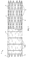
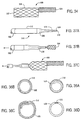
- Prosthesis 10 comprises a perforate tubular frame 12 which includes a plurality of independent (non-connected) band members 14 separated from each other by small gaps 16.
- the tubular frame 12 is covered by an inner liner 18 and an outer liner 20, where the inner and outer liners together encase or sandwich the otherwise free-floating band members 14 therebetween.
- the inner and outer liners are joined together along circumferential lines 22, preferably aligned with the gaps 16 between adjacent band members 14.
- the liners may be joined together by stitching, heat welding, ultrasonic welding, or the like.
- the liners 18 and 20 are formed from polymeric sheet material and are joined together by ultrasonic welding.
- the band members 14 at each end of the graft 10 will have to be further secured to the liners 18 and 20. For example, they could be stitched, welded, or otherwise joined to the liners to hold them in place.
- the graft 10 will typically have a length in the range from about 50 mm to 500 mm, preferably from 80 mm to 200 mm, with a relaxed diameter in the range from about 4 mm to 45 mm, preferably being in the range from 5 mm to 25 mm.
- Such graft structures will be particularly suitable for treating vascular aneurysms.
- the delivery catheters of the present invention facilitate deployment of resilient prostheses by reducing friction at the prosthesis/catheter interface, avoiding any increase in the stiffness of the delivery system where it is not needed.
- compressed prostheses are largely rigid, which reduces any penalty in flexibility imposed by including hard, friction-reducing runners around the prosthesis.
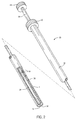
- the sheath 32 has a central lumen 36 extending from a distal end 38 to a proximal handle 40.
- the shaft 34 is slidably received within the central lumen 36 and has a distal end 42 and a proximal handle 44.
- the delivery catheter 30 receives a radially compressible tubular prosthesis P within the annular space between the outer surface of the shaft 34 and the inner surface of the lumen through sheath 32.
- the prosthesis is illustrated as a radially compressed helical coil which expands by unwinding and axial shortening.
- the delivery catheters of the present invention can be used with virtually any radially compressible prosthesis, as described above.
- prosthesis compression may also be provided by a retaining structure which comprises a cover, spaced-apart anchors, or other equivalent structure which maintains the radial compression regardless of the position of the sheath. Using such embodiments, the prosthesis may be uncovered and located prior to release and radial expansion.
- the prosthesis P is anchored by a plurality of penetrating stay members 50 which are circumferentially spaced-apart over the exterior of the shaft 34.
- the stays 50 will be spaced proximally from the distal end 42 of the shaft 34 by a distance which corresponds generally to that of the tubular prosthesis P which is to be maintained on the delivery catheter 30.
- the penetrating stays 50 will extend radially outward by a distance sufficient to engage the interior surface of the lumen 36 of the sheath 32. In that way, the penetrating stays 50 will be able to anchor the proximal end of the tubular prothesis P when it is held within the catheter.
- the prosthesis P will remain anchored as the sheath 32 is drawn proximally over the shaft 34, as illustrated in Figs. 3-5.
- the sheath 32 When initially placed in a body lumen L, the sheath 32 covers substantially the entire length of the prosthesis P with the penetrating stays 50 engaging the proximal portion of the prosthesis P, as illustrated in Fig. 3. The sheath 32 may then be retracted proximally, partially releasing the prosthesis P, as illustrated in Fig. 4. The proximal portion of the prosthesis P, however, remains anchored by the penetrating stays 50 so long as the sheath 32 remains positioned over the stays. Once the sheath 32 is withdrawn to the proximal side of the stays 50, as illustrated in Fig. 5, the prosthesis P will be fully released. Prior to such full release, however, the prosthesis P may be recaptured by advancing the sheath 32 in the distal direction relative to the shaft 32.
- the catheter 30 may optionally be provided with a journal sleeve 60 near its proximal end.
- the journal sleeve 60 is preferably mechanically coupled to the shaft 34 by pins 62 which extend through slots 64 in the sheath 32.
- the journal sleeve 60 can be anchored within an introducer sleeve or other access device (not illustrated) which is used to provide percutaneous access to the body lumen being treated.
- an introducer sleeve or other access device (not illustrated) which is used to provide percutaneous access to the body lumen being treated.
- Journal sleeve 60 permits anchoring of the shaft 34 (which carries the prosthesis P) while allowing the sheath 34 to remain freely translatable relative to both the journal sleeve 60 and the catheter shaft 34.
- the catheter 30 may vary widely, depending on the intended usage.
- the catheter 30 will typically have a length in the range from about 50 cm to 250 cm, preferably from 100 cm to 200 cm, and a diameter in the length from about 3 mm to 8 mm, preferably from 4 mm to 6 mm. These dimensions generally refer to the exterior dimensions of the sheath 32.
- the catheter shaft 34 will have a smaller diameter, typically in the range from 1 mm to 5 mm, preferably from about 1.5 mm to 3 mm, allowing a sufficient annular space therebetween to receive the prosthesis P.
- the catheter shaft will also have a length which is greater than that of the sheath, usually by a distance sufficient to accommodate the length of the prosthesis which is being delivered, typically from 5 cm to 25 cm, preferably from 7.5 cm to 15 cm.
- the catheters will generally be constructed of natural or synthetic polymers, such as silicone rubber, natural rubber, polyvinylchloride, polyurethanes, polyesters, polyethylenes, polytetrafluoro-ethylenes (PTFE), and the like.
- the catheter sheath and shaft may be formed as composites having a reinforcement layer incorporated within a polymeric body in order to enhance strength, flexibility, and toughness. Suitable reinforcement layers include wire mesh layers, braided layers, and the like.
- the tubular members of the present invention may be formed by extrusion, with the tubular diameter modified by heat expansion and/or shrinkage using conventional techniques. Particular techniques for forming vascular and other catheters suitable for use in the present invention are well described in the patent and medical literature.
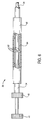
- Catheter 70 comprises the sheath 72, a shaft 74, and a prosthesis-containment sheath 76.
- a prosthesis P is contained between the sheath 72 and the shaft 74, generally as described above in connection with delivery catheter 30.
- the sheath 72 differs from that of sheath 32 in that sheath 72 has an outwardly flared distal end 78, as best seen in Fig. 8.
- the distal end 78 is a resilient structure, typically formed from the material of the sheath 72 itself and optionally having a plurality of elastic reinforcement elements imbedded therein to maintain the desired flared configuration, and may be radially collapsed by the containment sleeve 76, as illustrated in Fig. 7.
- the flared distal end of the sheath 72 is advantageous since it facilitates the release and recapture of the prosthesis P.
- the flared distal end 78 of catheter 70 will usually have a fully expanded diameter d at the distal tip 79 in the range from 10 mm to 30 mm, preferably from 15 mm to 25 mm.
- the distal tip of diameter d will usually be greater than the diameter of the proximal portions of the sheath 72 by a factor from 2 to 8, preferably being from 2.5 to 5.
- the flare will extend over an axial length l in the range from 3 mm to 30 mm, preferably from 5 mm to 20 mm.
- Catheter 80 comprises the sheath 82 having an annular lumen 84 extending from its proximal end 86 to its distal end 88.
- the annular lumen 84 is connected to an inflation port 90 on a proximal housing 92.
- a shaft 94 extends through the central lumen of the sheath 82 and carries a prosthesis P near it distal end.
- the distal end of the sheath 82 is formed so that, upon inflation with a non-compressible fluid medium, typically saline or other biocompatible liquid, it assumes the outwardly flared configuration shown in Fig. 10.
- a non-compressible fluid medium typically saline or other biocompatible liquid
- the structure is sufficiently elastic, however, so that removal of the inflation medium will permit the sheath 82 to resume its non-flared configuration, as illustrated in Fig. 9. Flaring of the distal end of sheath 82 facilitates both release and recapture of the prosthesis P, as with the embodiment of Figs. 7 and 8.
- distal end 88 of sheath structure 82 comprises an outer layer 91 secured to an inner layer 92 at their respective distal ends.
- Both layers 91 and 92 will be composed of a flexible, non-distendable material, such as polyethylene terephthalate (PET), or other reinforced material, such as an elastomeric or non-elastomeric material reinforced with a non-distendable mesh.
- PET polyethylene terephthalate
- the outer layer will be shorter than the inner layer so that when the annular lumen 84 is inflated, the distal end will flare as shown in Fig. 10.
- FIGs. 11 and 12 Alternative mechanisms for providing a deployable flare at the distal end of a prosthesis-containment sheath are illustrated in Figs. 11 and 12.
- the sheath 100 in Fig. 11 has a distal end 102 including a plurality of axially aligned, circumferentially spaced-apart heat memory alloy members 104.
- the heat memory alloys are selected to have a temperature transition where they assume a straight, non-flared configuration at low temperatures, as illustrated in full line in Fig. 11. At body temperature, however, the members 104 assume an outwardly flared configuration, as illustrated in broken line.
- Suitable alloy materials include nickel-titanium alloys which may be heat treated to provide the proper shapes and transition temperature.
- Sheath 110 illustrated in Fig. 12 has a resilient, flared structure formed at its distal end 112.
- the flared distal end 112 is contained in an end cap 114 which may be distally advanced (as illustrated in broken line) by shaft 116 to release the flared end structure, as shown in broken line.
- FIG. 13-15 An alternative structure for facilitating the release and recapture of a prosthesis from a delivery catheter according to the present invention is illustrated in Figs. 13-15.
- a catheter 118 is provided with a sheath 120, shaft 122, and penetrating stays 124, generally as described above in connection with Figs. 2-5.
- the catheter 118 further includes an eversible membrane 126 which is attached at a first end 128 to the shaft 122, and at a second end 130 to the inner surface of the lumen of sheath 120.
- the membrane 126 will be formed from a flexible, preferably lubricous and non-compliant material, such as PET, nylon, polytetrafluoroethylene (PTFE), any of which may be wire- or braid-reinforced, or the like.
- the prosthesis P will remain anchored on the shaft 122 by penetrating stays 124 as the sheath 120 is partially withdrawn (Fig. 14).
- the membrane 126 folds back over itself (everts) as the sheath 120 is retracted so that there are always two layers of the membrane between the distal end of the sheath and the prosthesis P.
- the double-layer structure of the membrane provides a high degree of lubricity during the release and optional recapture of the prosthesis P. Complete release of the prosthesis P is illustrated in Fig. 15.
- the delivery catheter 150 includes a shaft 152 having a pair of axially spaced-apart stays 154 and 156.
- a pull wire 158 extends through a lumen 160 of shaft 152 and through protrusions on each of the stays 154 and 156.
- a guide wire GW is received through the shaft 152 in order to permit vascular introduction by conventional techniques.
- the radially compressible prosthesis P (such as graft 10) is placed over the distal end of the shaft extension 162, generally being aligned between the stays 154 and 156.
- the pull wire 158 is then advanced through the stays 154 and 156 so that it passes through each end of the prosthesis P to maintain the prosthesis P in place until the pull wire is withdrawn. While the pull wire 158 remains in place, a prosthesis-containment sheath 164 may be axially advanced over the graft to radially compress the graft into its desired low profile diameter.
- the sheath 164 includes a flared (i.e., outwardly tapered) distal end 166 to facilitate advancing the sheath over the prosthesis P, in particular so that the prosthesis P may be recaptured when it is partially deployed.
- the outward flare may be permanently fixed in the body of the sheath, but will preferably be selectively deployable between the flared and non-flared configuration, using any of the mechanisms described above.
- a prosthesis cartridge 200 comprises a sheath extension 202 having a distal end 204 and a proximal end 206.
- a prosthesis P is contained within the sheath extension 202 and is mounted over a shaft extension 208.
- the prosthesis P will be anchored on the shaft extension 208 using penetrating stays (not shown) as described in connection with previous embodiments.
- the prosthesis cartridge 200 is releasably connectable to a delivery catheter 221 including a sheath 220 (or other elongate member) and shaft 222.
- the proximal end of the cartridge sheath 202 is configured to couple to the distal end of the catheter sheath 220.
- the proximal end of the shaft extension 208 is configured to selectively couple to the distal end of the shaft 222.
- the prosthesis which is part of cartridge 200 (and preferably packaged in a separate, sterile pouch or other container) may then be attached to the distal end of the delivery catheter (which is separately packaged in a sterile pouch or other container) having the necessary sheath and shaft connections.
- the catheter sheath 220 could alternatively comprise other, non-tubular structures (elongate members). It is necessary only that the elongate member be able to connect to the sheath extension 202 to be proximally retracted over the prothesis P (and optionally distally advanced) to effect release and recapture of the prosthesis as described above.
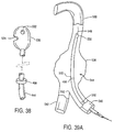
- Delivery catheter 250 includes flexible shaft 252 having a central lumen for receiving a guide wire GW.
- a sheath 254 is slidably mounted over the shaft 252, generally as described for previous embodiments.
- the catheter 250 differs from previous embodiments, however, in the nature of the retaining structure which is used for holding prosthesis P in place on the flexible shaft 252.
- the retaining structure comprises a distal anchor 256, which is conveniently in the form of a cap or other receptacle which can receive a distal end of the prosthesis therein.
- a proximal anchor 258 is mounted at the distal end of a sliding tube 260.
- the prosthesis P will be maintained in its collapsed configuration by the anchors 256 and 258, and sheath 254 will cover the prothesis and anchor structures.
- the sheath 254 may be withdrawn proximally to expose the prosthesis P.
- the prosthesis P remains radially compressed by the anchors 256 and 258, even after the sheath 254 has been fully withdrawn, as illustrated in Fig. 19C.
- the prosthesis P may be fully released by moving the anchors 256 and 218 axially apart in order to free the compressed ends of the prosthesis, as illustrated in Fig. 19D.
- the exposed prostheses Prior to release, however, the exposed prostheses can be carefully positioned without interference from the sheath 254. It is a particular advantage that such partial release is achieved while still being able to readily recapture the prosthesis by readvancing the sheath 254.
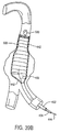
- the retaining structure 280 will fully cover and compress the prostheses P, and will usually be maintained within an outer sheath (not shown) equivalent to the delivery catheter sheaths illustrated previously.
- the retaining structure 280 will maintain radial compression of the prosthesis P within the sheath, regardless of whether the sheath covers the prosthesis.
- the sheath of the associated delivery catheter may be proximally retracted prior to release of the prostheses P.
- the retaining structure 280 comprises a helically wound ribbon, which may optionally be formed as a helically scored or perforated cylinder.
- the retaining structure 280 is mounted on flexible shaft 284, typically with a distal portion of the helical ribbon attached directly or indirectly to the shaft.
- a pull cord 286 is attached to a proximal end of the helical ribbon, and the ribbon may be withdrawn from over the prostheses P by pulling proximally on the pull cord, as illustrated in Fig. 20b.
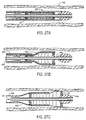
- Retaining structure 300 comprises a cylinder 302 having a helical wire 304 disposed over its surface.
- the wire 304 when pulled from the cylinder 302, separates adjacent sections of the cylinder so that they break apart, as illustrated in Fig. 21B.
- a first pull cord 306 to a proximal end of the wire 304, the wire can be withdrawn by pulling proximally.
- the resulting ribbon-like section of the cylinder may then be withdrawn by pulling on a second pull cord 308, also as shown in Fig. 21B.
- the prostheses P is thus released from the catheter.
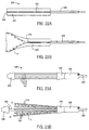
- FIGs. 22A and 22B structure 320 is a cylinder 322 having a single axial break line 324 formed along one side thereof. It will be appreciated that more than one axial break line may be provided, Only one is illustrated, however, for convenience.
- a slide structure 326 secured to the cylinder 322 at a distal end of the break line 324.
- a pull cord 328 is attached to the slide structure 326. Optionally, multiple pull cords could be used.
- the slide structure 326 may be drawn proximally in order to open the breakline 324 in the manner of a zipper, as illustrated in Fig. 22B. In this way, the prostheses P can be released.
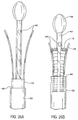
- the retaining structure 340 comprises a plurality of individual resilient axial members 342 which are captured at their distal ends and an anchor 344.
- the axial elements 342 are permanently mounted in a ring structure 346 at the distal end of catheter body 348.
- the anchor 344 is secured at the distal end of a flexible shaft 350.
- the axial elements 342 are spring-loaded so that when the anchor 344 is moved distally by advancing the shaft 350, as illustrated in Fig. 23b, the individual elements will spring radially apart at the distal end. In this way, prosthesis P can be released from the retaining structure 340.
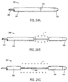
- the retaining structure 360 is a thin-walled tube 362 which is weakened along a circumferential (or helical) line 364, typically in the form of a score, perforation, or the like.
- Flexible shaft 366 secured to a distal end cap 368. By axially advancing the shaft 366, the end cap 368 and the attached portion of cylinder 362 between the score line 364 and the end cap will be pulled away from the remainder of the cylinder 362. In this way, the prostheses P can be released.
- the prostheses is first partially released, as shown in Fig. 24B. After the cylinder segments are fully spaced-apart, the prostheses is fully released, as shown in Fig. 24C.
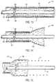
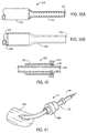
- a delivery catheter 430 constructed in accordance with the principles of the present invention comprises a tubular cover 432 and a shaft or inner catheter body 434.
- Cover 432 has a central lumen 36 extending from a proximal end 438 to a distal end 440.
- Shaft 434 is slidably received within central lumen 436 and extends proximally of the proximal end of cover 432.
- a plurality of runners 442 extend distally from the distal end of shaft 434. Runners 442 line a portion of the inner surface of lumen 436, and slide within the lumen with the shaft.
- Shaft 434 also has a lumen, in which a core shaft 444 is slidably disposed. Core shaft 444 has a guidewire lumen 446. Guidewire lumen 446 optionally receives an intravascular ultrasound (IVUS) imaging transducer to provide imaging prior to, during, and after deployment of the prosthesis.
- Nosecone 448 is fixed to the distal end of core shaft 444, and can therefore move independently of runners 442.
- Graft 10 is radially compressed and restrained within the plurality of runners 442.
- cover 432 prevents runners 442 from expanding outward.
- Runners 442 are formed from a hard material, and distribute the expansion load of prosthesis 10 over the inner surface of central lumen 436.
- the prosthesis does not invaginate in the lumen surface, and is thus able to slide relative to the cover in response to a moderate distal force.
- the deploying force is applied proximally against a slider 450 attached to distal end 438 of cover 430, while holding a lure fitting 452 at the distal end of shaft 434.
- An additional lure adaptor 454 at the distal end of core shaft 444 allows the core shaft to be releasably secured to the shaft 434.
- graft 10 is inserted between the outward flexed runners and compressed by withdrawing runners 442 and shaft 434 into the distal end 440 of cover 432.
- Nosecone 448 and core shaft 444 are shown attached to shaft 434 during loading.
- nosecone 448 may be attached to core shaft 444 after the loading of prosthesis 10.
- Prosthesis 10 is preferably formed of a heat memory alloy such as NitinolTM. To maintain graft 10 in a compressed state, the loading process may be done in a cold environment, such as that provided by a cold spray, liquid nitrogen, freon, an air vortex, or the like.
- graft 10 within a body lumen 460 begins by positioning catheter 430 at a target location. As illustrated in Fig. 27B, graft 10 is allowed to expand by retracting cover 432, proximally relative to shaft 434 and core shaft 444. As cover 432 is retracted, runners 442 maintain their axial position, sliding over the inner surface of cover 432. Once the graft 10 has fully expanded within body lumen 60, it is axially anchored by expansion against the lumen wall between the runners. Runners 442 may then be retracted proximally with shaft 434 and nosecone 448.
- runner 442 allows shaft 434 to be retracted smoothly, with little possibility of dragging graft 10 from the target position.
- the graft cover may also help to reduce friction during deployment.
- the possibility of dragging the prosthesis is further reduced by retracting nosecone 448 having a tapered proximal end 464 independently from shaft 434, as illustrated in Fig. 28.
- the runners may also be used to help recapture a partially-deployed prosthesis.
- Cover 432 must be strong enough to withstand the expansion force of graft 10 but must also be flexible to allow intravascular atraumatic maneuvering.
- Cover 432 is optionally formed of a high strength thermoplastic elastomer such as HytrelTM.
- cover 432 may be formed of a braided reinforced polymer tubing or a linear reinforced tubing, preferably having fibers of a polyamide such as KevlarTM, SpectraTM, or the like, embedded to improve tensile strength without reducing flexibility.
- the cover includes a radiopaque contrast medium, e.g., a B 4 SO 4 compound, to allow imaging of the placement of catheter 30 within a body lumen using fluoroscopy.
- Shaft 434 is preferably formed from PEEK, nylon, or the like, to provide column strength.
- Runners 442 are formed from a high strength biocompatible alloy such as NitinolTM, stainless steel, or a stainless steel alloy. Runners 442 are bonded to shaft 434, preferably being laminated between inner and outer layers of nylon, a thermoplastic elastomer such as PebaxTM, or the like.
- Core shaft 444 is also preferably formed of PEEK.
- Nosecone 448 may be formed of stainless steel and bonded to the distal end of core shaft 444, or may alternatively be molded of a radiopaque plastic comprising PebaxTM, nylon, HytrelTM, or the like.
- nosecone 448 preferably includes a radiopaque element, thereby giving an indication of the location of the distal end of graft 10 during fluoroscopically guided prostheses placement.
- core shaft 444 further supports marker ring 466, comprising platinum, barium, or the like, to provide a sharp radiographic contrast.
- distal force imparting structure 467 is bonded to the core shaft to slide the compressed prosthesis distally over the runners.
- a helical shaft 435 provides high column strength with flexibility.
- Helical shaft 435 is formed from a tightly wound, high strength metal, preferably comprising stainless steel.
- Helical shaft 435 is easily welded to runners 442, where similar metals are used for both.
- runners 442 are laminated to helical shaft 435 with inner and/or outer layers of nylon, PebaxTM, or the like.
- a composite cover 433 comprising polymer reinforced tubing having braided or linear KevlarTM, SpectraTM, or the like, further enhances flexibility of the delivery catheter of the present invention.
- the delivery catheters of the present invention significantly reduce the force required to deploy a prosthesis within a body lumen. Nonetheless, the force required to withdraw cover 432 remains substantial.
- the present invention further provides a housing 470 to be attached to the distal end of shaft 434, as illustrated in Fig. 30. Rotation of handle 472 moves follower 474 along a linear screw. Slider 450 at the proximal end of cover 432 is driven axially by the movement of the follower. Cover 432 is withdrawn during deployment of the prosthesis by articulating handle 472 so as to drive slider 450 toward lure fitting 452 at the proximal end of shaft 434.
- the force required to withdraw the cover is typically on the order of 1 to 10 lbs., requiring only a modest mechanical advantage.
- a mechanical advantage ratio in the range from 5 to 50, as measured from the linear travel at the outside edge of handle 472 to the linear motion of follower 474 provides a highly controlled deployment
- a wide variety of mechanical linkages are available to provide such a mechanical advantage. It is particularly advantageous to provide a mechanism which allows manipulation with a single hand, as this leaves the alternate hand free to manipulate the cover relative to an introducer sheath.
- housing 470 allows independent manipulation of core shaft 444 using second lure fitting 454, as described above regarding Fig. 28.
- an alternative cover 480 provides an atraumatic distal end 482 with a reduced nosecone diameter, or, alternatively, no nosecone at the distal end of core shaft 444.
- Atraumatic cover 480 includes a series of splits 484 to allow the distal tip of atraumatic cover 480 to open during deployment of prosthesis 10.
- a further alternative cover 490 having runners 492 embedded within the central lumen, will also reduce the friction between the prosthesis and the cover during prosthesis placement. Furthermore, such a structure eliminates any danger of injury to the walls of a body lumen during placement by a distal movement of the exposed runners. Moreover, similar safety advantages could be obtained using the delivery catheter of Fig. 25 by retaining runners 442 within cover 432 during deployment of prosthesis 10.
- An alternative structure must be provided to apply a distal force against the prosthesis, such as distal force imparting structure 467 shown in Fig. 29A.
- FIGs. 33A and 33B alternative cross sections 494 and 496 for a delivery catheter tubular cover or shaft will provide additional column strength without a corresponding increase in stiffness.
- Slots 495 are also suitable for receiving the runners, thus forming the runner/shaft laminated bond.
- Indents 497 may receive the free distal portion of the runners to prevent rotation of the prosthesis relative to the cover during manipulation of the shaft.
- a smooth cover lumen facilitates such rotation by allowing the runners to slidingly rotate against the cover lumen surface.
- Branched prostheses are particularly useful for treatment of aortic aneurysms which extend distally into one or both of the iliac arteries.
- Branched prosthesis 499 has a large diameter end 502 and a small diameter end 504. Large diameter end 502 features a large common lumen which is in open communication with a first branched lumen of small diameter end 504. The common lumen is further opened at branch 506.
- Branched prosthesis 499 is formed of a perforate tubular member similar to that used in graft 10. Branched prosthesis 499 may further include a liner as described above.
- aortic aneurysms using branched prostheses requires placement of the large diameter end in the abdominal aorta with the small diameter end extending into one of the iliac arteries. It will further be understood that it is critical to have branch 506 correctly oriented toward the alternate iliac artery for proper blood flow, whether or not a second tubular prosthesis is placed within open branch 506 and extending into the alternate iliac artery.
- an exemplary expandable cover 510 for use with branched prostheses comprises a tube 512 and a radially expandable cylindrical structure 514 extending distally of body 512.
- Body 512 is formed of material similar to that used for cover 432 of the delivery catheter of Fig. 25.
- Expandable structure 514 comprises a braided, expandable mesh tubing which is bonded or molded into body 512. The mesh tubing expands easily, and is unable to radially compress branched prosthesis 499, but provides a relatively hard surface against which the branched prosthesis can slide distally during deployment.
- An elastomeric outer coating 518 is disposed over the entire length of the expandable structure and extends proximally onto body 512.
- Elastomeric outer coating 518 comprises rubber, latex, silicone, polyurethane, a thermoplastic urethane such as C-FLEXTM, or the like, and provides the radial compression which retains branched prosthesis 499 in a radially compressed mode.
- alternative radially expandable cylindrical structures may be formed by extending the material of body 512, and cutting a series of slits to form extended arms 522.
- a single slit may be used, and the material may be overlapped to form a coil 524.
- a pliable material may be folded over and extended from body 512 to form a folded tube 526.
- Folded tube 526 is preferably formed of a low friction, pliable material such as PTFE or the like.
- open tube 528 having a biasing means 530 such as a metal spring or an elastomeric material, may also be used.
- expandable cover 510 The use of expandable cover 510 will be described with reference to Figs. 37A-37C.
- Branched prosthesis 499 is loaded into expandable cover 510 with a small diameter end 504 of the prosthesis in a distal expandable structure 514.
- Large diameter end 502 of branched prosthesis 499 is radially restrained within body 512.
- the outer diameter of expandable structure 514 is less than the outer diameter of body 512, advantageously allowing the distal end of the delivery catheter to extend into the narrower iliac arteries during a superior placement.
- Expandable structure 514 expands to pass the large diameter end 502 as branch 506 slides distally. Large diameter end 502 and body 512 which restrains it need never enter the restricted diameter of the iliac artery. Similarly, the present expandable cover will be useful for placement of any prosthesis having a distal taper, a smaller distal segment, or a small end and a large portion along its axis.
- An orientation indicating nosecone 530 comprises a stainless steel or other radiopaque structure having a hole 532 and a notch 534.
- orientation indicating nosecone 530 will provide an indication of the orientation of a branch prior to deployment of a branched prosthesis or stent.
- marker ring 466 is a predetermined distance proximal of a branch 505 when a branched graft 500 is radially restrained within the delivery catheter (see Fig. 39A), thus providing a branch axial marker.
- a wide variety of asymmetric radiopaque shapes and markers may be used with the present delivery catheter system. It is preferable that the markers remain in position during withdrawal of the cover, and that the markers clearly identify the orientation of a branch 505. It is particularly prefered that marker ring 466 be toward the branch end from branch 505 to ensure the branch is not placed within the iliac artery.
- a method of placement of a branched prosthesis within an aortic aneurysm using the present delivery catheter having the orientation indicating nosecone 530 will be described in regard to branched graft 500.
- An aneurysm 536 located on an abdominal aorta 538 in close proximity to first and second iliacs 540, 542 is to be treated with a branched graft.
- a delivery catheter 544 having orientation indicating nosecone 530 is positioned from an inferior placement using a guidewire 548.
- the axial position and length of branched graft 500 is indicated by orientation indicating nosecone 530 and by a proximal indicator 550, which is structural similar to marker ring 466, and is affixed to the core shaft adjacent to the proximal end of the prosthesis.
- Marker ring 466 is used as a branch axial indicator, and is placed distally of the body lumen branch 552 to ensure that the branch of branching graft 500 remains within the common lumen.
- the rotational orientation of the graft is indicated by notch 534 on orientation indicating nosecone 530. The precise rotational orientation may be determined by lining up hole 532 with the imaging energy stream.
- the cover 432 may be withdrawn proximally as illustrated in Fig. 39B. Shaft 434 and core shaft 444 remain at the target position, allowing runners 442 to slide over the central lumen 436 of cover 432. Additionally, orientation indicating nosecone 530 and marker ring 466 remain at the axial location of branched graft 500. Alternatively, the cover 432 may be withdrawn a little at a time, with the runners withdrawn back simultaneously into the cover each time. In a still further alternative, runners 442 may remain within cover 432, and branched graft 500 may be held at the target position by a force imparting structure attached to core shaft 444. Such force imparting structures are more fully explained in application Serial No. 08/294,021, previously incorporated herein by reference. Optionally, core shaft 444 remains stationary while withdrawing the runners so that nosecone 530 does not drag branched prosthesis 500 from the target location.
- runners 442 and nosecone 530 are withdrawn simultaneously through the branched prosthesis.
- Core shaft 444 and shaft 434 which are optionally attached, are withdrawn proximally.
- the runners may be withdrawn into cover 432, or the delivery catheter may move proximally with the runners remaining exposed.
- core shaft 444 is withdrawn independently of shaft 434 in a proximal direction.
- Very little force should be required to withdraw nosecone 530 independently of runners 442. Any friction which is encountered indicates that nosecone 530 may be snagged, for example, on branch 505.
- the surgeon may then manipulate core shaft 444 free nosecone 530, and thereby overcome such a snag.
- orientation indicating nosecone 530 is fully withdrawn shaft 434 and runners 442 may be retracted, leaving branched graft 500 in place.
- a secondary tubular prosthesis may be placed extending from branch 505 of branched prosthesis 500 down to second iliac 542.
- Delivery catheter 430 has a standard nosecone 448, as the rotational orientation is not critical.
- the distal and proximal ends of the prosthesis may be indicated by the nosecone 448 and proximal marker 550.
- marker ring 466 be located a predetermined distance proximal of the distal end of the prosthesis.
- Delivery catheter 30 is then axially positioned with marker ring 466 proximal of branch 505 to avoid the distal end of the prosthesis extending too far into branched graft 500 and folding over in the flow. Marker ring 466 thus acts as a safety marker.
- the apparatus and methods of the present invention provide a cover which is smoothly retractable relative to a radially compressed prosthesis.
- a substantial amount of friction may be encountered at the introduction sheath where the present catheters enter a patient's body.
- Introduction sheaths must provide hemostasis for catheters and other invasive surgery apparatus of various sizes and configurations.
- Such introduction sheaths typically include a resilient sealing valve which radially compresses the outermost layer of the catheter.
- Such introduction sheath valves impose a substantial amount of friction against the catheter, making smooth withdrawal of a delivery catheter cover problematic. Therefore, the present invention further provides a friction reducer tube, as illustrated in Fig. 40.
- Friction reducer tube 570 comprises a distally tapered tube 572, a proximal o-ring housing 574, and an o-ring 576.
- Tapered tube 572 is slightly larger in diameter than cover 430 of the present delivery catheter.
- O-ring 576 provides hemostasis against the cover, but slides axially with little friction.
- an introduction sheath 580 is inserted into the patient body 582.
- Delivery catheter 430 is slidably disposed within friction reducer tube 570, and is introduced into the patient body through introduction sheath 580.
- Friction reducer tube 570 may then be slid distally so that the hemostasis valve rides over tapered tube 572.
- one surgeon retracts cover 430, while another surgeon manipulates the distal end of cover 432 relative to shaft 434, ideally using a mechanical advantage mechanism as illustrated in Fig. 30.
- a brace 590 optionally restrains the prosthesis at the target location while withdrawing cover 432.
- Brace 590 attaches to introducer sheath 580 with a locking collar 592.
- Bar 594 extends proximally from locking collar 592, and is slidably received by tabs 596 protruding from housing 470.
- a set screw 598 is tightened to fix the distance between the proximal end of delivery catheter 430 and the introduction sheath 580.
- Rotating handle 472 thus withdraws cover 430 proximally through introduction sheath 580 without distally advancing shaft 434. This minimizes the danger of advancing the exposed runners into the lumen wall during deployment, and thus allows deployment by a single surgeon.
- the compressive load on bar 594 is reduced by friction reducer tube 570.
- a wide variety of compression bearing structures could be used in place of bar 590.
- a telescoping tube with single or multiple overlapping sections having set screws would eliminate the protruding proximal end of the rod.
- Such a telescoping tube may optionally surround catheter 430 between the introducer sheath and housing.
- a flexible tube having good column stiffness disposed over the delivery catheter also prevents axial movement of the prosthesis, and avoids the long, rigid, and potentially cumbersome bar structure.
- Such a flexible tube preferably comprises a tightly wound coil analogous to flexible shaft 435 shown in Fig. 29B.
- telescoping flexible overlapped tubes usually having a locking device such as set screws, compressive clamps, or the like, are preferred.
- the brace of the present invention may advantageously be used with alternative proximal housings having a wide variety of mechanisms for translating the cover relative to the shaft, including electric motors, foot operated linkages, and the like.
- the invention concerns a delivery catheter for positioning radially compressible prostheses, said catheter comprising:
- the sheath may have a fixed or deployable outwardly flared distal end to facilitate proximal and distal motion over the prosthesis, in which case means may be provided on the sheath for reconfiguring the distal end of the sheath between a non-flared configuration and a flared configuration, wherein the reconfiguring means may comprise an inflatable bladder and means for inflating said bladder, wherein the bladder flares the distal tip of the sheath outward when inflected.
- the distal end of the catheter may comprise a resilient structure having a fixed flared configuration.
- the delivery catheter may comprise an axially translatable cap structure which in a proximal position captures the distal end to hold it in a non-flared configuration.
- the delivery catheter may comprise a containment sleeve slidably disposed over the sheath, wherein the sleeve closes the flared end when distally advanced and allows the flared end to open when proximally retracted.
- the flared distal end of the sheath may comprise a structure including heat memory alloy components which define the flared structure of the distal end of the sheath at body temperatures and which assume a non-flared configuration at below body temperature.
- the delivery catheter may comprise a tubular membrane attached at one end of the shaft at a location proximal of the retaining structure and at the other end to the inside of the sheath, wherein the membrane envelops the prosthesis when said prosthesis is radially compressed within the sheath and wherein the membrane everts as the sheath is retracted proximally relative to the shaft.
- the retaining structure of the delivery catheter may comprise at least one locking stay on the shaft, in which case the locking stay may be disposed over the outside of the shaft and extends radially outward by a distance sufficient to engage the interior surface of the sheath, whereby the stay will extend through an aperture in the prosthesis to hold the prosthesis axially in place relative to the shaft as the sheath is axially translated relative to the shaft.
- the retaining structure may comprise at least two circumferentially spaced-apart locking stays disposed over the shaft.
- the retaining structure may comprise a cover which is detachably secured over the radially compressible prosthesis and means operable from the proximal end of the flexible shaft for detaching the cover from over the prosthesis to release said prosthesis, in which case the cover may be a cylinder and the detaching means is a mechanism selected from the group consisting of (a) a cord for splitting the cylinder along at least one axial or spiral line by drawing proximally on the cord, (b) an axially translatable end cap which captures a plurality of resilient, radially outwardly flared axial elements of the cylinder, and (c) means for axially separating two halves of the cylindrical cover.
- the delivery catheter may comprise a journal sleeve slidably disposed over the sheath, wherein the journal sleeve permits external anchoring of the catheter while the sheath can still be translated relative to the shaft.
- the delivery catheter may comprise a lock which selectively fixes the shaft relative to the journal sleeve while permitting the sheath to be axially translated relative to the shaft and journal sleeve.
- the delivery catheter may be provided with a shaft having a coupling mechanism spaced inward for the distal end and the sheath has a coupling mechanism spaced inward from the distal end, whereby different distal ends of the catheter may be attached.
- the invention further concerns a catheter system comprising a radially compressible prosthesis held by the retaining structure of the shaft of the delivery catheter as defined before.
- the prosthesis may be axially anchored by the retaining structure and may be radially compressed by the sheath itself. It is further possible that the prostheses may be axially anchored and radially compressed by the retaining structure.
- the invention concerns a delivery catheter for use with a prosthesis cartridge including a shaft extension, a sheath extension slidably received over the shaft extension, and a prosthesis radially compressed over the shaft extension and within the sheath extension, said delivery catheter comprising:
- the invention further concerns a set of prosthesis cartridges comprising a plurality of prosthesis cartridges as defined in the last paragraph, wherein at least some of said cartridges comprise prostheses having different lengths, and/or wherein the cartridge is contained in a sterile package.
- a method for preparing a prosthesis delivery catheter comprises:
- the invention concerns a delivery catheter for placement of a radially compressible prosthesis, the catheter comprising:
- the delivery catheter may further comprise a plurality of axially disposed elongate runners affixed together at their proximal ends;
- the invention concerns a delivery catheter for placement of a compressible prosthesis, the catheter comprising:
- the delivery catheter may have a shaft structure which comprises a core shaft slidably disposed within the runners, the core shaft having a guidewire lumen and means for releasably attaching the core shaft to the runners at the proximal end of the shaft structure, wherein the core shaft and distal end of the cover are capable of presenting an atraumatic distal catheter end;
- the invention concerns a delivery catheter for placement of a resilient, radially compressible prosthesis within a patient body, the catheter passing through an introduction sheath having a valve seal, the catheter comprising:
- the invention concerns also an improved delivery catheter for placement of a branching, radially compressible prosthesis in a branching body lumen, the catheter of the type having an elongate shaft structure including a proximal end, a distal end, an axis therebetween, and a prosthesis receptacle near the distal end, the improvement comprising:
- the delivery catheter may further comprise a branch axial marker on the shaft structure within the prosthesis receptacle, and/or
- the invention concerns also an improved prosthesis delivery catheter for placement of a secondary radially compressible prosthesis within a branch of a branching prosthesis, the branching prosthesis placed in a branching body lumen, the catheter of the type having an elongate shaft structure including a proximal end, a distal end, and a prosthesis receptacle near the distal end, the improvement comprising:
Applications Claiming Priority (5)
| Application Number | Priority Date | Filing Date | Title |
|---|---|---|---|
| US29002194A | 1994-08-12 | 1994-08-12 | |
| US290021 | 1994-08-12 | ||
| US08/475,200 US5683451A (en) | 1994-06-08 | 1995-06-07 | Apparatus and methods for deployment release of intraluminal prostheses |
| US475200 | 1995-06-07 | ||
| EP95112564A EP0696447B1 (fr) | 1994-08-12 | 1995-08-10 | Dispositif pour la mise an place d'une prothèse intraluminale |
Related Parent Applications (1)
| Application Number | Title | Priority Date | Filing Date |
|---|---|---|---|
| EP95112564A Division EP0696447B1 (fr) | 1994-08-12 | 1995-08-10 | Dispositif pour la mise an place d'une prothèse intraluminale |
Publications (1)
| Publication Number | Publication Date |
|---|---|
| EP0948946A1 true EP0948946A1 (fr) | 1999-10-13 |
Family
ID=26965970
Family Applications (3)
| Application Number | Title | Priority Date | Filing Date |
|---|---|---|---|
| EP99113203A Withdrawn EP0948946A1 (fr) | 1994-08-12 | 1995-08-10 | Dispositif pour la mise en place d'une prothèse intraluminable |
| EP99113204A Expired - Lifetime EP0943302B1 (fr) | 1994-08-12 | 1995-08-10 | Cathéter pour la mise en place d'une prothèse endoluminale |
| EP95112564A Expired - Lifetime EP0696447B1 (fr) | 1994-08-12 | 1995-08-10 | Dispositif pour la mise an place d'une prothèse intraluminale |
Family Applications After (2)
| Application Number | Title | Priority Date | Filing Date |
|---|---|---|---|
| EP99113204A Expired - Lifetime EP0943302B1 (fr) | 1994-08-12 | 1995-08-10 | Cathéter pour la mise en place d'une prothèse endoluminale |
| EP95112564A Expired - Lifetime EP0696447B1 (fr) | 1994-08-12 | 1995-08-10 | Dispositif pour la mise an place d'une prothèse intraluminale |
Country Status (4)
| Country | Link |
|---|---|
| US (3) | US5683451A (fr) |
| EP (3) | EP0948946A1 (fr) |
| JP (2) | JP3679466B2 (fr) |
| DE (2) | DE69514589T2 (fr) |
Cited By (10)
| Publication number | Priority date | Publication date | Assignee | Title |
|---|---|---|---|---|
| WO2007059293A1 (fr) * | 2005-11-17 | 2007-05-24 | The Cleveland Clinic Foundation | Appareil et méthode pour délivrer des prothèses intraluminales alignées |
| US7758624B2 (en) | 2000-11-13 | 2010-07-20 | C. R. Bard, Inc. | Implant delivery device |
| US8020275B2 (en) | 2005-11-17 | 2011-09-20 | The Cleveland Clinic Foundation | Method for compressing intraluminal prostheses |
| US8414635B2 (en) | 1999-02-01 | 2013-04-09 | Idev Technologies, Inc. | Plain woven stents |
| US8419788B2 (en) | 2006-10-22 | 2013-04-16 | Idev Technologies, Inc. | Secured strand end devices |
| US8876881B2 (en) | 2006-10-22 | 2014-11-04 | Idev Technologies, Inc. | Devices for stent advancement |
| US9023095B2 (en) | 2010-05-27 | 2015-05-05 | Idev Technologies, Inc. | Stent delivery system with pusher assembly |
| CN106580529A (zh) * | 2016-12-26 | 2017-04-26 | 微创心脉医疗科技(上海)有限公司 | 术中支架的安装方法与释放方法以及输送装置 |
| WO2018054275A1 (fr) * | 2016-09-23 | 2018-03-29 | 杭州启明医疗器械有限公司 | Gaine de cathéter extensible et dispositif d'administration d'un instrument d'intervention |
| WO2022094456A1 (fr) * | 2020-11-02 | 2022-05-05 | Edwards Lifesciences Corporation | Appareil de distribution pour implants prothétiques |
Families Citing this family (775)
| Publication number | Priority date | Publication date | Assignee | Title |
|---|---|---|---|---|
| US5843167A (en) * | 1993-04-22 | 1998-12-01 | C. R. Bard, Inc. | Method and apparatus for recapture of hooked endoprosthesis |
| EP0676937B1 (fr) | 1993-09-30 | 2004-03-17 | Endogad Research PTY Limited | Greffe endoluminale |
| US6689158B1 (en) | 1993-09-30 | 2004-02-10 | Endogad Research Pty Limited | Intraluminal graft |
| DE69419877T2 (de) * | 1993-11-04 | 1999-12-16 | Bard Inc C R | Ortsfeste Gefässprothese |
| US6039749A (en) | 1994-02-10 | 2000-03-21 | Endovascular Systems, Inc. | Method and apparatus for deploying non-circular stents and graftstent complexes |
| DE69533993T2 (de) | 1994-06-08 | 2006-04-27 | CardioVascular Concepts, Inc., Portola Valley | Endoluminales Transplantat |
| US6331188B1 (en) | 1994-08-31 | 2001-12-18 | Gore Enterprise Holdings, Inc. | Exterior supported self-expanding stent-graft |
| US6015429A (en) | 1994-09-08 | 2000-01-18 | Gore Enterprise Holdings, Inc. | Procedures for introducing stents and stent-grafts |
| US6099558A (en) * | 1995-10-10 | 2000-08-08 | Edwards Lifesciences Corp. | Intraluminal grafting of a bifuricated artery |
| US5868753A (en) * | 1995-11-13 | 1999-02-09 | Schatz; Richard A. | Stent retrieval catheter |
| US6106531A (en) * | 1995-12-07 | 2000-08-22 | Schatz; Richard A. | Retrieval shuttle |
| EP0950385A3 (fr) | 1995-12-14 | 1999-10-27 | Prograft Medical, Inc. | Appareil et procédé de déploiement d'un stent à greffer |
| US6042605A (en) | 1995-12-14 | 2000-03-28 | Gore Enterprose Holdings, Inc. | Kink resistant stent-graft |
| WO1997025002A1 (fr) | 1996-01-05 | 1997-07-17 | Medtronic, Inc. | Protheses endoluminales expansibles |
| JP3645911B2 (ja) * | 1996-03-29 | 2005-05-11 | ヴィリー リュッシュ アー・ゲー | ステント |
| FR2748199B1 (fr) * | 1996-05-02 | 1998-10-09 | Braun Celsa Sa | Prothese vasculaire transcutanee chirurgicalement anastomosable |
| EP0808614B1 (fr) * | 1996-05-23 | 2003-02-26 | Samsung Electronics Co., Ltd. | Stent flexible et auto-expansible et procédé pour sa fabrication |
| US5755773A (en) | 1996-06-04 | 1998-05-26 | Medtronic, Inc. | Endoluminal prosthetic bifurcation shunt |
| US7686846B2 (en) | 1996-06-06 | 2010-03-30 | Devax, Inc. | Bifurcation stent and method of positioning in a body lumen |
| US7238197B2 (en) | 2000-05-30 | 2007-07-03 | Devax, Inc. | Endoprosthesis deployment system for treating vascular bifurcations |
| US8728143B2 (en) | 1996-06-06 | 2014-05-20 | Biosensors International Group, Ltd. | Endoprosthesis deployment system for treating vascular bifurcations |
| US6312454B1 (en) | 1996-06-13 | 2001-11-06 | Nitinol Devices & Components | Stent assembly |
| US5843161A (en) * | 1996-06-26 | 1998-12-01 | Cordis Corporation | Endoprosthesis assembly for percutaneous deployment and method of deploying same |
| US5800517A (en) * | 1996-08-19 | 1998-09-01 | Scimed Life Systems, Inc. | Stent delivery system with storage sleeve |
| US5968068A (en) * | 1996-09-12 | 1999-10-19 | Baxter International Inc. | Endovascular delivery system |
| US6325826B1 (en) * | 1998-01-14 | 2001-12-04 | Advanced Stent Technologies, Inc. | Extendible stent apparatus |
| DE69736676T2 (de) * | 1996-11-04 | 2007-01-11 | Advanced Stent Technologies, Inc., Pleasanton | Aufweitbarer doppelstent |
| US8211167B2 (en) | 1999-12-06 | 2012-07-03 | Boston Scientific Scimed, Inc. | Method of using a catheter with attached flexible side sheath |
| US7220275B2 (en) * | 1996-11-04 | 2007-05-22 | Advanced Stent Technologies, Inc. | Stent with protruding branch portion for bifurcated vessels |
| US6692483B2 (en) * | 1996-11-04 | 2004-02-17 | Advanced Stent Technologies, Inc. | Catheter with attached flexible side sheath |
| US7591846B2 (en) | 1996-11-04 | 2009-09-22 | Boston Scientific Scimed, Inc. | Methods for deploying stents in bifurcations |
| US6835203B1 (en) | 1996-11-04 | 2004-12-28 | Advanced Stent Technologies, Inc. | Extendible stent apparatus |
| US7341598B2 (en) * | 1999-01-13 | 2008-03-11 | Boston Scientific Scimed, Inc. | Stent with protruding branch portion for bifurcated vessels |
| US6599316B2 (en) * | 1996-11-04 | 2003-07-29 | Advanced Stent Technologies, Inc. | Extendible stent apparatus |
| US5976178A (en) * | 1996-11-07 | 1999-11-02 | Vascular Science Inc. | Medical grafting methods |
| US6036702A (en) * | 1997-04-23 | 2000-03-14 | Vascular Science Inc. | Medical grafting connectors and fasteners |
| US6091995A (en) * | 1996-11-08 | 2000-07-18 | Surx, Inc. | Devices, methods, and systems for shrinking tissues |
| US6395017B1 (en) * | 1996-11-15 | 2002-05-28 | C. R. Bard, Inc. | Endoprosthesis delivery catheter with sequential stage control |
| US5860998A (en) * | 1996-11-25 | 1999-01-19 | C. R. Bard, Inc. | Deployment device for tubular expandable prosthesis |
| US5925074A (en) * | 1996-12-03 | 1999-07-20 | Atrium Medical Corporation | Vascular endoprosthesis and method |
| US6010529A (en) * | 1996-12-03 | 2000-01-04 | Atrium Medical Corporation | Expandable shielded vessel support |
| US6551350B1 (en) | 1996-12-23 | 2003-04-22 | Gore Enterprise Holdings, Inc. | Kink resistant bifurcated prosthesis |
| AU2007201134B2 (en) * | 1996-12-23 | 2009-10-08 | W. L. Gore & Associates, Inc. | Implant deployment apparatus |
| AU2005200837B2 (en) * | 1996-12-23 | 2006-12-07 | W. L. Gore & Associates, Inc. | Kink resistant bifurcated prosthesis |
| US6015431A (en) * | 1996-12-23 | 2000-01-18 | Prograft Medical, Inc. | Endolumenal stent-graft with leak-resistant seal |
| US6352561B1 (en) * | 1996-12-23 | 2002-03-05 | W. L. Gore & Associates | Implant deployment apparatus |
| AU772843B2 (en) * | 1996-12-23 | 2004-05-06 | W.L. Gore & Associates, Inc. | Implant deployment apparatus |
| AU2004203657B2 (en) * | 1996-12-23 | 2007-10-11 | W. L. Gore & Associates, Inc. | Implant deployment apparatus |
| DE69826247T2 (de) | 1997-01-29 | 2005-10-20 | Endovascular Technologies, Inc., Menlo Park | Modulares stent-gewebe mit glockenförmig erweitertem ende |
| US6951572B1 (en) * | 1997-02-20 | 2005-10-04 | Endologix, Inc. | Bifurcated vascular graft and method and apparatus for deploying same |
| US6090128A (en) * | 1997-02-20 | 2000-07-18 | Endologix, Inc. | Bifurcated vascular graft deployment device |
| US6217549B1 (en) | 1997-02-28 | 2001-04-17 | Lumend, Inc. | Methods and apparatus for treating vascular occlusions |
| US6508825B1 (en) * | 1997-02-28 | 2003-01-21 | Lumend, Inc. | Apparatus for treating vascular occlusions |
| US5814064A (en) | 1997-03-06 | 1998-09-29 | Scimed Life Systems, Inc. | Distal protection device |
| IL128261A0 (en) * | 1999-01-27 | 1999-11-30 | Disc O Tech Medical Tech Ltd | Expandable element |
| US5824055A (en) * | 1997-03-25 | 1998-10-20 | Endotex Interventional Systems, Inc. | Stent graft delivery system and methods of use |
| US5810871A (en) * | 1997-04-29 | 1998-09-22 | Medtronic, Inc. | Stent delivery system |
| GB2324729B (en) | 1997-04-30 | 2002-01-02 | Bradford Hospitals Nhs Trust | Lung treatment device |
| US5911734A (en) | 1997-05-08 | 1999-06-15 | Embol-X, Inc. | Percutaneous catheter and guidewire having filter and medical device deployment capabilities |
| US6676682B1 (en) | 1997-05-08 | 2004-01-13 | Scimed Life Systems, Inc. | Percutaneous catheter and guidewire having filter and medical device deployment capabilities |
| US6095976A (en) * | 1997-06-19 | 2000-08-01 | Medinol Ltd. | Method for enhancing an image derived from reflected ultrasound signals produced by an ultrasound transmitter and detector inserted in a bodily lumen |
| US5906619A (en) * | 1997-07-24 | 1999-05-25 | Medtronic, Inc. | Disposable delivery device for endoluminal prostheses |
| US6070589A (en) | 1997-08-01 | 2000-06-06 | Teramed, Inc. | Methods for deploying bypass graft stents |
| US5954766A (en) | 1997-09-16 | 1999-09-21 | Zadno-Azizi; Gholam-Reza | Body fluid flow control device |
| US6066149A (en) | 1997-09-30 | 2000-05-23 | Target Therapeutics, Inc. | Mechanical clot treatment device with distal filter |
| NL1007349C2 (nl) | 1997-10-24 | 1999-04-27 | Suyker Wilhelmus Joseph Leonardus | Systeem voor het mechanisch vervaardigen van anastomoses tussen holle structuren; alsmede inrichting en applicator voor gebruik daarbij. |
| KR20010052095A (ko) | 1997-11-07 | 2001-06-25 | 폴 길슨, 디렉터 | 색전 보호 장치 |
| US7491216B2 (en) | 1997-11-07 | 2009-02-17 | Salviac Limited | Filter element with retractable guidewire tip |
| US9498604B2 (en) | 1997-11-12 | 2016-11-22 | Genesis Technologies Llc | Medical device and method |
| US20040260333A1 (en) * | 1997-11-12 | 2004-12-23 | Dubrul William R. | Medical device and method |
| US20100030256A1 (en) | 1997-11-12 | 2010-02-04 | Genesis Technologies Llc | Medical Devices and Methods |
| US20040199202A1 (en) * | 1997-11-12 | 2004-10-07 | Genesis Technologies Llc | Biological passageway occlusion removal |
| FR2772592B1 (fr) * | 1997-12-19 | 2000-04-07 | Braun Celsa Sa | Ensemble pour la mise en place d'un implant dans un conduit interne d'un corps |
| US7520890B2 (en) * | 1998-01-26 | 2009-04-21 | Phillips Peter W | Reinforced graft and method of deployment |
| US20050154446A1 (en) * | 1998-01-26 | 2005-07-14 | Peter Phillips | Reinforced graft |
| AU737035B2 (en) | 1998-01-26 | 2001-08-09 | Anson Medical Limited | Reinforced graft |
| US6533807B2 (en) * | 1998-02-05 | 2003-03-18 | Medtronic, Inc. | Radially-expandable stent and delivery system |
| US6395019B2 (en) * | 1998-02-09 | 2002-05-28 | Trivascular, Inc. | Endovascular graft |
| DE69941894D1 (de) * | 1998-02-10 | 2010-02-25 | Artemis Medical Inc | Okklusions-, verankerungs-, span- oder stromsteuergerät |
| US6042588A (en) * | 1998-03-03 | 2000-03-28 | Scimed Life Systems, Inc | Stent delivery system |
| US6077296A (en) * | 1998-03-04 | 2000-06-20 | Endologix, Inc. | Endoluminal vascular prosthesis |
| US7491232B2 (en) | 1998-09-18 | 2009-02-17 | Aptus Endosystems, Inc. | Catheter-based fastener implantation apparatus and methods with implantation force resolution |
| US6019778A (en) * | 1998-03-13 | 2000-02-01 | Cordis Corporation | Delivery apparatus for a self-expanding stent |
| US6425898B1 (en) * | 1998-03-13 | 2002-07-30 | Cordis Corporation | Delivery apparatus for a self-expanding stent |
| US6290731B1 (en) | 1998-03-30 | 2001-09-18 | Cordis Corporation | Aortic graft having a precursor gasket for repairing an abdominal aortic aneurysm |
| US6656215B1 (en) | 2000-11-16 | 2003-12-02 | Cordis Corporation | Stent graft having an improved means for attaching a stent to a graft |
| ATE342697T1 (de) * | 1998-04-02 | 2006-11-15 | Salviac Ltd | Implantationskatheter |
| IE980241A1 (en) | 1998-04-02 | 1999-10-20 | Salviac Ltd | Delivery catheter with split sheath |
| DE19819629A1 (de) * | 1998-05-04 | 1999-11-11 | Jomed Implantate Gmbh | Radial aufweitbarer Stent |
| US6174316B1 (en) | 1998-05-28 | 2001-01-16 | Medtronic, Inc. | Stent delivery system |
| US20040073247A1 (en) * | 1998-05-29 | 2004-04-15 | By-Pass, Inc. | Method and apparatus for forming apertures in blood vessels |
| US20050101983A1 (en) * | 1998-05-29 | 2005-05-12 | By-Pass,Inc. | Method and apparatus for forming apertures in blood vessels |
| WO1999062457A1 (fr) * | 1998-05-29 | 1999-12-09 | Theracardia, Inc. | Dispositif et technique de massage cardiaque |
| US7396359B1 (en) * | 1998-05-29 | 2008-07-08 | Bypass, Inc. | Vascular port device |
| US20040097973A1 (en) * | 2000-03-20 | 2004-05-20 | Amir Loshakove | Transvascular bybass method and system |
| US20040049221A1 (en) * | 1998-05-29 | 2004-03-11 | By-Pass, Inc. | Method and apparatus for forming apertures in blood vessels |
| US6200280B1 (en) | 1998-05-29 | 2001-03-13 | Theracardia, Inc. | Cardiac massage apparatus and method |
| US20040087985A1 (en) * | 1999-03-19 | 2004-05-06 | Amir Loshakove | Graft and connector delivery |
| DE69933560T2 (de) | 1998-06-19 | 2007-08-30 | Endologix, Inc., Irvine | Selbstexpandierende, sich verzweigende, endovaskulare prothese |
| US6285903B1 (en) * | 1998-06-30 | 2001-09-04 | Eclipse Surgical Technologies, Inc. | Intracorporeal device with radiopaque marker |
| EP1097728A1 (fr) * | 1998-07-10 | 2001-05-09 | Shin Ishimaru | Dispositif extenseur (ou prothese endovasculaire) a demeure |
| US6120522A (en) * | 1998-08-27 | 2000-09-19 | Scimed Life Systems, Inc. | Self-expanding stent delivery catheter |
| US6514281B1 (en) | 1998-09-04 | 2003-02-04 | Scimed Life Systems, Inc. | System for delivering bifurcation stents |
| US6254564B1 (en) | 1998-09-10 | 2001-07-03 | Percardia, Inc. | Left ventricular conduit with blood vessel graft |
| US6740122B1 (en) | 1998-09-11 | 2004-05-25 | C. R. Bard, Inc. | Preformed curved prosthesis that is adapted to the external iliac vessels |
| US6723133B1 (en) | 1998-09-11 | 2004-04-20 | C. R. Bard, Inc. | Performed curved prosthesis having a reduced incidence of developing wrinkles or folds |
| US20040043068A1 (en) * | 1998-09-29 | 2004-03-04 | Eugene Tedeschi | Uses for medical devices having a lubricious, nitric oxide-releasing coating |
| EP1117341B1 (fr) | 1998-09-30 | 2004-12-29 | Bard Peripheral Vascular, Inc. | Mecanisme de mise en place d'extenseur implantable |
| US6203550B1 (en) * | 1998-09-30 | 2001-03-20 | Medtronic, Inc. | Disposable delivery device for endoluminal prostheses |
| US6096027A (en) * | 1998-09-30 | 2000-08-01 | Impra, Inc., A Subsidiary Of C.R. Bard, Inc. | Bag enclosed stent loading apparatus |
| US6340368B1 (en) | 1998-10-23 | 2002-01-22 | Medtronic Inc. | Implantable device with radiopaque ends |
| US6187036B1 (en) | 1998-12-11 | 2001-02-13 | Endologix, Inc. | Endoluminal vascular prosthesis |
| US6733523B2 (en) | 1998-12-11 | 2004-05-11 | Endologix, Inc. | Implantable vascular graft |
| EP1146833B1 (fr) | 1998-12-11 | 2005-08-31 | Endologix, Inc. | Prothese vasculaire endoluminale |
| US6660030B2 (en) | 1998-12-11 | 2003-12-09 | Endologix, Inc. | Bifurcation graft deployment catheter |
| US20100318174A1 (en) * | 1998-12-11 | 2010-12-16 | Endologix, Inc. | Implantable vascular graft |
| US6197049B1 (en) | 1999-02-17 | 2001-03-06 | Endologix, Inc. | Articulating bifurcation graft |
| US6254609B1 (en) | 1999-01-11 | 2001-07-03 | Scimed Life Systems, Inc. | Self-expanding stent delivery system with two sheaths |
| US20050060027A1 (en) * | 1999-01-13 | 2005-03-17 | Advanced Stent Technologies, Inc. | Catheter balloon systems and methods |
| US8257425B2 (en) * | 1999-01-13 | 2012-09-04 | Boston Scientific Scimed, Inc. | Stent with protruding branch portion for bifurcated vessels |
| US7655030B2 (en) * | 2003-07-18 | 2010-02-02 | Boston Scientific Scimed, Inc. | Catheter balloon systems and methods |
| EP1073384B1 (fr) * | 1999-01-22 | 2008-04-02 | Gore Enterprise Holdings, Inc. | Combinaison de stent et de prothese endovasculaire a profil mince |
| US7621950B1 (en) | 1999-01-27 | 2009-11-24 | Kyphon Sarl | Expandable intervertebral spacer |
| EP1152711B1 (fr) * | 1999-01-27 | 2005-07-06 | Boston Scientific Limited | Systeme de pose d'extenseur pour bifurcation |
| US6361557B1 (en) | 1999-02-05 | 2002-03-26 | Medtronic Ave, Inc. | Staplebutton radiopaque marker |
| US6171327B1 (en) | 1999-02-24 | 2001-01-09 | Scimed Life Systems, Inc. | Intravascular filter and method |
| EP1156758B1 (fr) | 1999-02-26 | 2008-10-15 | LeMaitre Vascular, Inc. | Prothese endoluminale |
| US6248122B1 (en) * | 1999-02-26 | 2001-06-19 | Vascular Architects, Inc. | Catheter with controlled release endoluminal prosthesis |
| US6261316B1 (en) | 1999-03-11 | 2001-07-17 | Endologix, Inc. | Single puncture bifurcation graft deployment system |
| US8034100B2 (en) | 1999-03-11 | 2011-10-11 | Endologix, Inc. | Graft deployment system |
| US6183505B1 (en) | 1999-03-11 | 2001-02-06 | Medtronic Ave, Inc. | Method of stent retention to a delivery catheter balloon-braided retainers |
| EP1040843B1 (fr) | 1999-03-29 | 2005-09-28 | William Cook Europe A/S | Un fil de guidage |
| BR9900959A (pt) * | 1999-04-26 | 2000-11-07 | Luciano Jose Teixeira Moreira | Introdutor e posicionador de reparos em tubulações |
| US6964672B2 (en) | 1999-05-07 | 2005-11-15 | Salviac Limited | Support frame for an embolic protection device |
| US6918921B2 (en) | 1999-05-07 | 2005-07-19 | Salviac Limited | Support frame for an embolic protection device |
| US7037320B2 (en) | 2001-12-21 | 2006-05-02 | Salviac Limited | Support frame for an embolic protection device |
| US7014647B2 (en) | 1999-05-07 | 2006-03-21 | Salviac Limited | Support frame for an embolic protection device |
| WO2000067666A1 (fr) | 1999-05-07 | 2000-11-16 | Salviac Limited | Element de filtrage perfectionne pour dispositif de protection contre l'embolie |
| US6858034B1 (en) * | 1999-05-20 | 2005-02-22 | Scimed Life Systems, Inc. | Stent delivery system for prevention of kinking, and method of loading and using same |
| WO2000071058A1 (fr) | 1999-05-20 | 2000-11-30 | Boston Scientific Limited | Systeme de pose d'endoprothese avec stabilisateur encastre et procede de chargement et d'utilisation |
| US6241758B1 (en) * | 1999-05-28 | 2001-06-05 | Advanced Cardiovascular Systems, Inc. | Self-expanding stent delivery system and method of use |
| US6699256B1 (en) * | 1999-06-04 | 2004-03-02 | St. Jude Medical Atg, Inc. | Medical grafting apparatus and methods |
| US7387639B2 (en) * | 1999-06-04 | 2008-06-17 | Advanced Stent Technologies, Inc. | Short sleeve stent delivery catheter and methods |
| US6398802B1 (en) | 1999-06-21 | 2002-06-04 | Scimed Life Systems, Inc. | Low profile delivery system for stent and graft deployment |
| US6287329B1 (en) * | 1999-06-28 | 2001-09-11 | Nitinol Development Corporation | Stent keeper for a self-expanding stent delivery system |
| US6440161B1 (en) | 1999-07-07 | 2002-08-27 | Endologix, Inc. | Dual wire placement catheter |
| US6364900B1 (en) * | 1999-07-14 | 2002-04-02 | Richard R. Heuser | Embolism prevention device |
| US20030150821A1 (en) | 1999-07-16 | 2003-08-14 | Bates Mark C. | Emboli filtration system and methods of use |
| US7892246B2 (en) | 1999-07-28 | 2011-02-22 | Bioconnect Systems, Inc. | Devices and methods for interconnecting conduits and closing openings in tissue |
| US6165185A (en) * | 1999-07-28 | 2000-12-26 | Vasconnect, Inc. | Method for interconnecting vessels in a patient |
| US6544279B1 (en) | 2000-08-09 | 2003-04-08 | Incept, Llc | Vascular device for emboli, thrombus and foreign body removal and methods of use |
| US6620182B1 (en) | 1999-07-30 | 2003-09-16 | Incept Llc | Vascular filter having articulation region and methods of use in the ascending aorta |
| US6371970B1 (en) | 1999-07-30 | 2002-04-16 | Incept Llc | Vascular filter having articulation region and methods of use in the ascending aorta |
| US6530939B1 (en) | 1999-07-30 | 2003-03-11 | Incept, Llc | Vascular device having articulation region and methods of use |
| US6616679B1 (en) | 1999-07-30 | 2003-09-09 | Incept, Llc | Rapid exchange vascular device for emboli and thrombus removal and methods of use |
| US6142987A (en) | 1999-08-03 | 2000-11-07 | Scimed Life Systems, Inc. | Guided filter with support wire and methods of use |
| US6235044B1 (en) | 1999-08-04 | 2001-05-22 | Scimed Life Systems, Inc. | Percutaneous catheter and guidewire for filtering during ablation of mycardial or vascular tissue |
| US6168579B1 (en) | 1999-08-04 | 2001-01-02 | Scimed Life Systems, Inc. | Filter flush system and methods of use |
| DE19936980C1 (de) * | 1999-08-05 | 2001-04-26 | Aesculap Ag & Co Kg | Einführkatheter für Gefäßprothesen |
| US7232433B1 (en) | 1999-09-22 | 2007-06-19 | Siemens Medical Solutions Usa, Inc. | Medical diagnostic ultrasound catheter with dielectric isolation |
| JP2003532446A (ja) * | 1999-09-23 | 2003-11-05 | アドバンスド ステント テクノロジーズ, インコーポレイテッド | 分岐ステントシステム及びその使用方法 |
| US6344056B1 (en) | 1999-12-29 | 2002-02-05 | Edwards Lifesciences Corp. | Vascular grafts for bridging a vessel side branch |
| US6849087B1 (en) | 1999-10-06 | 2005-02-01 | Timothy A. M. Chuter | Device and method for staged implantation of a graft for vascular repair |
| EP1225935A4 (fr) * | 1999-10-12 | 2009-07-29 | Allan R Will | Procedes et dispositifs de protection d'un passage corporel |
| US6217589B1 (en) | 1999-10-27 | 2001-04-17 | Scimed Life Systems, Inc. | Retrieval device made of precursor alloy cable and method of manufacturing |
| US6287291B1 (en) | 1999-11-09 | 2001-09-11 | Advanced Cardiovascular Systems, Inc. | Protective sheath for catheters |
| CA2391420C (fr) * | 1999-11-11 | 2009-05-05 | Juergen Dorn | Dispositif de mise en place d'implant |
| US6371971B1 (en) | 1999-11-15 | 2002-04-16 | Scimed Life Systems, Inc. | Guidewire filter and methods of use |
| US6280466B1 (en) * | 1999-12-03 | 2001-08-28 | Teramed Inc. | Endovascular graft system |
| WO2001041695A2 (fr) * | 1999-12-13 | 2001-06-14 | Theracardia, Inc. | Dispositif et procede de massage cardiaque direct avec penetration invasive minimum |
| US6663667B2 (en) | 1999-12-29 | 2003-12-16 | Edwards Lifesciences Corporation | Towel graft means for enhancing tissue ingrowth in vascular grafts |
| EP1409058A2 (fr) | 2000-01-28 | 2004-04-21 | William Cook Europe ApS | Dispositif medical endovasculaire dote de plusieurs fils |
| US6602280B2 (en) * | 2000-02-02 | 2003-08-05 | Trivascular, Inc. | Delivery system and method for expandable intracorporeal device |
| US6540768B1 (en) | 2000-02-09 | 2003-04-01 | Cordis Corporation | Vascular filter system |
| DE10010074B4 (de) | 2000-02-28 | 2005-04-14 | Fraunhofer-Gesellschaft zur Förderung der angewandten Forschung e.V. | Vorrichtung zur Befestigung und Verankerung von Herzklappenprothesen |
| DE10010073B4 (de) | 2000-02-28 | 2005-12-22 | Fraunhofer-Gesellschaft zur Förderung der angewandten Forschung e.V. | Verankerung für implantierbare Herzklappenprothesen |
| US6679264B1 (en) | 2000-03-04 | 2004-01-20 | Emphasys Medical, Inc. | Methods and devices for use in performing pulmonary procedures |
| US8474460B2 (en) | 2000-03-04 | 2013-07-02 | Pulmonx Corporation | Implanted bronchial isolation devices and methods |
| US6904909B2 (en) | 2000-03-04 | 2005-06-14 | Emphasys Medical, Inc. | Methods and devices for use in performing pulmonary procedures |
| BR0109404A (pt) * | 2000-03-20 | 2003-06-03 | By Pass Inc | Sistema de distribuição de enxerto médico, guia de enxerto removìvel para um sistema de distribuição de enxerto, e, puxador de vaso |
| GB2369575A (en) | 2000-04-20 | 2002-06-05 | Salviac Ltd | An embolic protection system |
| US6942691B1 (en) | 2000-04-27 | 2005-09-13 | Timothy A. M. Chuter | Modular bifurcated graft for endovascular aneurysm repair |
| US20030114918A1 (en) | 2000-04-28 | 2003-06-19 | Garrison Michi E. | Stent graft assembly and method |
| US7006858B2 (en) * | 2000-05-15 | 2006-02-28 | Silver James H | Implantable, retrievable sensors and immunosensors |
| US6442413B1 (en) | 2000-05-15 | 2002-08-27 | James H. Silver | Implantable sensor |
| US7769420B2 (en) * | 2000-05-15 | 2010-08-03 | Silver James H | Sensors for detecting substances indicative of stroke, ischemia, or myocardial infarction |
| US7181261B2 (en) | 2000-05-15 | 2007-02-20 | Silver James H | Implantable, retrievable, thrombus minimizing sensors |
| US20030139803A1 (en) * | 2000-05-30 | 2003-07-24 | Jacques Sequin | Method of stenting a vessel with stent lumenal diameter increasing distally |
| US6585760B1 (en) | 2000-06-30 | 2003-07-01 | Vascular Architects, Inc | AV fistula and function enhancing method |
| US6974473B2 (en) | 2000-06-30 | 2005-12-13 | Vascular Architects, Inc. | Function-enhanced thrombolytic AV fistula and method |
| US6773446B1 (en) | 2000-08-02 | 2004-08-10 | Cordis Corporation | Delivery apparatus for a self-expanding stent |
| US6485501B1 (en) | 2000-08-11 | 2002-11-26 | Cordis Corporation | Vascular filter system with guidewire and capture mechanism |
| US7204851B2 (en) * | 2000-08-30 | 2007-04-17 | Sdgi Holdings, Inc. | Method and apparatus for delivering an intervertebral disc implant |
| US20020193863A1 (en) * | 2000-09-18 | 2002-12-19 | Endotex Interventional Systems, Inc. | Apparatus for delivering endoluminal prosthesis and methods for preparing such apparatus for delivery |
| US6945989B1 (en) * | 2000-09-18 | 2005-09-20 | Endotex Interventional Systems, Inc. | Apparatus for delivering endoluminal prostheses and methods of making and using them |
| US20030050684A1 (en) | 2001-09-10 | 2003-03-13 | Abrams Robert M. | Internal restraint for delivery of self-expanding stents |
| US6616681B2 (en) | 2000-10-05 | 2003-09-09 | Scimed Life Systems, Inc. | Filter delivery and retrieval device |
| BR0107330A (pt) * | 2000-10-16 | 2002-08-27 | Lumend Inc | Aparelho para o tratamento de uma oclusão vascular |
| US6786918B1 (en) * | 2000-10-17 | 2004-09-07 | Medtronic Vascular, Inc. | Stent delivery system |
| US6966917B1 (en) * | 2000-11-09 | 2005-11-22 | Innovation Interventional Technologies B.V. | Deformable connector for mechanically connecting hollow structures |
| EP1333787B1 (fr) * | 2000-11-15 | 2009-12-23 | Endologix, Inc. | Greffe vasculaire implantable |
| US7314483B2 (en) * | 2000-11-16 | 2008-01-01 | Cordis Corp. | Stent graft with branch leg |
| US8252034B2 (en) * | 2001-01-05 | 2012-08-28 | Chambers Jeffrey W | Method of positioning a stent using rods |
| US6663651B2 (en) | 2001-01-16 | 2003-12-16 | Incept Llc | Systems and methods for vascular filter retrieval |
| US6899727B2 (en) | 2001-01-22 | 2005-05-31 | Gore Enterprise Holdings, Inc. | Deployment system for intraluminal devices |
| US6689151B2 (en) | 2001-01-25 | 2004-02-10 | Scimed Life Systems, Inc. | Variable wall thickness for delivery sheath housing |
| US8721625B2 (en) * | 2001-01-26 | 2014-05-13 | Cook Medical Technologies Llc | Endovascular medical device with plurality of wires |
| EP1365707B2 (fr) * | 2001-02-26 | 2016-05-11 | Covidien LP | Système de mise en place d'implant pourvu d'un dispositif de verrouillage |
| WO2002067653A2 (fr) | 2001-02-26 | 2002-09-06 | Scimed Life Systems, Inc. | Prothese endovasculaire bifurquee et systeme de pose |
| US6623518B2 (en) * | 2001-02-26 | 2003-09-23 | Ev3 Peripheral, Inc. | Implant delivery system with interlock |
| US6974468B2 (en) * | 2001-02-28 | 2005-12-13 | Scimed Life Systems, Inc. | Filter retrieval catheter |
| US7226464B2 (en) * | 2001-03-01 | 2007-06-05 | Scimed Life Systems, Inc. | Intravascular filter retrieval device having an actuatable dilator tip |
| US7011094B2 (en) | 2001-03-02 | 2006-03-14 | Emphasys Medical, Inc. | Bronchial flow control devices and methods of use |
| US7798147B2 (en) | 2001-03-02 | 2010-09-21 | Pulmonx Corporation | Bronchial flow control devices with membrane seal |
| US6537295B2 (en) | 2001-03-06 | 2003-03-25 | Scimed Life Systems, Inc. | Wire and lock mechanism |
| EP1258230A3 (fr) | 2001-03-29 | 2003-12-10 | CardioSafe Ltd | Dispositif de cathéter à ballon |
| US6733521B2 (en) | 2001-04-11 | 2004-05-11 | Trivascular, Inc. | Delivery system and method for endovascular graft |
| US20040138734A1 (en) * | 2001-04-11 | 2004-07-15 | Trivascular, Inc. | Delivery system and method for bifurcated graft |
| US6761733B2 (en) * | 2001-04-11 | 2004-07-13 | Trivascular, Inc. | Delivery system and method for bifurcated endovascular graft |
| ES2268038T3 (es) * | 2001-04-16 | 2007-03-16 | Cytyc Corporation | Instrumento medico con un fin atraumatico. |
| US20050021123A1 (en) | 2001-04-30 | 2005-01-27 | Jurgen Dorn | Variable speed self-expanding stent delivery system and luer locking connector |
| GB0110551D0 (en) * | 2001-04-30 | 2001-06-20 | Angiomed Ag | Self-expanding stent delivery service |
| US8617231B2 (en) | 2001-05-18 | 2013-12-31 | Boston Scientific Scimed, Inc. | Dual guidewire exchange catheter system |
| US6981964B2 (en) * | 2001-05-22 | 2006-01-03 | Boston Scientific Scimed, Inc. | Draining bodily fluids with a stent |
| US6926732B2 (en) * | 2001-06-01 | 2005-08-09 | Ams Research Corporation | Stent delivery device and method |
| EP1404253B1 (fr) * | 2001-07-06 | 2008-12-03 | Angiomed GmbH & Co. Medizintechnik KG | Systeme de pose a ensemble poussoir pour stent auto-expansible et configuration a echange rapide |
| US6645238B2 (en) * | 2001-07-09 | 2003-11-11 | Scimed Life Systems, Inc. | Skids stent delivery system |
| US20030023263A1 (en) | 2001-07-24 | 2003-01-30 | Incept Llc | Apparatus and methods for aspirating emboli |
| US20030023261A1 (en) | 2001-07-30 | 2003-01-30 | Scimed Life Systems Inc. | Chronic total occlusion device with variable stiffness shaft |
| FR2828263B1 (fr) | 2001-08-03 | 2007-05-11 | Philipp Bonhoeffer | Dispositif d'implantation d'un implant et procede d'implantation du dispositif |
| US20030050648A1 (en) | 2001-09-11 | 2003-03-13 | Spiration, Inc. | Removable lung reduction devices, systems, and methods |
| GB0121980D0 (en) | 2001-09-11 | 2001-10-31 | Cathnet Science Holding As | Expandable stent |
| US6562069B2 (en) | 2001-09-19 | 2003-05-13 | St. Jude Medical, Inc. | Polymer leaflet designs for medical devices |
| US6790223B2 (en) | 2001-09-21 | 2004-09-14 | Scimed Life Systems, Inc. | Delivering a uretheral stent |
| EP1429689A4 (fr) * | 2001-09-24 | 2006-03-08 | Medtronic Ave Inc | Dispositif et methodes pour therapie medicamenteuse rationnelle |
| GB0123633D0 (en) * | 2001-10-02 | 2001-11-21 | Angiomed Ag | Stent delivery system |
| US7892247B2 (en) * | 2001-10-03 | 2011-02-22 | Bioconnect Systems, Inc. | Devices and methods for interconnecting vessels |
| US6755847B2 (en) | 2001-10-05 | 2004-06-29 | Scimed Life Systems, Inc. | Emboli capturing device and method of manufacture therefor |
| AU2002347900B8 (en) | 2001-10-11 | 2006-01-12 | Emphasys Medical, Inc. | Bronchial flow control devices and methods of use |
| US6887257B2 (en) | 2001-10-19 | 2005-05-03 | Incept Llc | Vascular embolic filter exchange devices and methods of use thereof |
| US6592594B2 (en) | 2001-10-25 | 2003-07-15 | Spiration, Inc. | Bronchial obstruction device deployment system and method |
| ATE384488T1 (de) | 2001-11-09 | 2008-02-15 | Rubicon Medical Inc | Stent-ablagevorrichtung mit embolieschutz |
| US7594926B2 (en) * | 2001-11-09 | 2009-09-29 | Boston Scientific Scimed, Inc. | Methods, systems and devices for delivering stents |
| JP4405262B2 (ja) * | 2001-11-28 | 2010-01-27 | アプタス エンドシステムズ, インコーポレイテッド | 血管内動脈瘤修復システム |
| US20070073389A1 (en) * | 2001-11-28 | 2007-03-29 | Aptus Endosystems, Inc. | Endovascular aneurysm devices, systems, and methods |
| US7828838B2 (en) * | 2001-11-28 | 2010-11-09 | Aptus Endosystems, Inc. | Devices, systems, and methods for prosthesis delivery and implantation, including a prosthesis assembly |
| US9320503B2 (en) | 2001-11-28 | 2016-04-26 | Medtronic Vascular, Inc. | Devices, system, and methods for guiding an operative tool into an interior body region |
| US7147657B2 (en) * | 2003-10-23 | 2006-12-12 | Aptus Endosystems, Inc. | Prosthesis delivery systems and methods |
| US8231639B2 (en) | 2001-11-28 | 2012-07-31 | Aptus Endosystems, Inc. | Systems and methods for attaching a prosthesis within a body lumen or hollow organ |
| US20050177180A1 (en) * | 2001-11-28 | 2005-08-11 | Aptus Endosystems, Inc. | Devices, systems, and methods for supporting tissue and/or structures within a hollow body organ |
| US7871430B2 (en) | 2001-11-29 | 2011-01-18 | Cook Incorporated | Medical device delivery system |
| US8080048B2 (en) | 2001-12-03 | 2011-12-20 | Xtent, Inc. | Stent delivery for bifurcated vessels |
| US7137993B2 (en) | 2001-12-03 | 2006-11-21 | Xtent, Inc. | Apparatus and methods for delivery of multiple distributed stents |
| US20030135266A1 (en) | 2001-12-03 | 2003-07-17 | Xtent, Inc. | Apparatus and methods for delivery of multiple distributed stents |
| US7892273B2 (en) | 2001-12-03 | 2011-02-22 | Xtent, Inc. | Custom length stent apparatus |
| US7294146B2 (en) | 2001-12-03 | 2007-11-13 | Xtent, Inc. | Apparatus and methods for delivery of variable length stents |
| US7309350B2 (en) | 2001-12-03 | 2007-12-18 | Xtent, Inc. | Apparatus and methods for deployment of vascular prostheses |
| US7147656B2 (en) | 2001-12-03 | 2006-12-12 | Xtent, Inc. | Apparatus and methods for delivery of braided prostheses |
| US7351255B2 (en) | 2001-12-03 | 2008-04-01 | Xtent, Inc. | Stent delivery apparatus and method |
| US7270668B2 (en) | 2001-12-03 | 2007-09-18 | Xtent, Inc. | Apparatus and methods for delivering coiled prostheses |
| US7182779B2 (en) | 2001-12-03 | 2007-02-27 | Xtent, Inc. | Apparatus and methods for positioning prostheses for deployment from a catheter |
| US20040186551A1 (en) | 2003-01-17 | 2004-09-23 | Xtent, Inc. | Multiple independent nested stent structures and methods for their preparation and deployment |
| US6902575B2 (en) | 2001-12-18 | 2005-06-07 | Linvatec Biomaterials, Inc. | Stent delivery apparatus and method |
| US6793666B2 (en) | 2001-12-18 | 2004-09-21 | Scimed Life Systems, Inc. | Distal protection mechanically attached filter cartridge |
| US7147661B2 (en) | 2001-12-20 | 2006-12-12 | Boston Scientific Santa Rosa Corp. | Radially expandable stent |
| US20100016943A1 (en) * | 2001-12-20 | 2010-01-21 | Trivascular2, Inc. | Method of delivering advanced endovascular graft |
| US8308797B2 (en) * | 2002-01-04 | 2012-11-13 | Colibri Heart Valve, LLC | Percutaneously implantable replacement heart valve device and method of making same |
| US7326237B2 (en) * | 2002-01-08 | 2008-02-05 | Cordis Corporation | Supra-renal anchoring prosthesis |
| US8647359B2 (en) | 2002-01-10 | 2014-02-11 | Boston Scientific Scimed, Inc. | Distal protection filter |
| US7029482B1 (en) * | 2002-01-22 | 2006-04-18 | Cardica, Inc. | Integrated anastomosis system |
| EP1336392A1 (fr) * | 2002-02-14 | 2003-08-20 | John S. Geis | Support de vaisseau corporel et système de cathéter |
| EP1336393A3 (fr) * | 2002-02-14 | 2003-11-19 | John S. Geis | Prothèse endovasculaire, dispositif de mise en place et ensemble de dispositif pour une prothèse endovasculaire |
| US6929637B2 (en) | 2002-02-21 | 2005-08-16 | Spiration, Inc. | Device and method for intra-bronchial provision of a therapeutic agent |
| US7004964B2 (en) * | 2002-02-22 | 2006-02-28 | Scimed Life Systems, Inc. | Apparatus and method for deployment of an endoluminal device |
| US7235095B2 (en) * | 2002-02-22 | 2007-06-26 | Scimed Life Systems, Inc. | Method and system for deploying multi-part endoluminal devices |
| US7887573B2 (en) * | 2002-02-22 | 2011-02-15 | Boston Scientific Scimed, Inc. | Method and apparatus for deployment of an endoluminal device |
| US7169170B2 (en) | 2002-02-22 | 2007-01-30 | Cordis Corporation | Self-expanding stent delivery system |
| US6989024B2 (en) | 2002-02-28 | 2006-01-24 | Counter Clockwise, Inc. | Guidewire loaded stent for delivery through a catheter |
| JP4229621B2 (ja) | 2002-03-05 | 2009-02-25 | 修 加藤 | 薬液注入カテーテル |
| EP1482861B1 (fr) | 2002-03-05 | 2007-08-08 | Salviac Limited | Systeme de protection embolique |
| AU2003220124A1 (en) | 2002-03-08 | 2003-09-22 | Emphasys Medical, Inc. | Methods and devices for inducing collapse in lung regions fed by collateral pathways |
| US20030216769A1 (en) | 2002-05-17 | 2003-11-20 | Dillard David H. | Removable anchored lung volume reduction devices and methods |
| US20030181922A1 (en) | 2002-03-20 | 2003-09-25 | Spiration, Inc. | Removable anchored lung volume reduction devices and methods |
| US20030195385A1 (en) * | 2002-04-16 | 2003-10-16 | Spiration, Inc. | Removable anchored lung volume reduction devices and methods |
| US7105016B2 (en) * | 2002-04-23 | 2006-09-12 | Medtronic Vascular, Inc. | Integrated mechanical handle with quick slide mechanism |
| US6911039B2 (en) * | 2002-04-23 | 2005-06-28 | Medtronic Vascular, Inc. | Integrated mechanical handle with quick slide mechanism |
| US8721713B2 (en) | 2002-04-23 | 2014-05-13 | Medtronic, Inc. | System for implanting a replacement valve |
| US7060082B2 (en) | 2002-05-06 | 2006-06-13 | Scimed Life Systems, Inc. | Perfusion guidewire in combination with a distal filter |
| US8070769B2 (en) | 2002-05-06 | 2011-12-06 | Boston Scientific Scimed, Inc. | Inverted embolic protection filter |
| US7959584B2 (en) | 2002-05-29 | 2011-06-14 | Boston Scientific Scimed, Inc. | Dedicated distal protection guidewires |
| US7264632B2 (en) * | 2002-06-07 | 2007-09-04 | Medtronic Vascular, Inc. | Controlled deployment delivery system |
| US6939370B2 (en) * | 2002-06-28 | 2005-09-06 | Cook Incorporated | Thoracic aortic stent graft deployment device |
| US20040006380A1 (en) * | 2002-07-05 | 2004-01-08 | Buck Jerrick C. | Stent delivery system |
| US20040059263A1 (en) * | 2002-09-24 | 2004-03-25 | Spiration, Inc. | Device and method for measuring the diameter of an air passageway |
| US20040010209A1 (en) * | 2002-07-15 | 2004-01-15 | Spiration, Inc. | Device and method for measuring the diameter of an air passageway |
| US20040015224A1 (en) * | 2002-07-22 | 2004-01-22 | Armstrong Joseph R. | Endoluminal expansion system |
| AU2003249309A1 (en) * | 2002-07-24 | 2004-02-09 | Advanced Stent Technologies, Inc. | Stents capable of controllably releasing histone deacetylase inhibitors |
| DE60323502D1 (de) | 2002-07-26 | 2008-10-23 | Emphasys Medical Inc | Bronchiale durchflussvorrichtung mit einer membranabdichtung |
| US8518096B2 (en) * | 2002-09-03 | 2013-08-27 | Lifeshield Sciences Llc | Elephant trunk thoracic endograft and delivery system |
| US7351247B2 (en) * | 2002-09-04 | 2008-04-01 | Bioconnect Systems, Inc. | Devices and methods for interconnecting body conduits |
| US20060025788A1 (en) * | 2002-09-25 | 2006-02-02 | By-Pass, Inc. | Anastomotic leg arrangement |
| US20060265043A1 (en) * | 2002-09-30 | 2006-11-23 | Evgenia Mandrusov | Method and apparatus for treating vulnerable plaque |
| US7326238B1 (en) * | 2002-09-30 | 2008-02-05 | Abbott Cardiovascular Systems Inc. | Method and apparatus for treating vulnerable plaque |
| US8468678B2 (en) | 2002-10-02 | 2013-06-25 | Boston Scientific Scimed, Inc. | Expandable retrieval device |
| US7998163B2 (en) | 2002-10-03 | 2011-08-16 | Boston Scientific Scimed, Inc. | Expandable retrieval device |
| US6733536B1 (en) * | 2002-10-22 | 2004-05-11 | Scimed Life Systems | Male urethral stent device |
| US20040093056A1 (en) | 2002-10-26 | 2004-05-13 | Johnson Lianw M. | Medical appliance delivery apparatus and method of use |
| US6814746B2 (en) | 2002-11-01 | 2004-11-09 | Ev3 Peripheral, Inc. | Implant delivery system with marker interlock |
| AU2002356575B2 (en) | 2002-11-08 | 2009-07-16 | Jean-Claude Laborde | Endoprosthesis for vascular bifurcation |
| DE60329625D1 (de) | 2002-11-27 | 2009-11-19 | Pulmonx Corp | Einführbesteck für implantierbare bronchiale isolationsvorrichtungen |
| US7814912B2 (en) | 2002-11-27 | 2010-10-19 | Pulmonx Corporation | Delivery methods and devices for implantable bronchial isolation devices |
| US7608114B2 (en) | 2002-12-02 | 2009-10-27 | Gi Dynamics, Inc. | Bariatric sleeve |
| US7122058B2 (en) | 2002-12-02 | 2006-10-17 | Gi Dynamics, Inc. | Anti-obesity devices |
| US6841213B2 (en) | 2002-12-27 | 2005-01-11 | Scimed Life Systems, Inc | Fiber pattern printing |
| US7381222B2 (en) | 2002-12-30 | 2008-06-03 | Quiescence Medical, Inc. | Stent for maintaining patency of a body region |
| US7992566B2 (en) | 2002-12-30 | 2011-08-09 | Quiescence Medical, Inc. | Apparatus and methods for treating sleep apnea |
| US7647931B2 (en) | 2002-12-30 | 2010-01-19 | Quiescence Medical, Inc. | Stent for maintaining patency of a body region |
| US7625389B2 (en) | 2002-12-30 | 2009-12-01 | Boston Scientific Scimed, Inc. | Embolic protection device |
| US20040236415A1 (en) * | 2003-01-02 | 2004-11-25 | Richard Thomas | Medical devices having drug releasing polymer reservoirs |
| WO2004062458A2 (fr) * | 2003-01-15 | 2004-07-29 | Angiomed Gmbh & C0. Medizintechnik Kg | Dispositif chirurgical transluminal |
| GB0327306D0 (en) * | 2003-11-24 | 2003-12-24 | Angiomed Gmbh & Co | Catheter device |
| US7166088B2 (en) | 2003-01-27 | 2007-01-23 | Heuser Richard R | Catheter introducer system |
| US20040193141A1 (en) * | 2003-02-14 | 2004-09-30 | Leopold Eric W. | Intravascular flow modifier and reinforcement device and deployment system for same |
| US6878291B2 (en) | 2003-02-24 | 2005-04-12 | Scimed Life Systems, Inc. | Flexible tube for cartridge filter |
| US7740644B2 (en) | 2003-02-24 | 2010-06-22 | Boston Scientific Scimed, Inc. | Embolic protection filtering device that can be adapted to be advanced over a guidewire |
| US7438712B2 (en) * | 2003-03-05 | 2008-10-21 | Scimed Life Systems, Inc. | Multi-braid exterior tube |
| JP4272905B2 (ja) * | 2003-03-06 | 2009-06-03 | 修 加藤 | 薬液注入装置 |
| EP2311408B1 (fr) | 2003-03-14 | 2019-02-20 | DePuy Spine, Inc. | Dispositif hydraulique d'injecton de ciment osseux utilisé dans le domaine de la vertebroplastie percutanée |
| GB0306176D0 (en) | 2003-03-18 | 2003-04-23 | Imp College Innovations Ltd | Tubing |
| US7294135B2 (en) * | 2003-03-20 | 2007-11-13 | Medtronic Vascular, Inc | Control handle for intraluminal devices |
| WO2004087006A2 (fr) | 2003-03-26 | 2004-10-14 | Cardiomind, Inc. | Technologies de distribution d'implants |
| US8016869B2 (en) | 2003-03-26 | 2011-09-13 | Biosensors International Group, Ltd. | Guidewire-less stent delivery methods |
| US7771463B2 (en) | 2003-03-26 | 2010-08-10 | Ton Dai T | Twist-down implant delivery technologies |
| US7001369B2 (en) | 2003-03-27 | 2006-02-21 | Scimed Life Systems, Inc. | Medical device |
| US7637934B2 (en) | 2003-03-31 | 2009-12-29 | Merit Medical Systems, Inc. | Medical appliance optical delivery and deployment apparatus and method |
| US8066713B2 (en) | 2003-03-31 | 2011-11-29 | Depuy Spine, Inc. | Remotely-activated vertebroplasty injection device |
| US20040243224A1 (en) * | 2003-04-03 | 2004-12-02 | Medtronic Vascular, Inc. | Methods and compositions for inhibiting narrowing in mammalian vascular pathways |
| US7100616B2 (en) | 2003-04-08 | 2006-09-05 | Spiration, Inc. | Bronchoscopic lung volume reduction method |
| GB0309616D0 (en) | 2003-04-28 | 2003-06-04 | Angiomed Gmbh & Co | Loading and delivery of self-expanding stents |
| US7604660B2 (en) * | 2003-05-01 | 2009-10-20 | Merit Medical Systems, Inc. | Bifurcated medical appliance delivery apparatus and method |
| US7780611B2 (en) | 2003-05-01 | 2010-08-24 | Boston Scientific Scimed, Inc. | Medical instrument with controlled torque transmission |
| US7651529B2 (en) * | 2003-05-09 | 2010-01-26 | Boston Scientific Scimed, Inc. | Stricture retractor |
| US7776078B2 (en) | 2003-05-22 | 2010-08-17 | Boston Scientfic Scimed, Inc. | Catheter balloon with improved retention |
| US7241308B2 (en) | 2003-06-09 | 2007-07-10 | Xtent, Inc. | Stent deployment systems and methods |
| US8702679B2 (en) | 2003-06-10 | 2014-04-22 | Cordis Corporation | Catheter systems and methods for crossing vascular occlusions |
| US8415407B2 (en) | 2004-03-21 | 2013-04-09 | Depuy Spine, Inc. | Methods, materials, and apparatus for treating bone and other tissue |
| US8318078B2 (en) * | 2003-06-23 | 2012-11-27 | Boston Scientific Scimed, Inc. | Asymmetric stent delivery system with proximal edge protection and method of manufacture thereof |
| US8337519B2 (en) | 2003-07-10 | 2012-12-25 | Boston Scientific Scimed, Inc. | Embolic protection filtering device |
| US8021387B2 (en) | 2003-07-11 | 2011-09-20 | Biosense Webster, Inc. | Trans-septal sheath with splitting dilating needle and method for its use |
| US9301829B2 (en) | 2003-07-30 | 2016-04-05 | Boston Scientific Scimed, Inc. | Embolic protection aspirator |
| WO2005013855A2 (fr) * | 2003-08-01 | 2005-02-17 | Cook Urological, Incorporated | Dispositif de mise en place d'un implant |
| US7533671B2 (en) | 2003-08-08 | 2009-05-19 | Spiration, Inc. | Bronchoscopic repair of air leaks in a lung |
| US8784472B2 (en) * | 2003-08-15 | 2014-07-22 | Boston Scientific Scimed, Inc. | Clutch driven stent delivery system |
| US6945990B2 (en) * | 2003-08-16 | 2005-09-20 | Medtronic Vascular, Inc. | Double sheath deployment system |
| US8298280B2 (en) | 2003-08-21 | 2012-10-30 | Boston Scientific Scimed, Inc. | Stent with protruding branch portion for bifurcated vessels |
| US11596537B2 (en) | 2003-09-03 | 2023-03-07 | Bolton Medical, Inc. | Delivery system and method for self-centering a proximal end of a stent graft |
| US8292943B2 (en) | 2003-09-03 | 2012-10-23 | Bolton Medical, Inc. | Stent graft with longitudinal support member |
| AU2012200481B2 (en) * | 2003-09-03 | 2014-04-17 | Bolton Medical, Inc. | Stent graft delivery system and vascular repair device |
| US9198786B2 (en) | 2003-09-03 | 2015-12-01 | Bolton Medical, Inc. | Lumen repair device with capture structure |
| US7763063B2 (en) | 2003-09-03 | 2010-07-27 | Bolton Medical, Inc. | Self-aligning stent graft delivery system, kit, and method |
| US20070198078A1 (en) * | 2003-09-03 | 2007-08-23 | Bolton Medical, Inc. | Delivery system and method for self-centering a Proximal end of a stent graft |
| US8500792B2 (en) | 2003-09-03 | 2013-08-06 | Bolton Medical, Inc. | Dual capture device for stent graft delivery system and method for capturing a stent graft |
| US11259945B2 (en) | 2003-09-03 | 2022-03-01 | Bolton Medical, Inc. | Dual capture device for stent graft delivery system and method for capturing a stent graft |
| US20080264102A1 (en) | 2004-02-23 | 2008-10-30 | Bolton Medical, Inc. | Sheath Capture Device for Stent Graft Delivery System and Method for Operating Same |
| US8535344B2 (en) | 2003-09-12 | 2013-09-17 | Rubicon Medical, Inc. | Methods, systems, and devices for providing embolic protection and removing embolic material |
| US7758625B2 (en) * | 2003-09-12 | 2010-07-20 | Abbott Vascular Solutions Inc. | Delivery system for medical devices |
| GB0322511D0 (en) * | 2003-09-25 | 2003-10-29 | Angiomed Ag | Lining for bodily lumen |
| WO2005030034A2 (fr) | 2003-09-26 | 2005-04-07 | Depuy Spine, Inc. | Dispositif destine a administrer une matiere visqueuse |
| AU2004281704B2 (en) * | 2003-10-10 | 2008-11-13 | Cardiaq Valve Technologies, Inc. | System and method for endoluminal grafting of bifurcated and branched vessels |
| US7553324B2 (en) | 2003-10-14 | 2009-06-30 | Xtent, Inc. | Fixed stent delivery devices and methods |
| US7344557B2 (en) | 2003-11-12 | 2008-03-18 | Advanced Stent Technologies, Inc. | Catheter balloon systems and methods |
| US7403966B2 (en) * | 2003-12-08 | 2008-07-22 | Freescale Semiconductor, Inc. | Hardware for performing an arithmetic function |
| JP4669480B2 (ja) | 2003-12-09 | 2011-04-13 | ジーアイ・ダイナミックス・インコーポレーテッド | 腸内スリーブ |
| US7651514B2 (en) | 2003-12-11 | 2010-01-26 | Boston Scientific Scimed, Inc. | Nose rider improvement for filter exchange and methods of use |
| US8257430B2 (en) * | 2003-12-17 | 2012-09-04 | Cook Medical Technologies Llc | Interconnected leg extensions for an endoluminal prosthesis |
| US20050154455A1 (en) * | 2003-12-18 | 2005-07-14 | Medtronic Vascular, Inc. | Medical devices to treat or inhibit restenosis |
| US20050154451A1 (en) * | 2003-12-18 | 2005-07-14 | Medtronic Vascular, Inc. | Medical devices to treat or inhibit restenosis |
| US20050149174A1 (en) * | 2003-12-18 | 2005-07-07 | Medtronic Vascular, Inc. | Medical devices to treat or inhibit restenosis |
| US20050137683A1 (en) * | 2003-12-19 | 2005-06-23 | Medtronic Vascular, Inc. | Medical devices to treat or inhibit restenosis |
| US20050137620A1 (en) * | 2003-12-22 | 2005-06-23 | Scimed Life Systems, Inc. | Balloon catheter retrieval device |
| US20050152943A1 (en) * | 2003-12-23 | 2005-07-14 | Medtronic Vascular, Inc. | Medical devices to treat or inhibit restenosis |
| US20050152940A1 (en) * | 2003-12-23 | 2005-07-14 | Medtronic Vascular, Inc. | Medical devices to treat or inhibit restenosis |
| US20050154452A1 (en) * | 2003-12-23 | 2005-07-14 | Medtronic Vascular, Inc. | Medical devices to treat or inhibit restenosis |
| US20050152942A1 (en) * | 2003-12-23 | 2005-07-14 | Medtronic Vascular, Inc. | Medical devices to treat or inhibit restenosis |
| US7326236B2 (en) | 2003-12-23 | 2008-02-05 | Xtent, Inc. | Devices and methods for controlling and indicating the length of an interventional element |
| CA2552676A1 (fr) * | 2004-01-08 | 2005-08-04 | Alveolus Inc. | Manche d'un systeme d'acheminement d'un dispositif implantable et son procede d'utilisation |
| US20050154401A1 (en) * | 2004-01-08 | 2005-07-14 | Scimed Life Systems, Inc. | Suturing device for implantable device |
| US20050154439A1 (en) | 2004-01-08 | 2005-07-14 | Gunderson Richard C. | Medical device delivery systems |
| ATE434991T1 (de) * | 2004-01-20 | 2009-07-15 | Cook Inc | Endoluminaler stent-graft mit genähter befestigung |
| US20050159804A1 (en) * | 2004-01-20 | 2005-07-21 | Cook Incorporated | Multiple stitches for attaching stent to graft |
| US20050159809A1 (en) * | 2004-01-21 | 2005-07-21 | Medtronic Vascular, Inc. | Implantable medical devices for treating or preventing restenosis |
| US7468070B2 (en) | 2004-01-23 | 2008-12-23 | Boston Scientific Scimed, Inc. | Stent delivery catheter |
| US7803178B2 (en) | 2004-01-30 | 2010-09-28 | Trivascular, Inc. | Inflatable porous implants and methods for drug delivery |
| US20050197691A1 (en) * | 2004-02-18 | 2005-09-08 | Medtronic Vascular, Inc. | Medical devices to treat or inhibit restenosis |
| US8206684B2 (en) | 2004-02-27 | 2012-06-26 | Pulmonx Corporation | Methods and devices for blocking flow through collateral pathways in the lung |
| US7651521B2 (en) | 2004-03-02 | 2010-01-26 | Cardiomind, Inc. | Corewire actuated delivery system with fixed distal stent-carrying extension |
| US8007528B2 (en) * | 2004-03-17 | 2011-08-30 | Boston Scientific Scimed, Inc. | Bifurcated stent |
| US7323006B2 (en) | 2004-03-30 | 2008-01-29 | Xtent, Inc. | Rapid exchange interventional devices and methods |
| US20050273150A1 (en) * | 2004-03-31 | 2005-12-08 | Howell Douglas D | Stent introducer system |
| US7674284B2 (en) | 2004-03-31 | 2010-03-09 | Cook Incorporated | Endoluminal graft |
| US20050228490A1 (en) * | 2004-04-09 | 2005-10-13 | Medtronic Vascular, Inc. | Medical devices to treat or inhibit restenosis |
| US20050261762A1 (en) * | 2004-05-21 | 2005-11-24 | Medtronic Vascular, Inc. | Medical devices to prevent or inhibit restenosis |
| US8617234B2 (en) | 2004-05-25 | 2013-12-31 | Covidien Lp | Flexible vascular occluding device |
| US8267985B2 (en) | 2005-05-25 | 2012-09-18 | Tyco Healthcare Group Lp | System and method for delivering and deploying an occluding device within a vessel |
| JP2008502378A (ja) | 2004-05-25 | 2008-01-31 | チェストナット メディカル テクノロジーズ インコーポレイテッド | フレキシブルな血管閉鎖デバイス |
| KR101300437B1 (ko) | 2004-05-25 | 2013-08-26 | 코비디엔 엘피 | 동맥류용 혈관 스텐트 |
| US20060206200A1 (en) | 2004-05-25 | 2006-09-14 | Chestnut Medical Technologies, Inc. | Flexible vascular occluding device |
| US8628564B2 (en) | 2004-05-25 | 2014-01-14 | Covidien Lp | Methods and apparatus for luminal stenting |
| CA2559540A1 (fr) | 2004-06-08 | 2005-12-29 | Advanced Stent Technologies, Inc. | Endoprothese avec arborescence pour vaisseaux bifurques |
| US8241315B2 (en) | 2004-06-24 | 2012-08-14 | Boston Scientific Scimed, Inc. | Apparatus and method for treating occluded vasculature |
| US8317859B2 (en) | 2004-06-28 | 2012-11-27 | J.W. Medical Systems Ltd. | Devices and methods for controlling expandable prostheses during deployment |
| US20050288766A1 (en) | 2004-06-28 | 2005-12-29 | Xtent, Inc. | Devices and methods for controlling expandable prostheses during deployment |
| DE602005027570D1 (de) * | 2004-07-09 | 2011-06-01 | Gi Dynamics Inc | Vorrichtungen für die platzierung einer gastrotintestinalen hülse |
| US8308789B2 (en) | 2004-07-16 | 2012-11-13 | W. L. Gore & Associates, Inc. | Deployment system for intraluminal devices |
| US7758626B2 (en) * | 2004-07-20 | 2010-07-20 | Medtronic Vascular, Inc. | Device and method for delivering an endovascular stent-graft having a longitudinally unsupported portion |
| CA2575699C (fr) | 2004-07-30 | 2014-07-08 | Disc-O-Tech Medical Technologies Ltd. | Procedes, materiaux et appareil de traitement des os et d'autres tissus |
| US7794472B2 (en) | 2004-08-11 | 2010-09-14 | Boston Scientific Scimed, Inc. | Single wire intravascular filter |
| US8545418B2 (en) | 2004-08-25 | 2013-10-01 | Richard R. Heuser | Systems and methods for ablation of occlusions within blood vessels |
| US20060062822A1 (en) * | 2004-09-21 | 2006-03-23 | Medtronic Vascular, Inc. | Medical devices to treat or inhibit restenosis |
| US20060088571A1 (en) * | 2004-10-21 | 2006-04-27 | Medtronic Vascular, Inc. | Biocompatible and hemocompatible polymer compositions |
| US7621904B2 (en) | 2004-10-21 | 2009-11-24 | Boston Scientific Scimed, Inc. | Catheter with a pre-shaped distal tip |
| US7347868B2 (en) | 2004-10-26 | 2008-03-25 | Baronova, Inc. | Medical device delivery catheter |
| US9211181B2 (en) | 2004-11-19 | 2015-12-15 | Pulmonx Corporation | Implant loading device and system |
| US7771472B2 (en) | 2004-11-19 | 2010-08-10 | Pulmonx Corporation | Bronchial flow control devices and methods of use |
| US20060111769A1 (en) * | 2004-11-23 | 2006-05-25 | Medtronic Vascular, Inc. | Bi-axial oriented sheath |
| US20060116602A1 (en) * | 2004-12-01 | 2006-06-01 | Alden Dana A | Medical sensing device and system |
| US8038696B2 (en) | 2004-12-06 | 2011-10-18 | Boston Scientific Scimed, Inc. | Sheath for use with an embolic protection filter |
| US9427340B2 (en) * | 2004-12-14 | 2016-08-30 | Boston Scientific Scimed, Inc. | Stent with protruding branch portion for bifurcated vessels |
| EP1833431B1 (fr) * | 2004-12-28 | 2010-10-13 | Cook Incorporated | Systeme de mise en place unidirectionnel |
| KR100614654B1 (ko) * | 2005-01-04 | 2006-08-22 | 삼성전자주식회사 | 온도와 공정에 따른 출력 변화에 대해 효과적 전력보상을하는 무선 송신기 |
| WO2006076409A2 (fr) * | 2005-01-11 | 2006-07-20 | Volcano Corporation | Co-enregistrement d'image vasculaire |
| DE102005003632A1 (de) | 2005-01-20 | 2006-08-17 | Fraunhofer-Gesellschaft zur Förderung der angewandten Forschung e.V. | Katheter für die transvaskuläre Implantation von Herzklappenprothesen |
| US8480629B2 (en) | 2005-01-28 | 2013-07-09 | Boston Scientific Scimed, Inc. | Universal utility board for use with medical devices and methods of use |
| WO2006082574A2 (fr) * | 2005-02-01 | 2006-08-10 | Shifrin Edward G | Appareil et procede d'apport et de fixation a deux extremites de greffes vasculaires ou de stents-greffes |
| US20090132021A1 (en) * | 2005-02-01 | 2009-05-21 | Shifrin Edward G | Apparatus and method for delivery, spreading and double-ended fixation of vascular grafts |
| US7918880B2 (en) * | 2005-02-16 | 2011-04-05 | Boston Scientific Scimed, Inc. | Self-expanding stent and delivery system |
| US8876791B2 (en) | 2005-02-25 | 2014-11-04 | Pulmonx Corporation | Collateral pathway treatment using agent entrained by aspiration flow current |
| US7632296B2 (en) | 2005-03-03 | 2009-12-15 | Boston Scientific Scimed, Inc. | Rolling membrane with hydraulic recapture means for self expanding stent |
| US7402168B2 (en) | 2005-04-11 | 2008-07-22 | Xtent, Inc. | Custom-length stent delivery system with independently operable expansion elements |
| US20060247760A1 (en) * | 2005-04-29 | 2006-11-02 | Medtronic Vascular, Inc. | Methods and apparatus for treatment of aneurysms adjacent branch arteries |
| US20070118207A1 (en) * | 2005-05-04 | 2007-05-24 | Aga Medical Corporation | System for controlled delivery of stents and grafts |
| US20060253184A1 (en) * | 2005-05-04 | 2006-11-09 | Kurt Amplatz | System for the controlled delivery of stents and grafts |
| EP1879520B1 (fr) | 2005-05-09 | 2013-03-13 | Angiomed GmbH & Co. Medizintechnik KG | Dispositif de mise en place d'un implant |
| ES2649548T3 (es) * | 2005-05-12 | 2018-01-12 | Covidien Lp | Sistema de aporte de implante con orientación de lumbrera de RX mutuamente bloqueada |
| US9480589B2 (en) | 2005-05-13 | 2016-11-01 | Boston Scientific Scimed, Inc. | Endoprosthesis delivery system |
| DE102005022423B3 (de) * | 2005-05-14 | 2007-01-18 | Osypka, Peter, Dr.-Ing. | Vorrichtung zum Einbringen eines Gegenstandes im Inneren eines Blutgefässes oder des Herzens |
| FR2885794B1 (fr) * | 2005-05-19 | 2007-08-17 | Perouse Soc Par Actions Simpli | Necessaire de largage d'un organe de traitement d'une cavite et procede de preparation d'un organe de traitement associe |
| US8273101B2 (en) | 2005-05-25 | 2012-09-25 | Tyco Healthcare Group Lp | System and method for delivering and deploying an occluding device within a vessel |
| AU2005332044B2 (en) | 2005-05-25 | 2012-01-19 | Covidien Lp | System and method for delivering and deploying and occluding device within a vessel |
| US8317855B2 (en) * | 2005-05-26 | 2012-11-27 | Boston Scientific Scimed, Inc. | Crimpable and expandable side branch cell |
| US20060271161A1 (en) * | 2005-05-26 | 2006-11-30 | Boston Scientific Scimed, Inc. | Selective treatment of stent side branch petals |
| US8480728B2 (en) * | 2005-05-26 | 2013-07-09 | Boston Scientific Scimed, Inc. | Stent side branch deployment initiation geometry |
| US8157851B2 (en) | 2005-06-08 | 2012-04-17 | Xtent, Inc. | Apparatus and methods for deployment of multiple custom-length prostheses |
| US7938851B2 (en) | 2005-06-08 | 2011-05-10 | Xtent, Inc. | Devices and methods for operating and controlling interventional apparatus |
| JP2008543511A (ja) | 2005-06-24 | 2008-12-04 | ヴォルケイノウ・コーポレーション | 脈管の画像作製方法 |
| US20070027530A1 (en) * | 2005-07-26 | 2007-02-01 | Medtronic Vascular, Inc. | Intraluminal device, catheter assembly, and method of use thereof |
| US8038704B2 (en) * | 2005-07-27 | 2011-10-18 | Paul S. Sherburne | Stent and other objects removal from a body |
| CA2615535C (fr) | 2005-07-27 | 2013-12-24 | Cook Critical Care Incorporated | Endoprothese couverte et procede d'implantation chirurgicale ouverte |
| US9381024B2 (en) | 2005-07-31 | 2016-07-05 | DePuy Synthes Products, Inc. | Marked tools |
| US9918767B2 (en) | 2005-08-01 | 2018-03-20 | DePuy Synthes Products, Inc. | Temperature control system |
| WO2007022395A1 (fr) | 2005-08-17 | 2007-02-22 | C.R. Bard, Inc. | Systeme de distribution de stent a vitesse variable |
| CA2621223C (fr) * | 2005-08-31 | 2011-06-21 | Vance Products Incorporated | Procede de dilatation coaxiale pour mise en place de stent |
| US8043366B2 (en) * | 2005-09-08 | 2011-10-25 | Boston Scientific Scimed, Inc. | Overlapping stent |
| US8038706B2 (en) * | 2005-09-08 | 2011-10-18 | Boston Scientific Scimed, Inc. | Crown stent assembly |
| US7731741B2 (en) | 2005-09-08 | 2010-06-08 | Boston Scientific Scimed, Inc. | Inflatable bifurcation stent |
| US20070067020A1 (en) * | 2005-09-22 | 2007-03-22 | Medtronic Vasular, Inc. | Intraluminal stent, delivery system, and a method of treating a vascular condition |
| US8167932B2 (en) * | 2005-10-18 | 2012-05-01 | Edwards Lifesciences Corporation | Heart valve delivery system with valve catheter |
| CN101466316B (zh) | 2005-10-20 | 2012-06-27 | 阿普特斯内系统公司 | 包括使用固定件工具的用于修复物递送和植入的装置、系统和方法 |
| DE102005051849B4 (de) | 2005-10-28 | 2010-01-21 | JenaValve Technology Inc., Wilmington | Vorrichtung zur Implantation und Befestigung von Herzklappenprothesen |
| US20070100414A1 (en) | 2005-11-02 | 2007-05-03 | Cardiomind, Inc. | Indirect-release electrolytic implant delivery systems |
| DE102005052628B4 (de) | 2005-11-04 | 2014-06-05 | Jenavalve Technology Inc. | Selbstexpandierendes, flexibles Drahtgeflecht mit integrierter Klappenprothese für den transvaskulären Herzklappenersatz und ein System mit einer solchen Vorrichtung und einem Einführkatheter |
| US20070112418A1 (en) | 2005-11-14 | 2007-05-17 | Boston Scientific Scimed, Inc. | Stent with spiral side-branch support designs |
| US8360629B2 (en) | 2005-11-22 | 2013-01-29 | Depuy Spine, Inc. | Mixing apparatus having central and planetary mixing elements |
| US8343211B2 (en) * | 2005-12-14 | 2013-01-01 | Boston Scientific Scimed, Inc. | Connectors for bifurcated stent |
| US8435284B2 (en) * | 2005-12-14 | 2013-05-07 | Boston Scientific Scimed, Inc. | Telescoping bifurcated stent |
| US20070213813A1 (en) | 2005-12-22 | 2007-09-13 | Symetis Sa | Stent-valves for valve replacement and associated methods and systems for surgery |
| US7540881B2 (en) | 2005-12-22 | 2009-06-02 | Boston Scientific Scimed, Inc. | Bifurcation stent pattern |
| JP5181211B2 (ja) * | 2005-12-23 | 2013-04-10 | クック・メディカル・テクノロジーズ・リミテッド・ライアビリティ・カンパニー | トリガワイヤ解放機構およびそれを含む人工器官用イントロデューサ |
| US8167892B2 (en) * | 2005-12-29 | 2012-05-01 | Cordis Corporation | Adjustable and detached stent deployment device |
| US20070156223A1 (en) * | 2005-12-30 | 2007-07-05 | Dennis Vaughan | Stent delivery system with improved delivery force distribution |
| US11026822B2 (en) | 2006-01-13 | 2021-06-08 | C. R. Bard, Inc. | Stent delivery system |
| EP1971299B1 (fr) | 2006-01-13 | 2014-07-16 | C.R. Bard, Inc. | Système de pose de stent |
| US8062321B2 (en) | 2006-01-25 | 2011-11-22 | Pq Bypass, Inc. | Catheter system for connecting adjacent blood vessels |
| WO2007095031A2 (fr) * | 2006-02-13 | 2007-08-23 | Bay Street Medical, Inc. | Systeme pour poser un stent |
| US8518098B2 (en) | 2006-02-21 | 2013-08-27 | Cook Medical Technologies Llc | Split sheath deployment system |
| US8152833B2 (en) | 2006-02-22 | 2012-04-10 | Tyco Healthcare Group Lp | Embolic protection systems having radiopaque filter mesh |
| US8821561B2 (en) | 2006-02-22 | 2014-09-02 | Boston Scientific Scimed, Inc. | Marker arrangement for bifurcation catheter |
| US20070208419A1 (en) * | 2006-03-06 | 2007-09-06 | Boston Scientific Scimed, Inc. | Bifurcation stent with uniform side branch projection |
| US20070208411A1 (en) * | 2006-03-06 | 2007-09-06 | Boston Scientific Scimed, Inc. | Bifurcated stent with surface area gradient |
| US8235969B2 (en) * | 2006-03-06 | 2012-08-07 | Boston Scientific Scimed, Inc. | Medical device shaft designs |
| US7833264B2 (en) * | 2006-03-06 | 2010-11-16 | Boston Scientific Scimed, Inc. | Bifurcated stent |
| US8298278B2 (en) * | 2006-03-07 | 2012-10-30 | Boston Scientific Scimed, Inc. | Bifurcated stent with improvement securement |
| US20070219617A1 (en) * | 2006-03-17 | 2007-09-20 | Sean Saint | Handle for Long Self Expanding Stent |
| EP1998716A4 (fr) | 2006-03-20 | 2010-01-20 | Xtent Inc | Appareil et procédés destinés à la mise en place de segments prothétiques reliés entre eux |
| US20070231361A1 (en) * | 2006-03-28 | 2007-10-04 | Medtronic Vascular, Inc. | Use of Fatty Acids to Inhibit the Growth of Aneurysms |
| US7691151B2 (en) | 2006-03-31 | 2010-04-06 | Spiration, Inc. | Articulable Anchor |
| US20070233233A1 (en) * | 2006-03-31 | 2007-10-04 | Boston Scientific Scimed, Inc | Tethered expansion columns for controlled stent expansion |
| US9308105B2 (en) * | 2006-04-19 | 2016-04-12 | Cook Medical Technologies Llc | Delivery device for an endoluminal prosthesis |
| US20070250151A1 (en) * | 2006-04-24 | 2007-10-25 | Scimed Life Systems, Inc. | Endovascular aortic repair delivery system with anchor |
| US9044351B2 (en) | 2006-05-12 | 2015-06-02 | Covidien Lp | Implant and delivery system with multiple marker interlocks |
| US8535368B2 (en) | 2006-05-19 | 2013-09-17 | Boston Scientific Scimed, Inc. | Apparatus for loading and delivering a stent |
| US9259336B2 (en) * | 2006-06-06 | 2016-02-16 | Cook Medical Technologies Llc | Stent with a crush-resistant zone |
| US8118853B2 (en) | 2006-06-19 | 2012-02-21 | Cook Medical Technologies Llc | Prosthesis delivery and deployment device |
| EP2051673A2 (fr) | 2006-06-23 | 2009-04-29 | Boston Scientific Limited | Extenseur bifurqué avec charnière tordue |
| US20080097350A1 (en) * | 2006-07-06 | 2008-04-24 | Bell Barbara A | Medical devices |
| JP5406025B2 (ja) | 2006-07-06 | 2014-02-05 | クワイエセンス メディカル インコーポレイテッド | 睡眠時無呼吸症処置用の装置及びシステム |
| US20080009934A1 (en) * | 2006-07-07 | 2008-01-10 | Boston Scientific Scimed, Inc. | Endoprosthesis delivery system with stent holder |
| US7815670B2 (en) * | 2006-07-11 | 2010-10-19 | Boston Scientific Scimed, Inc. | Method of loading a medical endoprosthesis through the side wall of an elongate member |
| US8439961B2 (en) * | 2006-07-31 | 2013-05-14 | Boston Scientific Scimed, Inc. | Stent retaining mechanisms |
| GB0615658D0 (en) | 2006-08-07 | 2006-09-13 | Angiomed Ag | Hand-held actuator device |
| US20080039926A1 (en) * | 2006-08-11 | 2008-02-14 | Majercak David C | Stent graft sealing zone connecting structure |
| US8216267B2 (en) | 2006-09-12 | 2012-07-10 | Boston Scientific Scimed, Inc. | Multilayer balloon for bifurcated stent delivery and methods of making and using the same |
| US9642932B2 (en) | 2006-09-14 | 2017-05-09 | DePuy Synthes Products, Inc. | Bone cement and methods of use thereof |
| EP2066270B1 (fr) * | 2006-09-28 | 2011-09-07 | Med Institute, Inc. | Dispositif de placement endovasculaire |
| AU2007305383A1 (en) * | 2006-09-28 | 2008-04-10 | Cook Incorporated | Thoracic aortic aneurysm repair apparatus and method |
| US7951191B2 (en) | 2006-10-10 | 2011-05-31 | Boston Scientific Scimed, Inc. | Bifurcated stent with entire circumferential petal |
| EP3095511A1 (fr) | 2006-10-19 | 2016-11-23 | Depuy Spine Inc. | Récipient scellé |
| US8206429B2 (en) | 2006-11-02 | 2012-06-26 | Boston Scientific Scimed, Inc. | Adjustable bifurcation catheter incorporating electroactive polymer and methods of making and using the same |
| US7842082B2 (en) | 2006-11-16 | 2010-11-30 | Boston Scientific Scimed, Inc. | Bifurcated stent |
| US8066756B2 (en) * | 2006-11-30 | 2011-11-29 | Cook Medical Technologies Llc | Containment sleeve and deployment device |
| US20080140175A1 (en) * | 2006-12-07 | 2008-06-12 | Boucher Donald D | Spring stop for stent delivery system and delivery system provided with same |
| US20080161902A1 (en) * | 2006-12-26 | 2008-07-03 | William Cook Europe Aps | Delivery system and sheath for endoluminal prosthesis |
| US8523931B2 (en) | 2007-01-12 | 2013-09-03 | Endologix, Inc. | Dual concentric guidewire and methods of bifurcated graft deployment |
| WO2008089282A2 (fr) | 2007-01-16 | 2008-07-24 | Silver James H | Capteurs destinés à détecter des substances indicatives d'accident vasculaire cérébral, d'ischémie, d'infection ou d'inflammation |
| US7959668B2 (en) | 2007-01-16 | 2011-06-14 | Boston Scientific Scimed, Inc. | Bifurcated stent |
| US8114057B2 (en) | 2007-02-05 | 2012-02-14 | Boston Scientific Scimed, Inc. | Medical systems including a telescoping sleeve and related components and methods |
| WO2009024859A2 (fr) | 2007-08-21 | 2009-02-26 | Symetis Sa | Endoprothèses valvulaires pour un remplacement de valvule et procédés associés et systèmes pour une chirurgie |
| US20080199510A1 (en) | 2007-02-20 | 2008-08-21 | Xtent, Inc. | Thermo-mechanically controlled implants and methods of use |
| DE602008006359D1 (de) * | 2007-03-06 | 2011-06-01 | Cook William A Australia | Endovaskuläre einsatzvorrichtung |
| US20080255654A1 (en) * | 2007-03-22 | 2008-10-16 | Bay Street Medical | System for delivering a stent |
| US8486132B2 (en) | 2007-03-22 | 2013-07-16 | J.W. Medical Systems Ltd. | Devices and methods for controlling expandable prostheses during deployment |
| US8118861B2 (en) * | 2007-03-28 | 2012-02-21 | Boston Scientific Scimed, Inc. | Bifurcation stent and balloon assemblies |
| US8647376B2 (en) * | 2007-03-30 | 2014-02-11 | Boston Scientific Scimed, Inc. | Balloon fold design for deployment of bifurcated stent petal architecture |
| US7896915B2 (en) | 2007-04-13 | 2011-03-01 | Jenavalve Technology, Inc. | Medical device for treating a heart valve insufficiency |
| US9138315B2 (en) | 2007-04-13 | 2015-09-22 | Jenavalve Technology Gmbh | Medical device for treating a heart valve insufficiency or stenosis |
| KR100822045B1 (ko) * | 2007-04-23 | 2008-04-15 | (주) 태웅메디칼 | 신체 협착부위 시술용 스텐트 삽입장치 |
| JP5054421B2 (ja) * | 2007-04-27 | 2012-10-24 | テルモ株式会社 | 生体器官拡張器具 |
| EP2143404B1 (fr) * | 2007-04-27 | 2012-02-15 | Terumo Kabushiki Kaisha | Système de mise en place de stent |
| JP4976913B2 (ja) * | 2007-04-27 | 2012-07-18 | テルモ株式会社 | 生体器官拡張器具 |
| AU2008250552B2 (en) * | 2007-05-15 | 2012-03-08 | Jenavalve Technology Inc. | Handle for manipulating a catheter tip, catheter system and medical insertion system for inserting a self-expandable heart valve stent |
| US7766953B2 (en) * | 2007-05-16 | 2010-08-03 | Med Institute, Inc. | Deployment system for an expandable stent |
| US20080300667A1 (en) * | 2007-05-31 | 2008-12-04 | Bay Street Medical | System for delivering a stent |
| GB0713497D0 (en) | 2007-07-11 | 2007-08-22 | Angiomed Ag | Device for catheter sheath retraction |
| US9119742B2 (en) * | 2007-07-16 | 2015-09-01 | Cook Medical Technologies Llc | Prosthesis delivery and deployment device |
| US9149379B2 (en) | 2007-07-16 | 2015-10-06 | Cook Medical Technologies Llc | Delivery device |
| US9144508B2 (en) * | 2007-07-19 | 2015-09-29 | Back Bay Medical Inc. | Radially expandable stent |
| US8486134B2 (en) | 2007-08-01 | 2013-07-16 | Boston Scientific Scimed, Inc. | Bifurcation treatment system and methods |
| US9282967B2 (en) | 2007-08-02 | 2016-03-15 | Bioconnect Systems, Inc. | Implantable flow connector |
| EP2173259A4 (fr) | 2007-08-02 | 2015-07-08 | Bio Connect Systems | Connecteur de flux implantable |
| US20090069878A1 (en) * | 2007-08-27 | 2009-03-12 | Boston Scientific Scimed, Inc. | Bifurcation post-dilatation balloon and methods |
| WO2009029674A1 (fr) * | 2007-08-27 | 2009-03-05 | Boston Scientific Limited | Ballonnet ventru pour un ensemble cathéter de bifurcation et procédés correspondants |
| US7959669B2 (en) | 2007-09-12 | 2011-06-14 | Boston Scientific Scimed, Inc. | Bifurcated stent with open ended side branch support |
| US8663309B2 (en) | 2007-09-26 | 2014-03-04 | Trivascular, Inc. | Asymmetric stent apparatus and method |
| US8066755B2 (en) | 2007-09-26 | 2011-11-29 | Trivascular, Inc. | System and method of pivoted stent deployment |
| US8226701B2 (en) | 2007-09-26 | 2012-07-24 | Trivascular, Inc. | Stent and delivery system for deployment thereof |
| US20090082845A1 (en) * | 2007-09-26 | 2009-03-26 | Boston Scientific Corporation | Alignment stent apparatus and method |
| EP2194921B1 (fr) | 2007-10-04 | 2018-08-29 | TriVascular, Inc. | Greffon vasculaire modulaire pour administration percutanée à profil réduit |
| US8136230B2 (en) | 2007-10-12 | 2012-03-20 | Spiration, Inc. | Valve loader method, system, and apparatus |
| US8043301B2 (en) | 2007-10-12 | 2011-10-25 | Spiration, Inc. | Valve loader method, system, and apparatus |
| EP3311779B1 (fr) | 2007-10-25 | 2024-04-24 | Boston Scientific Medical Device Limited | Valve cardiaque |
| US8083789B2 (en) | 2007-11-16 | 2011-12-27 | Trivascular, Inc. | Securement assembly and method for expandable endovascular device |
| US8328861B2 (en) | 2007-11-16 | 2012-12-11 | Trivascular, Inc. | Delivery system and method for bifurcated graft |
| US7833266B2 (en) | 2007-11-28 | 2010-11-16 | Boston Scientific Scimed, Inc. | Bifurcated stent with drug wells for specific ostial, carina, and side branch treatment |
| US8277501B2 (en) | 2007-12-21 | 2012-10-02 | Boston Scientific Scimed, Inc. | Bi-stable bifurcated stent petal geometry |
| US7566342B2 (en) * | 2007-12-27 | 2009-07-28 | Cook Incorporated | Delivery system for medical device |
| JP5504173B2 (ja) | 2007-12-31 | 2014-05-28 | ボストン サイエンティフィック サイムド,インコーポレイテッド | 血管分岐部の処置のためのカテーテルアセンブリ |
| US8114116B2 (en) | 2008-01-18 | 2012-02-14 | Cook Medical Technologies Llc | Introduction catheter set for a self-expandable implant |
| US20090210046A1 (en) * | 2008-02-20 | 2009-08-20 | Abbott Laboratories | Handle assembly for a delivery system |
| US8221494B2 (en) | 2008-02-22 | 2012-07-17 | Endologix, Inc. | Apparatus and method of placement of a graft or graft system |
| US8398704B2 (en) | 2008-02-26 | 2013-03-19 | Jenavalve Technology, Inc. | Stent for the positioning and anchoring of a valvular prosthesis in an implantation site in the heart of a patient |
| US9044318B2 (en) | 2008-02-26 | 2015-06-02 | Jenavalve Technology Gmbh | Stent for the positioning and anchoring of a valvular prosthesis |
| US9168130B2 (en) | 2008-02-26 | 2015-10-27 | Jenavalve Technology Gmbh | Stent for the positioning and anchoring of a valvular prosthesis in an implantation site in the heart of a patient |
| US8317858B2 (en) | 2008-02-26 | 2012-11-27 | Jenavalve Technology, Inc. | Stent for the positioning and anchoring of a valvular prosthesis in an implantation site in the heart of a patient |
| US8465540B2 (en) | 2008-02-26 | 2013-06-18 | Jenavalve Technology, Inc. | Stent for the positioning and anchoring of a valvular prosthesis |
| ES2903231T3 (es) | 2008-02-26 | 2022-03-31 | Jenavalve Tech Inc | Stent para el posicionamiento y anclaje de una prótesis valvular en un sitio de implantación en el corazón de un paciente |
| US9101503B2 (en) | 2008-03-06 | 2015-08-11 | J.W. Medical Systems Ltd. | Apparatus having variable strut length and methods of use |
| EP2254527A1 (fr) * | 2008-03-27 | 2010-12-01 | NFocus Neuromedical, Inc. | Système de mise en place d implant à verrouillage distal par frottement et ses composants |
| US8236040B2 (en) | 2008-04-11 | 2012-08-07 | Endologix, Inc. | Bifurcated graft deployment systems and methods |
| US9675482B2 (en) | 2008-05-13 | 2017-06-13 | Covidien Lp | Braid implant delivery systems |
| US20090287145A1 (en) * | 2008-05-15 | 2009-11-19 | Altura Interventional, Inc. | Devices and methods for treatment of abdominal aortic aneurysms |
| US8932340B2 (en) | 2008-05-29 | 2015-01-13 | Boston Scientific Scimed, Inc. | Bifurcated stent and delivery system |
| US8377108B2 (en) | 2008-06-02 | 2013-02-19 | Boston Scientific Scimed, Inc. | Staggered two balloon bifurcation catheter assembly and methods |
| AU2009255613B2 (en) | 2008-06-04 | 2013-09-19 | W. L. Gore & Associates, Inc. | Controlled deployable medical device and method of making the same |
| US20100049294A1 (en) | 2008-06-04 | 2010-02-25 | Zukowski Stanislaw L | Controlled deployable medical device and method of making the same |
| WO2009149405A1 (fr) | 2008-06-05 | 2009-12-10 | Boston Scientific Scimed, Inc. | Traitement de lumière bifurquée de ballonnet |
| WO2009149410A1 (fr) | 2008-06-05 | 2009-12-10 | Boston Scientific Scimed, Inc. | Dispositif à deux branches dégonflable |
| US8876876B2 (en) * | 2008-06-06 | 2014-11-04 | Back Bay Medical Inc. | Prosthesis and delivery system |
| US9750625B2 (en) | 2008-06-11 | 2017-09-05 | C.R. Bard, Inc. | Catheter delivery device |
| GB0810749D0 (en) | 2008-06-11 | 2008-07-16 | Angiomed Ag | Catherter delivery device |
| US20090319019A1 (en) * | 2008-06-23 | 2009-12-24 | Cook Incorporated | Expandable Tip Delivery System For Endoluminal Prosthesis |
| CN107961098A (zh) | 2008-06-30 | 2018-04-27 | 波顿医疗公司 | 用于腹主动脉瘤的系统和方法 |
| JP5134729B2 (ja) | 2008-07-01 | 2013-01-30 | エンドロジックス、インク | カテーテルシステム |
| US7976574B2 (en) * | 2008-08-08 | 2011-07-12 | Advanced Cardiovascular Systems, Inc. | Delivery system with variable delivery rate for deploying a medical device |
| WO2010024869A1 (fr) * | 2008-08-26 | 2010-03-04 | William A. Cook Australia Pty. Ltd. | Dispositif d'introduction dans le thorax |
| EP2349124B1 (fr) * | 2008-09-05 | 2018-10-17 | Cook Medical Technologies LLC | Appareil pour l'amélioration de déploiement d'une endoprothèse vasculaire |
| US8998981B2 (en) | 2008-09-15 | 2015-04-07 | Medtronic, Inc. | Prosthetic heart valve having identifiers for aiding in radiographic positioning |
| GB0816965D0 (en) * | 2008-09-16 | 2008-10-22 | Angiomed Ag | Stent device adhesively bonded to a stent device pusher |
| US8769796B2 (en) | 2008-09-25 | 2014-07-08 | Advanced Bifurcation Systems, Inc. | Selective stent crimping |
| US8821562B2 (en) | 2008-09-25 | 2014-09-02 | Advanced Bifurcation Systems, Inc. | Partially crimped stent |
| US11298252B2 (en) | 2008-09-25 | 2022-04-12 | Advanced Bifurcation Systems Inc. | Stent alignment during treatment of a bifurcation |
| US8808347B2 (en) | 2008-09-25 | 2014-08-19 | Advanced Bifurcation Systems, Inc. | Stent alignment during treatment of a bifurcation |
| EP2344068B1 (fr) | 2008-09-25 | 2022-10-19 | Advanced Bifurcation Systems Inc. | Stent partiellement serti |
| US9149376B2 (en) | 2008-10-06 | 2015-10-06 | Cordis Corporation | Reconstrainable stent delivery system |
| US8790387B2 (en) | 2008-10-10 | 2014-07-29 | Edwards Lifesciences Corporation | Expandable sheath for introducing an endovascular delivery device into a body |
| US9597214B2 (en) | 2008-10-10 | 2017-03-21 | Kevin Heraty | Medical device |
| WO2010041038A1 (fr) * | 2008-10-10 | 2010-04-15 | Veryan Medical Limited | Dispositif médical |
| EP2349086B1 (fr) | 2008-10-16 | 2017-03-22 | Medtronic Vascular, Inc. | Dispositifs et systèmes de pose et d'implantation d'agrafes et/ou de prothèses endovasculaires |
| US8444669B2 (en) | 2008-12-15 | 2013-05-21 | Boston Scientific Scimed, Inc. | Embolic filter delivery system and method |
| AU2009335031B2 (en) | 2008-12-30 | 2013-07-25 | Cook Medical Technologies Llc | Delivery device |
| GB0901496D0 (en) | 2009-01-29 | 2009-03-11 | Angiomed Ag | Delivery device for delivering a stent device |
| CN106551740B (zh) * | 2009-03-13 | 2020-03-27 | 波顿医疗公司 | 用于在手术部位部署腔内假体的系统和方法 |
| GB2469297B (en) * | 2009-04-07 | 2011-05-25 | Cook Inc | Introducer assembly and implantable medical device |
| US20100262157A1 (en) * | 2009-04-14 | 2010-10-14 | Medtronic Vascular, Inc. | Methods and Systems for Loading a Stent |
| US8945202B2 (en) | 2009-04-28 | 2015-02-03 | Endologix, Inc. | Fenestrated prosthesis |
| EP2424447A2 (fr) | 2009-05-01 | 2012-03-07 | Endologix, Inc. | Procédé et dispositif percutanés pour traiter des dissections |
| US10772717B2 (en) | 2009-05-01 | 2020-09-15 | Endologix, Inc. | Percutaneous method and device to treat dissections |
| US8468667B2 (en) | 2009-05-15 | 2013-06-25 | Jenavalve Technology, Inc. | Device for compressing a stent |
| GB0909319D0 (en) | 2009-05-29 | 2009-07-15 | Angiomed Ag | Transluminal delivery system |
| US8657870B2 (en) | 2009-06-26 | 2014-02-25 | Biosensors International Group, Ltd. | Implant delivery apparatus and methods with electrolytic release |
| WO2011008989A2 (fr) | 2009-07-15 | 2011-01-20 | Endologix, Inc. | Greffe dendoprothèse |
| WO2011017123A2 (fr) | 2009-07-27 | 2011-02-10 | Endologix, Inc. | Greffon de stent |
| EP2470119B1 (fr) * | 2009-08-27 | 2017-05-10 | Medtronic Inc. | Systèmes de pose de valvule par transcathéter |
| US20110071490A1 (en) * | 2009-09-18 | 2011-03-24 | Kassab Interventional Devices, Llc ("Kids") | System and procedure for placing a medical device proximate an ostial lesion using a catheter assembly |
| RU140821U1 (ru) | 2009-11-02 | 2014-05-20 | Симетис Са | Аортальный биопротез и системы для его доставки в место имплантации |
| US8409240B2 (en) * | 2009-11-25 | 2013-04-02 | Boston Scientific Scimed, Inc. | Embolic protection device |
| US20110130819A1 (en) * | 2009-12-01 | 2011-06-02 | Altura Medical, Inc. | Modular endograft devices and associated systems and methods |
| US20110172706A1 (en) * | 2010-01-13 | 2011-07-14 | Boston Scientific Scimed, Inc. | Tool delivery systems and methods of use |
| AU2011210747B2 (en) | 2010-01-29 | 2013-06-13 | Cook Medical Technologies Llc | Mechanically expandable delivery and dilation systems |
| US20110218617A1 (en) * | 2010-03-02 | 2011-09-08 | Endologix, Inc. | Endoluminal vascular prosthesis |
| AU2011232360B2 (en) | 2010-03-24 | 2015-10-08 | Advanced Bifurcation Systems Inc. | Methods and systems for treating a bifurcation with provisional side branch stenting |
| WO2011119884A1 (fr) | 2010-03-24 | 2011-09-29 | Advanced Bifurcation Systems, Inc | Système et procédé pour traiter une bifurcation |
| EP2545887B1 (fr) * | 2010-03-30 | 2016-08-10 | Terumo Kabushiki Kaisha | Système de pose d'endoprothèse |
| US8491650B2 (en) | 2010-04-08 | 2013-07-23 | Medtronic, Inc. | Transcatheter prosthetic heart valve delivery system and method with stretchable stability tube |
| US8926692B2 (en) | 2010-04-09 | 2015-01-06 | Medtronic, Inc. | Transcatheter prosthetic heart valve delivery device with partial deployment and release features and methods |
| US8998980B2 (en) * | 2010-04-09 | 2015-04-07 | Medtronic, Inc. | Transcatheter prosthetic heart valve delivery system with recapturing feature and method |
| US8512400B2 (en) | 2010-04-09 | 2013-08-20 | Medtronic, Inc. | Transcatheter heart valve delivery system with reduced area moment of inertia |
| US8512401B2 (en) | 2010-04-12 | 2013-08-20 | Medtronic, Inc. | Transcatheter prosthetic heart valve delivery system with funnel recapturing feature and method |
| US8579963B2 (en) | 2010-04-13 | 2013-11-12 | Medtronic, Inc. | Transcatheter prosthetic heart valve delivery device with stability tube and method |
| US8414640B2 (en) * | 2010-04-13 | 2013-04-09 | Medtronic Vascular, Inc. | Delivery system ejection component and method |
| US8465541B2 (en) * | 2010-04-19 | 2013-06-18 | Medtronic, Inc. | Transcatheter prosthetic heart valve delivery system and method with expandable stability tube |
| US8663305B2 (en) | 2010-04-20 | 2014-03-04 | Medtronic Vascular, Inc. | Retraction mechanism and method for graft cover retraction |
| US8876892B2 (en) | 2010-04-21 | 2014-11-04 | Medtronic, Inc. | Prosthetic heart valve delivery system with spacing |
| US8623075B2 (en) | 2010-04-21 | 2014-01-07 | Medtronic, Inc. | Transcatheter prosthetic heart valve delivery system and method with controlled expansion of prosthetic heart valve |
| US8740976B2 (en) | 2010-04-21 | 2014-06-03 | Medtronic, Inc. | Transcatheter prosthetic heart valve delivery system with flush report |
| US8568474B2 (en) | 2010-04-26 | 2013-10-29 | Medtronic, Inc. | Transcatheter prosthetic heart valve post-dilatation remodeling devices and methods |
| CN102905647B (zh) | 2010-04-27 | 2015-07-29 | 美敦力公司 | 具有被动触发器释放件的经导管假体心脏瓣膜输送装置 |
| US8852271B2 (en) | 2010-04-27 | 2014-10-07 | Medtronic Vascular, Inc. | Transcatheter prosthetic heart valve delivery device with biased release features |
| US8623064B2 (en) | 2010-04-30 | 2014-01-07 | Medtronic Vascular, Inc. | Stent graft delivery system and method of use |
| US8747448B2 (en) | 2010-04-30 | 2014-06-10 | Medtronic Vascular, Inc. | Stent graft delivery system |
| US11278406B2 (en) | 2010-05-20 | 2022-03-22 | Jenavalve Technology, Inc. | Catheter system for introducing an expandable heart valve stent into the body of a patient, insertion system with a catheter system and medical device for treatment of a heart valve defect |
| US10856978B2 (en) | 2010-05-20 | 2020-12-08 | Jenavalve Technology, Inc. | Catheter system |
| AU2011257298B2 (en) | 2010-05-25 | 2014-07-31 | Jenavalve Technology Inc. | Prosthetic heart valve and transcatheter delivered endoprosthesis comprising a prosthetic heart valve and a stent |
| US9561102B2 (en) | 2010-06-02 | 2017-02-07 | Medtronic, Inc. | Transcatheter delivery system and method with controlled expansion and contraction of prosthetic heart valve |
| CA2806544C (fr) | 2010-06-28 | 2016-08-23 | Colibri Heart Valve Llc | Procede et appareil pour la pose endoluminale de dispositifs intravasculaires |
| US9561094B2 (en) | 2010-07-23 | 2017-02-07 | Nfinium Vascular Technologies, Llc | Devices and methods for treating venous diseases |
| CN103052365B (zh) | 2010-07-30 | 2015-12-02 | 库克医学技术有限责任公司 | 受控的释放和收回假体部署装置 |
| WO2012040240A1 (fr) | 2010-09-20 | 2012-03-29 | Altura Medical, Inc. | Systèmes de pose d'endoprothèse couverte et procédés associés |
| DE102010046408B4 (de) * | 2010-09-23 | 2018-09-13 | Acandis Gmbh | Zuführsystem |
| AU2011316696B2 (en) | 2010-10-11 | 2015-07-02 | Cook Medical Technologies Llc | Medical devices with detachable pivotable jaws |
| GB201017834D0 (en) | 2010-10-21 | 2010-12-01 | Angiomed Ag | System to deliver a bodily implant |
| JP6261339B2 (ja) | 2010-11-02 | 2018-01-17 | エンドロジックス、インク | グラフトまたはグラフトシステムの配置の器具および方法 |
| US9414944B2 (en) * | 2010-11-11 | 2016-08-16 | W. L. Gore & Associates, Inc. | Deployment sleeve shortening mechanism |
| EP3238669B1 (fr) | 2010-11-17 | 2020-11-04 | Boston Scientific Scimed, Inc. | Systèmes de mise en place d'endoprothèse |
| US9393100B2 (en) | 2010-11-17 | 2016-07-19 | Endologix, Inc. | Devices and methods to treat vascular dissections |
| US9220619B2 (en) | 2010-11-17 | 2015-12-29 | Boston Scientific Scimed, Inc. | Stent delivery system |
| AU2011329760B2 (en) | 2010-11-17 | 2015-12-03 | Boston Scientific Scimed, Inc. | Stent delivery system |
| US9265649B2 (en) | 2010-12-13 | 2016-02-23 | Quiescence Medical, Inc. | Apparatus and methods for treating sleep apnea |
| SG191008A1 (en) | 2010-12-14 | 2013-07-31 | Colibri Heart Valve Llc | Percutaneously deliverable heart valve including folded membrane cusps with integral leaflets |
| JP6014046B2 (ja) * | 2010-12-30 | 2016-10-25 | ボストン サイエンティフィック サイムド,インコーポレイテッドBoston Scientific Scimed,Inc. | ステントデリバリーシステム用搭載バスケットおよびその作製方法 |
| WO2012109382A2 (fr) | 2011-02-08 | 2012-08-16 | Advanced Bifurcation Systems, Inc. | Appareil comprenant lusieurs endoprothèses et plusieurs ballonnets pour traiter des bifurcations et procédés d'utilisation |
| EP2672932B1 (fr) | 2011-02-08 | 2018-09-19 | Advanced Bifurcation Systems, Inc. | Système pour traiter une bifurcation à l'aide d'une endoprothèse totalement sertie |
| CN103561807B (zh) | 2011-03-01 | 2015-11-25 | 恩朵罗杰克斯股份有限公司 | 导管系统及其使用方法 |
| US8821478B2 (en) | 2011-03-04 | 2014-09-02 | Boston Scientific Scimed, Inc. | Catheter with variable stiffness |
| EP2522312A1 (fr) * | 2011-05-10 | 2012-11-14 | Biotronik AG | Appareil manuel pour l'implantation de stent |
| US8795241B2 (en) | 2011-05-13 | 2014-08-05 | Spiration, Inc. | Deployment catheter |
| US9101507B2 (en) | 2011-05-18 | 2015-08-11 | Ralph F. Caselnova | Apparatus and method for proximal-to-distal endoluminal stent deployment |
| CA2852369A1 (fr) | 2011-10-21 | 2013-04-25 | Jenavalve Technology Inc. | Systeme de catheter pour l'introduction d'un stent expansible pour valvule cardiaque dans le corps d'un patient, systeme d'insertion avec un systeme de catheter et dispositif medical pour le traitement d'un defaut d'une valvule cardiaque |
| US20140296974A1 (en) * | 2011-11-01 | 2014-10-02 | Corassist Cardiovascular Ltd. | System and method for assisting the positioning of medical instruments |
| EP2773299B1 (fr) | 2011-11-02 | 2016-07-27 | Boston Scientific Scimed, Inc. | Systèmes de pose de stent et procédés d'utilisation |
| AU2012200735C1 (en) * | 2012-02-08 | 2013-01-24 | Cook Medical Technologies Llc | Orientation markers for endovascular delivery system |
| US20130274873A1 (en) | 2012-03-22 | 2013-10-17 | Symetis Sa | Transcatheter Stent-Valves and Methods, Systems and Devices for Addressing Para-Valve Leakage |
| US11207176B2 (en) | 2012-03-22 | 2021-12-28 | Boston Scientific Scimed, Inc. | Transcatheter stent-valves and methods, systems and devices for addressing para-valve leakage |
| US8992595B2 (en) | 2012-04-04 | 2015-03-31 | Trivascular, Inc. | Durable stent graft with tapered struts and stable delivery methods and devices |
| US9452047B2 (en) * | 2012-04-05 | 2016-09-27 | Medtronic Vascular Galway | Heart valve prosthesis recapture devices |
| US9498363B2 (en) | 2012-04-06 | 2016-11-22 | Trivascular, Inc. | Delivery catheter for endovascular device |
| WO2013154749A1 (fr) | 2012-04-12 | 2013-10-17 | Bolton Medical, Inc. | Dispositif de mise en place d'une prothèse vasculaire et son procédé d'utilisation |
| US10434293B2 (en) | 2012-04-15 | 2019-10-08 | Tva Medical, Inc. | Implantable flow connector |
| US9314600B2 (en) | 2012-04-15 | 2016-04-19 | Bioconnect Systems, Inc. | Delivery system for implantable flow connector |
| US9271855B2 (en) * | 2012-05-09 | 2016-03-01 | Abbott Cardiovascular Systems Inc. | Catheter having hydraulic actuator with tandem chambers |
| CN104470471B (zh) | 2012-05-16 | 2017-05-31 | 耶拿阀门科技有限责任公司 | 用于引入可扩张的心脏瓣膜假体的导管递送系统和用于治疗心脏瓣膜缺陷的医疗设备 |
| US9233015B2 (en) | 2012-06-15 | 2016-01-12 | Trivascular, Inc. | Endovascular delivery system with an improved radiopaque marker scheme |
| US9155647B2 (en) | 2012-07-18 | 2015-10-13 | Covidien Lp | Methods and apparatus for luminal stenting |
| US20140052232A1 (en) | 2012-08-10 | 2014-02-20 | Altura Medical, Inc. | Handle assemblies for stent graft delivery systems and associated systems and methods |
| US10524909B2 (en) * | 2012-10-12 | 2020-01-07 | St. Jude Medical, Cardiology Division, Inc. | Retaining cage to permit resheathing of a tavi aortic-first transapical system |
| US9114001B2 (en) | 2012-10-30 | 2015-08-25 | Covidien Lp | Systems for attaining a predetermined porosity of a vascular device |
| US9452070B2 (en) | 2012-10-31 | 2016-09-27 | Covidien Lp | Methods and systems for increasing a density of a region of a vascular device |
| US9750626B2 (en) | 2012-10-31 | 2017-09-05 | Cook Medical Technologies Llc | Apparatus and methods for improved stent deployment |
| US9943427B2 (en) | 2012-11-06 | 2018-04-17 | Covidien Lp | Shaped occluding devices and methods of using the same |
| WO2014109003A1 (fr) * | 2013-01-08 | 2014-07-17 | テルモ株式会社 | Dispositif de pose d'endoprothèse |
| US9655754B2 (en) * | 2013-01-10 | 2017-05-23 | Trivascular, Inc. | Systems and methods for guidewire crossover for bifurcated prostheses |
| US9157174B2 (en) | 2013-02-05 | 2015-10-13 | Covidien Lp | Vascular device for aneurysm treatment and providing blood flow into a perforator vessel |
| US9333077B2 (en) | 2013-03-12 | 2016-05-10 | Medtronic Vascular Galway Limited | Devices and methods for preparing a transcatheter heart valve system |
| US9308108B2 (en) | 2013-03-13 | 2016-04-12 | Cook Medical Technologies Llc | Controlled release and recapture stent-deployment device |
| US10172734B2 (en) * | 2013-03-13 | 2019-01-08 | DePuy Synthes Products, Inc. | Capture tube mechanism for delivering and releasing a stent |
| US9855160B2 (en) * | 2013-03-14 | 2018-01-02 | W. L. Gore & Associates, Inc. | Endoprosthesis delivery systems with deployment aids |
| US9439751B2 (en) | 2013-03-15 | 2016-09-13 | Bolton Medical, Inc. | Hemostasis valve and delivery systems |
| WO2014144809A1 (fr) | 2013-03-15 | 2014-09-18 | Altura Medical, Inc. | Systèmes de pose de dispositif d'endogreffe et procédés associés |
| EP2813195A1 (fr) * | 2013-06-13 | 2014-12-17 | Cardiatis S.A. | Système de mise en place d'endoprothèse vasculaire |
| US9237948B2 (en) * | 2013-07-11 | 2016-01-19 | Medtronic, Inc. | Delivery system with projections |
| US10245137B2 (en) * | 2013-07-22 | 2019-04-02 | Atrium Medical Corporation | Graft with expandable region and methods of making and using the same |
| EP3038567B1 (fr) | 2013-08-30 | 2022-09-07 | JenaValve Technology, Inc. | Cadre radialement repliable pour valvule prothétique et procédé de fabrication dudit cadre |
| WO2015057838A1 (fr) * | 2013-10-15 | 2015-04-23 | Boston Scientific Scimed, Inc. | Procédés et systèmes de chargement et de pose d'une endoprothèse |
| EP3398562B1 (fr) | 2013-10-28 | 2022-12-21 | Boston Scientific Limited | Stent-valvule, appareil de mise en place et procédé |
| US10149758B2 (en) * | 2014-04-01 | 2018-12-11 | Medtronic, Inc. | System and method of stepped deployment of prosthetic heart valve |
| CN105792879A (zh) | 2014-06-04 | 2016-07-20 | 恩菲纽姆血管技术有限公司 | 低径向力血管设备和闭塞方法 |
| US10413708B2 (en) * | 2014-08-05 | 2019-09-17 | Jeffrey Thomas Loh | Swivel enhanced guidewire and related methods |
| US10195064B2 (en) | 2014-08-15 | 2019-02-05 | W. L. Gore & Associates, Inc. | Endoprosthesis delivery systems with improved retraction |
| US9877832B2 (en) | 2014-08-22 | 2018-01-30 | Medtronic Vascular, Inc. | Rapid exchange transcatheter valve delivery system |
| EP3400886B1 (fr) * | 2014-09-10 | 2019-11-27 | Teleflex Innovations S.à.r.l. | Cathéters de perfusion |
| US10159587B2 (en) | 2015-01-16 | 2018-12-25 | Boston Scientific Scimed, Inc. | Medical device delivery system with force reduction member |
| US10792471B2 (en) | 2015-04-10 | 2020-10-06 | Edwards Lifesciences Corporation | Expandable sheath |
| US10327896B2 (en) | 2015-04-10 | 2019-06-25 | Edwards Lifesciences Corporation | Expandable sheath with elastomeric cross sectional portions |
| US10420919B2 (en) | 2015-04-24 | 2019-09-24 | Cook Medical Technologies Llc | Introducer with dynamic dilator and methods of using the same |
| EP3632378A1 (fr) | 2015-05-01 | 2020-04-08 | JenaValve Technology, Inc. | Dispositif et procédé à faible débit de stimulateur cardiaque dans le remplacement de valvule cardiaque |
| WO2017004265A1 (fr) | 2015-06-30 | 2017-01-05 | Endologix, Inc. | Ensemble de verrouillage pour accoupler un fil-guide à un système de distribution |
| US10245072B2 (en) | 2015-07-10 | 2019-04-02 | Medtronic, Inc. | Extravascular medical access tools having boring tip and methods of using such tools |
| JP7083249B2 (ja) | 2015-07-30 | 2022-06-10 | トリバスキュラー・インコーポレイテッド | 管腔内プロテーゼ展開デバイスおよび方法 |
| US10335301B2 (en) | 2015-09-01 | 2019-07-02 | Cook Medical Technologies Llc | Modular handle comprising a trigger wire actuation mechanism for a prosthesis delivery device |
| DE102015116628A1 (de) | 2015-09-30 | 2017-03-30 | Möller Medical Gmbh | Vorrichtung zum Einführen eines Stents in ein Körpergefäß |
| US10758729B2 (en) | 2015-10-01 | 2020-09-01 | Medtronic, Inc. | Interventional medical systems, catheters, and methods |
| US11071576B2 (en) * | 2015-10-27 | 2021-07-27 | Spinal Simplicity, Llc | Flexible guide wire with tantalum marker |
| US10434283B2 (en) | 2015-10-29 | 2019-10-08 | Medtronic, Inc. | Interventional medical systems, associated assemblies and methods |
| EP3373828A1 (fr) * | 2015-11-09 | 2018-09-19 | Revamp Medical Ltd. | Réducteur de débit sanguin pour traitement cardiovasculaire |
| US10080888B2 (en) | 2015-11-16 | 2018-09-25 | Medtronic, Inc. | Interventional medical systems and associated methods |
| US11351048B2 (en) | 2015-11-16 | 2022-06-07 | Boston Scientific Scimed, Inc. | Stent delivery systems with a reinforced deployment sheath |
| AU2016355676B2 (en) | 2015-11-20 | 2018-12-13 | Cardiac Pacemakers, Inc. | Delivery devices and methods for leadless cardiac devices |
| US10258802B2 (en) | 2015-11-20 | 2019-04-16 | Cardiac Pacemakers, Inc. | Delivery devices and methods for leadless cardiac devices |
| US10583007B2 (en) | 2015-12-02 | 2020-03-10 | Edwards Lifesciences Corporation | Suture deployment of prosthetic heart valve |
| WO2017147429A1 (fr) | 2016-02-26 | 2017-08-31 | Boston Scientific Scimed, Inc. | Systèmes de pose d'endoprothèse à profil réduit |
| US10779941B2 (en) * | 2016-03-08 | 2020-09-22 | Edwards Lifesciences Corporation | Delivery cylinder for prosthetic implant |
| US10022255B2 (en) | 2016-04-11 | 2018-07-17 | Idev Technologies, Inc. | Stent delivery system having anisotropic sheath |
| US10660776B2 (en) | 2016-04-11 | 2020-05-26 | Boston Scientific Scimed, Inc. | Stent delivery system with collapsible loading frame |
| EP3454795B1 (fr) | 2016-05-13 | 2023-01-11 | JenaValve Technology, Inc. | Système d'implantation de prothèse de valve cardiaque pour la pose d'une prothèse de valve cardiaque avec une gaine d'introduction et système de chargement |
| US10398892B2 (en) | 2016-07-21 | 2019-09-03 | Medtronic, Inc. | Interventional medical systems and associated assemblies and methods |
| US11426276B2 (en) * | 2016-10-12 | 2022-08-30 | Medtronic Vascular, Inc. | Stented prosthetic heart valve delivery system having an expandable bumper |
| CN108056798B (zh) * | 2016-11-08 | 2021-06-04 | 艾柯医疗器械(北京)有限公司 | 支架推送系统以及对应的血流导向装置和血流导向装置装配方法 |
| WO2018129455A1 (fr) | 2017-01-09 | 2018-07-12 | Boston Scientific Scimed, Inc. | Fil-guide à sensation tactile |
| EP3573579B1 (fr) | 2017-01-27 | 2023-12-20 | JenaValve Technology, Inc. | Mimétisme de valve cardiaque |
| JP7179012B2 (ja) * | 2017-04-05 | 2022-11-28 | オーパス メディカル セラピーズ、エルエルシー | 経カテーテル心房密封スカート、アンカ、及びテザー、並びに埋込方法 |
| US11337685B2 (en) * | 2017-04-05 | 2022-05-24 | Opus Medical Therapies, LLC | Transcatheter anchoring assembly for a mitral valve, a mitral valve, and related methods |
| US10820992B2 (en) * | 2017-04-05 | 2020-11-03 | Opus Medical Therapies, LLC | Transcatheter atrial sealing skirt, anchor, and tether and methods of implantation |
| US11103351B2 (en) * | 2017-04-05 | 2021-08-31 | Opus Medical Therapies, LLC | Transcatheter atrial sealing skirt and related method |
| US11123187B2 (en) * | 2017-04-05 | 2021-09-21 | Opus Medical Therapies, LLC | Transcatheter atrial anchors and methods of implantation |
| WO2019051476A1 (fr) | 2017-09-11 | 2019-03-14 | Incubar, LLC | Dispositif d'étanchéité destiné à être utilisé comme implant vasculaire de conduit pour réduire l'endofuite |
| US20220104839A1 (en) | 2017-10-16 | 2022-04-07 | Retriever Medical, Inc. | Clot Removal Methods and Devices with Multiple Independently Controllable Elements |
| WO2022082213A1 (fr) | 2017-10-16 | 2022-04-21 | Retriever Medical, Inc. | Procédés et dispositifs d'élimination de caillot avec des éléments multiples pouvant être commandés indépendamment |
| US20190110804A1 (en) | 2017-10-16 | 2019-04-18 | Michael Bruce Horowitz | Catheter based retrieval device with proximal body having axial freedom of movement |
| WO2019080854A1 (fr) | 2017-10-24 | 2019-05-02 | 杭州启明医疗器械有限公司 | Appareil d'administration d'instrument interventionnel pour une récupération et une commande commodes |
| CN109350304B (zh) * | 2017-12-01 | 2021-08-17 | 杭州唯强医疗科技有限公司 | 高顺应性覆膜支架 |
| WO2019122944A1 (fr) | 2017-12-19 | 2019-06-27 | Kardiozis Sas | Dispositif de pose, système de pose, endoprothèse et structure de support |
| WO2019140016A1 (fr) | 2018-01-10 | 2019-07-18 | Boston Scientific Scimed, Inc. | Système de pose d'endoprothèse avec mécanisme de déploiement déplaçable |
| EP3773363B1 (fr) * | 2018-04-09 | 2023-11-29 | Boston Scientific Scimed, Inc. | Système de pose d'endoprothèse à force de déploiement réduite |
| US11129702B2 (en) | 2018-05-09 | 2021-09-28 | Boston Scientific Scimed, Inc. | Pedal access embolic filtering sheath |
| US11027102B2 (en) | 2018-07-20 | 2021-06-08 | Teleflex Life Sciences Limited | Perfusion catheters and related methods |
| WO2020037064A1 (fr) | 2018-08-16 | 2020-02-20 | Teleflex Life Sciences Limited | Cathéters de perfusion d'élution |
| US11083610B2 (en) | 2019-01-08 | 2021-08-10 | Covidien Lp | Expandable stent delivery apparatus to cover an access site |
| US11065139B2 (en) | 2019-01-08 | 2021-07-20 | Covidien Lp | Apparatuses for stent delivery and positioning to cover an access site |
| WO2020168117A1 (fr) | 2019-02-13 | 2020-08-20 | Boston Scientific Scimed, Inc. | Systèmes d'implantation d'endoprothèse |
| EP4065047A1 (fr) * | 2020-01-13 | 2022-10-05 | Edwards Lifesciences Corporation | Mécanismes de verrouillage de poignée pour système de pose par transcathéter |
| EP4090290A1 (fr) * | 2020-01-16 | 2022-11-23 | Biotronik AG | Cathéter et ensemble comprenant un identificateur de position pour un implant médical |
| US11413129B2 (en) | 2020-06-19 | 2022-08-16 | Davol Inc. | Implantable prosthesis |
| JP2022052257A (ja) * | 2020-09-23 | 2022-04-04 | 富士フイルム株式会社 | 内視鏡用処置具装置及び内視鏡システム |
| CA3194445A1 (fr) | 2020-10-01 | 2022-04-07 | Vivek RAJAGOPAL | Support d'ancrage transcatheter et procedes d'implantation |
| EP4237062A1 (fr) | 2020-12-18 | 2023-09-06 | Vesalius Cardiovascular Inc. | Dispositif de stabilisation de cathéters et son procédé d'utilisation |
| US20220323246A1 (en) * | 2021-04-07 | 2022-10-13 | Covidien Lp | Delivery of medical devices |
Citations (8)
| Publication number | Priority date | Publication date | Assignee | Title |
|---|---|---|---|---|
| EP0274846A1 (fr) * | 1986-12-09 | 1988-07-20 | Boston Scientific Corporation | Appareil pour le traitement d'hypertrophie de la glande prostatique |
| US4793348A (en) * | 1986-11-15 | 1988-12-27 | Palmaz Julio C | Balloon expandable vena cava filter to prevent migration of lower extremity venous clots into the pulmonary circulation |
| EP0461791A1 (fr) * | 1990-06-11 | 1991-12-18 | Hector D. Barone | Greffe d'aorte et appareil pour la réparation d'un anévrisme de l'aorte abdominale |
| US5078720A (en) * | 1990-05-02 | 1992-01-07 | American Medical Systems, Inc. | Stent placement instrument and method |
| WO1993017636A1 (fr) * | 1992-03-12 | 1993-09-16 | Laboratoire Perouse Implant | Endoprothese expansible pour organe tubulaire humain ou animal, et outil de mise en place |
| EP0596145A1 (fr) * | 1992-10-31 | 1994-05-11 | Schneider (Europe) Ag | Disposition d'introduction d'une endoprothése autoexpansible |
| WO1994027667A1 (fr) * | 1993-05-20 | 1994-12-08 | Boston Scientific Corporation | Mise en place d'une prothese |
| EP0657147A2 (fr) * | 1993-11-04 | 1995-06-14 | C.R. Bard, Inc. | Prothèse vasculaire non migrante et son système d'implantation peu agressif |
Family Cites Families (58)
| Publication number | Priority date | Publication date | Assignee | Title |
|---|---|---|---|---|
| DE2652313A1 (de) * | 1976-11-17 | 1978-05-18 | Basf Ag | Triazolderivate |
| US4140126A (en) * | 1977-02-18 | 1979-02-20 | Choudhury M Hasan | Method for performing aneurysm repair |
| GR77865B (fr) * | 1982-03-25 | 1984-09-25 | Coats Ltd J & P | |
| FR2540723A1 (fr) | 1983-02-10 | 1984-08-17 | Grasset Joseph | Perfectionnements aux sucettes ou tetines pour nourrissons |
| US5104399A (en) * | 1986-12-10 | 1992-04-14 | Endovascular Technologies, Inc. | Artificial graft and implantation method |
| US4787899A (en) * | 1983-12-09 | 1988-11-29 | Lazarus Harrison M | Intraluminal graft device, system and method |
| US5275622A (en) * | 1983-12-09 | 1994-01-04 | Harrison Medical Technologies, Inc. | Endovascular grafting apparatus, system and method and devices for use therewith |
| US5693083A (en) * | 1983-12-09 | 1997-12-02 | Endovascular Technologies, Inc. | Thoracic graft and delivery catheter |
| US4617932A (en) * | 1984-04-25 | 1986-10-21 | Elliot Kornberg | Device and method for performing an intraluminal abdominal aortic aneurysm repair |
| US4562596A (en) * | 1984-04-25 | 1986-01-07 | Elliot Kornberg | Aortic graft, device and method for performing an intraluminal abdominal aortic aneurysm repair |
| US4577631A (en) * | 1984-11-16 | 1986-03-25 | Kreamer Jeffry W | Aneurysm repair apparatus and method |
| US4665918A (en) * | 1986-01-06 | 1987-05-19 | Garza Gilbert A | Prosthesis system and method |
| US4938220A (en) * | 1986-08-01 | 1990-07-03 | Advanced Cardiovascular Systems, Inc. | Catheter with split tip marker and method of manufacture |
| JPS63238872A (ja) * | 1987-03-25 | 1988-10-04 | テルモ株式会社 | 管状器官内腔の内径確保用器具 |
| JPH088933B2 (ja) * | 1987-07-10 | 1996-01-31 | 日本ゼオン株式会社 | カテ−テル |
| JPS6446477A (en) * | 1987-08-13 | 1989-02-20 | Terumo Corp | Catheter |
| JPH01119266A (ja) * | 1987-11-02 | 1989-05-11 | Terumo Corp | 体腔の内径確保用装置 |
| US4886062A (en) * | 1987-10-19 | 1989-12-12 | Medtronic, Inc. | Intravascular radially expandable stent and method of implant |
| US4820298A (en) * | 1987-11-20 | 1989-04-11 | Leveen Eric G | Internal vascular prosthesis |
| US5092877A (en) * | 1988-09-01 | 1992-03-03 | Corvita Corporation | Radially expandable endoprosthesis |
| SE8803444D0 (sv) * | 1988-09-28 | 1988-09-28 | Medinvent Sa | A device for transluminal implantation or extraction |
| US5019085A (en) * | 1988-10-25 | 1991-05-28 | Cordis Corporation | Apparatus and method for placement of a stent within a subject vessel |
| US4913141A (en) * | 1988-10-25 | 1990-04-03 | Cordis Corporation | Apparatus and method for placement of a stent within a subject vessel |
| US4950227A (en) * | 1988-11-07 | 1990-08-21 | Boston Scientific Corporation | Stent delivery system |
| US5078726A (en) * | 1989-02-01 | 1992-01-07 | Kreamer Jeffry W | Graft stent and method of repairing blood vessels |
| US5035706A (en) * | 1989-10-17 | 1991-07-30 | Cook Incorporated | Percutaneous stent and method for retrieval thereof |
| US5158548A (en) * | 1990-04-25 | 1992-10-27 | Advanced Cardiovascular Systems, Inc. | Method and system for stent delivery |
| US5242399A (en) * | 1990-04-25 | 1993-09-07 | Advanced Cardiovascular Systems, Inc. | Method and system for stent delivery |
| US5098440A (en) * | 1990-08-14 | 1992-03-24 | Cordis Corporation | Object retrieval method and apparatus |
| AR246020A1 (es) * | 1990-10-03 | 1994-03-30 | Hector Daniel Barone Juan Carl | Un dispositivo de balon para implantar una protesis intraluminal aortica para reparar aneurismas. |
| ATE135555T1 (de) * | 1990-10-09 | 1996-04-15 | Cook Inc | Perkutane stentanordnung |
| US5449372A (en) * | 1990-10-09 | 1995-09-12 | Scimed Lifesystems, Inc. | Temporary stent and methods for use and manufacture |
| CA2060067A1 (fr) * | 1991-01-28 | 1992-07-29 | Lilip Lau | Systeme de placement d'un extenseur |
| CA2202800A1 (fr) * | 1991-04-11 | 1992-10-12 | Alec A. Piplani | Greffe endovasculaire comportant une bifurcation et appareil et methode permettant de mettre la greffe en place |
| US5190058A (en) * | 1991-05-22 | 1993-03-02 | Medtronic, Inc. | Method of using a temporary stent catheter |
| US5147370A (en) * | 1991-06-12 | 1992-09-15 | Mcnamara Thomas O | Nitinol stent for hollow body conduits |
| SE467948B (sv) * | 1991-06-14 | 1992-10-12 | Ams Medinvent Sa | Anordning foer transluminal uttagning eller implantation av en stent samt apparat innefattande en dylik anordning |
| DE9109006U1 (fr) * | 1991-07-22 | 1991-10-10 | Schmitz-Rode, Thomas, Dipl.-Ing. Dr.Med., 5100 Aachen, De | |
| DE59208848D1 (de) * | 1991-10-11 | 1997-10-09 | Angiomed Ag | Vorrichtung zum Aufweiten einer Stenose |
| EP0539237A1 (fr) * | 1991-10-25 | 1993-04-28 | Cook Incorporated | Greffe extensible intraluminaire pour la réparation d'aneurismes et procédé pour l'implanter |
| US5211658A (en) * | 1991-11-05 | 1993-05-18 | New England Deaconess Hospital Corporation | Method and device for performing endovascular repair of aneurysms |
| US5192297A (en) * | 1991-12-31 | 1993-03-09 | Medtronic, Inc. | Apparatus and method for placement and implantation of a stent |
| US5316023A (en) | 1992-01-08 | 1994-05-31 | Expandable Grafts Partnership | Method for bilateral intra-aortic bypass |
| US5201757A (en) * | 1992-04-03 | 1993-04-13 | Schneider (Usa) Inc. | Medial region deployment of radially self-expanding stents |
| DE4220295A1 (de) * | 1992-06-20 | 1993-12-23 | Angiomed Ag | Vorrichtung zur Korrektur der Lage eines Stents |
| JP3165511B2 (ja) * | 1992-07-21 | 2001-05-14 | オリンパス光学工業株式会社 | 内視鏡用導入補助具 |
| US5272971A (en) * | 1992-08-14 | 1993-12-28 | Electro Sprayer Systems, Inc. | Ink temperature control system for waterless lithographic printing |
| DE59200548D1 (de) * | 1992-12-16 | 1994-10-27 | Schneider Europ Ag | Vorrichtung zum Implantieren einer selbstexpandierenden Endoprothese. |
| JPH08500757A (ja) * | 1992-12-30 | 1996-01-30 | シュナイダー・(ユーエスエイ)・インコーポレーテッド | 身体に移植可能なステントを展開する装置 |
| US5487385A (en) * | 1993-12-03 | 1996-01-30 | Avitall; Boaz | Atrial mapping and ablation catheter system |
| US5429617A (en) * | 1993-12-13 | 1995-07-04 | The Spectranetics Corporation | Radiopaque tip marker for alignment of a catheter within a body |
| DE9319267U1 (de) * | 1993-12-15 | 1994-02-24 | Vorwerk Dierk Dr | Aortenendoprothese |
| US5609627A (en) | 1994-02-09 | 1997-03-11 | Boston Scientific Technology, Inc. | Method for delivering a bifurcated endoluminal prosthesis |
| US5478349A (en) * | 1994-04-28 | 1995-12-26 | Boston Scientific Corporation | Placement of endoprostheses and stents |
| US5509910A (en) * | 1994-05-02 | 1996-04-23 | Medtronic, Inc. | Method of soft tip attachment for thin walled catheters |
| EP0788332B1 (fr) * | 1994-10-27 | 2000-11-08 | Boston Scientific Limited | Systeme de mise en place d'une prothese endovasculaire |
| US5713913A (en) * | 1996-11-12 | 1998-02-03 | Interventional Technologies Inc. | Device and method for transecting a coronary artery |
| US5851210A (en) * | 1997-03-21 | 1998-12-22 | Torossian; Richard | Stent delivery system and method |
-
1995
- 1995-06-07 US US08/475,200 patent/US5683451A/en not_active Expired - Fee Related
- 1995-08-10 EP EP99113203A patent/EP0948946A1/fr not_active Withdrawn
- 1995-08-10 EP EP99113204A patent/EP0943302B1/fr not_active Expired - Lifetime
- 1995-08-10 DE DE69514589T patent/DE69514589T2/de not_active Expired - Lifetime
- 1995-08-10 EP EP95112564A patent/EP0696447B1/fr not_active Expired - Lifetime
- 1995-08-10 DE DE69534520T patent/DE69534520T2/de not_active Expired - Lifetime
- 1995-08-14 JP JP22966595A patent/JP3679466B2/ja not_active Expired - Lifetime
-
1997
- 1997-05-22 US US08/862,085 patent/US6024763A/en not_active Expired - Lifetime
-
1999
- 1999-10-15 US US09/421,202 patent/US6355060B1/en not_active Expired - Lifetime
-
2004
- 2004-12-27 JP JP2004376178A patent/JP2005103321A/ja active Pending
Patent Citations (8)
| Publication number | Priority date | Publication date | Assignee | Title |
|---|---|---|---|---|
| US4793348A (en) * | 1986-11-15 | 1988-12-27 | Palmaz Julio C | Balloon expandable vena cava filter to prevent migration of lower extremity venous clots into the pulmonary circulation |
| EP0274846A1 (fr) * | 1986-12-09 | 1988-07-20 | Boston Scientific Corporation | Appareil pour le traitement d'hypertrophie de la glande prostatique |
| US5078720A (en) * | 1990-05-02 | 1992-01-07 | American Medical Systems, Inc. | Stent placement instrument and method |
| EP0461791A1 (fr) * | 1990-06-11 | 1991-12-18 | Hector D. Barone | Greffe d'aorte et appareil pour la réparation d'un anévrisme de l'aorte abdominale |
| WO1993017636A1 (fr) * | 1992-03-12 | 1993-09-16 | Laboratoire Perouse Implant | Endoprothese expansible pour organe tubulaire humain ou animal, et outil de mise en place |
| EP0596145A1 (fr) * | 1992-10-31 | 1994-05-11 | Schneider (Europe) Ag | Disposition d'introduction d'une endoprothése autoexpansible |
| WO1994027667A1 (fr) * | 1993-05-20 | 1994-12-08 | Boston Scientific Corporation | Mise en place d'une prothese |
| EP0657147A2 (fr) * | 1993-11-04 | 1995-06-14 | C.R. Bard, Inc. | Prothèse vasculaire non migrante et son système d'implantation peu agressif |
Cited By (25)
| Publication number | Priority date | Publication date | Assignee | Title |
|---|---|---|---|---|
| US9925074B2 (en) | 1999-02-01 | 2018-03-27 | Board Of Regents, The University Of Texas System | Plain woven stents |
| US8414635B2 (en) | 1999-02-01 | 2013-04-09 | Idev Technologies, Inc. | Plain woven stents |
| US8974516B2 (en) | 1999-02-01 | 2015-03-10 | Board Of Regents, The University Of Texas System | Plain woven stents |
| US8876880B2 (en) | 1999-02-01 | 2014-11-04 | Board Of Regents, The University Of Texas System | Plain woven stents |
| US8092509B2 (en) | 1999-11-11 | 2012-01-10 | Angiomed Gmbh & Co. Medizintechnik Kg | Implant delivery device |
| US7758624B2 (en) | 2000-11-13 | 2010-07-20 | C. R. Bard, Inc. | Implant delivery device |
| US8020275B2 (en) | 2005-11-17 | 2011-09-20 | The Cleveland Clinic Foundation | Method for compressing intraluminal prostheses |
| US8182522B2 (en) | 2005-11-17 | 2012-05-22 | The Cleveland Clinic Foundation | Apparatus and method for delivering lined intraluminal prostheses |
| WO2007059293A1 (fr) * | 2005-11-17 | 2007-05-24 | The Cleveland Clinic Foundation | Appareil et méthode pour délivrer des prothèses intraluminales alignées |
| US8966733B2 (en) | 2006-10-22 | 2015-03-03 | Idev Technologies, Inc. | Secured strand end devices |
| US8876881B2 (en) | 2006-10-22 | 2014-11-04 | Idev Technologies, Inc. | Devices for stent advancement |
| US8739382B2 (en) | 2006-10-22 | 2014-06-03 | Idev Technologies, Inc. | Secured strand end devices |
| US8419788B2 (en) | 2006-10-22 | 2013-04-16 | Idev Technologies, Inc. | Secured strand end devices |
| US9149374B2 (en) | 2006-10-22 | 2015-10-06 | Idev Technologies, Inc. | Methods for manufacturing secured strand end devices |
| US9408729B2 (en) | 2006-10-22 | 2016-08-09 | Idev Technologies, Inc. | Secured strand end devices |
| US9408730B2 (en) | 2006-10-22 | 2016-08-09 | Idev Technologies, Inc. | Secured strand end devices |
| US9585776B2 (en) | 2006-10-22 | 2017-03-07 | Idev Technologies, Inc. | Secured strand end devices |
| US9629736B2 (en) | 2006-10-22 | 2017-04-25 | Idev Technologies, Inc. | Secured strand end devices |
| US10470902B2 (en) | 2006-10-22 | 2019-11-12 | Idev Technologies, Inc. | Secured strand end devices |
| US9895242B2 (en) | 2006-10-22 | 2018-02-20 | Idev Technologies, Inc. | Secured strand end devices |
| US9023095B2 (en) | 2010-05-27 | 2015-05-05 | Idev Technologies, Inc. | Stent delivery system with pusher assembly |
| WO2018054275A1 (fr) * | 2016-09-23 | 2018-03-29 | 杭州启明医疗器械有限公司 | Gaine de cathéter extensible et dispositif d'administration d'un instrument d'intervention |
| CN106580529B (zh) * | 2016-12-26 | 2018-08-24 | 微创心脉医疗科技(上海)有限公司 | 术中支架的安装方法以及输送装置 |
| CN106580529A (zh) * | 2016-12-26 | 2017-04-26 | 微创心脉医疗科技(上海)有限公司 | 术中支架的安装方法与释放方法以及输送装置 |
| WO2022094456A1 (fr) * | 2020-11-02 | 2022-05-05 | Edwards Lifesciences Corporation | Appareil de distribution pour implants prothétiques |
Also Published As
| Publication number | Publication date |
|---|---|
| JP3679466B2 (ja) | 2005-08-03 |
| EP0943302A2 (fr) | 1999-09-22 |
| EP0696447B1 (fr) | 2000-01-19 |
| US6024763A (en) | 2000-02-15 |
| JP2005103321A (ja) | 2005-04-21 |
| US6355060B1 (en) | 2002-03-12 |
| DE69514589D1 (de) | 2000-02-24 |
| US5683451A (en) | 1997-11-04 |
| EP0943302B1 (fr) | 2005-10-12 |
| DE69514589T2 (de) | 2000-09-14 |
| JPH08173548A (ja) | 1996-07-09 |
| DE69534520D1 (de) | 2005-11-17 |
| EP0696447A2 (fr) | 1996-02-14 |
| EP0696447A3 (fr) | 1996-03-27 |
| DE69534520T2 (de) | 2006-07-06 |
| EP0943302A3 (fr) | 1999-10-06 |
Similar Documents
| Publication | Publication Date | Title |
|---|---|---|
| EP0943302B1 (fr) | Cathéter pour la mise en place d'une prothèse endoluminale | |
| US5824041A (en) | Apparatus and methods for placement and repositioning of intraluminal prostheses | |
| EP1518516B1 (fr) | Dispositif à usage unique pour délivrer une prothèse endoluminale | |
| US5749921A (en) | Apparatus and methods for compression of endoluminal prostheses | |
| EP2117631B1 (fr) | Fil de guidage concentrique mixte et procédés de déploiement de greffon à deux branches | |
| US6203550B1 (en) | Disposable delivery device for endoluminal prostheses | |
| US8986365B2 (en) | Delivery system with retractable proximal end | |
| US9095464B2 (en) | Slotted pusher rod for flexible delivery system | |
| EP1946725A1 (fr) | Système pour la mise en place contrôlée d'endoprothèses et de greffes | |
| US20110251664A1 (en) | Short Legged Bifurcated Stent Graft Distal Capture Element and Method | |
| CN105007865A (zh) | 具有带用于逐步部署且重定位的细长线缆的尖头捕获机构的支架移植物输送系统 | |
| JP2003521996A (ja) | 管内人工補装具の送達のための装置および方法 | |
| EP2076223A2 (fr) | Système de déploiement pour greffon multi-segment | |
| JP2002537065A (ja) | 管腔内プロステーゼを備えるカテーテルアセンブリとその設置方法 | |
| EP2586405B1 (fr) | Ensemble couvercle supérieur amovible |
Legal Events
| Date | Code | Title | Description |
|---|---|---|---|
| PUAI | Public reference made under article 153(3) epc to a published international application that has entered the european phase |
Free format text: ORIGINAL CODE: 0009012 |
|
| 17P | Request for examination filed |
Effective date: 19990708 |
|
| AC | Divisional application: reference to earlier application |
Ref document number: 696447 Country of ref document: EP |
|
| AK | Designated contracting states |
Kind code of ref document: A1 Designated state(s): DE FR |
|
| AX | Request for extension of the european patent |
Free format text: LT;LV;SI |
|
| RIN1 | Information on inventor provided before grant (corrected) |
Inventor name: ZARINS, CHRISTOPHER K. Inventor name: RYAN, TIMOTHY J. Inventor name: FREISLINGER, KIRSTEN Inventor name: WATANABE, GWENDOLYN A. Inventor name: GLYNN, BRIAN Inventor name: KIM, STEVEN W. Inventor name: EVANS, MICHAEL A. Inventor name: LENKER, JAY A. |
|
| AKX | Designation fees paid |
Free format text: DE FR |
|
| 17Q | First examination report despatched |
Effective date: 20010411 |
|
| STAA | Information on the status of an ep patent application or granted ep patent |
Free format text: STATUS: THE APPLICATION IS DEEMED TO BE WITHDRAWN |
|
| 18D | Application deemed to be withdrawn |
Effective date: 20040909 |