EP0948453B1 - Dispositif de cable d'ascenseur - Google Patents
Dispositif de cable d'ascenseur Download PDFInfo
- Publication number
- EP0948453B1 EP0948453B1 EP97948931A EP97948931A EP0948453B1 EP 0948453 B1 EP0948453 B1 EP 0948453B1 EP 97948931 A EP97948931 A EP 97948931A EP 97948931 A EP97948931 A EP 97948931A EP 0948453 B1 EP0948453 B1 EP 0948453B1
- Authority
- EP
- European Patent Office
- Prior art keywords
- rope
- elevator
- hoisting
- hoisting rope
- traction sheave
- Prior art date
- Legal status (The legal status is an assumption and is not a legal conclusion. Google has not performed a legal analysis and makes no representation as to the accuracy of the status listed.)
- Expired - Lifetime
Links
Images

Classifications
-
- B—PERFORMING OPERATIONS; TRANSPORTING
- B66—HOISTING; LIFTING; HAULING
- B66B—ELEVATORS; ESCALATORS OR MOVING WALKWAYS
- B66B11/00—Main component parts of lifts in, or associated with, buildings or other structures
- B66B11/04—Driving gear ; Details thereof, e.g. seals
- B66B11/08—Driving gear ; Details thereof, e.g. seals with hoisting rope or cable operated by frictional engagement with a winding drum or sheave
-
- B—PERFORMING OPERATIONS; TRANSPORTING
- B66—HOISTING; LIFTING; HAULING
- B66B—ELEVATORS; ESCALATORS OR MOVING WALKWAYS
- B66B11/00—Main component parts of lifts in, or associated with, buildings or other structures
- B66B11/0065—Roping
- B66B11/008—Roping with hoisting rope or cable operated by frictional engagement with a winding drum or sheave
-
- D—TEXTILES; PAPER
- D07—ROPES; CABLES OTHER THAN ELECTRIC
- D07B—ROPES OR CABLES IN GENERAL
- D07B5/00—Making ropes or cables from special materials or of particular form
- D07B5/005—Making ropes or cables from special materials or of particular form characterised by their outer shape or surface properties
- D07B5/006—Making ropes or cables from special materials or of particular form characterised by their outer shape or surface properties by the properties of an outer surface polymeric coating
-
- D—TEXTILES; PAPER
- D07—ROPES; CABLES OTHER THAN ELECTRIC
- D07B—ROPES OR CABLES IN GENERAL
- D07B1/00—Constructional features of ropes or cables
- D07B1/22—Flat or flat-sided ropes; Sets of ropes consisting of a series of parallel ropes
-
- D—TEXTILES; PAPER
- D07—ROPES; CABLES OTHER THAN ELECTRIC
- D07B—ROPES OR CABLES IN GENERAL
- D07B2201/00—Ropes or cables
- D07B2201/20—Rope or cable components
- D07B2201/2083—Jackets or coverings
- D07B2201/2087—Jackets or coverings being of the coated type
-
- D—TEXTILES; PAPER
- D07—ROPES; CABLES OTHER THAN ELECTRIC
- D07B—ROPES OR CABLES IN GENERAL
- D07B2501/00—Application field
- D07B2501/20—Application field related to ropes or cables
- D07B2501/2007—Elevators
Definitions
- the present invention relates to an elevator rope arrangement as defined in the preamble of claim 1 and an hoisting rape as defined in claim 5.
- the elevator car and counterweight are suspended on round steel ropes.
- the same ropes act both as suspension ropes, whose function is to support the elevator car and counterweight, and as hoisting ropes serving to move the elevator car and counterweight. Therefore, the ropes must be designed to carry the entire load, even if, when a counterweight is used, the force needed to move the elevator is very small - in an extreme case nearly zero when the counterweight and the elevator car with the car load are equal in weight.
- the hoisting ropes generally used are steel cables, whose friction coefficient is, however, so low that it has to be increased e.g. by using traction sheaves with different types of grooves or by increasing the angle of contact or angle of rotation of the rope around the traction sheave.
- a hoisting rope made of steel functions as a kind of sound bridge between the hoisting motor drive and the elevator car, transmitting noise from the hoisting machinery to the elevator car and thus impairing passenger comfort.
- EP 672 781 A1 presents a round elevator suspension rope made of synthetic fibres. Topmost on the outside it has a sheath layer surrounding the outermost strand layer.
- the sheath layer is made of plastic, e.g. polyurethane.
- the strands are formed from aramid fibres. Each strand is treated with am impregnating agent to protect the fibres. Placed between the outermost and the inner strand layers is an intermediate sheath to reduce friction. To achieve a nearly circular strand layer and to increase the volumetric efficiency, the gaps are filled with backfill strands.
- the function of the topmost sheath layer is to ensure a coefficient of friction of desired magnitude on the traction sheave and to protect the strands against mechanical and chemical damage and UV radiation.
- a rope formed from aramid fibres has a substantially larger load bearing capacity and a specific weight equal to only a fifth or a sixth of the specific weight of corresponding steel rope.
- the object of the present invention is to eliminate the drawbacks of prior art and achieve a new type of elevator rope arrangement, in which the elevator ropes are divided into two categories: a) suspension ropes, whose function is to connect the elevator car and the counterweight to each other and to support them, and b) a new type of hoisting rope made of synthetic material, whose function is to receive the unbalance between the counterweight on the one hand and the elevator car and its load on the other hand and to move the elevator car.
- the hoisting ropes are thin ropes of synthetic material, in which the tensile strength of the structure is formed by longitudinal strands of e.g. aramid fibre. These strands are surrounded by a sheath that binds the strands of each rope together and provides a good friction coefficient against the traction sheave.
- the sheath is made of e.g. polyurethane, which gives a multifold friction coefficient as compared e.g. with steel rope.
- the elevator hoisting rope of the invention can be made very thin, which means that it has a small bending diameter.
- the hoisting rope can also be implemented as a flat rope, in which case the sheath of the hoisting rope is of a planar shape and, in cross-section, the hoisting rope thus has a width substantially larger than its thickness.
- the thin and flat hoisting rope allows the use of a traction sheave that is considerably smaller in diameter and lighter than those used at present. Therefore, also the moment required for moving the elevator car is low, and consequently it is possible to use a small and cheap hoisting motor.
- the flat band-like shape of the rope distributes the pressure imposed by the rope on the traction sheave or diverting pulley more uniformly on the surface of the traction sheave. Further, sliding of the fibres relative to each other is minimised, and so the internal shear forces in the rope are also minimised. In addition, the ratio of volume to area is low, which means that frictional heat is effectively transmitted from the rope to the environment.
- the sheath of the hoisting rope can easily be coated with various materials, so the friction and abrasion characteristics can be optimised for different traction sheave materials.
- the small motor and small traction sheave are well applicable to an elevator without machine room because the hoisting motor with the traction sheave can be easily accommodated in the elevator shaft.
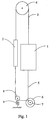
- Fig. 1 shows a traction sheave elevator according to the invention, comprising an elevator car 1 and a counterweight 2 travelling along guide rails in an elevator shaft and suspended on suspension ropes 3.
- the steel suspension ropes 3 are fixed to the top part of the elevator car 1 and passed via a diverting pulley 4 in the elevator shaft to the counterweight 2.
- the substantially round hoisting ropes 5 used to move the elevator car and counterweight, made of synthetic material, are flexible and substantially thin as compared with the suspension ropes.
- the hoisting ropes are attached by their first end to the lower part of the elevator car 1, from where the ropes are passed to the lower part of the counterweight 2 via the traction sheave 7 of a drive machine 6 placed on the bottom of the elevator shaft below the elevator car 1 and via a diverting pulley 8 placed on the bottom of the elevator shaft below the counterweight.
- the drive machine is e.g. a discoid electric motor of a flat construction in relation to its diameter, with a traction sheave integrated with the rotor and having a stator and rotor whose diameter is larger than the diameter of the traction sheave.
- the drive machine can be mounted either on the bottom of the shaft or on the shaft wall structures in the lower part of the elevator shaft.
- Several hoisting ropes running side by side can be used.
- the friction between the hoisting ropes and the traction sheave has been increased by having the hoisting ropes pass around the traction sheave 7 so that the hoisting ropes coming down from the elevator car pass between the diverting pulley 8 and the traction sheave 7 down to the traction sheave, run around the traction sheave by its lower side and then, having passed through a partial round about the traction sheave, go further by its upper side and intersect themselves, and after the intersection they go further to the diverting pulley 8, pass the diverting pulley by its lower side and go up to the counterweight.
- the hoisting ropes are attached to the lower part of the counterweight.
- the hoisting ropes are tensioned between the elevator car and the counterweight by means of the diverting pulley 8.
- the tensioning is implemented using a tension spring 9, which draws the traction sheave 8 so that the hoisting ropes always remain sufficiently tight on the traction sheave to provide the required friction regardless of elongation of the hoisting ropes.
- the tensioning can also be implemented using an arrangement in conjunction with the hoisting machinery, in which case the diverting pulley is fixedly mounted. In this case, the mass of the hoisting machinery can be utilised for the tensioning of the hoisting rope.
- the hoisting machinery is supported e.g. on the vertical guide rails in the elevator shaft and so connected that its mass will assist the rope tensioning elements.
- Fig. 2 presents a suspension arrangement that is better suited for a flat hoisting rope than the arrangement in Fig. 1 because the hoisting rope does not intersect itself.
- the hoisting ropes are suspended in the same way as in the solution presented in Fig. 1.
- Each hoisting rope 5 is attached by its first end to the lower part of the elevator car 1, from where the ropes are passed to the lower part of the counterweight 2 via the traction sheave 7 of a drive machine 6 placed on the bottom of the elevator shaft below the elevator car 1 and via a diverting pulley 8 placed on the bottom of the elevator shaft below the counterweight.
- the hoisting ropes are implemented in the same way as in Fig. 1, consisting of either a number of separate adjacent ropes or a single flat rope.
- the hoisting ropes descending from the elevator car go down to the traction sheave 7 by its back side as seen from the direction of the diverting pulley 8, pass around the traction sheave by its lower side and go further to the diverting pulley 8, pass around it by its lower side and go up to the counterweight.
- the angle of contact between the hoisting rope and the traction sheave is substantially smaller than in the solution presented in Fig. 1, in which it may be as large as over 270°. Therefore, the friction is also smaller, so the rope must be more tightly tensioned than in the case illustrated by Fig. 1. In other respects, the tensioning is implemented in the same way as in Fig. 1.
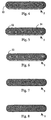
- Figures 3-6 present hoisting rope structures in which the load-bearing fibres are in strands.
- the strand layout is free and can be implemented either according to load capacity requirements or according to bending capacity, e.g. torsional rigidity.
- Fig. 3 presents a substantially flat elevator hoisting rope 5 as used in the suspension arrangement of the invention. It comprises six bundles 12a - 12e of strands fitted in the same plane. The bundles consist of load-bearing strands 13. These longitudinal strands, which form the strength of the rope structure, are made of synthetic fibres, e.g. aramid fibres. The strands are enclosed in a sheath 14 that binds the strands together into a single structure and gives a good friction coefficient in contact with the traction sheave. The bundles 12a - 12f are fitted side by side to form a planar sheath 14, so that the width of the rope is considerably larger than its thickness.
- the sheath material 14 may be e.g.
- the planar surface of the sheath can be coated with various materials.
- the properties of the coating 15 regarding friction and wear can be optimised for different traction sheave materials.
- the bundles of strands are of a round shape in cross-section, but naturally, the shape can be chosen in accordance with the use.
- Fig. 4 presents a flat hoisting rope solution in which the bundles 12 of strands are placed at different distances from each other. The Bundles are somewhat closer to each other near the edges than in the middle part of the hoisting rope.
- the bundles 12 of strands are placed non-symmetrically with respect to the longer midline of the hoisting rope, close to the friction surface of the rope.
- Fig. 6 presents a solution in which the strands and bundles 12 of strands of the hoisting rope are of different sizes in diameter. The larger bundles are placed at the edges of the rope as seen in its widthways direction, with smaller bundles placed between them.
- Figures 7 and 8 present hoisting rope solutions in which the load-bearing fibres are in the form of a fabric.
- the fibres form in the cross-section of the hoisting rope 5 lines crossing each other in both the longitudinal and lateral directions of the hoisting rope 5.
- the lines may also be in a position oblique to the longitudinal direction of the hoisting rope.
- the fabric may resemble e.g. the clinch-built, cross-ply structure of a car's safety belt or a corresponding belt.
- Fig. 8 presents a hoisting rope structure in which the hoisting rope in its entire cross-sectional area consists of fabric or fabrics bound together by a binding agent, e.g. polyurethane.
- the traction sheave is provided with a tilting mechanism and sensors monitoring the position of the rope edge.
- the traction sheave is a straight cylinder, whose axis of rotation can be tilted to bring the hoisting rope to the central part of the traction sheave.
- a mechanical sensor or an equivalent detector based on beam of light or the like gives a corresponding signal to the system controlling the tilting of the traction sheave, whereupon the tilt of the traction sheave is altered so that the band-like hoisting rope is brought back to the middle of the traction sheave.
- a cambered/crowned traction sheave or diverting pulley i.e. one with a varying diameter, in which case the circumferential surface of the sheave/pulley is either convex or concave as seen from the front of the sheave/pulley. The advantage achieved is a good retention of the hoisting rope in its proper position.
- the bundles 12a - 12f of strands are placed apart from each other, in which case they function like independent hoisting ropes regardless of the other bundles.
- the traction sheaves needed e.g. in the elevator suspension arrangements described above are considerably smaller in diameter and lighter than the traction sheaves currently used.
- the smaller traction sheave and machinery allow all elevator components to be accommodated in the elevator shaft, thus eliminating the need for a separate machine room. This brings considerable savings in the delivery price of the elevator.
- the elevator hoisting rope need not necessarily have a round or flat cross-sectional form. Instead, it may be e.g. a triangular-belt type rope having a V-shaped cross-section, in which case it is possible to achieve a very large friction between each hoisting rope and the corresponding keyway on the traction sheave.
- the suspension ropes can also be made of synthetic fibres and they may consist of either several adjacent ropes or only one flat rope.
- the bundles of strands can be arranged in more than one layer, e.g. in two layers, if necessary in view of the load to be borne by the rope.
- the suspension ratio may also be other than the 1:1 suspension presented in the example.
Claims (13)
- Ascenseur ayant un dispositif de câble d'ascenseur dans lequel une cabine d'ascenseur (1) et un contrepoids (2) circulent le long des rails de guidage dans une cage d'ascenseur sont supportés par des câbles de suspension (3) attachés à la partie supérieure de la cabine d'ascenseur (1) et passés via au moins une poulie de déviation (4) vers le contrepoids (2); et dans lequel ascenseur , en plus, au moins un câble de levage est attaché à la cabine d'ascenseur vers le contrepoids (2) par l'intermédiaire du disque de traction (7) d'une machine d'entraínement (6) par l'intermédiaire d'au moins une poulie de déviation (8) sous une tension agissant sur le câble de levage disposé dans la partie inférieure de la cage d'ascenseur , caractérisé en ce que le câble de levage (5) est constitué d'un matériau synthétique et a une forme de bande dont la largeur est essentiellement plus grande que son épaisseur.
- Ascenseur selon la revendication 1, caractérisé en ce que le câble de levage (5) est un câble essentiellement mince constitué de fibres synthétiques telle des fibres aramide et lequel câble a un matériau en plastique sous forme de gaine en polyuréthane.
- Ascenseur selon la revendication 1 ou 2, caractérisé en ce que le câble de levage (5) est un câble dans lequel les paquets (12a à 12f) de torons sont constitués de fibres synthétiques , par exemple de fibres aramide et la gaine (4) est fait d'un matériau en plastique tel du polyuréthane et en ce que les paquets (12a à 12f) ont été encastrés cote à cote dans au moins un plan pour former une couche de paquets de torons de sorte qu'en section transversale, le câble est essentiellement plus grande dans sa largeur que dans son épaisseur.
- Ascenseur selon la revendication 1 ou 2, caractérisé en ce que le câble de levage (5) consiste en des câbles adjacents dans lesquels les paquets (12a à 12f) de torons sont placés séparément l'un par rapport à l'autre de sorte que chaque paquet fonctionne en tant que câble indépendant.
- Câble de levage destiné à un ascenseur à disque de traction ; le câble étant désigné à s'engager dans avec le disque de traction de manière à recevoir le balourd entre le contrepoids et la cabine d'ascenseur avec son poids pour faire bouger ces composants , avec caractéristiques suivants :le câble est constitué d'un matériau synthétiquela force de tension de la structure du câble est formée par des fibres arrangés sous la forme de torons (13) ou sous la forme d'au moins un tissu et qui sont entourés par une gaine (14) qui lie ensemble les torons / fibres de chaque câblele câble (5) a une forme en bande ayant une largeur essentiellement plus grande que son épaisseur
- Câble de levage selon la revendication 5, dans lequel la gaine (14) est en polyuréthane.
- Câble de levage selon la revendication 5 ou 6, pour lequel la gaine (14) fournit un bon coefficient de friction contre le disque de traction.
- Câble de levage selon la revendication 5 ou 6, où une surface plane de la gaine (14) est recouverte avec une couche (15) d'un matériau résistant à l'usure ayant un bon coefficient de friction contre le matériau du disque de traction.
- Câble de levage selon une des revendications précédentes , où le câble comprend plusieurs paquets (12a à 12f) de torons (13) qui sont placés l'un éloigné de l'autre.
- Câble de levage selon une des revendications 8 à 9 , où les fibres sont disposés sous la forme d'un tissu.
- Câble de levage selon la revendication 10, où le tissu ressemble à une structure accrochée et pliée de façon croisée d'une ceinture .
- Câble de levage selon la revendication 10 ou 11, où les fibres forment dans la section transversale du câble de levage des lignes qui se croisent en direction longitudinale et latérale du câble de levage.
- Câble selon une des revendications précédentes, où les fibres sont faites d'aramide.
Applications Claiming Priority (5)
| Application Number | Priority Date | Filing Date | Title |
|---|---|---|---|
| FI965242A FI965242A0 (fi) | 1996-12-30 | 1996-12-30 | Hisslina |
| FI965243A FI103724B (fi) | 1996-12-30 | 1996-12-30 | Hissin köysijärjestely |
| FI965242 | 1996-12-30 | ||
| FI965243 | 1996-12-30 | ||
| PCT/FI1997/000824 WO1998029327A1 (fr) | 1996-12-30 | 1997-12-19 | Dispositif de cable d'ascenseur |
Publications (2)
| Publication Number | Publication Date |
|---|---|
| EP0948453A1 EP0948453A1 (fr) | 1999-10-13 |
| EP0948453B1 true EP0948453B1 (fr) | 2003-03-19 |
Family
ID=26160287
Family Applications (1)
| Application Number | Title | Priority Date | Filing Date |
|---|---|---|---|
| EP97948931A Expired - Lifetime EP0948453B1 (fr) | 1996-12-30 | 1997-12-19 | Dispositif de cable d'ascenseur |
Country Status (7)
| Country | Link |
|---|---|
| US (2) | US6364063B1 (fr) |
| EP (1) | EP0948453B1 (fr) |
| JP (1) | JP2001524060A (fr) |
| AU (1) | AU7890098A (fr) |
| DE (1) | DE69720044T2 (fr) |
| ES (1) | ES2189986T3 (fr) |
| WO (1) | WO1998029327A1 (fr) |
Cited By (4)
| Publication number | Priority date | Publication date | Assignee | Title |
|---|---|---|---|---|
| US9315363B2 (en) | 2000-12-08 | 2016-04-19 | Kone Corporation | Elevator and elevator rope |
| US9315938B2 (en) | 2001-06-21 | 2016-04-19 | Kone Corporation | Elevator with hoisting and governor ropes |
| US9446931B2 (en) | 2002-01-09 | 2016-09-20 | Kone Corporation | Elevator comprising traction sheave with specified diameter |
| US9573792B2 (en) | 2001-06-21 | 2017-02-21 | Kone Corporation | Elevator |
Families Citing this family (101)
| Publication number | Priority date | Publication date | Assignee | Title |
|---|---|---|---|---|
| FI119237B (fi) * | 2003-01-31 | 2008-09-15 | Kone Corp | Hissi, menetelmä hissin muodostamiseksi ja tasauslaitteiston käyttö |
| US6401871B2 (en) * | 1998-02-26 | 2002-06-11 | Otis Elevator Company | Tension member for an elevator |
| DE29924761U1 (de) | 1998-02-26 | 2005-06-23 | Otis Elevator Co., Farmington | Zugelement für einen Aufzug |
| PT1097101E (pt) * | 1998-02-26 | 2007-06-19 | Otis Elevator Co | Sistema de elevador que tem motor de accionamento localizado na porção inferior da via de elevação |
| DE69933199C5 (de) * | 1998-02-26 | 2014-07-24 | Otis Elevator Co. | Aufzugssystem mit einem zwischen der aufzugskabine und der schachtwand angeordneten antriebsmotor |
| US6397974B1 (en) | 1998-10-09 | 2002-06-04 | Otis Elevator Company | Traction elevator system using flexible, flat rope and a permanent magnet machine |
| US7299896B1 (en) | 1998-09-29 | 2007-11-27 | Otis Elevator Company | Elevator system having drive motor located adjacent to hoistway door |
| ES2285850T3 (es) * | 1998-02-26 | 2007-11-16 | Otis Elevator Company | Sistema de ascensor que tiene el motor de accionamiento situado en la parte inferior de la caja de ascensor. |
| ES2399413T5 (es) † | 1998-02-26 | 2022-06-07 | Otis Elevator Co | Sistema de ascensor de tracción que utiliza un cable flexible plano |
| US6860367B1 (en) | 1998-09-29 | 2005-03-01 | Otis Elevator Company | Elevator system having drive motor located below the elevator car |
| US6820726B1 (en) | 1998-12-22 | 2004-11-23 | Otis Elevator Company | Traction enhanced controlled pressure flexible flat tension member termination device |
| US6256841B1 (en) | 1998-12-31 | 2001-07-10 | Otis Elevator Company | Wedge clamp type termination for elevator tension member |
| DE29924775U1 (de) * | 1998-12-22 | 2005-07-07 | Otis Elevator Co., Farmington | Aufzugsystem |
| PT2284111E (pt) * | 1998-12-22 | 2013-07-19 | Otis Elevator Co | Elemento de tensão para um elevador |
| US7246688B2 (en) | 1998-12-23 | 2007-07-24 | Otis Elevator Company | Elevator door system |
| US6419208B1 (en) * | 1999-04-01 | 2002-07-16 | Otis Elevator Company | Elevator sheave for use with flat ropes |
| US6742769B2 (en) | 1999-04-01 | 2004-06-01 | Otis Elevator Company | Elevator sheave for use with flat ropes |
| IL136332A (en) * | 1999-06-11 | 2005-06-19 | Inventio Ag | Synthetic fiber rope |
| US6672046B1 (en) * | 1999-08-26 | 2004-01-06 | Otis Elevator Company | Tension member for an elevator |
| WO2001014630A1 (fr) * | 1999-08-26 | 2001-03-01 | Otis Elevator Company | Cable porteur d'ascenseur |
| US6295799B1 (en) | 1999-09-27 | 2001-10-02 | Otis Elevator Company | Tension member for an elevator |
| SG83818A1 (en) * | 1999-10-21 | 2001-10-16 | Inventio Ag | Rope deflection and suitable synthetic fiber rope and their use |
| US6484368B1 (en) | 2000-01-11 | 2002-11-26 | Otis Elevator Company | Flexible flat tension member termination device |
| US6345419B1 (en) | 2000-01-19 | 2002-02-12 | Otis Elevator Company | Termination for flat flexible tension member |
| DE50114535D1 (de) * | 2000-03-31 | 2009-01-15 | Inventio Ag | Mechanische Spannvorrichtung für Unterseil eines Aufzugs |
| AU2001278406A1 (en) | 2000-07-29 | 2002-02-13 | Alpha Getriebebau Gmbh | Elevator car with a driving pulley driving machine integrated therein |
| FR2813874B1 (fr) * | 2000-09-08 | 2003-01-31 | Sodimas | Installation d'ascenseur pourvue de moyens d'entrainement et de moyens de suspension independants |
| US6837340B2 (en) * | 2000-10-20 | 2005-01-04 | Datwyler Ag | Compensation weights and elevator systems |
| US6488123B2 (en) * | 2001-02-12 | 2002-12-03 | Otis Elevator Company | Directional uniformity of flat tension members for elevators |
| US6668980B2 (en) * | 2001-07-06 | 2003-12-30 | Thyssen Elevator Capital Corp. | Elevator car isolation system and method |
| US7670240B2 (en) * | 2001-10-04 | 2010-03-02 | Otis Elevator Company | Elevator belt assembly with noise reducing groove arrangement |
| US8444515B2 (en) * | 2001-11-13 | 2013-05-21 | Otis Elevator Company | Elevator belt assembly with noise and vibration reducing grooveless jacket arrangement |
| CA2465031C (fr) * | 2001-11-23 | 2011-05-10 | Inventio Ag | Ascenseur pourvu d'un moyen de transmission du type courroie, en particulier d'une courroie trapezoidale a nervures, servant de moyen de support et/ou de moyen d'entrainement |
| US20030121729A1 (en) * | 2002-01-02 | 2003-07-03 | Guenther Heinz | Lift belt and system |
| WO2003062117A1 (fr) * | 2002-01-16 | 2003-07-31 | Otis Elevator Company | Systeme d'ascenseur comprenant un ensemble courroie avec une configuration de rainures permettant de diminuer les vibrations et le bruit |
| US20040026676A1 (en) * | 2002-08-06 | 2004-02-12 | Smith Rory Stephen | Modular sheave assemblies |
| WO2004037702A1 (fr) * | 2002-10-25 | 2004-05-06 | Mitsubishi Denki Kabushiki Kaisha | Cordage pour ascenseur |
| US6966408B2 (en) | 2002-10-29 | 2005-11-22 | Thyssen Elevator Capital Corp. | Autobalance roping and drive arrangement |
| IL158256A (en) * | 2002-11-01 | 2010-02-17 | Inventio Ag | Rope of synthetic fibre |
| EP1416082B1 (fr) * | 2002-11-01 | 2010-06-23 | Inventio Ag | Câble en fibres synthétiques avec élément de renforcement pour le renforcement mécanique de la gaine |
| WO2004043843A1 (fr) * | 2002-11-12 | 2004-05-27 | Mitsubishi Denki Kabushiki Kaisha | Cable pour ascenseur et equipement d'ascenseur |
| DE10300992A1 (de) * | 2003-01-14 | 2004-07-22 | Aufzugswerke M. Schmitt & Sohn Gmbh & Co. | Aufzug mit getrennter Fahrkorbaufhängung |
| US7395899B2 (en) | 2003-01-27 | 2008-07-08 | Exterior Elevator, Llc | Method and apparatus for reaching from outside an upper level of a tall structure |
| US20060225965A1 (en) | 2003-04-22 | 2006-10-12 | Siewert Bryan R | Elevator system without a moving counterweight |
| US7946390B2 (en) * | 2003-05-30 | 2011-05-24 | Otis Elevator Company | Tie-down compensation for an elevator system |
| WO2005047724A2 (fr) * | 2003-11-14 | 2005-05-26 | University Of Maryland, Baltimore County | Systeme et procede permettant d'amortir les vibrations dans des cables d'ascenseur |
| US7793763B2 (en) * | 2003-11-14 | 2010-09-14 | University Of Maryland, Baltimore County | System and method for damping vibrations in elevator cables |
| FI119020B (fi) * | 2003-11-24 | 2008-06-30 | Kone Corp | Hissi ja menetelmä nostoköysistön hallitsemattoman löystymisen ja/tai tasauslaitteen hallitsemattoman liikkeen estämiseksi |
| US7537087B2 (en) * | 2004-01-23 | 2009-05-26 | Exterior Elevator, Llc | Method and apparatus for reaching from outside an upper level of a tall structure |
| WO2006043317A1 (fr) * | 2004-10-20 | 2006-04-27 | Mitsubishi Denki Kabushiki Kaisha | Appareillage d'ascenseur |
| CN100522784C (zh) * | 2004-11-29 | 2009-08-05 | 三菱电机株式会社 | 无对重电梯装置 |
| JP2006335568A (ja) * | 2005-06-02 | 2006-12-14 | Inventio Ag | せん断力を許容することができ数本のケーブルを接続する接続部を有する支持手段 |
| NO20063896L (no) * | 2005-09-20 | 2007-03-21 | Inventio Ag | Heisanlegg med drivremskive og flatremformet baereorgan |
| KR100882109B1 (ko) * | 2005-10-07 | 2009-02-06 | 오티스 엘리베이터 컴파니 | 이동 평형추가 없는 승강기 시스템 |
| KR101084352B1 (ko) * | 2005-11-02 | 2011-11-16 | 오티스 엘리베이터 컴파니 | 상이한 크기의 부하 지지 부재들을 포함하는 엘리베이터 부하 지지 조립체 |
| WO2007061376A1 (fr) * | 2005-11-25 | 2007-05-31 | Abb Ab | Procédé pour augmenter la durée de vie de câbles de tête pour des treuils d'extraction minière à frottement de transport unique pour des puits profonds |
| KR100824501B1 (ko) * | 2006-07-24 | 2008-04-22 | 미쓰비시덴키 가부시키가이샤 | 균형추 없는 엘리베이터 장치 |
| KR100792092B1 (ko) * | 2006-09-28 | 2008-01-04 | 미쓰비시덴키 가부시키가이샤 | 엘리베이터 장치 |
| WO2009041970A1 (fr) * | 2007-09-27 | 2009-04-02 | Otis Elevator Company | Élément de support de charge d'ascenseur |
| WO2009050182A2 (fr) | 2007-10-17 | 2009-04-23 | Inventio Ag | Ascenseur avec un moyen de support |
| GB2458001B (en) | 2008-01-18 | 2010-12-08 | Kone Corp | An elevator hoist rope, an elevator and method |
| FI125134B (fi) * | 2010-04-12 | 2015-06-15 | Kone Corp | Hissi |
| WO2011133872A2 (fr) | 2010-04-22 | 2011-10-27 | Thyssenkrupp Elevator Ag | Suspension d'ascenseur et bande de transmission |
| FI125113B (fi) * | 2010-04-30 | 2015-06-15 | Kone Corp | Hissi |
| FI124541B (fi) * | 2011-05-18 | 2014-10-15 | Kone Corp | Hissijärjestely |
| FI125114B (fi) | 2011-09-15 | 2015-06-15 | Kone Corp | Hissin ripustus- ja ohjainjärjestely |
| FI125157B (fi) * | 2011-11-08 | 2015-06-15 | Kone Corp | Hissijärjestelmä |
| JP5859138B2 (ja) * | 2011-11-10 | 2016-02-10 | オーチス エレベータ カンパニーOtis Elevator Company | エレベータシステムベルト |
| FI20116190L (fi) * | 2011-11-28 | 2013-05-29 | Kone Corp | Hissijärjestely ja menetelmä |
| FI20125078L (fi) * | 2012-01-25 | 2013-07-26 | Kone Corp | Hissi |
| FI125329B (fi) * | 2012-01-27 | 2015-08-31 | Kone Corp | Järjestely hissin tasauspainojohteiden kiinnittämiseksi ja järjestelyssä käytettävä johdekiinnike |
| EP2875182B1 (fr) * | 2012-07-18 | 2020-07-01 | Otis Elevator Company | Courroie ignifuge |
| FI125459B (fi) * | 2012-10-31 | 2015-10-15 | Kone Corp | Hissin vetohihnan kiristysjärjestelmä ja hissi |
| WO2014076370A1 (fr) * | 2012-11-16 | 2014-05-22 | Kone Corporation | Ascenseur, et amélioration apportée à la réduction de l'allongement de câble ou courroie d'ascenseur dans une situation de charge de la cabine d'ascenseur, et utilisation de contrainte de tension préalable pour renforcer le câble ou la courroie de l'ascenseur |
| EP2749519B1 (fr) * | 2012-12-27 | 2020-07-22 | KONE Corporation | Ascenseur avec une courroie comprenant fibres non métalliques. |
| FI124543B (en) * | 2012-12-30 | 2014-10-15 | Kone Corp | Rope clamp assembly and elevator |
| FI124242B (en) * | 2013-02-12 | 2014-05-15 | Kone Corp | Arrangements for dampening lateral oscillations of a line-like equipment attached to a lift unit and elevator |
| US9321616B2 (en) | 2013-03-14 | 2016-04-26 | Marvin M. May | Lifting systems |
| US10301151B2 (en) | 2013-03-15 | 2019-05-28 | Otis Elevator Company | Traction sheave for elevator system |
| EP2868613B1 (fr) * | 2013-11-05 | 2019-05-15 | KONE Corporation | Ascenseur |
| EP2886500B1 (fr) * | 2013-12-17 | 2021-06-16 | KONE Corporation | Ascenseur |
| CN104724577A (zh) * | 2013-12-18 | 2015-06-24 | 黄立成 | 带有兼具信号传输和曳引传动的牵引构件的电梯系统 |
| WO2015134025A1 (fr) | 2014-03-06 | 2015-09-11 | Otis Elevator Company | Courroie élévatrice renforcée de fibres et son procédé de fabrication |
| FI126805B (fi) * | 2014-03-24 | 2017-05-31 | Kone Corp | Vetoelimen kireyttä valvovalla laitteistolla varustettu hissi |
| US9346656B2 (en) | 2014-07-01 | 2016-05-24 | Marvin M. May | Stabilization and control of a crane load |
| EP2990370B1 (fr) * | 2014-09-01 | 2017-06-14 | KONE Corporation | Ascenseur |
| CN104444729A (zh) * | 2014-11-04 | 2015-03-25 | 黄立成 | 三位一体的电梯曳引系统 |
| EP3242849B1 (fr) * | 2015-01-09 | 2020-07-01 | Otis Elevator Company | Élément de support de charge pour système |
| EP3288887A4 (fr) * | 2015-04-27 | 2019-03-13 | KONE Corporation | Agencement d'ajustement de tension d'un élément de traction d'un ascenseur |
| EP3135621B1 (fr) * | 2015-08-31 | 2018-06-13 | KONE Corporation | Procédé, dispositif et ascenseur |
| WO2017129851A1 (fr) * | 2016-01-25 | 2017-08-03 | Kone Corporation | Agencement pour appareil de levage d'ascenseur |
| US10556775B2 (en) | 2016-02-09 | 2020-02-11 | Otis Elevator Company | Surface construction of elevator belt |
| EP3279130A1 (fr) * | 2016-08-01 | 2018-02-07 | KONE Corporation | Grille de roue de poulie |
| WO2018077654A1 (fr) * | 2016-10-31 | 2018-05-03 | Inventio Ag | Installation d'ascenseur comprenant une courroie extraite servant d'élément de compensation pour la compensation du poids propre du moyen de suspension |
| KR102518963B1 (ko) | 2016-12-12 | 2023-04-07 | 오티스 엘리베이터 컴파니 | 엘리베이터 시스템용 하이브리드 직물-라미네이트된 벨트 |
| AU2018202726B2 (en) * | 2017-04-20 | 2023-09-28 | Otis Elevator Company | Elevator system belt with fabric tension member |
| WO2018198240A1 (fr) * | 2017-04-26 | 2018-11-01 | 三菱電機株式会社 | Ascenseur, corps de suspension associé, et procédé de production de corps de suspension |
| US10858780B2 (en) | 2018-07-25 | 2020-12-08 | Otis Elevator Company | Composite elevator system tension member |
| US11655120B2 (en) * | 2019-06-28 | 2023-05-23 | Otis Elevator Company | Elevator load bearing member including a unidirectional weave |
| JP7357803B2 (ja) * | 2020-08-27 | 2023-10-06 | 三菱電機株式会社 | ベルト、その製造方法、及びエレベーター |
| JP7448100B1 (ja) | 2022-05-18 | 2024-03-12 | 三菱電機株式会社 | ロープシステム |
Family Cites Families (42)
| Publication number | Priority date | Publication date | Assignee | Title |
|---|---|---|---|---|
| US657380A (en) * | 1898-02-04 | 1900-09-04 | Otis Elevator Co | Elevator. |
| US811513A (en) * | 1902-06-23 | 1906-01-30 | Elevator Securities Company | Elevator. |
| US1011423A (en) * | 1908-03-27 | 1911-12-12 | Otis Elevator Co | Belt-drive elevator. |
| US975790A (en) * | 1908-11-25 | 1910-11-15 | Charles O Pearson | Multiple metallic belt for traction-elevators. |
| US1035230A (en) * | 1911-10-24 | 1912-08-13 | Charles O Pearson | Traction-elevator. |
| US1071309A (en) * | 1912-08-09 | 1913-08-26 | Byron R Goggin | Elevator-operating mechanism. |
| US3174585A (en) * | 1962-08-13 | 1965-03-23 | Otis Elevator Co | Elevator hoisting mechanism |
| JPS4920811B1 (fr) * | 1967-12-04 | 1974-05-28 | ||
| US3910383A (en) * | 1974-04-22 | 1975-10-07 | Vladimir Friedl | Manlift |
| US3911755A (en) * | 1974-10-17 | 1975-10-14 | Gates Rubber Co | Flat belt |
| DE2455273C3 (de) * | 1974-11-22 | 1978-01-19 | Feiten & Guilleaume Carlswerk AG, 5000 Köln | Kranseil aus Kunststoff |
| JPS593011B2 (ja) * | 1978-05-23 | 1984-01-21 | 株式会社フジクラ | 平型給電ケ−ブル |
| JPS5826515A (ja) * | 1981-08-05 | 1983-02-17 | 三菱電機株式会社 | エレベ−タケ−ブルの重ね吊り布設方法 |
| US4716989A (en) * | 1982-08-04 | 1988-01-05 | Siecor Corporation | Elevator compensating cable |
| US4445593A (en) * | 1982-10-15 | 1984-05-01 | Siecor Corporation | Flat type feeder cable |
| US4624097A (en) * | 1984-03-23 | 1986-11-25 | Greening Donald Co. Ltd. | Rope |
| EP0179648A1 (fr) * | 1984-10-23 | 1986-04-30 | Marcelo Luis Dodero | Structure d'un câble électrique plat |
| JPS61193305A (ja) * | 1985-02-22 | 1986-08-27 | 日立電線株式会社 | 平型エレベ−タケ−ブル |
| US5149057A (en) * | 1989-03-09 | 1992-09-22 | Baker Hughes Incorporated | Tape drive with self-expanding coils for sludge collector |
| JPH031409A (ja) * | 1989-05-30 | 1991-01-08 | Fujikura Ltd | エレベータ用平型ケーブル |
| JPH03176912A (ja) * | 1989-12-05 | 1991-07-31 | Hitachi Cable Ltd | 平形エレベータケーブル |
| US4990125A (en) * | 1990-01-12 | 1991-02-05 | The Gates Rubber Company | Flat belt, belt drive, and method |
| JPH04201966A (ja) * | 1990-10-22 | 1992-07-22 | Mitsubishi Electric Corp | エレベータ用移動ケーブル |
| DE9201374U1 (fr) * | 1992-02-05 | 1992-04-02 | C. Haushahn Gmbh & Co, 7000 Stuttgart, De | |
| US5253318A (en) * | 1992-02-14 | 1993-10-12 | W. L. Gore & Associates, Inc. | Optical fiber ribbon cable |
| JPH0644829A (ja) * | 1992-07-24 | 1994-02-18 | Mitsubishi Cable Ind Ltd | エレベータ用平型ケーブルおよびその製造方法 |
| JP2536816B2 (ja) * | 1994-02-25 | 1996-09-25 | 光洋自動機株式会社 | 昇降装置 |
| CZ282660B6 (cs) | 1994-03-02 | 1997-08-13 | Inventio Ag | Nosné lano zdvihacích a přepravních prostředků |
| US5516986A (en) * | 1994-08-26 | 1996-05-14 | Peterson; Edwin P. | Miniature electric cable |
| CA2169431C (fr) * | 1995-03-06 | 2005-07-12 | Claudio De Angelis | Materiel servant a indiquer quand des cables a fibres synthetiques doivent etre mis au rebut |
| US5881843A (en) * | 1996-10-15 | 1999-03-16 | Otis Elevator Company | Synthetic non-metallic rope for an elevator |
| US5931265A (en) * | 1997-03-27 | 1999-08-03 | Otis Elevator Company | Rope climbing elevator |
| US5881845A (en) * | 1997-05-05 | 1999-03-16 | Otis Elevator Comany | Elevator rope protective device |
| ES2244176T3 (es) * | 1998-02-26 | 2005-12-01 | Otis Elevator Company | Sistema de ascenso con motor de accionamiento situado adyacente a puerta de la caja del ascensor. |
| US6138799A (en) * | 1998-09-30 | 2000-10-31 | Otis Elevator Company | Belt-climbing elevator having drive in counterweight |
| BR9908230A (pt) * | 1998-02-26 | 2000-10-31 | Otis Elevador Company | Sistema de elevador com motor de acionamento suspenso |
| WO1999043590A1 (fr) * | 1998-02-26 | 1999-09-02 | Otis Elevator Company | Systeme d'ascenseur a traction dans lequel un cable plat et souple ainsi qu'une machinerie a aimants permanents sont utilises |
| DE29924761U1 (de) * | 1998-02-26 | 2005-06-23 | Otis Elevator Co., Farmington | Zugelement für einen Aufzug |
| WO1999043599A1 (fr) * | 1998-02-26 | 1999-09-02 | Otis Elevator Company | Systeme d'ascenseur a mecanisme d'entrainement de tambour utilisant une courroie plate |
| ES2196781T3 (es) * | 1998-02-26 | 2003-12-16 | Otis Elevator Co | Sistema de ascensor sin cuarto de maquinas con una maquina elevadora montada sobre una cabina. |
| ES2285850T3 (es) * | 1998-02-26 | 2007-11-16 | Otis Elevator Company | Sistema de ascensor que tiene el motor de accionamiento situado en la parte inferior de la caja de ascensor. |
| US6305499B1 (en) * | 1998-09-30 | 2001-10-23 | Otis Elevator Company | Drum drive elevator using flat belt |
-
1997
- 1997-12-19 ES ES97948931T patent/ES2189986T3/es not_active Expired - Lifetime
- 1997-12-19 JP JP52965598A patent/JP2001524060A/ja active Pending
- 1997-12-19 DE DE69720044T patent/DE69720044T2/de not_active Expired - Lifetime
- 1997-12-19 AU AU78900/98A patent/AU7890098A/en not_active Abandoned
- 1997-12-19 EP EP97948931A patent/EP0948453B1/fr not_active Expired - Lifetime
- 1997-12-19 WO PCT/FI1997/000824 patent/WO1998029327A1/fr active IP Right Grant
-
1999
- 1999-06-22 US US09/337,739 patent/US6364063B1/en not_active Expired - Lifetime
-
2002
- 2002-02-27 US US10/083,377 patent/US6868661B2/en not_active Expired - Lifetime
Cited By (4)
| Publication number | Priority date | Publication date | Assignee | Title |
|---|---|---|---|---|
| US9315363B2 (en) | 2000-12-08 | 2016-04-19 | Kone Corporation | Elevator and elevator rope |
| US9315938B2 (en) | 2001-06-21 | 2016-04-19 | Kone Corporation | Elevator with hoisting and governor ropes |
| US9573792B2 (en) | 2001-06-21 | 2017-02-21 | Kone Corporation | Elevator |
| US9446931B2 (en) | 2002-01-09 | 2016-09-20 | Kone Corporation | Elevator comprising traction sheave with specified diameter |
Also Published As
| Publication number | Publication date |
|---|---|
| ES2189986T3 (es) | 2003-07-16 |
| US6364063B1 (en) | 2002-04-02 |
| EP0948453A1 (fr) | 1999-10-13 |
| DE69720044D1 (de) | 2003-04-24 |
| US6868661B2 (en) | 2005-03-22 |
| DE69720044T2 (de) | 2003-09-11 |
| JP2001524060A (ja) | 2001-11-27 |
| US20020092285A1 (en) | 2002-07-18 |
| AU7890098A (en) | 1998-07-31 |
| WO1998029327A1 (fr) | 1998-07-09 |
Similar Documents
| Publication | Publication Date | Title |
|---|---|---|
| EP0948453B1 (fr) | Dispositif de cable d'ascenseur | |
| WO1998029326A1 (fr) | Dispositif de cable d'ascenseur | |
| KR100977728B1 (ko) | 소형 구동 기어를 구비한 엘리베이터 | |
| JP4391640B2 (ja) | より合成繊維ロープ | |
| EP1066213B1 (fr) | Systeme ascenseur avec le moteur d'entrainement monté en haut | |
| AU2013270591B2 (en) | An elevator | |
| RU2492130C2 (ru) | Тонкая высокопрочная проволока для подъемного каната лифта | |
| RU2352514C2 (ru) | Лифт | |
| KR101088325B1 (ko) | 마찰 결합 동력 전달을 위한 보강재를 갖는 합성 섬유 로프 및 확실한 결합 동력 전달을 위한 보강재를 갖는 합성 섬유 로프 | |
| NO332403B1 (no) | Heis med en remlignende overforingsinnretning, spesielt med en kile-ribberem som fungerer som baere- og/eller drivinnretning | |
| EP1056679B1 (fr) | Systeme d'ascenseur exempt de local de machinerie, la machinerie etant montee sur la cabine d'ascenseur | |
| EP1056675A1 (fr) | Systeme d'ascenseur dont le moteur d'entrainement est situe entre la cabine d'ascenseur et la paroi lateral de la cage d'ascenseur | |
| US9873594B2 (en) | Elevator | |
| EP1097101B1 (fr) | Systeme d'ascenseur presentant un moteur d'entrainement situe au niveau de la portion inferieure de la cage d'ascenseur | |
| EP1911715B1 (fr) | Système élévateur dont le moteur d'entraînement est situé dans la partie inférieure du puits | |
| CN104418214B (zh) | 电梯 | |
| EP1676807B1 (fr) | Systeme d'ascenseur avec moteur d'entrainement monté en haut de la gaine | |
| FI103724B (fi) | Hissin köysijärjestely | |
| FI110507B (fi) | Hissin köysijärjestely |
Legal Events
| Date | Code | Title | Description |
|---|---|---|---|
| PUAI | Public reference made under article 153(3) epc to a published international application that has entered the european phase |
Free format text: ORIGINAL CODE: 0009012 |
|
| 17P | Request for examination filed |
Effective date: 19990730 |
|
| AK | Designated contracting states |
Kind code of ref document: A1 Designated state(s): CH DE ES FR GB LI |
|
| GRAG | Despatch of communication of intention to grant |
Free format text: ORIGINAL CODE: EPIDOS AGRA |
|
| GRAG | Despatch of communication of intention to grant |
Free format text: ORIGINAL CODE: EPIDOS AGRA |
|
| GRAH | Despatch of communication of intention to grant a patent |
Free format text: ORIGINAL CODE: EPIDOS IGRA |
|
| 17Q | First examination report despatched |
Effective date: 20020627 |
|
| GRAH | Despatch of communication of intention to grant a patent |
Free format text: ORIGINAL CODE: EPIDOS IGRA |
|
| GRAA | (expected) grant |
Free format text: ORIGINAL CODE: 0009210 |
|
| AK | Designated contracting states |
Designated state(s): CH DE ES FR GB LI |
|
| REG | Reference to a national code |
Ref country code: GB Ref legal event code: FG4D |
|
| REG | Reference to a national code |
Ref country code: CH Ref legal event code: NV Representative=s name: ABACUS PATENTANWAELTE KLOCKE SPAETH BARTH Ref country code: CH Ref legal event code: EP |
|
| REF | Corresponds to: |
Ref document number: 69720044 Country of ref document: DE Date of ref document: 20030424 Kind code of ref document: P |
|
| REG | Reference to a national code |
Ref country code: ES Ref legal event code: FG2A Ref document number: 2189986 Country of ref document: ES Kind code of ref document: T3 |
|
| ET | Fr: translation filed | ||
| PLBE | No opposition filed within time limit |
Free format text: ORIGINAL CODE: 0009261 |
|
| STAA | Information on the status of an ep patent application or granted ep patent |
Free format text: STATUS: NO OPPOSITION FILED WITHIN TIME LIMIT |
|
| 26N | No opposition filed |
Effective date: 20031222 |
|
| REG | Reference to a national code |
Ref country code: FR Ref legal event code: PLFP Year of fee payment: 19 |
|
| PGFP | Annual fee paid to national office [announced via postgrant information from national office to epo] |
Ref country code: CH Payment date: 20151221 Year of fee payment: 19 |
|
| PGFP | Annual fee paid to national office [announced via postgrant information from national office to epo] |
Ref country code: ES Payment date: 20151214 Year of fee payment: 19 Ref country code: FR Payment date: 20151221 Year of fee payment: 19 |
|
| PGFP | Annual fee paid to national office [announced via postgrant information from national office to epo] |
Ref country code: GB Payment date: 20161222 Year of fee payment: 20 Ref country code: DE Payment date: 20161213 Year of fee payment: 20 |
|
| REG | Reference to a national code |
Ref country code: CH Ref legal event code: PL |
|
| REG | Reference to a national code |
Ref country code: FR Ref legal event code: ST Effective date: 20170831 |
|
| PG25 | Lapsed in a contracting state [announced via postgrant information from national office to epo] |
Ref country code: LI Free format text: LAPSE BECAUSE OF NON-PAYMENT OF DUE FEES Effective date: 20161231 Ref country code: FR Free format text: LAPSE BECAUSE OF NON-PAYMENT OF DUE FEES Effective date: 20170102 Ref country code: CH Free format text: LAPSE BECAUSE OF NON-PAYMENT OF DUE FEES Effective date: 20161231 |
|
| REG | Reference to a national code |
Ref country code: DE Ref legal event code: R071 Ref document number: 69720044 Country of ref document: DE |
|
| REG | Reference to a national code |
Ref country code: GB Ref legal event code: PE20 Expiry date: 20171218 |
|
| PG25 | Lapsed in a contracting state [announced via postgrant information from national office to epo] |
Ref country code: GB Free format text: LAPSE BECAUSE OF EXPIRATION OF PROTECTION Effective date: 20171218 |
|
| REG | Reference to a national code |
Ref country code: ES Ref legal event code: FD2A Effective date: 20180507 |
|
| PG25 | Lapsed in a contracting state [announced via postgrant information from national office to epo] |
Ref country code: ES Free format text: LAPSE BECAUSE OF FAILURE TO SUBMIT A TRANSLATION OF THE DESCRIPTION OR TO PAY THE FEE WITHIN THE PRESCRIBED TIME-LIMIT Effective date: 20030319 |
|
| PG25 | Lapsed in a contracting state [announced via postgrant information from national office to epo] |
Ref country code: ES Free format text: LAPSE BECAUSE OF FAILURE TO SUBMIT A TRANSLATION OF THE DESCRIPTION OR TO PAY THE FEE WITHIN THE PRESCRIBED TIME-LIMIT Effective date: 20161220 |
|
| RIC2 | Information provided on ipc code assigned after grant |
Ipc: B66B 11/08 20060101ALI19981015BHEP Ipc: B66B 7/06 20060101AFI19981015BHEP |