EP1097101B1 - Systeme d'ascenseur presentant un moteur d'entrainement situe au niveau de la portion inferieure de la cage d'ascenseur - Google Patents
Systeme d'ascenseur presentant un moteur d'entrainement situe au niveau de la portion inferieure de la cage d'ascenseur Download PDFInfo
- Publication number
- EP1097101B1 EP1097101B1 EP99936068A EP99936068A EP1097101B1 EP 1097101 B1 EP1097101 B1 EP 1097101B1 EP 99936068 A EP99936068 A EP 99936068A EP 99936068 A EP99936068 A EP 99936068A EP 1097101 B1 EP1097101 B1 EP 1097101B1
- Authority
- EP
- European Patent Office
- Prior art keywords
- hoistway
- sheave
- elevator
- rope
- elevator car
- Prior art date
- Legal status (The legal status is an assumption and is not a legal conclusion. Google has not performed a legal analysis and makes no representation as to the accuracy of the status listed.)
- Expired - Lifetime
Links
Images


Classifications
-
- B—PERFORMING OPERATIONS; TRANSPORTING
- B66—HOISTING; LIFTING; HAULING
- B66B—ELEVATORS; ESCALATORS OR MOVING WALKWAYS
- B66B11/00—Main component parts of lifts in, or associated with, buildings or other structures
- B66B11/0065—Roping
- B66B11/008—Roping with hoisting rope or cable operated by frictional engagement with a winding drum or sheave
- B66B11/009—Roping with hoisting rope or cable operated by frictional engagement with a winding drum or sheave with separate traction and suspension ropes
-
- B—PERFORMING OPERATIONS; TRANSPORTING
- B66—HOISTING; LIFTING; HAULING
- B66B—ELEVATORS; ESCALATORS OR MOVING WALKWAYS
- B66B7/00—Other common features of elevators
- B66B7/06—Arrangements of ropes or cables
- B66B7/10—Arrangements of ropes or cables for equalising rope or cable tension
Definitions
- the present invention relates generally to an elevator system, and more particularly to an elevator system including a drive motor located in the hoistway below the elevator car.
- Elevator systems have been developed to avoid the expense of a machine room. These elevator systems are difficult to install and maintain because hoistway access can be difficult or dangerous especially to maintenance people while working in the hoistway on machinery that controls elevator motion if the machinery, such as the drive motor, is located in a space between the elevator car and a sidewall of the hoistway. Furthermore, elevator systems typically require additional hoistway space to accommodate machinery disposed between the car and sidewall of the hoistway.
- WO 98/19327 discloses an elevator system having the features of the preamble of claim 1.
- An elevator system in accordance with the present invention is defined in claim1.
- An advantage of the present invention is that the elevator system significantly reduces the space and construction costs compared with an elevator system having a machine room.
- a second advantage of the present invention is that the hoistway dimensions can be kept to a minimum because the drive motor does not encroach into the hoistway space between the elevator car and a sidewall of the hoistway.
- a third advantage of the present invention is simplified and safe access to the drive motor and associated equipment from the elevator pit.
- a fourth advantage of the present invention is that flat rope technology reduces the size of the drive motor and sheaves, and thereby reduces the pit space required for accommodating the motor and sheaves.
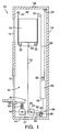
- an elevator system is generally designated by the reference number 10.
- the elevator system 10 includes a hoistway 12 defined by a surrounding structure 14, such as a building.
- the hoistway 12 includes door openings at each level along the hoistway for accepting hoistway doors 16,16.
- An elevator car 18 is provided in the hoistway 12 for upward and downward movement along the hoistway via conventional elevator guide rails (not shown).
- a counterweight 20 movably coupled to conventional counterweight guide rails (not shown) is located at a side of the hoistway 12 in a space extending along the length of the hoistway between the elevator car 18 and the sidewall 14 of the hoistway for balancing the elevator car during its upward and downward movement along the hoistway.
- the elevator system 10 includes at least one flat, suspension rope or belt 22 for supporting the weight of the elevator car 18 and the counterweight 20.
- the suspension rope 22 may be made of steel, non-metallic fiber or any other suitably strong material to support the elevator car 18 and the counterweight 20 during movement and acceleration of the elevator car and the counterweight along the hoistway 12.
- flat ropes or belts permit smaller drive motors and sheaves to drive and suspend elevator car and counterweight loads relative to drive motors and sheaves using conventional round ropes.
- the diameter of drive sheaves used in elevators with conventional round ropes is limited to 40 times the diameter of the ropes, or larger, due to fatigue of the ropes as they repeatedly conform to the diameter of the sheave and straighten out.
- Torque is proportional to the diameter of the traction sheave. Therefore, the use of a smaller diameter traction sheave reduces motor torque.
- Motor size (rotor volume) is roughly proportional to torque; therefore, although the mechanical output power remains the same regardless of sheave size, flat ropes or belts allow the use of a smaller drive motor operating at a higher speed relative to systems using conventional round ropes. Consequently, smaller conventional and flat drive motors may be accommodated in the hoistway pit which significantly reduces the size and construction cost of the hoistway pit.
- reducing the machine size i.e., drive motor and sheaves
- the smaller machine reduces the hoistway pit space requirement when the machine is located below the elevator car.
- a small machine utilizes less material, and will be less costly to produce relative to a larger machine.
- the light weight of a small machine reduces the time for handling the machine and the need for equipment to lift the machine into place so as to significantly reduce installation cost.
- low torque and high speed allow the elimination of gears, which are costly. Further, gears can cause vibrations and noise, and require maintenance of lubrication.
- geared machines may be employed if desired.
- Flat ropes or belts also distribute the elevator and counterweight loads over a greater surface area on the sheaves relative to round ropes for reduced specific pressure on the ropes, thus increasing its operating life.
- the flat ropes or belts may be made from a high traction material such as urethane or rubber jacket with fiber or steel reinforcement.
- the suspension rope 22 is attached at a first end to a first bracket 24 which is fixedly coupled within an upper portion of the hoistway 12, such as to a sidewall 26 or ceiling 28 of the hoistway.
- the suspension rope 22 extends downwardly from its first end, loops generally 90° about a first elevator sheave 30 coupled underneath and at one side of the elevator car 18, extends generally horizontally to a second elevator sheave 32 coupled underneath and at an opposite side of the elevator car, loops generally 90° about the second elevator sheave 32, extends upwardly and loops generally 180° about a first deflector sheave 34 fixedly coupled within an upper portion of the hoistway, such as to the sidewall 26 or the ceiling 28 of the hoistway 12, extends downwardly and loops generally 180° about a counterweight sheave 36 coupled to a top portion of the counterweight 20, and extends upwardly and is coupled at a second end within an upper portion of the hoistway, such as to the sidewall or ceiling of the hoistway via a second bracket 37.
- the elevator system 10 includes a drive motor 38 having a drive sheave 40 for moving the elevator car 18 and the counterweight 20 upwardly and downwardly along the hoistway 12 via at least one flat, drive rope or belt 42.
- the drive rope 42 may be made of steel, non-metallic fiber or any other suitably strong material to support the weight of imbalance between the elevator car 18 and the counterweight 20.
- the drive motor 38 is coupled to and supported by a sidewall or floor 44 of the hoistway 12 within a hoistway pit 46. As shown in FIG.
- the drive rope 42 is coupled at a first end to a lower portion 48 of the counterweight 20, extends downwardly and loops generally 90° about the drive sheave 40, extends generally horizontally and loops generally 90° about a second deflector sheave 49, and extends upwardly and is coupled at a second end to an underside 50 of the elevator car 18. Because the drive motor 38 is located below the elevator car 18 in the hoistway pit 46, the elevator system 10 avoids the additional expense and space associated with constructing and maintaining a machine room.
- the drive rope 42 may also be employed in a "double wrap traction" configuration.
- the drive rope 42 is coupled at its first end to the lower portion 48 of the counterweight 20, extends downwardly and loops generally 90° about the drive sheave 40, extends generally horizontally and loops generally 180° about the second deflector sheave 49, extends generally horizontally as shown by the dashed line 52 and loops generally 180° about the drive sheave 40, extends generally horizontally and loops generally 90° about the second deflector sheave 49, and extends upwardly and is coupled at its second end to the underside 50 of the elevator car 18.
- the suspension rope 22 and the drive rope 42 are separate and independent from one another.
- an elongated rigid connector 54 is pivotally coupled at a first end 55 to a rotational axis of the drive sheave 40 and at a second end 57 to a weight 56 which is suspended from a lower portion of the hoistway 12, such as a sidewall 58 of the hoistway via a tension spring 60.
- the rigid connector 54 is also coupled at 59 between its first and second ends 55, 57 to a rotational axis of the second deflector sheave 49.
- the weight 56 imparts a downward force to the second end 57 of the rigid connector 54 which pivots the rigid connector downwardly about its first end 55, and in turn moves the second deflector sheave 49 downwardly in order to provide tension in the drive rope 42 between the second deflector sheave 49 and the elevator car 18.
- the rigid connector 54, the weight 56, and the tension spring 60 cooperate as a tension applying mechanism for maintaining the drive rope 42 in a taut condition.
- the elevator system 10 tolerates large imbalances in the tension of the drive rope 42 between the elevator side and the counterweight side of the elevator system.
- This traction relation value of "23.14” means that t 1 /t 2 must be greater than 23.14 before the drive rope 42 begins to slip on the drive sheave 40 and the second deflector sheave 49, where t 1 is the tension in the portion of the drive rope 42 between the second deflector sheave 49 and the elevator car 18; and t 2 is the tension in the drive rope between the drive sheave 40 and the counterweight 20.
- t 1 is the tension in the portion of the drive rope 42 between the second deflector sheave 49 and the elevator car 18
- t 2 is the tension in the drive rope between the drive sheave 40 and the counterweight 20.
- the drive motor 38 is signaled by a controller (not shown) to rotate the drive sheave 40 counterclockwise in order to move the elevator car 18 downwardly along the hoistway 12.
- the rotating drive sheave 40 causes the second deflector sheave 49 also to rotate counterclockwise which pulls downwardly a portion of the drive rope 42 between the elevator car 18 and the second deflector sheave 49.
- the downwardly moving drive rope 42 pulls downwardly the elevator car 18 attached to the drive rope at its underside 50.
- the downwardly moving elevator car 18 causes the elevator sheaves 30, 32 to roll along the suspension rope 22 along its length and away from the first end of the suspension rope at the first bracket 24.
- the downwardly moving elevator 18 pulls downwardly on a portion of the suspension rope 22 between the second elevator sheave 32 and the first deflector sheave 34.
- This downward pull causes the first deflector sheave 34 to rotate counterclockwise which pulls upwardly on a portion of the suspension rope 22 between the first deflector sheave 34 and the counterweight 20 to thereby move the counterweight upwardly.
- the drive motor 38 is also signaled by a controller (not shown) to rotate the drive sheave 40 clockwise in order to move the elevator car 18 upwardly along the hoistway 12.
- the rotating drive sheave 40 pulls downwardly on a portion of the drive rope 42 between the drive sheave 40 and the counterweight 20.
- the downwardly moving drive rope 42 in turn, downwardly pulls the counterweight 20 attached to the drive rope at its lower portion 48.
- the downwardly moving counterweight 20 causes the counterweight sheave 36 to rotate counterclockwise and to pull downwardly on a portion of the suspension rope 22 between the counterweight 20 and the first deflector sheave 34.
- the downwardly moving portion of the suspension rope 22 causes the first deflector sheave 34 to rotate clockwise, which in turn, causes the elevator sheaves 30, 32 to roll along the suspension rope along its length toward the first end of the suspension rope at the first bracket 24.
- the rolling elevator sheaves 30, 32 cause the elevator car 18 to move upwardly along the hoistway 12.
- a problem may arise if the elevator car 18 is not operating near full capacity. For example, if the elevator car 18 is only half full, the tension in a portion of the drive rope 42 between the second deflector sheave 49 and the elevator car 18 may be zero, thereby making the elevator car unresponsive if the drive motor 38 should be signaled to move the elevator car downwardly.
- the weight 56 pulls downwardly on the second deflector sheave 49 in order to always maintain in a taut condition a portion of the drive rope 42 between the second deflector sheave 49 and the elevator car 18 even when the elevator car is empty. Thus the weight 56 prevents the elevator system 10 from possibly becoming unresponsive.
- FIG. 2 illustrates an elevator system 100 which is similar to the elevator system 10 of FIG.1 except for the implementation of the tension applying mechanism for maintaining the drive rope 42 in a taut condition.
- a tension spring 102 is coupled at a first or lower end 104 within a lower portion of the hoistway 12, such as to the floor 44 or along a sidewall of the hoistway at a lower elevation than that of the second end 57 of the rigid connector 54.
- the spring 102 is coupled at a second or higher end 106 to the second end 57 of the rigid connector 54 to pull downwardly on, and thereby pivot the rigid connector downwardly about its first end 55.
- the downwardly pivoting rigid connector 54 in turn moves the second deflector sheave 49 downwardly in order to maintain in a taut condition a portion of the drive rope 42 between the second deflector sheave 49 and the elevator car 18.
- the rigid connector 54 and the tension spring 102 cooperate as a tension applying mechanism for maintaining the drive rope 42 in a taut condition.
- the elevator system 200 includes a hoistway 202 defined by the surrounding structure 204 of a building.
- An elevator car 206 is provided in the hoistway 202 for upward and downward movement along the hoistway via conventional elevator guide rails (not shown).
- a counterweight 208 movably coupled to conventional counterweight guide rails (not shown) is located at a side of the hoistway 202 in a space extending along the length of the hoistway between the elevator car 206 and the sidewall 204 of the hoistway for balancing the elevator car during its upward and downward movement along the hoistway.
- a drive motor 210 and associated drive sheave 212 are disposed in a lower portion of the hoistway 202, such as in the hoistway pit.
- the elevator system 200 further includes at least one flat rope or belt 214 for providing both suspension and traction for the elevator car 206 and the counterweight 208.
- the flat rope 214 may be made of steel, non-metallic fiber or any other suitably strong material to support the elevator car 206 and the counterweight 208 during movement and acceleration of the car and counterweight along the hoistway 202.
- the flat rope 214 is attached at first and second ends 216, 218 within an upper portion of the hoistway 202, such as to a sidewall, guide rails or ceiling of the hoistway.
- the flat rope 214 extends downwardly from its first end 216, loops generally 90° about a first elevator sheave 220 coupled underneath and at one side of the elevator car 206, extends generally horizontally to a second elevator sheave 222 coupled underneath and at an opposite side of the elevator car, loops generally 90° about the second elevator sheave 222, extends upwardly and loops generally 180° about a first deflector sheave 224 fixed within an upper portion of the hoistway such as to a sidewall or ceiling of the hoistway, extends downwardly and loops generally 180° about the drive sheave 212, extends upwardly and loops generally 180° about a second deflector sheave 226 fixed within an upper portion of the hoistway, extends downwardly and loops generally 180° about a counterweight sheave 228 coupled to a top portion of the counterweight 208, and extends upwardly and is coupled at its second end 218 within an upper portion of the hoistway, such as to the sidewall or ceiling of the hoist
- the underslung elevator car 206 avoids the need to provide a drive motor above the hoistway 202 either between the elevator car 206 and a ceiling 230 of the hoistway, or in a costly and space-consuming machine room. Further, flat rope technology reduces the size of the drive motor and sheaves necessary to support and move a given load compared to conventional round ropes, and thereby reduces the size of and cost for constructing the space within the hoistway pit for accommodating the drive motor and sheaves.
- a principal feature of the present invention is the flatness of the ropes used in the above described elevator system.
- the increase in aspect ratio results in a rope that has an engagement surface, defined by the width dimension "w", that is optimized to distribute the rope pressure. Therefore, the maximum rope pressure is minimized within the rope.
- the thickness "t1"of the flat rope may be reduced while maintaining a constant cross-sectional area of the portions of the rope supporting the tension load in the rope.
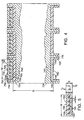
- the flat ropes 722 include a plurality of individual load carrying cords 726 encased within a common layer of coating 728.
- the coating layer 728 separates the individual cords 726 and defines an engagement surface 730 for engaging the traction sheave 724.
- the load carrying cords 726 may be formed from a high-strength, lightweight non-metallic material, such as aramid fibers, or may be formed from a metallic material, such as thin, high-carbon steel fibers. It is desirable to maintain the thickness "d" of the cords 726 as small as possible in order to maximize the flexibility and minimize the stress in the cords 726.
- the fiber diameters should be less than .25 millimeters in diameter and preferably in the range of about .10 millimeters to .20 millimeters in diameter.
- Steel fibers having such diameter improve the flexibility of the cords and the rope.
- the traction sheave diameter "D" may be reduced while maintaining the maximum rope pressure within acceptable limits.
- the engagement surface 730 is in contact with a corresponding surface 750 of the traction sheave 724.
- the coating layer 728 is formed from a polyurethane material, preferably a thermoplastic urethane, that is extruded onto and through the plurality of cords 726 in such a manner that each of the individual cords 726 is restrained against longitudinal movement relative to the other cords 726.
- Other materials may also be used for the coating layer if they are sufficient to meet the required functions of the coating layer: traction, wear, transmission of traction loads to the cords and resistance to environmental factors.
- thermoplastic urethane if they do not meet or exceed the mechanical properties of a thermoplastic urethane, then the benefits resulting from the use of flat ropes may be reduced. With the thermoplastic urethane mechanical properties the traction sheave 724 diameter is reducible to 100 millimeters or less.
- the rope pressure may be distributed more uniformly throughout the rope 722. Because of the incorporation of a plurality of small cords 726 into the flat rope elastomer coating layer 728, the pressure on each cord 726 is significantly diminished over prior art ropes. Cord pressure is decreased at least as n -1 ⁇ 2 , with n being the number of parallel cords in the flat rope, for a given load and wire cross section. Therefore, the maximum rope pressure in the flat rope is significantly reduced as compared to a conventionally roped elevator having a similar load carrying capacity.
- the effective rope diameter 'd' (measured in the bending direction) is reduced for the equivalent load bearing capacity and smaller values for the sheave diameter 'D' may be attained without a reduction in the D/d ratio.
- minimizing the diameter D of the sheave permits the use of less costly, more compact, high speed motors as the drive machine.
- a traction sheave 724 having a traction surface 750 configured to receive the flat rope 722 is also shown in FIG 5.
- the engagement surface 750 is complementarily shaped to provide traction and to guide the engagement between the flat ropes 722 and the sheave 724.
- the traction sheave 724 includes a pair of rims 744 disposed on opposite sides of the sheave 724 and one or more dividers 745 disposed between adjacent flat ropes.
- the traction sheave 724 also includes liners 742 received within the spaces between the rims 744 and dividers 745.
- the liners 742 define the engagement surface 750 such that there are lateral gaps 754 between the sides of the flat ropes 722 and the liners 742.
- a traction sheave without liners may be used.
Claims (5)
- Système d'ascenseur comprenant :une cage d'ascenseur (202) définie par la structure périphérique ;une cabine d'ascenseur (206) et un contrepoids (208) situés dans la cage ; etun moteur d'entraînement (210) comprenant une poulie d'entraînement (212) située au niveau d'une partie inférieure de la cage, le moteur d'entraînement étant couplé à la cabine d'ascenseur et au contrepoids via au moins un câble plat (214) pour déplacer la cabine d'ascenseur vers le haut et vers le bas le long de la cage ; caractérisé en ce que :ledit au moins un câble plat (214) fournissant à la fois la suspension et la traction de la cabine d'ascenseur (206).
- Système d'ascenseur selon la revendication 1, comprenant en outre au moins une poulie d'ascenseur (220, 222) couplée à la cabine d'ascenseur (206), des première et seconde poulies de déflecteur (224, 226) couplées à l'intérieur d'une partie supérieure de la cage (202), et une poulie de contrepoids (228) couplée à une partie supérieure du contrepoids (208), le câble plat (214) ayant des première et seconde extrémités (216, 218) couplées à l'intérieur d'une partie supérieure de la cage (202) et s'étendant vers le bas à partir de sa première extrémité (216) via la au moins une poulie d'ascenseur (220, 222) s'étendant vers le haut et faisant une boucle autour de la première poulie de déflecteur (224), s'étendant vers le bas et faisant une boucle autour de la poulie d'entraînement (212), s'étendant vers le haut et faisant une boucle autour de la seconde poulie de déflecteur (226), s'étendant vers le bas et faisant une boucle autour de la poulie de contrepoids (228) et s'étendant vers le haut et se terminant au niveau de sa seconde extrémité (218).
- Système d'ascenseur selon la revendication 2, dans lequel ladite au moins une poulie d'ascenseur (220, 222) est couplée à la face inférieure de la cabine d'ascenseur (206) et le câble plat (214) surbaisse la cabine d'ascenseur (206).
- Système d'ascenseur selon l'une quelconque des revendications 1 à 3, dans lequel le câble plat (214) est réalisé avec un matériau à fibres non métalliques.
- Système d'ascenseur selon l'une quelconque des revendications 1 à 4 dans lequel le câble plat (214) est réalisé à partir d'uréthane.
Priority Applications (1)
| Application Number | Priority Date | Filing Date | Title |
|---|---|---|---|
| EP07010560.6A EP1911715B1 (fr) | 1998-02-26 | 1999-02-19 | Système élévateur dont le moteur d'entraînement est situé dans la partie inférieure du puits |
Applications Claiming Priority (7)
| Application Number | Priority Date | Filing Date | Title |
|---|---|---|---|
| US09/031,108 US6401871B2 (en) | 1998-02-26 | 1998-02-26 | Tension member for an elevator |
| US31108 | 1998-02-26 | ||
| US162821 | 1998-09-29 | ||
| US09/162,821 US6860367B1 (en) | 1998-09-29 | 1998-09-29 | Elevator system having drive motor located below the elevator car |
| US09/218,990 US6739433B1 (en) | 1998-02-26 | 1998-12-22 | Tension member for an elevator |
| US218990 | 1998-12-22 | ||
| PCT/US1999/003646 WO1999043600A1 (fr) | 1998-02-26 | 1999-02-19 | Systeme d'ascenseur presentant un moteur d'entrainement situe au niveau de la portion inferieure de la cage d'ascenseur |
Related Child Applications (1)
| Application Number | Title | Priority Date | Filing Date |
|---|---|---|---|
| EP07010560.6A Division EP1911715B1 (fr) | 1998-02-26 | 1999-02-19 | Système élévateur dont le moteur d'entraînement est situé dans la partie inférieure du puits |
Publications (2)
| Publication Number | Publication Date |
|---|---|
| EP1097101A1 EP1097101A1 (fr) | 2001-05-09 |
| EP1097101B1 true EP1097101B1 (fr) | 2007-05-30 |
Family
ID=27363789
Family Applications (1)
| Application Number | Title | Priority Date | Filing Date |
|---|---|---|---|
| EP99936068A Expired - Lifetime EP1097101B1 (fr) | 1998-02-26 | 1999-02-19 | Systeme d'ascenseur presentant un moteur d'entrainement situe au niveau de la portion inferieure de la cage d'ascenseur |
Country Status (4)
| Country | Link |
|---|---|
| EP (1) | EP1097101B1 (fr) |
| DE (1) | DE69936206T2 (fr) |
| ES (1) | ES2285850T3 (fr) |
| WO (1) | WO1999043600A1 (fr) |
Cited By (3)
| Publication number | Priority date | Publication date | Assignee | Title |
|---|---|---|---|---|
| US9546076B2 (en) | 2011-09-15 | 2017-01-17 | Kone Corporation | Suspension arrangement and guide shoe arrangement for an elevator |
| US9643817B2 (en) | 2011-05-18 | 2017-05-09 | Kone Corporation | Elevator arrangement |
| US9758346B2 (en) | 2011-06-22 | 2017-09-12 | Kone Corporation | Tensioning arrangement for a traction means of an elevator |
Families Citing this family (10)
| Publication number | Priority date | Publication date | Assignee | Title |
|---|---|---|---|---|
| DE69720044T2 (de) * | 1996-12-30 | 2003-09-11 | Kone Corp | Seileinrichtung für aufzug |
| DE60043599D1 (de) * | 2000-05-22 | 2010-02-04 | Mitsubishi Electric Corp | Aufzugsvorrichtung |
| FR2813874B1 (fr) * | 2000-09-08 | 2003-01-31 | Sodimas | Installation d'ascenseur pourvue de moyens d'entrainement et de moyens de suspension independants |
| ITPD20010237A1 (it) * | 2001-10-10 | 2003-04-10 | Giorgio Paccagnella | Impianto di sollevamento per persone e/o cose |
| GB2395191B (en) * | 2001-11-05 | 2005-10-19 | Otis Elevator Co | Traction sheave elevators |
| CN1248949C (zh) * | 2002-03-06 | 2006-04-05 | 三菱电机株式会社 | 电梯装置 |
| JP2006513113A (ja) * | 2003-01-11 | 2006-04-20 | チョンドゥ チェ | エレベータのロープ張力平衡装置 |
| FI119020B (fi) * | 2003-11-24 | 2008-06-30 | Kone Corp | Hissi ja menetelmä nostoköysistön hallitsemattoman löystymisen ja/tai tasauslaitteen hallitsemattoman liikkeen estämiseksi |
| FI20125078L (fi) | 2012-01-25 | 2013-07-26 | Kone Corp | Hissi |
| ES2627604B1 (es) * | 2016-01-11 | 2018-05-29 | Santiago Amiano Salaverria | Máquina para plataformas de elevación. |
Family Cites Families (10)
| Publication number | Priority date | Publication date | Assignee | Title |
|---|---|---|---|---|
| US1997060A (en) * | 1931-01-28 | 1935-04-09 | Televator Corp | Conveyer |
| DE2333120A1 (de) * | 1973-06-29 | 1975-01-23 | Rudolf Dr Ing Vogel | Treib- und/oder umlenkrollen fuer stahlbaender als traeger von transportmitteln |
| FR2640604B1 (fr) * | 1988-12-15 | 1991-03-08 | Otis Elevator Co | Ascenseur avec machine d'entrainement a adherence embarquee |
| DE9201374U1 (fr) * | 1992-02-05 | 1992-04-02 | C. Haushahn Gmbh & Co, 7000 Stuttgart, De | |
| JPH069178A (ja) * | 1992-04-09 | 1994-01-18 | Werner Hagel | エレベータ |
| FI95689C (fi) * | 1994-06-23 | 1996-03-11 | Kone Oy | Hissikoneisto |
| BR9500779A (pt) * | 1994-03-02 | 1995-10-24 | Inventio Ag | Cabo como meio de suporte para elevadores |
| FI100793B (fi) * | 1995-06-22 | 1998-02-27 | Kone Oy | Vetopyörähissi |
| DE19632850C2 (de) * | 1996-08-14 | 1998-09-10 | Regina Koester | Treibscheibenaufzug ohne Gegengewicht |
| DE69720044T2 (de) * | 1996-12-30 | 2003-09-11 | Kone Corp | Seileinrichtung für aufzug |
-
1999
- 1999-02-19 WO PCT/US1999/003646 patent/WO1999043600A1/fr active IP Right Grant
- 1999-02-19 ES ES99936068T patent/ES2285850T3/es not_active Expired - Lifetime
- 1999-02-19 DE DE69936206T patent/DE69936206T2/de not_active Expired - Lifetime
- 1999-02-19 EP EP99936068A patent/EP1097101B1/fr not_active Expired - Lifetime
Cited By (3)
| Publication number | Priority date | Publication date | Assignee | Title |
|---|---|---|---|---|
| US9643817B2 (en) | 2011-05-18 | 2017-05-09 | Kone Corporation | Elevator arrangement |
| US9758346B2 (en) | 2011-06-22 | 2017-09-12 | Kone Corporation | Tensioning arrangement for a traction means of an elevator |
| US9546076B2 (en) | 2011-09-15 | 2017-01-17 | Kone Corporation | Suspension arrangement and guide shoe arrangement for an elevator |
Also Published As
| Publication number | Publication date |
|---|---|
| DE69936206D1 (de) | 2007-07-12 |
| EP1097101A1 (fr) | 2001-05-09 |
| WO1999043600A1 (fr) | 1999-09-02 |
| DE69936206T2 (de) | 2008-01-31 |
| ES2285850T3 (es) | 2007-11-16 |
Similar Documents
| Publication | Publication Date | Title |
|---|---|---|
| EP1056675B1 (fr) | Systeme d'ascenseur dont le moteur d'entrainement est situe entre la cabine d'ascenseur et la paroi lateral de la cage d'ascenseur | |
| EP1066213B1 (fr) | Systeme ascenseur avec le moteur d'entrainement monté en haut | |
| EP1591403B1 (fr) | Système d'ascenseur par traction à machines multiples | |
| JP4468823B2 (ja) | エレベータおよびエレベータの製造 | |
| US6860367B1 (en) | Elevator system having drive motor located below the elevator car | |
| EP1056676B1 (fr) | Ascenceur a montee sur courroie dote d'un contrepoids a entrainement integre | |
| EP1056679B1 (fr) | Systeme d'ascenseur exempt de local de machinerie, la machinerie etant montee sur la cabine d'ascenseur | |
| CZ20031764A3 (cs) | Bezpřevodovkový lanový výtah s dvojitě opásaným hnacím kolem | |
| EP1042209B1 (fr) | Systeme d'ascenseurs dont le moteur d'entrainement est adjacent a la porte paliere | |
| JP2006505471A (ja) | カウンタウェイトを有さないトラクションシーブエレベータ | |
| EP1097101B1 (fr) | Systeme d'ascenseur presentant un moteur d'entrainement situe au niveau de la portion inferieure de la cage d'ascenseur | |
| EA006912B1 (ru) | Устройство для натяжения каната лифта | |
| SK6912003A3 (en) | Elevator hoist rope thin high-strengh wires | |
| WO1998029326A1 (fr) | Dispositif de cable d'ascenseur | |
| EP1064216A2 (fr) | Ascenseur a levage par cable et a deux poulies a gorges, deplace par deux cables plats souples | |
| US4842101A (en) | Elevator system | |
| EP1911715B1 (fr) | Système élévateur dont le moteur d'entraînement est situé dans la partie inférieure du puits | |
| JP2005529042A (ja) | エレベータ | |
| WO1999043602A1 (fr) | Ascenseur a cable elevateur, presentant un contrepoids d'entrainement et un entrainement ordinaire, ainsi qu'un cable de suspension | |
| EP1676807B1 (fr) | Systeme d'ascenseur avec moteur d'entrainement monté en haut de la gaine | |
| EP1808399B1 (fr) | Ascenseur à câble élévateur doté d'un contrepoids d'entraînement | |
| EP1604938B1 (fr) | Ascenseur avec moteur placé à côté de la porte palière | |
| KR101143330B1 (ko) | 엘리베이터 케이블용 텐션 수단 | |
| US7874404B1 (en) | Elevator system having drive motor located between elevator car and hoistway sidewall | |
| PT1056675E (pt) | Sistema de elevador que tem motor de accionamento localizado entre o carro de elevador e a parede lateral da via de elevação |
Legal Events
| Date | Code | Title | Description |
|---|---|---|---|
| PUAI | Public reference made under article 153(3) epc to a published international application that has entered the european phase |
Free format text: ORIGINAL CODE: 0009012 |
|
| 17P | Request for examination filed |
Effective date: 20000505 |
|
| AK | Designated contracting states |
Kind code of ref document: A1 Designated state(s): DE ES FR IT PT |
|
| 17Q | First examination report despatched |
Effective date: 20031208 |
|
| GRAP | Despatch of communication of intention to grant a patent |
Free format text: ORIGINAL CODE: EPIDOSNIGR1 |
|
| GRAS | Grant fee paid |
Free format text: ORIGINAL CODE: EPIDOSNIGR3 |
|
| GRAA | (expected) grant |
Free format text: ORIGINAL CODE: 0009210 |
|
| AK | Designated contracting states |
Kind code of ref document: B1 Designated state(s): DE ES FR IT PT |
|
| REG | Reference to a national code |
Ref country code: PT Ref legal event code: SC4A Free format text: AVAILABILITY OF NATIONAL TRANSLATION Effective date: 20070606 |
|
| REF | Corresponds to: |
Ref document number: 69936206 Country of ref document: DE Date of ref document: 20070712 Kind code of ref document: P |
|
| ET | Fr: translation filed | ||
| REG | Reference to a national code |
Ref country code: ES Ref legal event code: FG2A Ref document number: 2285850 Country of ref document: ES Kind code of ref document: T3 |
|
| PLBE | No opposition filed within time limit |
Free format text: ORIGINAL CODE: 0009261 |
|
| STAA | Information on the status of an ep patent application or granted ep patent |
Free format text: STATUS: NO OPPOSITION FILED WITHIN TIME LIMIT |
|
| 26N | No opposition filed |
Effective date: 20080303 |
|
| PGFP | Annual fee paid to national office [announced via postgrant information from national office to epo] |
Ref country code: PT Payment date: 20140218 Year of fee payment: 16 |
|
| PGFP | Annual fee paid to national office [announced via postgrant information from national office to epo] |
Ref country code: IT Payment date: 20150217 Year of fee payment: 17 |
|
| REG | Reference to a national code |
Ref country code: PT Ref legal event code: MM4A Free format text: LAPSE DUE TO NON-PAYMENT OF FEES Effective date: 20150819 |
|
| PG25 | Lapsed in a contracting state [announced via postgrant information from national office to epo] |
Ref country code: PT Free format text: LAPSE BECAUSE OF NON-PAYMENT OF DUE FEES Effective date: 20150819 |
|
| REG | Reference to a national code |
Ref country code: FR Ref legal event code: PLFP Year of fee payment: 18 |
|
| PG25 | Lapsed in a contracting state [announced via postgrant information from national office to epo] |
Ref country code: IT Free format text: LAPSE BECAUSE OF NON-PAYMENT OF DUE FEES Effective date: 20160219 |
|
| REG | Reference to a national code |
Ref country code: FR Ref legal event code: PLFP Year of fee payment: 19 |
|
| PGFP | Annual fee paid to national office [announced via postgrant information from national office to epo] |
Ref country code: FR Payment date: 20170124 Year of fee payment: 19 Ref country code: DE Payment date: 20170119 Year of fee payment: 19 |
|
| PGFP | Annual fee paid to national office [announced via postgrant information from national office to epo] |
Ref country code: ES Payment date: 20170123 Year of fee payment: 19 |
|
| REG | Reference to a national code |
Ref country code: DE Ref legal event code: R082 Ref document number: 69936206 Country of ref document: DE Representative=s name: SCHMITT-NILSON SCHRAUD WAIBEL WOHLFROM PATENTA, DE |
|
| REG | Reference to a national code |
Ref country code: DE Ref legal event code: R119 Ref document number: 69936206 Country of ref document: DE |
|
| REG | Reference to a national code |
Ref country code: FR Ref legal event code: ST Effective date: 20181031 |
|
| PG25 | Lapsed in a contracting state [announced via postgrant information from national office to epo] |
Ref country code: DE Free format text: LAPSE BECAUSE OF NON-PAYMENT OF DUE FEES Effective date: 20180901 |
|
| PG25 | Lapsed in a contracting state [announced via postgrant information from national office to epo] |
Ref country code: FR Free format text: LAPSE BECAUSE OF NON-PAYMENT OF DUE FEES Effective date: 20180228 |
|
| REG | Reference to a national code |
Ref country code: ES Ref legal event code: FD2A Effective date: 20190801 |
|
| PG25 | Lapsed in a contracting state [announced via postgrant information from national office to epo] |
Ref country code: ES Free format text: LAPSE BECAUSE OF NON-PAYMENT OF DUE FEES Effective date: 20180220 |