EP0945248A2 - Hochstabile Lamelle, Vulkanisationsform mit solchen Lamellen, Fahrzeugreifen mit Lauffläche, in die Einschnitte mittels solcher Lamellen gebracht sind - Google Patents
Hochstabile Lamelle, Vulkanisationsform mit solchen Lamellen, Fahrzeugreifen mit Lauffläche, in die Einschnitte mittels solcher Lamellen gebracht sind Download PDFInfo
- Publication number
- EP0945248A2 EP0945248A2 EP99103441A EP99103441A EP0945248A2 EP 0945248 A2 EP0945248 A2 EP 0945248A2 EP 99103441 A EP99103441 A EP 99103441A EP 99103441 A EP99103441 A EP 99103441A EP 0945248 A2 EP0945248 A2 EP 0945248A2
- Authority
- EP
- European Patent Office
- Prior art keywords
- dividing lines
- slat
- lines
- depth
- tread
- Prior art date
- Legal status (The legal status is an assumption and is not a legal conclusion. Google has not performed a legal analysis and makes no representation as to the accuracy of the status listed.)
- Granted
Links
- 238000004073 vulcanization Methods 0.000 title claims abstract description 29
- 241000446313 Lamella Species 0.000 claims abstract description 57
- 238000004519 manufacturing process Methods 0.000 claims description 10
- 230000002093 peripheral effect Effects 0.000 claims description 5
- 238000013461 design Methods 0.000 description 8
- 238000005452 bending Methods 0.000 description 7
- 238000005520 cutting process Methods 0.000 description 6
- 238000005299 abrasion Methods 0.000 description 5
- 230000000694 effects Effects 0.000 description 5
- 239000002184 metal Substances 0.000 description 5
- 230000015572 biosynthetic process Effects 0.000 description 4
- 241001136792 Alle Species 0.000 description 3
- 239000010432 diamond Substances 0.000 description 3
- 230000035515 penetration Effects 0.000 description 3
- 238000004873 anchoring Methods 0.000 description 2
- 150000001875 compounds Chemical class 0.000 description 2
- 238000005516 engineering process Methods 0.000 description 2
- 239000000463 material Substances 0.000 description 2
- 230000000149 penetrating effect Effects 0.000 description 2
- 230000000737 periodic effect Effects 0.000 description 2
- 230000006641 stabilisation Effects 0.000 description 2
- 238000011105 stabilization Methods 0.000 description 2
- 241001295925 Gegenes Species 0.000 description 1
- 238000004458 analytical method Methods 0.000 description 1
- 230000005540 biological transmission Effects 0.000 description 1
- 239000012141 concentrate Substances 0.000 description 1
- 238000001816 cooling Methods 0.000 description 1
- 230000007423 decrease Effects 0.000 description 1
- 230000001419 dependent effect Effects 0.000 description 1
- 238000011161 development Methods 0.000 description 1
- 230000018109 developmental process Effects 0.000 description 1
- 238000004049 embossing Methods 0.000 description 1
- ZINJLDJMHCUBIP-UHFFFAOYSA-N ethametsulfuron-methyl Chemical compound CCOC1=NC(NC)=NC(NC(=O)NS(=O)(=O)C=2C(=CC=CC=2)C(=O)OC)=N1 ZINJLDJMHCUBIP-UHFFFAOYSA-N 0.000 description 1
- 230000012447 hatching Effects 0.000 description 1
- 238000005259 measurement Methods 0.000 description 1
- 230000003340 mental effect Effects 0.000 description 1
- 238000000034 method Methods 0.000 description 1
- 238000012986 modification Methods 0.000 description 1
- 230000004048 modification Effects 0.000 description 1
- 239000004033 plastic Substances 0.000 description 1
- 230000001141 propulsive effect Effects 0.000 description 1
- 230000001360 synchronised effect Effects 0.000 description 1
- 238000012549 training Methods 0.000 description 1
- 230000005641 tunneling Effects 0.000 description 1
- 238000009423 ventilation Methods 0.000 description 1
- 238000013022 venting Methods 0.000 description 1
- 239000011800 void material Substances 0.000 description 1
Images


Classifications
-
- B—PERFORMING OPERATIONS; TRANSPORTING
- B60—VEHICLES IN GENERAL
- B60C—VEHICLE TYRES; TYRE INFLATION; TYRE CHANGING; CONNECTING VALVES TO INFLATABLE ELASTIC BODIES IN GENERAL; DEVICES OR ARRANGEMENTS RELATED TO TYRES
- B60C11/00—Tyre tread bands; Tread patterns; Anti-skid inserts
- B60C11/03—Tread patterns
- B60C11/12—Tread patterns characterised by the use of narrow slits or incisions, e.g. sipes
-
- B—PERFORMING OPERATIONS; TRANSPORTING
- B29—WORKING OF PLASTICS; WORKING OF SUBSTANCES IN A PLASTIC STATE IN GENERAL
- B29C—SHAPING OR JOINING OF PLASTICS; SHAPING OF MATERIAL IN A PLASTIC STATE, NOT OTHERWISE PROVIDED FOR; AFTER-TREATMENT OF THE SHAPED PRODUCTS, e.g. REPAIRING
- B29C33/00—Moulds or cores; Details thereof or accessories therefor
- B29C33/30—Mounting, exchanging or centering
- B29C33/301—Modular mould systems [MMS], i.e. moulds built up by stacking mould elements, e.g. plates, blocks, rods
-
- B—PERFORMING OPERATIONS; TRANSPORTING
- B29—WORKING OF PLASTICS; WORKING OF SUBSTANCES IN A PLASTIC STATE IN GENERAL
- B29D—PRODUCING PARTICULAR ARTICLES FROM PLASTICS OR FROM SUBSTANCES IN A PLASTIC STATE
- B29D30/00—Producing pneumatic or solid tyres or parts thereof
- B29D30/06—Pneumatic tyres or parts thereof (e.g. produced by casting, moulding, compression moulding, injection moulding, centrifugal casting)
- B29D30/0601—Vulcanising tyres; Vulcanising presses for tyres
- B29D30/0606—Vulcanising moulds not integral with vulcanising presses
-
- B—PERFORMING OPERATIONS; TRANSPORTING
- B60—VEHICLES IN GENERAL
- B60C—VEHICLE TYRES; TYRE INFLATION; TYRE CHANGING; CONNECTING VALVES TO INFLATABLE ELASTIC BODIES IN GENERAL; DEVICES OR ARRANGEMENTS RELATED TO TYRES
- B60C11/00—Tyre tread bands; Tread patterns; Anti-skid inserts
- B60C11/03—Tread patterns
- B60C11/12—Tread patterns characterised by the use of narrow slits or incisions, e.g. sipes
- B60C11/1204—Tread patterns characterised by the use of narrow slits or incisions, e.g. sipes with special shape of the sipe
- B60C11/1218—Three-dimensional shape with regard to depth and extending direction
-
- B—PERFORMING OPERATIONS; TRANSPORTING
- B60—VEHICLES IN GENERAL
- B60C—VEHICLE TYRES; TYRE INFLATION; TYRE CHANGING; CONNECTING VALVES TO INFLATABLE ELASTIC BODIES IN GENERAL; DEVICES OR ARRANGEMENTS RELATED TO TYRES
- B60C11/00—Tyre tread bands; Tread patterns; Anti-skid inserts
- B60C11/03—Tread patterns
- B60C11/13—Tread patterns characterised by the groove cross-section, e.g. for buttressing or preventing stone-trapping
-
- B—PERFORMING OPERATIONS; TRANSPORTING
- B29—WORKING OF PLASTICS; WORKING OF SUBSTANCES IN A PLASTIC STATE IN GENERAL
- B29D—PRODUCING PARTICULAR ARTICLES FROM PLASTICS OR FROM SUBSTANCES IN A PLASTIC STATE
- B29D30/00—Producing pneumatic or solid tyres or parts thereof
- B29D30/06—Pneumatic tyres or parts thereof (e.g. produced by casting, moulding, compression moulding, injection moulding, centrifugal casting)
- B29D30/0601—Vulcanising tyres; Vulcanising presses for tyres
- B29D30/0606—Vulcanising moulds not integral with vulcanising presses
- B29D2030/0607—Constructional features of the moulds
- B29D2030/0613—Means, e.g. sipes or blade-like elements, for forming narrow recesses in the tyres, e.g. cuts or incisions for winter tyres
-
- B—PERFORMING OPERATIONS; TRANSPORTING
- B29—WORKING OF PLASTICS; WORKING OF SUBSTANCES IN A PLASTIC STATE IN GENERAL
- B29L—INDEXING SCHEME ASSOCIATED WITH SUBCLASS B29C, RELATING TO PARTICULAR ARTICLES
- B29L2030/00—Pneumatic or solid tyres or parts thereof
-
- Y—GENERAL TAGGING OF NEW TECHNOLOGICAL DEVELOPMENTS; GENERAL TAGGING OF CROSS-SECTIONAL TECHNOLOGIES SPANNING OVER SEVERAL SECTIONS OF THE IPC; TECHNICAL SUBJECTS COVERED BY FORMER USPC CROSS-REFERENCE ART COLLECTIONS [XRACs] AND DIGESTS
- Y10—TECHNICAL SUBJECTS COVERED BY FORMER USPC
- Y10S—TECHNICAL SUBJECTS COVERED BY FORMER USPC CROSS-REFERENCE ART COLLECTIONS [XRACs] AND DIGESTS
- Y10S152/00—Resilient tires and wheels
- Y10S152/03—Slits in threads
Definitions
- the lamella according to the invention is in a manner known per se intended for use in a vulcanization mold (2), whereby this vulcanization form (2) for the production of a Vehicle tire (3) is determined.
- Slats according to the invention are in the area of the tread of the manufactured tire arranged in this tread To create incisions whose shape - from the minimal, even shrinkage apart - the negative of Slat shape is.
- a reduced incision depth eliminates this Disadvantages, but creates the other disadvantage that after abrasion a profile depth corresponding to the reduced incision depth no more cuts are available; in order to the tire would lose its grip on mud.
- Usual notch thicknesses for car tires are between 0.4 and 1.0 mm, particularly common for car tires at approx. 0.6 mm.
- Car tires are the preferred application of the invention. Insofar as cuts in van tires, light truck tires or even used for heavy truck tires, their required thickness increases, approximately with the root the intended tire pressure and linear with the Profile depth; for heavy trucks with around 4 times air pressure and double the depth of the profile are therefore feasible incision thicknesses between 1.6 and 4.0 mm, preferably at 2.4 mm.
- the first group includes the suggestions, the wavy ones Teach cuts.
- all surveys are linear highest point - often as “mountain”, more precisely and therefore hereinafter referred to as “Bergkamm (BK)” - and all sinks a line-shaped lowest point, often called a “valley”, here is more precisely referred to as “valley bottom (TS)”.
- BK Bathball
- TS valley bottom
- the generic feature a defines - starting from the usual way of installing the slats so that they produced Incisions in the tire essentially axially and radially run - the measurement direction for the height of the surveys and the depth of the depressions as approximately parallel to the peripheral surface the tread of the manufactured or ultimately vehicle tire to be manufactured.
- the depth of the depressions is called negative amount. So for the bump height and Bulge depth (more precisely: dent depth) the same reference number used: Z.
- the previously known proposal of the second group shows up in the same cut plane, isolated, aligned aligned diamonds, i.e. equilateral quadrilaterals.
- the aligned sides of these diamonds describe exactly two Coulters of parallel, straight, broken lines. Run within each crowd thus the - broken - lines parallel; the lines different crowds cross.
- these dividing lines (T) in be arranged at least two groups, the dividing lines (T) run parallel to each other within each family and the dividing lines (T) of different shares intersect.
- the lamellas are subjected to radial pressure and thus to buckling charged during the profile-generating residual survey of the Tire blanks after closing the mold and before the start of the Vulcanization.
- their Residual elevation is less than the incision depth, the Slats from touching the edges forming the base of the incision with the blank periphery also in the segment boundary areas to radial and circumferential pressure and thus loaded on buckling and bending.
- There is none Degree of freedom from buckling more within the Z 0 reference surface.
- lamellae according to the invention are capable of up to higher radial forces kink-resistant in relation to the slat wall thickness.
- This enables a smaller slat wall thickness with the effect on the tire properties, that at a particularly low level Block bending that limits an incision - especially closely spaced - put walls on each other and so the generate the desired form fit.
- Block bending that limits an incision - especially closely spaced - put walls on each other and so the generate the desired form fit.
- the bars between the truss nodes if possible be kink-resistant in relation to their width and thickness they are preferably not curved, but straight. So it is recommended to choose the preferred curvature on the Focus truss knot.
- the fold lines of the Z 0 reference surface with at least some (more preferred: all) Dividing lines (T) one of the three sets of dividing lines (T) coincide, these more preferably - based on the finished tire - run essentially radially.
- a bend angle of 3 ° from period to period considerable stabilization; Buckling angle above 30 ° appear unnecessary.
- the sheet metal wall thicknesses all refer to the used sheet metal blank.
- the shape and advantages of the triangular framework lamellae according to the invention are particularly evident, if narrow areas around the dividing lines to be addressed as bars or rods, by the formative Bulge remain excluded.
- the width should be (b) the web surfaces (S) between parallel baselines neighboring pyramids should be less than 40% of the edge length of the pyramid base areas, preferably about 20% thereof.
- the latter embodiment of the invention is a mixed form between a pure form according to claim 1 in combination with claim 6 and the other pure form according to claim 2, because it mainly meets claim 2, but on the edge of few inverse oriented extremes (here marked with "+") the combination of claims 1 and 6.
- Mixed forms between claims 1 and 2 are the subject of Claim 7.
- the three intersecting coulters essentially straight Includes dividing lines (T) and thus a gate from about forms equilateral triangles, along at least one of the Bisecting said dividing lines crossing each other outstanding differently oriented bulges in one Orientation sequence that deviates from the alternation + - + - + - + -, preferably according to the short form + --- + ---, whereby as positive bulge surveys and as a negative bulge Sinks or vice versa.
- the axes of whatever periodicity should be chosen be the bisector of the triangular bases.
- each survey (4) should be one slat according to the invention (1) as - apart from possibly.
- Edge rounding or breaking - one on one equilateral triangle as a base, raised Represent pyramid and analog according to claim 4 should be each depression (5) of a lamella (1) according to the invention as - apart from possible edge rounding or breaking - one on an approximately equilateral triangle as the base depict building, deepened pyramid.
- the height of these pyramids is equal to the square root one sixth (approx. 0.4082) times their baseline length is and in accordance with claim 8 (so deviating from claims 9 and 10) the baselines adjacent Bulges coincide, i.e. have a distance of 0, and if according to claim 6 the orientation (raising or lowering) the bulges along the bisector of the Alternate footprints, then the result turns out to be alternately represent cubes placed on top, i.e. as an alternating sequence of interior surfaces and Cube outer surfaces; but is expedient in view towards a sufficiently easy release from the mold manufacturing tires the pyramid height is chosen smaller, particularly preferred at about 30% of the baseline length.
- Such a sense of rotation can be used in particular for rear-wheel drive vehicles Vehicle are used, the rear axle tires are essentially to be interpreted for good propulsion and whose front axle tires essentially have good braking properties are to be interpreted.
- the particularly important periodicity in the short notation + - + - + - + - has the advantage of avoiding a sense of rotation with the shortest possible period length, namely two pitch lengths, which means vice versa that the pitch length can be chosen reasonably large for car tires preferably about 3 mm.
- the pitch lengths are too small supporting surfaces become too small and therefore have less effect stiffening.
- each of the three baselines (B) of a triangular pyramid Elevation (4) with a triangular pyramid-shaped depression (5) each connects to a baseline (B) and that to each of the three baselines (B) of a triangular pyramidal depression (5) a triangular pyramid-shaped elevation (4) with each connects a baseline (B).
- Slats according to the invention are intended in that the Area of the tread pattern defining the cavern Vulcanization mold attached to the manufacture of tires become. According to claim 13 not all slats need Vulcanization forms according to the invention to be designed; rather is a combination with other slat types possible. Be particularly preferred slats according to the invention used in the mold areas that the shoulder positives of the tire ultimately to be manufactured take an impression. Compared to the one for the tread center area, for example recommended slats according to DE 196 50 702 bring incisions according to the invention a particularly high Lateral force transmission, which is best in the shoulder area Validity comes.
- the deviations from mentioned ideal angle of 60 ° less than 5 °.
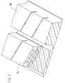
- FIG. 1 shows a perspective view of a vehicle tire 3 according to the invention.
- the section profile of the tread L is rotationally bound due to an arrowing of the transverse grooves 6 that is axially symmetrical with the zenith circumferential line.
- This exemplary profile is divided axially by two wide circumferential grooves 7 and five narrow circumferential grooves 8.
- the entirety of all tread positives is in the form of blocks 9, each of which is delimited laterally by circumferential grooves 7 or 8 and front and rear by a transverse groove 6.
- the entirety of the negatives include the said transverse grooves 6 and circumferential grooves 7 and 8 still incisions 10. At cut through this exemplary design only, two each these incisions 10 each block 9 and parallel to it the transverse grooves 6.
- two each these incisions 10 each block 9 and parallel to it the transverse grooves 6.
- the present invention relates to the incisions 10, however not primarily the one in the top view shown here visible shape of these incisions 10, but their course into the depth of the profile.
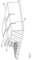
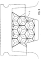
- FIG. 2 shows a perspective view from far above and slightly to the right of an enlarged section of the tread of the tire according to FIG. 1, a block area located on the left having been cut off to provide a view of a flank surface of an incision according to the invention with alternating arrangement of elevations and depressions to expose.
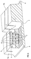
- Figures 3 to 5 show the same detail as Figure 2 on the same scale, but from a different point of view, namely: 3 from less far up and further to the right than FIG. 2, 4 compared to FIG. 3 from even less far above, Figure 5 compared to Figure 2 from less far up and diagonally from the left instead of slightly from the right.
- the coordinate axis z is arranged. Run the x-axis exactly in the axial and the y-axis exactly in the Radials, the z-axis would run exactly in the tire circumferential direction. It is known for noise reasons expedient, the incisions at angles between 5 ° and 40 ° the exact axials to unscrew; the sound-stimulating Incision infeed and incision outflow events occur then not quite as abrupt. That is why they are here too Incisions slightly inclined to the axial.
- the y coordinate here is exactly in the radial of the tire placed. But it should also be in a manner known per se in contrast to be inclined up to about 20 ° to a Non-slip specialization between tunneling or To cause delay.
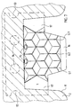
- pitch length t is the distance from nodes to mean nodes along the respective dividing line T, such as shown in Figure 6.
- Pitch length th is the length of the respective bisector meant within a triangular pyramid base. If this pyramid base - as preferred and in all Figures - exactly an equilateral triangle, then it is (th) half the square root of 3 times that Knot pitch (t).
- FIGS. 7 to 13 show - still belonging to embodiment I - the lamella 1, by means of which the incisions 10 in the previous FIGS. 2 to 6 were produced.
- the lamella is shown on a larger scale than the incision in Figures 2 to 6, namely in Figure 7 on a scale of 1: 8.
- the scale and the sheet orientation were chosen so that the A4 format of the drawing sheet was used optimally.
- the semicircular recesses 13 shown increase in resistance to tearing is known. Because the Mold opening resistance due to bulges is high, the arrangement of further penetration holes 14 recommend to safely avoid slat tearing; around the clarity of the other figures does not increase affect such holes 14 but only in Figure 7 shown.
- FIG. 7 shows a top view - corresponding to a view perpendicular to the xy plane, that is to say in the z direction, and thus approximately in the circumferential direction of the tire to be produced - of the lamella 1 according to the invention. It is in a radially inner region 16 and in both axial edge regions 17 smooth, without bulges. In the included area there are bulges of the type according to the invention.
- FIG. 8 shows the same as FIG. 7, but - to make the essence of the invention more apparent - dispenses with all hatching, the penetration bores 14, the reference numerals dealt with so far, but indicates the division lines T with dash-dotted lines.
- FIG. 9 shows the lamella 1 in an end view, specifically here according to a view in the radial direction from the inside to the radially outward against the cavern wall of the vulcanization mold according to the invention.
- the peaks G appear on the drawing sheet above.
- the peaks G1, G2 and G3 are specially marked, the analogy to the top view according to FIG. 7, where the same Summit have the same reference numerals to clarify.
- the crater K can be seen at the bottom of the drawing sheet.
- Figure 10 shows in a front view perpendicular to Figure 9 - corresponding approximately to a view in the axial direction from left to right of the vulcanization mold according to the invention - the same lamella on the same scale as Figures 7 to 9.
- FIG. 11 shows the same lamella in a perspective view close to the viewing angle of FIG. 7, but not exactly in the circumferential direction of the tire to be produced, but slightly from radially inside to radially outside and slightly from left to right.
- FIG. 12 shows the same as FIG. 11, but with the dot-dash lines T.
- FIG. 13 shows the same lamella 1 in a perspective view, but more radially outwards and now looking at a flat angle from right to left. This will put the craters in the shadow of the elevations.
- FIG. 11 in the lamella area in the center of the picture, which characterizes the invention, there is no addition of dividing lines and reference symbols.
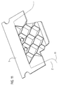
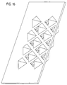
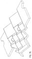
- FIGS. 15 to 17 show the same lamella 1 as FIG. 14, but in perspective from different viewing angles and without specifying the dividing lines T, namely FIG. 15 from a viewing angle slightly from the radially outside and slightly from the left, FIG. 16 from a viewing angle clearly from the radial inside and slightly from the left and Figure 17 from a viewing angle very slightly from the radial inside and slightly from the right.
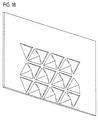
- Figure 18 shows this modified lamella 1 in one Perspective diagonally from the front, Figure 19 from behind, so there all pyramids appear as sinks. Accordingly all triangular trusses according to the invention appear in FIG forming ridges as mountain ridges BK.
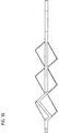
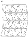
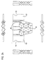
- FIGS. 20 to 25 are dedicated to an exemplary embodiment IV. While maintaining the - not necessary but preferred - feature from Example III, namely that all bulges are oriented identically, here is not an essentially flat but a folded lamella 1, with the strip on the far left in FIG. 20 in a frontal view - according to the view essentially in the circumferential direction in the tire manufactured with it - appears.
- the Z 0 reference surface that contains the dividing lines T (the for the sake of clarity are only shown in FIG. 20) So not exactly, but along the dividing lines of one of the three coulters folded. These folds are used for spatial stabilization of the otherwise essentially only flat, stable framework of the bridges S.
- the so generated Edges should be roughly in the radial direction with these slats vulcanization form to be equipped and the tire to be manufactured.
- the base lines B of the pyramids are here again symmetrical to the respective division line T and limit the Bridges S on the side.
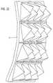
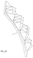
- FIG. 21 shows the same lamella 1 as FIG. 20 from a more radial viewing direction, FIG. 22 from an even more radial viewing direction, FIG. 23 from an even more radial viewing direction than FIG. 22 and somewhat from the left.
- FIG. 25 shows the same lamella 1 as FIGS. 20 to 24, looking here to the rear, so that all bulges appear as depressions.
- the bulges preferably each have the Out the outside of the curve as shown here. In the area of turns, however, where there is hardly any curvature with advantage bulges in both circumferential orientations of the manufacturing tire are arranged, i.e. surveys and Reduce.
Landscapes
- Engineering & Computer Science (AREA)
- Mechanical Engineering (AREA)
- Moulds For Moulding Plastics Or The Like (AREA)
- Heating, Cooling, Or Curing Plastics Or The Like In General (AREA)
- Tires In General (AREA)
- Tyre Moulding (AREA)
Abstract
Description
- eine Lamelle (1) gemäß dem Oberbegriff des Anspruches 1 oder 2,
- gemäß Anspruch 13 auf eine Vulkanisationsform (2) mit Lamellen (1) gemäß dem Oberbegriff von Anspruch 1 oder 2 und
- gemäß Anspruch 14 auf einen Fahrzeugreifen (3) mit einer Lauffläche (L) mit Einschnitten (10) darin, wobei diese Einschnitte (10) mittels Lamellen (1) gemäß dem Oberbegriff des Anspruches 1 oder 2 geformt sind.
- Fig. 1
- in perspektivischer Ansicht einen erfindungsgemäßen Fahrzeugreifen,
- Fig. 2
- in einer perspektivischen Ansicht von weit oben und leicht rechts einen vergrößerten Ausschnitt aus dem Laufstreifen des Reifens gemäß Fig. 1, wobei ein links befindlicher Klotzbereich abgeschnitten wurde, um eine Ansicht auf eine Flankenfläche eines erfindungsgemäßen Einschnittes mit alternierender Anordnung von Erhebungen und Senken frei zu legen,
- Fig. 3
- im gleichen Maßstabe den gleichen Ausschnitt wie Figur 2, jedoch von weniger weit oben und weiter rechts,
- Fig. 4
- im gleichen Maßstabe den gleichen Ausschnitt wie Figur 3, jedoch von noch weniger weit oben,
- Fig. 5
- im gleichen Maßstabe den gleichen Ausschnitt wie Figur 2, jedoch von weniger weit oben und von links,
- Fig. 6
- das Gleiche wie Figur 5, jedoch mit strichpunktierter Angabe der Teilungslinien,
- Fig. 7
- in der Draufsicht - entsprechend etwa einer Sicht in der Umfangsrichtung des herzustellenden Reifens - in einem größeren Maßstabe als die Figuren 2 bis 6 die erfindungsgemäße Lamelle, mittels derer der in den Figuren 2 bis 6 illustrierte Einschnitt erstellt wurde,
- Fig. 8
- das Gleiche wie Figur 7, jedoch mit strichpunktierter Angabe der Teilungslinien,
- Fig. 9
- in einer Stirnansicht - entsprechend etwa einer Sicht in der radialen Richtung von innen her nach radial außen gegen die Kavernenwandung der erfindungsgemäßen Vulkanisationsform - die gleiche Lamelle im gleichen Maßstabe wie die Figuren 7 und 8,
- Fig. 10
- in einer zur Fig. 9 senkrechten Stirnansicht - entsprechend etwa einer Sicht in der axialen Richtung von links nach rechts der erfindungsgemäßen Vulkanisationsform - die gleiche Lamelle im gleichen Maßstabe wie die Figuren 7 bis 9,
- Fig. 11
- die gleiche Lamelle in einer perspektivischen Ansicht nahe dem Blickwinkel der Figur 7, jedoch leicht nach radial außen und leicht nach rechts,
- Fig. 12
- das Gleiche wie Figur 11, jedoch mit strichpunktierter Angabe der Teilungslinien,
- Fig. 13
- ähnlich Figur 11 die gleiche Lamelle in einer perspektivischen Ansicht, jedoch stärker nach radial außen und nunmehr von rechts nach links blickend,
- Fig. 14
- in der Draufsicht - entsprechend einer Blickrichtung etwa in Umfangsrichtung am damit herzustellenden Reifen - eine andere erfindungsgemäße Lamelle mit alternierenden Erhebungen und Senken, bei der zwischen allen benachbarten Ausbeulungen im wesentlichen in der Z=0-Bezugsebene sich erstreckende Stege belassen sind,
- Fig. 15
- die gleiche Lamelle wie in der Figur zuvor, jedoch perspektivisch aus einem Blickwinkel leicht von radial außen und leicht von links,
- Fig. 16
- die gleiche Lamelle wie in der Figur 14, jedoch perspektivisch aus einem Blickwinkel deutlich von radial innen und leicht von links,
- Fig. 17
- die gleiche Lamelle wie in der Figur 14, jedoch perspektivisch aus einem Blickwinkel ganz leicht von radial innen her und leicht von rechts,
- Fig. 18
- in perspektivischer Ansicht eine solche Abwandlung der in den Figuren 14 bis 17 gezeigten Lamelle, dass alle Ausbeulungen gleich herum orientiert sind, in diesem Blickwinkel als Erhebungen erscheinend,
- Fig. 19
- in einer perspektivischen Ansicht von hinten her, also mit invertierter Umfangsrichtungskomponente, die Rückseite der in Figur 18 gezeigten Lamelle, sodass alle Ausbeulungen nun als Senken erscheinen,
- Fig. 20
- eine andere, nämlich gekantete, Lamelle mit Ausbeulungen einer einzigen Orientierung, wobei der Streifen ganz links in frontaler Sicht - entsprechend der Sicht im wesentlichen in Umfangsrichtung im damit gefertigten Reifen - erscheint,
- Fig. 21
- die gleiche Lamelle wie Figur 20 aus einer mehr radialen Blickrichtung,
- Fig. 22
- das Gleiche wie Figur 21, jedoch aus einer noch mehr radialen Blickrichtung,
- Fig. 23
- das Gleiche wie Figur 22, jedoch aus einer noch mehr radialen Blickrichtung und etwas von links,
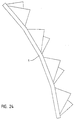
- Fig. 24
- die gleiche Lamelle wie die Figuren 20 bis 23, hier in einer die Z=0-Bezugsfläche tangierenden Blickrichtung, die am fertigen Reifen zumindest in etwa der radialen Blickrichtung entsprechen sollte,
- Fig. 25
- die gleiche Lamelle wie die Figuren 20 bis 24, hier auf die Rückseite schauend, sodass alle Ausbeulungen als Senken erscheinen,
- Fig. 26
- in einem maßstabsgerechten und den ISO-Zeichnungsnormen entsprechenden Übersichtsblatt mit zentraler Vorderansicht (d. h. nach Einbau der Lamelle in eine fertigen Vulkanisationsform in einer Blickrichtung etwa in Umfangsrichtung der Vulkanisationsform) links davon in einer Ansicht von rechts, rechts davon in einer Ansicht von links, darüber in einer Ansicht von unten und darunter in einer Ansicht von oben eine andere, dem Ausführungsbeispiel I (siehe insbesondere die Figuren 7 bis 13) ähnliche Lamelle, wobei jedoch das Muster der Biegelinien um 30° gedreht ist,
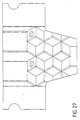
- Fig. 27
- in einem größeren Maßstabe alleine die zentrale Vorderansicht aus Fig. 26,
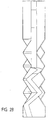
- Fig. 28
- im selben Maßstabe wie Figur 27 alleine die Ansicht von links,
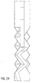
- Fig. 29
- im selben Maßstabe wie Figur 27 alleine die Ansicht von rechts,
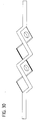
- Fig. 30
- im selben Maßstabe wie Figur 27 alleine die Ansicht von oben,
- Fig. 31
- im selben Maßstabe wie Figur 27 alleine die Ansicht von unten,
- Fig. 32
- im selben Maßstabe wie Figur 27 alleine eine schräge Ansicht im wesentlichen von unten, jedoch auch deutlich von rechts und ganz leicht von vorne,
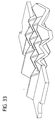
- Fig. 33
- im selben Maßstabe wie Figur 27 alleine eine schräge Ansicht im wesentlichen von unten, jedoch auch deutlich von rechts und ganz leicht von vorne,
- Fig. 34
- im selben Maßstabe wie Figur 27 alleine eine schräge Ansicht im wesentlichen von oben und von links,
- Fig. 35
- im selben Maßstabe wie Figur 27 eine schräge Ansicht ähnlich Figur 32, jedoch weiter von vorne,
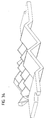
- Fig. 36
- im selben Maßstabe wie Figur 27 eine schräge Ansicht ähnlich Figur 35, jedoch noch weiter von vorne und
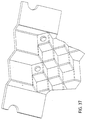
- Fig. 37
- ähnlich wie Figur 27 und im selben Maßstabe eine letzte Ansicht dieser Lamelle, jedoch leicht schräg von links und von oben.
Figur 3 von weniger weit oben und weiter rechts als Figur 2,
Figur 4 gegenüber Figur 3 von noch weniger weit oben,
Figur 5 gegenüber Figur 2 von weniger weit oben und schräg von links statt leicht von rechts.
bei der Erfindung gibt es nur drei Schnittrichtungen, in denen eine solche Achsensymmetrie doch zu beobachten ist, nämlich in den drei Winkelhalbierenden der drei Scharen von Teilungslinien, in diesem Beispiel also die Radiale (siehe Figur 9), die um 120° demgegenüber nach links und die um 120° demgegenüber nach rechts geneigte Achse.
- 1
- Lamelle
- 2
- Vulkanisationsform mit Lamellen 1
- 3
- Fahrzeugreifen, hergestellt in 2
- 4
- Erhebungen in 1
- 5
- Senken in 1
- 6
- Querrillen des Profiles der Lauffläche L des Reifens 3
- 7
- breite Umfangsrillen der Lauffläche L des Reifens 3
- 8
- schmale Umfangsrillen der Lauffläche L des Reifens 3
- 9
- Klötze, als Positive der Lauffläche L des Reifens 3
- 9a
- linker Klotz aus dem in den Figuren 2 bis 6 betrachteten Lauflächenausschnitt
- 9b
- rechter Klotz aus dem in den Figuren 2 bis 6 betrachteten Lauflächenausschnitt
- 10
- Einschnitt in L von 3, hergestellt von 1
- 11
- Peripherie der Kaverne der Vulkanisationsform 2
- 12
- Wurzel der Lamelle 1, mit der sie zwecks Verankerung in 2 hereinragt
- 13
- halbkreisförmige Aussparungen in 12 zur Verstärkung der Verankerung
- 14
- Durchdringungsbohrungen in 12 zur Verstärkung der Verankerung
- 15
- Entlüftungsdurchbrüche am radial äußeren Rande des freien Bereiches von 1
- 16
- glatter radial innerer Bereich von 1
- 17
- glatter axial äußerer Bereich von 1
- b
- Breite der ein Stabfachwerk bildenden Stege S
- t
- Kantenlänge der kleinsten Dreiecke, die durch drei sich kreuzende Teilungslinien T gebildet werden = Abstand von Knotenmittelpunkt zu Knotenmittelpunkt, häufig auch einfach kurz als Teilungslänge bezeichnet
- th
- Länge der Winkelhalbierenden in vorgenannten kleinsten Dreiecken, also von einem Knoten zur Mitte der gegenüberliegenden Seite = kleinste mögliche Teilungslänge der Periodizität in der Abfolge von Erhebungen und Senken (bei ++++++++)
- B
- Basislinie (in den Figuren 2 bis 13 nicht benutzt, weil infolge der Stegbreite 0 praktisch zusammenfallend mit T) einer Pyramide = Schnittlinie zwischen einer Seitenfläche besagter Pyramide und besagter gedachter Grundfläche; dabei ist die Grundfläche vom Gipfel aus gesehen die tiefste bzw. vom Krater aus gesehen die höchste Fläche senkrecht zur Höhe bzw. Tiefe des Gipfels bzw. des Kraters, die ähnlich (also dreieckförmig) ist zu allen darüber bzw. darunter befindlichen parallelen Pyramidenschnittflächen
- BK
- Bergkamm, linienförmige höchste Stelle einer Erhebung 4
- G
- Gipfel (punktförmige höchste Stelle) einer Erhebung 4
- G1
- radial innerer linker Gipfel von 1 in den Figuren 7 und 9
- G2
- radial innerer mittlerer Gipfel von 1 in den Figuren 7 und 9
- G3
- radial innerer rechter Gipfel von 1 in den Figuren 7 und 9
- K
- Krater (punktförmige tiefste Stelle) einer Senke 5
- L
- Lauffläche des Fahrzeugreifens 3
- S
- Stege der Breite b in der Umgebung von T innerhalb der Z=0-Bezugsfläche, gebildet durch Beabstandung der Ausbeulungsränder (=Basislinien B im Falle der bevorzugten pyramidenförmigen Ausbeulungen) voneinander
- T
- Teilungslinie
- TS
- Talsohle, linienförmige tiefste Stelle in Senken 5
- Z4
- Höhe der Erhebungen 4, zu messen etwa parallel zur Peripheriefläche P der Lauffläche L
- Z5
- Tiefe der Senken 5, zu messen etwa parallel zur Peripheriefläche P der Lauffläche L
- Zg
- Höhe der Gipfel G
- Zk
- Tiefe der Krater K
- Zt
- Höhe der Teilungslinien T, zur Definition der Z=0-Bezugsfläche zu Null gesetzt
Claims (14)
- Lamelle (1) zum Einsatz in eine Vulkanisationsform (2) zur Herstellung eines Fahrzeugreifens (3)a) mit Erhebungen (4) und Senken (5), wobei die Höhe (Z4) der Erhebungen (4) und die Tiefe (Z5) der Senken (5) etwa parallel zur Peripheriefläche (P) der Lauffläche (L) des letztlich herzustellenden Fahrzeugreifens (3) weisen,b) wobei jeder Erhebung (4) eine punktförmige höchste Stelle - nachfolgend "Gipfel (G)" genannt - zugeordnet ist, undc) wobei jeder Senke (5) eine punktförmige tiefste Stelle - nachfolgend "Krater (K)" genannt - zugeordnet ist,f) wobei die Erhebungen (4) und die Senken (5) in einer im wesentlichen gleichmäßigen, flächigen Teilung vorliegen,g) wobei besagte flächige Teilung durch im wesentlichen gerade Teilungslinien (T) beschrieben ist, deren Höhe/Tiefe (Zt) - vorzugsweise mittig - zwischen der Höhe (Zg) der Gipfel (G) und der Tiefe (Zk) der Krater (K) liegt,h) wobei diese Teilungslinien (T) in zwei Scharen geordnet sind, wobei die Teilungslinien (T) innerhalb einer jeden Schar parallel zueinander verlaufen und sich die Teilungslinien (L) verschiedener Scharen kreuzen,
dadurch gekennzeichnet,i) dass diese Teilungslinien (T) nicht nur in zwei sondern in drei Scharen geordnet sind,j) wobei sich die Teilungslinien (T) verschiedener Scharen unter einem Winkel von etwa 60° kreuzenk) und so ein Gatter aus - etwa gleichseitigen - Dreiecken bilden. - Lamelle (1) zum Einsatz in eine Vulkanisationsform (2) zur Herstellung eines Fahrzeugreifens (3)a) mit Erhebungen (4) und Senken (5), wobei die Höhe (Z4) der Erhebungen (4) und die Tiefe (Z5) der Senken (5) etwa parallel zur Peripheriefläche (P) der Lauffläche (L) des letztlich herzustellenden Fahrzeugreifens (3) weisen,
wobei entwederb) jede Erhebung (4) eine linienförmige höchste Stelle - nachfolgend "Bergkamm (BK)" genannt - hat, undc) jeder Senke (5) eine punktförmige tiefste Stelle - nachfolgend "Krater (K)" genannt - zugeordnet ist,
oder umgekehrt (je nach Blickorientierung)d) jeder Erhebung (4) eine punktförmige höchste Stelle - nachfolgend "Gipfel (G)" genannt - zugeordnet ist, unde) jede Senke (5) eine linienförmige tiefste Stelle - nachfolgend "Tal" oder "Schlucht (S)" genannt - hat,f) wobei die Erhebungen (4) und die Senken (5) in einer im wesentlichen gleichmäßigen, flächigen Teilung vorliegen,g) wobei besagte flächige Teilung durch im wesentlichen gerade Teilungslinien (T) beschrieben ist, deren Höhe/Tiefe (Zt) auf der Höhe (Zbk oder Zts) der linienförmigen Extreme [Bergkämme (BK) bzw. Talsohlen (TS)] liegt,h) wobei diese Teilungslinien (T) in zwei Scharen geordnet sind, wobei die Teilungslinien (T) innerhalb einer jeden Schar parallel zueinander verlaufen und sich die Teilungslinien (L) verschiedener Scharen kreuzen,
dadurch gekennzeichnet,i) dass diese Teilungslinien (T) nicht nur in zwei sondern in drei Scharen geordnet sind,j) wobei sich die Teilungslinien (T) verschiedener Scharen unter einem Winkel von etwa 60° kreuzenk) und so ein Gatter aus - etwa gleichseitigen - Dreiecken bilden. - Lamelle (1) nach Anspruch 1 oder 2, dadurch gekennzeichnet, dass - abgesehen von evt. Kantenverrundungen oder -brechungen - jede Erhebung (4) sich als eine auf einem etwa gleichseitigen Dreieck als Grundfläche aufbauende erhabene Pyramide darstellt.
- Lamelle (1) nach Anspruch 1 oder 2, dadurch gekennzeichnet, dass - abgesehen von evt. Kantenverrundungen oder -brechungen - jede Senke (5) sich als eine auf einem etwa gleichseitigen Dreieck als Grundfläche aufbauende vertiefte Pyramide darstellt.
- Lamelle (1) nach Anspruch 1, 3 und 4, wobei die Schnittlinie zwischen einer Seitenfläche besagter Pyramide und besagter Grundfläche als "Basislinie (B)" bezeichnet wird, dadurch gekennzeichnet, dass alle drei Basislinien (B) aller Pyramiden mittig zwischen der Höhe (Zg) der Gipfel (G) und der Tiefe (Zk) der Krater (K) liegen.
- Lamelle (1) nach Anspruch 1, 3 und 4, dadurch gekennzeichnet, dass parallel zu jeder der drei Basislinien (B) einer dreiecks-pyramidenförmigen Erhebung (4) eine Basislinie (B) einer dreiecks-pyramidenförmigen Senke (5) anschließt und, dass parallel zu jeder der drei Basislinien (B) einer dreiecks-pyramidenförmigen Senke (5) eine Basislinie (B) einer dreiecks-pyramidenförmigen Erhebung (4) anschließt.
- Lamelle (1), dadurch gekennzeichnet, dass sie (1) bereichsweise gemäß der Kombination aus den Merkmalen der Ansprüche 1 und 6 Ausbeulungen zeigt und in den übrigen Bereichen Ausbeulungen gemäß Anspruch 2 zeigt, wobei als eine positive Ausbeulung (Kurzform: +) eine Erhebung (4) und als negative Ausbeulung (Kurzform: "-") eine Senke (5) aufgefasst wird oder umgekehrt, dadurch weiter gekennzeichnet, dass sie (1) aus einer Z=0-Bezugsfläche - die die drei sich gleichmäßig kreuzenden Scharen im wesentlichen gerader Teilungslinien (T) enthält und damit ein Gatter aus etwa gleichseitigen Dreiecken bildet - entlang zumindest einer der Winkelhalbierenden besagter sich kreuzender Teilungslinien (T) herausragende verschieden orientierte Ausbeulungen enthält in einer Orientierungsabfolge die von der Alternierung +-+-+-+- abweicht, bevorzugt gemäß der Kurzform +---+---.
- Lamelle (1) nach Anspruch 6 oder 7, dadurch gekennzeichnet, dass die zueinander parallelen Basislinien (B) aneinander anschließender Pyramiden den Abstand 0 voneinander haben, also zusammenfallen, sodass sie nicht als Körperkanten erscheinen, infolgedessen sie auch mit den Teilungslinien (T) zusammenfallen.
- Lamelle (1) nach Anspruch 6 oder 7, dadurch gekennzeichnet, dass die zueinander parallelen Basislinien (B) aneinander anschließender Pyramiden einen Abstand größer 0 voneinander haben, sodass sie als - ggf. verrundete oder gebrochene - Körperkanten erscheinen, wobei die Breite b der Stegflächen S zwischen parallelen Basislinien benachbarter Pyramiden kleiner ist als 40 % der Kantenlänge der Pyramiden-Grundflächen, vorzugsweise ca. 20 % davon.
- Lamelle (1) nach Anspruch 9, dadurch gekennzeichnet, dass die Breite b der Stegflächen S zwischen parallelen benachbarten Basislinien höchstens das Doppelte der Stegdicke beträgt.
- Lamelle (1) nach Anspruch 1 oder 2, dadurch gekennzeichnet, dass die Z=0-Bezugsfläche nicht eben, sondern zylindermantelartig oder weiter bevorzugt polygonprismenartig gewölbt oder in einer alternierenden Abfolge solcher Wölbungen gewellt ist.
- Lamelle (1) nach Anspruch 11 mit einer unstetigen, also polygonprismenartigen Wölbung, dadurch gekennzeichnet, dass die Knicklinien der Z=0-Bezugsfläche mit zumindest einigen Teilungslinien (T) einer der drei Scharen von Teilungslinien (T) zusammenfallen, wobei diese weiter bevorzugt - bezogen auf den fertigen Reifen - im wesentlichen radial verlaufen.
- Vulkanisationsform (2) zur Herstellung von Reifen (3), wobei die Form (2) Lamellen (1) aufweist zur Herstellung von Einschnitten (10) in der Lauffläche (L),
dadurch gekennzeichnet, dass zumindest einige der Lamellen als Lamellen (1) gemäß Anspruch 1 oder 2 ausgebildet sind, vorzugsweise gemäß zumindest einem der weiteren Ansprüche 3 bis 12. - Fahrzeugreifen (3) mit einer Lauffläche (L) mit Einschnitten (10),
dadurch gekennzeichnet, dass zumindest einige der Einschnitte (10) mittels Lamellen (1) gemäß Anspruch 1 oder 2 geformt sind, vorzugsweise gemäß zumindest einem der weiteren Ansprüche 3 bis 12.
Applications Claiming Priority (2)
| Application Number | Priority Date | Filing Date | Title |
|---|---|---|---|
| DE19812778 | 1998-03-24 | ||
| DE19812778A DE19812778C2 (de) | 1998-03-24 | 1998-03-24 | Hochstabile Lamelle, Vulkanisationsform mit solchen Lamellen, Fahrzeugreifen mit Lauffläche, in die Einschnitte mittels solcher Lamellen gebracht sind |
Publications (3)
| Publication Number | Publication Date |
|---|---|
| EP0945248A2 true EP0945248A2 (de) | 1999-09-29 |
| EP0945248A3 EP0945248A3 (de) | 2001-01-10 |
| EP0945248B1 EP0945248B1 (de) | 2002-11-20 |
Family
ID=7862036
Family Applications (1)
| Application Number | Title | Priority Date | Filing Date |
|---|---|---|---|
| EP99103441A Expired - Lifetime EP0945248B1 (de) | 1998-03-24 | 1999-02-23 | Hochstabile Lamelle, Vulkanisationsform mit solchen Lamellen, Fahrzeugreifen mit Lauffläche, in die Einschnitte mittels solcher Lamellen gebracht sind |
Country Status (6)
| Country | Link |
|---|---|
| US (1) | US6564840B2 (de) |
| EP (1) | EP0945248B1 (de) |
| JP (1) | JP5059253B2 (de) |
| AT (1) | ATE228060T1 (de) |
| CA (1) | CA2266741A1 (de) |
| DE (2) | DE19812778C2 (de) |
Cited By (5)
| Publication number | Priority date | Publication date | Assignee | Title |
|---|---|---|---|---|
| FR2804905A1 (fr) * | 2000-02-16 | 2001-08-17 | Michelin Soc Tech | Bande de roulement de pneumatique et moule |
| NL2000322C2 (nl) * | 2006-11-20 | 2008-05-21 | Vredestein Banden B V | Loopvlak van een rubberband. |
| EP2006124A1 (de) * | 2007-06-21 | 2008-12-24 | Continental Aktiengesellschaft | Fahrzeugluftreifen mit dreidimensionalen Einschnitten |
| DE102010000272A1 (de) | 2010-02-01 | 2011-08-04 | Continental Reifen Deutschland GmbH, 30165 | Fahrzeugluftreifen |
| EP2058145A4 (de) * | 2006-08-30 | 2011-08-24 | Bridgestone Corp | Luftreifen |
Families Citing this family (38)
| Publication number | Priority date | Publication date | Assignee | Title |
|---|---|---|---|---|
| JP3656731B2 (ja) * | 2000-08-24 | 2005-06-08 | 横浜ゴム株式会社 | 空気入りタイヤ |
| JP4743956B2 (ja) * | 2000-12-20 | 2011-08-10 | 東洋ゴム工業株式会社 | 空気入りタイヤ |
| JP3894743B2 (ja) * | 2001-04-05 | 2007-03-22 | 横浜ゴム株式会社 | 空気入りタイヤ |
| JP2002356105A (ja) * | 2001-05-31 | 2002-12-10 | Toyo Tire & Rubber Co Ltd | 空気入りタイヤ |
| FR2826911A1 (fr) * | 2001-07-09 | 2003-01-10 | Michelin Soc Tech | Bande de roulement pourvue d'incisions |
| JP3648179B2 (ja) * | 2001-07-18 | 2005-05-18 | 住友ゴム工業株式会社 | 空気入りタイヤ及びその加硫金型 |
| FR2829970B1 (fr) * | 2001-09-27 | 2004-05-14 | Michelin Soc Tech | Bande de roulement pour pneumatique |
| JP2004203128A (ja) * | 2002-12-24 | 2004-07-22 | Sumitomo Rubber Ind Ltd | 空気入りタイヤ、及びその製造方法 |
| US7637295B2 (en) | 2003-09-29 | 2009-12-29 | The Yokohama Rubber Co., Ltd. | Pneumatic tire with tread including sipes having bent portions formed with zigzag shape with amplitude in radial direction |
| US7143799B2 (en) | 2003-11-20 | 2006-12-05 | The Goodyear Tire & Rubber Company | Three-dimensional sipes for treads |
| JP4330455B2 (ja) * | 2004-01-09 | 2009-09-16 | 住友ゴム工業株式会社 | 空気入りタイヤ |
| JP4281917B2 (ja) * | 2004-07-21 | 2009-06-17 | 東洋ゴム工業株式会社 | 空気入りタイヤ |
| CN101022965B (zh) * | 2004-08-06 | 2010-05-26 | 株式会社普利司通 | 充气轮胎及其制造方法 |
| US7467652B2 (en) * | 2004-08-06 | 2008-12-23 | The Goodyear Tire & Rubber Company | Three-dimensional tread sipes and mold blade for forming three-dimensional tread sipes |
| JP2006069440A (ja) * | 2004-09-03 | 2006-03-16 | Bridgestone Corp | 空気入りタイヤ |
| JP4561313B2 (ja) * | 2004-10-27 | 2010-10-13 | 横浜ゴム株式会社 | 空気入りタイヤ |
| US7468153B2 (en) | 2004-12-30 | 2008-12-23 | The Goodyear Tire & Rubber Co. | Degradable blading for tire curing molds |
| US7793692B2 (en) * | 2005-10-31 | 2010-09-14 | The Goodyear Tire & Rubber Company | Pneumatic tire tread having sipe that devolves into groove as tread wears |
| ITTO20060143A1 (it) * | 2006-02-28 | 2007-09-01 | Bridgestone Corp | Pneumatico |
| US20070272337A1 (en) * | 2006-05-25 | 2007-11-29 | Lorie Jean Bovaird | Pneumatic tire with tread siping |
| SK882006A3 (sk) * | 2006-06-13 | 2008-01-07 | Matador Rubber, S. R. O. | Pneumatikový behúň a lamela vhodná na upevnenie do vulkanizačnej formy na vytvorenie lamelového zárezu v bloku pneumatikového behúňa |
| JP4211944B2 (ja) * | 2006-11-17 | 2009-01-21 | 東洋ゴム工業株式会社 | 空気入りタイヤ |
| US20090000713A1 (en) * | 2007-06-27 | 2009-01-01 | Bridgestone Firestone North American Tire, Llc | Tire including segmented sipes |
| JP5052317B2 (ja) * | 2007-12-10 | 2012-10-17 | 株式会社ブリヂストン | 空気入りタイヤ |
| JP4438881B2 (ja) * | 2008-04-15 | 2010-03-24 | 横浜ゴム株式会社 | 空気入りタイヤ及びその製造方法、並びに、タイヤ加硫モールド |
| RU2577422C2 (ru) * | 2011-11-04 | 2016-03-20 | Бриджстоун Корпорейшн | Пневматическая шина |
| FR3000424B1 (fr) * | 2012-12-28 | 2015-05-15 | Michelin & Cie | Element de moule comportant des moyens de decoupe pour le moulage et la vulcanisation d'une bande de roulement d'un pneumatique |
| FR3012767B1 (fr) * | 2013-11-05 | 2015-10-23 | Michelin & Cie | Bande de roulement comportant un bloc presentant une pluralite d'incisions |
| AU357504S (en) * | 2014-02-20 | 2014-09-19 | Continental Reifen Deutschland Gmbh | Tyre |
| KR20150138435A (ko) * | 2014-05-07 | 2015-12-10 | 한국타이어 주식회사 | 차량용 공기입 타이어 |
| FR3022493B1 (fr) * | 2014-06-24 | 2016-07-01 | Michelin & Cie | Bande de roulement incisee pour pneu genie civil |
| JP6609214B2 (ja) * | 2016-04-06 | 2019-11-20 | 株式会社ブリヂストン | タイヤモールド及びタイヤ |
| JP7013878B2 (ja) * | 2018-01-11 | 2022-02-01 | 横浜ゴム株式会社 | 空気入りタイヤ |
| JP6844590B2 (ja) * | 2018-07-09 | 2021-03-17 | 横浜ゴム株式会社 | 空気入りタイヤ |
| DE102019217819A1 (de) * | 2019-11-19 | 2021-05-20 | Continental Reifen Deutschland Gmbh | Fahrzeugluftreifen |
| US20240399796A1 (en) | 2021-10-05 | 2024-12-05 | Bridgestone Americas Tire Operations, Llc | Three-dimensional tire sipe |
| JP7803687B2 (ja) * | 2021-11-02 | 2026-01-21 | 株式会社ブリヂストン | タイヤ成形用金型の設計方法、タイヤ成形用金型及びタイヤ成形用金型の製造方法 |
| KR102741186B1 (ko) * | 2022-09-30 | 2024-12-10 | 한국타이어앤테크놀로지 주식회사 | 구간별로 가변 두께를 가진 수직방향 직사각형 커프를 구비한 타이어 |
Family Cites Families (18)
| Publication number | Priority date | Publication date | Assignee | Title |
|---|---|---|---|---|
| FR791250A (fr) | 1935-06-13 | 1935-12-06 | Michelin & Cie | Perfectionnement à la surface de roulement des pneumatiques |
| US3199567A (en) * | 1963-12-30 | 1965-08-10 | Goodrich Co B F | Tire tread |
| DE1480986A1 (de) * | 1965-09-07 | 1970-01-08 | Dunlop Ag | Laufstreifen fuer Fahrzeugreifen |
| US3608602A (en) * | 1968-12-03 | 1971-09-28 | Uniroyal Inc | Stone rejecting tire tread and mold insert therefor |
| DE3324649A1 (de) * | 1983-07-08 | 1985-01-31 | Continental Gummi-Werke Ag, 3000 Hannover | Fahrzeugluftreifen |
| AT398732B (de) * | 1990-03-20 | 1995-01-25 | Semperit Ag | Fahrzeugluftreifen |
| AT401160B (de) * | 1991-05-21 | 1996-07-25 | Semperit Ag | Luftreifen mit einer lauffläche |
| JP3180160B2 (ja) * | 1991-08-27 | 2001-06-25 | 横浜ゴム株式会社 | スタッドレスタイヤ |
| AT400694B (de) * | 1992-04-03 | 1996-02-26 | Semperit Ag | Fahrzeugreifen |
| JPH06143941A (ja) * | 1992-11-05 | 1994-05-24 | Yokohama Rubber Co Ltd:The | 空気入りタイヤ |
| FR2722144B1 (fr) * | 1994-07-05 | 1996-09-27 | Michelin & Cie | Bande de roulement pour pneumatique |
| DE4427895A1 (de) | 1994-08-08 | 1996-02-15 | Continental Ag | Fahrzeugreifen mit einer Lauffläche mit im wesentlichen axial verlaufenden Einschnitten |
| EP0810104A1 (de) * | 1996-05-28 | 1997-12-03 | The Goodyear Tire & Rubber Company | Reifenlauffläche mit Feineinschnitten in den elastomerischen Profilblöcken |
| EP0820885A3 (de) * | 1996-07-24 | 1998-07-08 | Bridgestone Corporation | Luftreifen |
| JP3607011B2 (ja) * | 1996-08-12 | 2005-01-05 | 株式会社ブリヂストン | タイヤ加硫用金型及び空気入りタイヤ |
| DE19650702A1 (de) | 1996-12-06 | 1998-06-10 | Continental Ag | Fahrzeugreifen mit einer Lauffläche mit im wesentlichen axial verlaufenden Einschnitten |
| DE19710400C2 (de) | 1997-03-13 | 2003-05-15 | Continental Ag | Fahrzeugreifen mit Einschnitten im Laufstreifen und Lamelle für Vulkanisationsform und Vulkanisationsform mit solchen Lamellen |
| WO1999048707A1 (en) * | 1998-03-25 | 1999-09-30 | The Goodyear Tire & Rubber Company | Tire tread and mold for making treads |
-
1998
- 1998-03-24 DE DE19812778A patent/DE19812778C2/de not_active Expired - Lifetime
-
1999
- 1999-02-23 AT AT99103441T patent/ATE228060T1/de not_active IP Right Cessation
- 1999-02-23 DE DE59903440T patent/DE59903440D1/de not_active Expired - Lifetime
- 1999-02-23 EP EP99103441A patent/EP0945248B1/de not_active Expired - Lifetime
- 1999-03-23 CA CA002266741A patent/CA2266741A1/en not_active Abandoned
- 1999-03-23 JP JP07845599A patent/JP5059253B2/ja not_active Expired - Lifetime
- 1999-03-24 US US09/324,584 patent/US6564840B2/en not_active Expired - Lifetime
Cited By (7)
| Publication number | Priority date | Publication date | Assignee | Title |
|---|---|---|---|---|
| FR2804905A1 (fr) * | 2000-02-16 | 2001-08-17 | Michelin Soc Tech | Bande de roulement de pneumatique et moule |
| WO2001060642A1 (fr) * | 2000-02-16 | 2001-08-23 | Societe De Technologie Michelin | Bande de roulement de pneumatique |
| EP2058145A4 (de) * | 2006-08-30 | 2011-08-24 | Bridgestone Corp | Luftreifen |
| NL2000322C2 (nl) * | 2006-11-20 | 2008-05-21 | Vredestein Banden B V | Loopvlak van een rubberband. |
| EP2006124A1 (de) * | 2007-06-21 | 2008-12-24 | Continental Aktiengesellschaft | Fahrzeugluftreifen mit dreidimensionalen Einschnitten |
| DE102010000272A1 (de) | 2010-02-01 | 2011-08-04 | Continental Reifen Deutschland GmbH, 30165 | Fahrzeugluftreifen |
| WO2011091870A1 (de) | 2010-02-01 | 2011-08-04 | Continental Reifen Deutschland Gmbh | Fahrzeugluftreifen |
Also Published As
| Publication number | Publication date |
|---|---|
| JP5059253B2 (ja) | 2012-10-24 |
| ATE228060T1 (de) | 2002-12-15 |
| US20020053383A1 (en) | 2002-05-09 |
| DE19812778C2 (de) | 2002-07-04 |
| EP0945248A3 (de) | 2001-01-10 |
| EP0945248B1 (de) | 2002-11-20 |
| DE59903440D1 (de) | 2003-01-02 |
| JPH11310012A (ja) | 1999-11-09 |
| CA2266741A1 (en) | 1999-09-24 |
| US6564840B2 (en) | 2003-05-20 |
| DE19812778A1 (de) | 1999-09-30 |
Similar Documents
| Publication | Publication Date | Title |
|---|---|---|
| EP0945248B1 (de) | Hochstabile Lamelle, Vulkanisationsform mit solchen Lamellen, Fahrzeugreifen mit Lauffläche, in die Einschnitte mittels solcher Lamellen gebracht sind | |
| AT401160B (de) | Luftreifen mit einer lauffläche | |
| DE69505979T2 (de) | Reifenlauffläche | |
| DE602004011728T2 (de) | Dreidimensionale Feineinschnitte für Laufflächen | |
| DE60108972T2 (de) | Reifenlauffläche und formelement eines formwerkzeugs für eine solche lauffläche | |
| DE102010005840B4 (de) | Luftreifen | |
| EP2920007B1 (de) | Fahrzeugluftreifen | |
| DE60219997T2 (de) | Luftreifen | |
| DE60209758T2 (de) | Insbesondere für schneebedeckten boden geeigneter reifen | |
| DE60213098T2 (de) | Mit schlitzen versehene lauffläche | |
| DE60022854T2 (de) | Reifenlauffläche mit unebenen nutenwänden | |
| DE2951444A1 (de) | Fahrzeugreifen | |
| EP1926609B1 (de) | Fahrzeugluftreifen mit mikroeinschnitten | |
| DE102008039069A1 (de) | Luftreifen | |
| DE102018119911B4 (de) | Luftreifen | |
| DE60200758T2 (de) | Laufrichtungsgebundenes laufflächenprofil für einen winterreifen | |
| EP1223054A1 (de) | Reifenlauffläche mit 3-D Lamellen | |
| DE60126392T2 (de) | Reifenlauffläche für Lastkraftwagen | |
| DE102019131570B4 (de) | Luftreifen | |
| DE102008030810A1 (de) | Fahrzeugluftreifen | |
| DE2912608C2 (de) | ||
| EP0864448B1 (de) | Fahrzeugreifen mit Einschnitten im Laufstreifen und Lamelle für Vulkanisationsform und Vulkanisationsform mit solchen Lamellen | |
| EP1106393A2 (de) | Fahrzeugluftreifen | |
| AT404341B (de) | Fahrzeugluftreifen | |
| DE60213445T2 (de) | Reifenlauffläche |
Legal Events
| Date | Code | Title | Description |
|---|---|---|---|
| PUAI | Public reference made under article 153(3) epc to a published international application that has entered the european phase |
Free format text: ORIGINAL CODE: 0009012 |
|
| AK | Designated contracting states |
Kind code of ref document: A2 Designated state(s): AT BE CH CY DE DK ES FI FR GB GR IE IT LI LU MC NL PT SE |
|
| AX | Request for extension of the european patent |
Free format text: AL;LT;LV;MK;RO;SI |
|
| PUAL | Search report despatched |
Free format text: ORIGINAL CODE: 0009013 |
|
| AK | Designated contracting states |
Kind code of ref document: A3 Designated state(s): AT BE CH CY DE DK ES FI FR GB GR IE IT LI LU MC NL PT SE |
|
| AX | Request for extension of the european patent |
Free format text: AL;LT;LV;MK;RO;SI |
|
| 17P | Request for examination filed |
Effective date: 20010710 |
|
| AKX | Designation fees paid |
Free format text: AT CH DE FI FR GB IT LI SE |
|
| 17Q | First examination report despatched |
Effective date: 20020131 |
|
| GRAG | Despatch of communication of intention to grant |
Free format text: ORIGINAL CODE: EPIDOS AGRA |
|
| GRAG | Despatch of communication of intention to grant |
Free format text: ORIGINAL CODE: EPIDOS AGRA |
|
| GRAH | Despatch of communication of intention to grant a patent |
Free format text: ORIGINAL CODE: EPIDOS IGRA |
|
| GRAH | Despatch of communication of intention to grant a patent |
Free format text: ORIGINAL CODE: EPIDOS IGRA |
|
| GRAA | (expected) grant |
Free format text: ORIGINAL CODE: 0009210 |
|
| AK | Designated contracting states |
Kind code of ref document: B1 Designated state(s): AT CH DE FI FR GB IT LI SE |
|
| REF | Corresponds to: |
Ref document number: 228060 Country of ref document: AT Date of ref document: 20021215 Kind code of ref document: T |
|
| REG | Reference to a national code |
Ref country code: GB Ref legal event code: FG4D Free format text: NOT ENGLISH |
|
| REG | Reference to a national code |
Ref country code: CH Ref legal event code: EP |
|
| REF | Corresponds to: |
Ref document number: 59903440 Country of ref document: DE Date of ref document: 20030102 |
|
| REG | Reference to a national code |
Ref country code: CH Ref legal event code: NV Representative=s name: BOVARD AG PATENTANWAELTE |
|
| GBT | Gb: translation of ep patent filed (gb section 77(6)(a)/1977) |
Effective date: 20030318 |
|
| ET | Fr: translation filed | ||
| PLBE | No opposition filed within time limit |
Free format text: ORIGINAL CODE: 0009261 |
|
| STAA | Information on the status of an ep patent application or granted ep patent |
Free format text: STATUS: NO OPPOSITION FILED WITHIN TIME LIMIT |
|
| 26N | No opposition filed |
Effective date: 20030821 |
|
| PGFP | Annual fee paid to national office [announced via postgrant information from national office to epo] |
Ref country code: FR Payment date: 20050210 Year of fee payment: 7 |
|
| PGFP | Annual fee paid to national office [announced via postgrant information from national office to epo] |
Ref country code: AT Payment date: 20050211 Year of fee payment: 7 |
|
| PGFP | Annual fee paid to national office [announced via postgrant information from national office to epo] |
Ref country code: GB Payment date: 20050214 Year of fee payment: 7 |
|
| PGFP | Annual fee paid to national office [announced via postgrant information from national office to epo] |
Ref country code: CH Payment date: 20050216 Year of fee payment: 7 |
|
| PG25 | Lapsed in a contracting state [announced via postgrant information from national office to epo] |
Ref country code: GB Free format text: LAPSE BECAUSE OF NON-PAYMENT OF DUE FEES Effective date: 20060223 Ref country code: AT Free format text: LAPSE BECAUSE OF NON-PAYMENT OF DUE FEES Effective date: 20060223 |
|
| PG25 | Lapsed in a contracting state [announced via postgrant information from national office to epo] |
Ref country code: LI Free format text: LAPSE BECAUSE OF NON-PAYMENT OF DUE FEES Effective date: 20060228 Ref country code: CH Free format text: LAPSE BECAUSE OF NON-PAYMENT OF DUE FEES Effective date: 20060228 |
|
| PGFP | Annual fee paid to national office [announced via postgrant information from national office to epo] |
Ref country code: IT Payment date: 20060228 Year of fee payment: 8 |
|
| REG | Reference to a national code |
Ref country code: CH Ref legal event code: PL |
|
| GBPC | Gb: european patent ceased through non-payment of renewal fee |
Effective date: 20060223 |
|
| REG | Reference to a national code |
Ref country code: FR Ref legal event code: ST Effective date: 20061031 |
|
| PG25 | Lapsed in a contracting state [announced via postgrant information from national office to epo] |
Ref country code: FR Free format text: LAPSE BECAUSE OF NON-PAYMENT OF DUE FEES Effective date: 20060228 |
|
| PG25 | Lapsed in a contracting state [announced via postgrant information from national office to epo] |
Ref country code: IT Free format text: LAPSE BECAUSE OF NON-PAYMENT OF DUE FEES Effective date: 20070223 |
|
| PGFP | Annual fee paid to national office [announced via postgrant information from national office to epo] |
Ref country code: SE Payment date: 20140218 Year of fee payment: 16 |
|
| REG | Reference to a national code |
Ref country code: SE Ref legal event code: EUG |
|
| PG25 | Lapsed in a contracting state [announced via postgrant information from national office to epo] |
Ref country code: SE Free format text: LAPSE BECAUSE OF NON-PAYMENT OF DUE FEES Effective date: 20150224 |
|
| PGFP | Annual fee paid to national office [announced via postgrant information from national office to epo] |
Ref country code: FI Payment date: 20180219 Year of fee payment: 20 Ref country code: DE Payment date: 20180228 Year of fee payment: 20 |
|
| REG | Reference to a national code |
Ref country code: DE Ref legal event code: R071 Ref document number: 59903440 Country of ref document: DE |