EP0944520B1 - Kolli mit mindestens zwei stapeln von wareneinheiten;mittel, verfahren und gerät zum bilden solcher kolli - Google Patents
Kolli mit mindestens zwei stapeln von wareneinheiten;mittel, verfahren und gerät zum bilden solcher kolli Download PDFInfo
- Publication number
- EP0944520B1 EP0944520B1 EP97949273A EP97949273A EP0944520B1 EP 0944520 B1 EP0944520 B1 EP 0944520B1 EP 97949273 A EP97949273 A EP 97949273A EP 97949273 A EP97949273 A EP 97949273A EP 0944520 B1 EP0944520 B1 EP 0944520B1
- Authority
- EP
- European Patent Office
- Prior art keywords
- belt
- stacks
- sling
- rods
- loop
- Prior art date
- Legal status (The legal status is an assumption and is not a legal conclusion. Google has not performed a legal analysis and makes no representation as to the accuracy of the status listed.)
- Expired - Lifetime
Links
- 238000000034 method Methods 0.000 title claims description 30
- 239000000725 suspension Substances 0.000 claims description 37
- 239000000463 material Substances 0.000 claims description 21
- 230000000712 assembly Effects 0.000 claims description 19
- 238000000429 assembly Methods 0.000 claims description 19
- 239000003292 glue Substances 0.000 claims description 14
- 238000005304 joining Methods 0.000 claims description 11
- 239000000853 adhesive Substances 0.000 claims description 10
- 230000001070 adhesive effect Effects 0.000 claims description 10
- 239000012943 hotmelt Substances 0.000 claims description 9
- 230000015572 biosynthetic process Effects 0.000 claims description 6
- 238000005192 partition Methods 0.000 claims description 3
- 239000004744 fabric Substances 0.000 description 12
- 238000004519 manufacturing process Methods 0.000 description 8
- -1 polypropylene Polymers 0.000 description 4
- 239000004743 Polypropylene Substances 0.000 description 3
- 239000002985 plastic film Substances 0.000 description 3
- 229920001155 polypropylene Polymers 0.000 description 3
- 238000009958 sewing Methods 0.000 description 3
- 238000003860 storage Methods 0.000 description 2
- 229920001187 thermosetting polymer Polymers 0.000 description 2
- 240000000491 Corchorus aestuans Species 0.000 description 1
- 235000011777 Corchorus aestuans Nutrition 0.000 description 1
- 235000010862 Corchorus capsularis Nutrition 0.000 description 1
- 239000004698 Polyethylene Substances 0.000 description 1
- 229910000831 Steel Inorganic materials 0.000 description 1
- 238000004026 adhesive bonding Methods 0.000 description 1
- 238000002844 melting Methods 0.000 description 1
- 230000008018 melting Effects 0.000 description 1
- 238000012986 modification Methods 0.000 description 1
- 230000004048 modification Effects 0.000 description 1
- 229920000573 polyethylene Polymers 0.000 description 1
- 229920002635 polyurethane Polymers 0.000 description 1
- 239000004814 polyurethane Substances 0.000 description 1
- 230000000284 resting effect Effects 0.000 description 1
- 239000010959 steel Substances 0.000 description 1
- 238000006467 substitution reaction Methods 0.000 description 1
- 238000010977 unit operation Methods 0.000 description 1
- 238000005303 weighing Methods 0.000 description 1
- 238000003466 welding Methods 0.000 description 1
Images





Classifications
-
- B—PERFORMING OPERATIONS; TRANSPORTING
- B65—CONVEYING; PACKING; STORING; HANDLING THIN OR FILAMENTARY MATERIAL
- B65B—MACHINES, APPARATUS OR DEVICES FOR, OR METHODS OF, PACKAGING ARTICLES OR MATERIALS; UNPACKING
- B65B27/00—Bundling particular articles presenting special problems using string, wire, or narrow tape or band; Baling fibrous material, e.g. peat, not otherwise provided for
-
- B—PERFORMING OPERATIONS; TRANSPORTING
- B66—HOISTING; LIFTING; HAULING
- B66C—CRANES; LOAD-ENGAGING ELEMENTS OR DEVICES FOR CRANES, CAPSTANS, WINCHES, OR TACKLES
- B66C1/00—Load-engaging elements or devices attached to lifting or lowering gear of cranes or adapted for connection therewith for transmitting lifting forces to articles or groups of articles
- B66C1/10—Load-engaging elements or devices attached to lifting or lowering gear of cranes or adapted for connection therewith for transmitting lifting forces to articles or groups of articles by mechanical means
- B66C1/12—Slings comprising chains, wires, ropes, or bands; Nets
- B66C1/18—Band-type slings
Definitions
- the present invention relates to a parcel of at least on pair of stacks of units of goods surrounded by a self-clamping sling.
- the invention also comprises a prefabricated sling for forming such parcels.
- the invention further comprises a method of forming such parcels comprising a self-clamping load sling and an apparatus for performing said method.
- Transport and storage of units of goods or bags are to a great extent performed by stacking these on pallets which usually are covered and protected/secured by foliar plastic sheet. This is a rather expensive procedure, mainly because of the cost of the pallets, including the cost of reusing, refurbishing, repairing and transporting the pallets.
- the above mentioned GB 1.463.055 is preferably provided with a platform through which the centre of the loop is passed.
- the platform acts as a base member on which articles to be strapped by the sling are to be stacked and is convenientlyially in the form of a wooden pallet.
- This sling is a merely conventional prior art solution where the sling is of a slim type compared to the width of the stacks.
- an additional supporting element To compensate in a manner the lack of stability and the forces acting on a limited area of the articles to be carried, there is proposed the use of an additional supporting element.
- This reference further suggests the use of a rigid member such as a steel rod provided with rings or loops at each end thereof together with the use of rope materials with roughened surfaces as a part of the sling device.
- the objective of the invention was to arrive at a safe and economic way of handling units of goods or bags that would not require pallets and which did not have the disadvantages related to known sling devices for handling bags.
- Another objective was to develop a method and apparatus for placing the bags in a lifting and storage device that met the requirements with regard to safety and stability for parcels of stacks of bags to be handled by commonly applied lifting devices.
- a further objective was to obtain an improve the sling device itself by a more efficient way of forming the sling.
- Another problem was to gather together a wide belt to form a suspension loop for lifting the stacks of bags. Then there had to be made an opening in the belt for the lifting loop without reducing the lifting strength of the looped belt.
- the latter problem proved to be very simple to solve by simply slitting an opening in said belt in the area just above the two self-clamping stacks of bags.
- Said belt could be made from any cloth material having the required strength. Such material could be polypropylene, polyethylene, jute etc. and even paper. Sewing, application of various types of glue, hot melt etc. were considered.
- the belt ends could also be joined by means of a clamping device consisting of a she- and he-member. In this way, the belt ends are folded around the respective he- and she-members until they are locked together. Weldable materials can also be joined by welding.
- the final solution to this problem would also have to incorporate a solution taking into consideration the method of forming the looped belt with bags stacked therein.
- the method of forming parcels of self-clamping load sling of stacks of units of goods or bags comprises that a sling in the form of a belt having a width substantially equal to the transverse width of said stacks, is formed into a closed loop comprising a suspension loop for lifting the parcel.
- a predefined length of said belt is first formed from a belt supply, and then at least two stacks of units of goods are placed on the belt such that the belt surrounds said stacks and extends upwards between the stacks to form a central suspension loop.
- An opening is provided in the belt for pulling said loop through and then forming the loop and thus the lifting means or eye. The two ends of the belt are joined together to form a closed loop of the belt.
- FIG. 7-11 A modification according to the invention of this method is shown in figures 7-11.
- the main features of this method relates to formation of the central suspension loop and placement of a sleeve around said loop.
- Similar material such as woven polypropylene fabic, is usually applied for for instance making flexible intermediate bulk containers and in stead of using seems for joining the various parts of the material, it can be treated with corona discharge and glue and hotmelt can be applied to the joints.
- An alternative method of forming said parcels of units of goods comprises that a predefined length of a belt having a width substantially equal to the width of said stacks of units of goods is formed into a closed loop by placing the belt over four rods (16a-d) being transverse to the belt, forming the central suspension loop and then placing the belt around another set of four rods (17a-d) and joining the two belt ends into a closed sling.
- An opening in the upper part of the belt is provided for pulling the suspension loop through and gathering the loop o form a lifting eye.
- the units of goods are stacked into the belt subsequent to formation of the closed sling.
- the apparatus for forming a parcel of at least two stacks of units of goods surrounded by a sling comprises a supply of loop material, in the form of a belt or cloth which during production of the parcel of stacks will pass over two pair of rods spaced apart.
- Each such set of rods has a vertically displaceable rod placed in between said rods for providing, together with a vertically movable plate with two rods secured thereto, the predefined length of the belt.
- the outer end of the belt is fastened in a clamping device during the whole stacking operation.
- the clamping device can, be moved horizontally above the stack of bags in order to place the outer end of the belt in position for being joined to the other end of the belt.
- the apparatus further comprises a device for supplying units of goods to be stacked in the sling. Any suitable device for placing the units or bags on the belt and subsequently on the previous bag can be applied.
- the device also comprises at least two roll assemblies on which the predefined belt rests during the stacking operation. These roll assemblies can be moved vertically.
- the parcel according to the invention comprises at least one pair of stacks of units of goods surrounded by a loop-formed sling comprising a central suspension loop extending upwards between said stacks of units of goods.
- the sling is in the form of a closed loop of a belt having a width substantially equal to the transverse width of said stacks and the central loop is gathered together to form a lifting eye, which optionally can be reinforced by a sleeve of suitable material.
- the belt ends overlap, preferably across their total width, and are permanently secured together by sewing, gluing, hot melt etc.
- a corresponding parcel can be made by simply placing a pre-defined length of a belt over eight rods and joining the two ends of the belt on top of the stacks of units of goods or bags.
- the bags can be loaded into the belt manually.
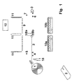
- FIG. 1 there is shown a supply 1 for the continuous belt 2 to be formed into the load sling.
- the belt 2 passes over two transverse rods 4, spaced apart with a rod 5 above and in between, a vertical movable plate 8 with rods 8b and 8a and a transverse pair of rods 6, spaced apart with a rod 7 above and in between the rods 6.
- the end of the belt 2 is fastened in a clamping device 3.
- Below the belt 2 are two vertically movable roll assemblies 10a,b.
- transverse rods 9 Above the belt 2 are transverse rods 9 which can be removed during the process. Above the rods 9 there are three partition walls 11 between which units of goods shall be stacked.
- a loading device 12 for supply of units of goods to be stacked is shown.
- the device 12 can be any suitable device for supplying the units of goods to the apparatus for forming stacks of such units surrounded by a sling formed from the belt 2.
- a knife 18 is placed immediately below the belt 2 adjacent to the belt supply 1. At the very beginning of the sling forming operation the knife 18 is raised vertically to make a central slit in the belt 2.
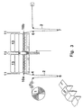
- Figure 2 shows the belt 2 stretched out to its pre-defined length. This is attained by moving the rod 5 downwards, the plate 8 and the rod 7 and simultaneously placing the roll assemblies 10a,b in their starting position for stacking of units of goods, whereby the belt 2 is stretched out to its pre-defined length.
- the belt parts resting on the respective roll assemblies 10a and 10b, and being locked in these positions, will form the bottom parts of the sling for the respective stacks of bags 13.
- the belt supply 1 is then locked until the production of the parcel of stacks of bags is concluded.
- the form of the thus pre-defined belt 2 is shown more clearly in the lower left corner of Figure 2.
- Units of goods or bags 13 are then loaded successively between the partition walls 11 and down on the rods 9 and subsequently onto the preceding bag 13.
- Figure 3 shows a further step in the production of parcels of stacks of bags.
- the rods 9 have now been removed and the bags rest on the belt 2 on the roll assemblies 10a,b.
- the plate 8 is moved upwards bringing with it by means of the rod 8b the section of the belt 2 being between roll assemblies 10a and 10b.
- FIG 4 shows the process step at which stacking of bags is finalized.
- the belt 2 now surrounds both sides and the bottom of the two stacks of bags 13.
- a loop 14 of the belt 2 is formed between the two stacks and is held in position by the rod 8b.
- This part of the belt 2 is pressed together in the transverse direction and glue might be sprayed into the folds in order to keep the loop 14 more easily in its desired form.
- the roll assemblies 10a,b have been moved downwards to a lower position than shown in Figures 2 and 3, and the belt 2 is stretched out around the two stacks of bags.
- Figure 5 shows the last step of the process of forming a parcel of self-clamping load slings.
- the clamping device 3 is moved to the left over the top of the stacks with one end of the belt 2 and joined with the other end which has been cut away from the continuous supply of belt.
- a slit-formed opening has been provided in the belt allowing the upper part of the loop 14 to be positioned above the belt 2.
- the loop 14 Prior to positioning the upper part of the loop 14 above the belt 2, the loop 14 has been gathered together, transversely, to form a lifting eye 15 at the end of the loop 14.
- the two ends of the belt 2 are joined by glue, hot melt, sewing or any other suitable joining method. If glue is applied, a plate may be placed on top of the stack A immediately beneath the joint area, and glue can be supplied between the two belt ends where a roll could then press them together to form a permanent joint.
- the units of goods or bags can be stacked into the belt in various patterns depending on the size of the units of goods.
- the type of goods which can be handled according to the invention can be bags, boxes, etc. and any types of goods which can be loaded and stacked into a sling-formed belt.
- the main proviso is that the width of the belt is about the same as the width of the stacks of units of goods.
- the production time for a parcel of bags using the apparatus according to the invention will be 1-3 minutes depending on the size of the parcels and the units of goods.
- Figure 6 shows a special arrangement for manual stacking of bags into a belt-formed sling 2.
- the belt 2 can be placed over rods 16a -d and passed 16a for forming the suspension loop 14 and then down past 17b and further around rods 17c,d,a and b around stack B and across stack A to be joined with the other end of the belt 2.
- a central slit or opening for the suspension loop can be provided in the upper area of the belt 2 in the area between the two stacks A and B.
- the bags 13 can be loaded manually inside the belt either before or after the two belt ends are joined.
- a preformed belt can also be made and supported by an assembly of eight rods after which the bags can be loaded manually into the belt having a central suspension lifting loop as described above. Additional support can be provided by a base plate or a base plate assembly.
- Such a prefabricated belt can have a pleated part encircled by a sleeve or at least one rope or strap to keep the pleats permanently together.
- the belt can be made from materials as described above and be in the form of a ready made loop or from a piece of material being joined as described above.
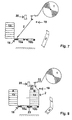
- Figure 7 shows how the belt 2 is secured to a rod 18 and running up to the belt supply 1 before the first stack of parcels 13 are placed onto the respective roll assemblies 10a and 10b.
- fig 8 it is shown that the belt 2 is placed on top of the roll assemblies 10a and 10b and the first stack B of parcels 13 is placed on 10b and its rigth side is covered by the belt 2.
- the belt 2 is pressed upward along stack B by a rod 23 placed between the assemblies 10a and 10b.
- This is how the central suspension loop 15 is formed and it is pressed and folded together or pleated and then surrounded by a sleeve 22 as shown on the small figure to the rigth of stack B. (figure 9).
- the stack A can then be placed on the assembly 10a and the belt 2 is placed along stack A by moving the rod 18 upward.
- the suspension loop is then hoisted up and secured in a clamping device 22 and the rod 23 can be released and moved back to its initial position between the assemblies 10a and 10b.
- the rod 19 is pressed to the rigth placing the cut off end of the belt 2 on top of stack B.
- the first stage of joining the belt ends together is shown.
- Glue or hot melt is supplied to the top layer of the belt by a device 21 whereupon the rod 18 is moved to the rigth placing the other end of the belt on top of the belt end previously covered with glue and the two belt ends are pressed together forming a strong joint.
- the parcel of stacks A and B surounded by the belt compricing the central suspension loop 15 is then ready for being transported out of the apparatus and a new parcel of stacks can be made.
- the stacks A and B can be surrounded by plastic sheet or film, for instance by conventional shrink wrapping, prior to being placed on the roll assemblies 10a,b.
- Figure 12-14 shows how the belt 2 can be pleated and a sleeve 22 can be secured around the pleated loop 15 according to the invention.
- Pleating and placement of a sleeve 22 around the central part of the pleated part will be performed prior to the operation shown in figure 9.
- Rods 18 and 23 will be at the same height, placing the belt 2 in a horizontal position during pleating.
- the belt 2 is first placed between two sets of guiding bars 24 as shown on figure 12.
- the bars 24 are kept at a predefined distance by end pieces 25 a,b and said distance defines the heigth of the pleats 27 (figure 13).
- Each set of bars 24 are consists of two parts, one on each side of the belt 2 and will be moved out of the belt area when pleating and placement of the sleeve 22 are completed.
- pressure cylinders 31 and 32 for horizontal movement of the bars 24 and the pleating pieces 26a,b respectively.
- the device 33 is secured to piece 26b and has a width being substanially the same as that of the pleated part 27. Glue or hotmelt is supplied to the sleeve material which is cut by a knife or similar device 34 to pre-defined length before the pleating process starts. When the pleating process is finalized, the device 33 will be immediately below the pleated part 27 (figure 13). The device 33 will then be pressed around part 27 and this part will thereby be encircled by the sleeve 22.
- This examples shows the preferred way of joining the two belt ends by glue or adhesive.
- the example further comprises tests performed for evaluating the strength of such joints.
- a test piece of polypropylene cloth being treatded with irradation (corona) had a width of 100mm and the overlapp area for the two cloth ends were about 15cm.
- a thermosetting adhesive for instance polyurethane, was applied to one of the cloth ends in 4mm stripes across the cloth, 4-6 were applied. The temperature of the adhesive was above its melting point. During the test the adhesive was supplied at 180°C. The distances between the stripes were 30mm. Immidiately after application of the adhesive the other cloth part was placed on top of the other and they were pressed together for about 10sec. Then the joint was exposed to a tension test at 60°C and at a tension rate of 200mm/min. Several tests were performed until rupture.
- the inventors have succeded in developing parcels of stacks of units that can be surrounded by a suspension loop giving safe and economic handling of such parcels.
- An apparatus essential for the economy of such a concept has also been developed and the preferred way of forming and joining the applied belt together has proved to be determening for commercializing the concept.
Landscapes
- Engineering & Computer Science (AREA)
- Mechanical Engineering (AREA)
- Packages (AREA)
- Basic Packing Technique (AREA)
- Load-Engaging Elements For Cranes (AREA)
- Auxiliary Devices For And Details Of Packaging Control (AREA)
- Battery Mounting, Suspending (AREA)
- Making Paper Articles (AREA)
- Vehicle Step Arrangements And Article Storage (AREA)
- Treatment Of Fiber Materials (AREA)
- Secondary Cells (AREA)
- Supplying Of Containers To The Packaging Station (AREA)
- Control And Other Processes For Unpacking Of Materials (AREA)
- Treatments For Attaching Organic Compounds To Fibrous Goods (AREA)
- Detergent Compositions (AREA)
Claims (15)
- Kollo mit mindestens einem Stapelpaar (A,B) von Wareneinheiten, das von einem belastbaren, selbstklemmenden Anschlagband in Form einer geschlossenen Schlaufe mit überlappenden Enden umgeben ist, die dauerhaft miteinander verbunden sind, umfassend eine mittige Tragschlaufe (14), die zwischen den Stapeln (A,B) nach oben und durch eine mittige Öffnung im oberen Teil des Anschlagbandes ragt,
dadurch gekennzeichnet, dass
das Anschlagband die Form eines Bands (2) mit einer Breite hat, die im Wesentlichen der Querbreite der Stapel (A,B) entspricht, und wobei die mittige Schlaufe (14) zusammengerafft wird, um eine Tragöse (15) zu bilden, und wobei die Bandenden dauerhaft durch Vernähen, Kleben, Schmelzkleben miteinander verbunden sind. - Kollo nach Anspruch 1,
dadurch gekennzeichnet, dass
das Anschlagband ein vorgefertigtes, schlaufenförmiges Band (2) darstellt. - Kollo nach Anspruch 1,
dadurch gekennzeichnet, dass
die mittige Schlaufe (14) einen gefältelten Teil umfasst, dessen mittiger Teil von einer Hülle mit mindestens einem Seil oder Gurt umgeben ist, um die Falten dauerhaft zusammenzuhalten. - Verfahren zum Bilden von Kolli umfassend mindestens ein Stapelpaar (A,B) von Wareneinheiten (13), das von einem belastbaren, geschlossenen, selbstklemmenden Anschlagband umgeben ist, umfassend eine mittige Tragschlaufe (14), die zwischen den Stapeln (A,B) nach oben und durch eine mittige Öffnung im oberen Teil des Anschlagbandes ragt,
dadurch gekennzeichnet, dass
das Anschlagband die Form eines Bands (2) mit einer Breite hat, die im wesentlichen der Querbreite der Stapel (A,B) entspricht und als geschlossenen Schlaufe geformt ist, die eine Tragschlaufe (14) zum Heben des Kollo umfasst, indem zunächst eine vorbestimmte Länge des Bands (2) von einem Bandvorrat (1) gebildet wird, und dann Wareneinheiten zur Bildung von Stapeln (A,B) so auf das Band (2) gesetzt werden, dass das Band diese Stapel (A,B) umgibt und zwischen den Stapeln (A,B) nach oben ragt, um eine mittige Tragschlaufe (14) zu bilden, wobei das Band (2) zusammengerafft und durch die Öffnung gezogen und zu einer Tragöse (15) geformt wird, und dass die beiden Enden des Bands (2) miteinander verbunden werden, um aus dem Band (2) eine geschlossene Schlaufe zu bilden. - Verfahren nach Anspruch 4,
dadurch gekennzeichnet, dass
die vorbestimmte Länge des Bands (2) dadurch gebildet wird, dass das Band (2) über ein Paar von Stangen (4), die auf Abstand angeordnet sind und eine vertikal bewegbare Stange (5) dazwischen aufweisen, und über eine an eine vertikal bewegbare Platte (8) befestigte Stange (8b) und dann über ein zweites Paar von Stangen (6) mit einer vertikal bewegbare Stange (7) dazwischen gezogen wird, und dass das Ende des Bands (2) dann in einer Klemmvorrichtung (3) befestigt wird, wonach die Stangen (5) und (7) gegen das Band (2) nach unten bewegt werden und die Platte (8) so nach unten bewegt wird, dass die Stange (8a) das Band (2) nach unten drückt, während die Rollensätze (10a,10b) gegen das Band (2) nach oben bewegt werden, bis das Band (2) darauf ruht, und dass der Bandvorrat (1) gesperrt wird, wenn die vorbestimmte Länge des Bands (2) abgezogen worden ist. - Verfahren nach Anspruch 4,
dadurch gekennzeichnet, dass
die vorbestimmte Länge des Bands (2) dadurch gebildet wird, dass das Band (2) vom Bandvorrat (1) und über eine Stange (18) gezogen wird, die zunächst bei dem Rollensatz (10a) positioniert ist, wonach der erste Stapel (B) in das Band (2) und auf den Rollensatz (10b) gesetzt wird, und dann wird die Tragöse (15) gebildet, indem die zwischen den Rollensätzen (10a,b) befindliche Stange (23) nach oben bewegt wird, und dass der zweite Stapel (A) dann in das Band (2) und auf den Rollensatz (10a) gesetzt wird, und die Stapel (A,B) dann vollständig durch das Band (2) umgeben werden, wenn die Stangen (18) und (19) über die Oberseiten dieser Stapel bewegt werden. - Verfahren nach Anspruch 4,
dadurch gekennzeichnet, dass
Leim oder Schmelzkleber auf mindestens einem der Endbereiche des Bands (2) aufgebracht wird, die mit Corona-Entladung behandelt worden sind, und dass die beiden Bandenden dann zusammengepresst werden. - Verfahren nach Anspruch 4,
dadurch gekennzeichnet, dass
das Band (2) während der Bildung der Tragschlaufe (15) zusammengepresst, gefältelt und von einer Hülle (22) umgeben wird. - Verfahren nach Anspruch 4,
dadurch gekennzeichnet, dass
die Hülle (22) um den gefältelten Bereich (27) der Schlaufe (15) des Bands (2) mithilfe eines gebogenen Gerätes (33) gebildet wird, indem mit Leim oder Klebstoff behaftetes Hüllenmaterial darauf platziert und auf einer Faltvorrichtung (26,b) angeordnet wird, und wobei dieses gebogene Gerät (33) um den gefältelten Bereich (27) gepresst wird, um die Hülle (22) auf der Tragschlaufe (15) zu befestigen. - Verfahren nach Anspruch 4,
dadurch gekennzeichnet, dass
das Band (2) mit einer Breite, die im Wesentlichen der Querbreite der Stapel (A,B) entspricht, zu einer geschlossenen Schlaufe geformt wird, indem das Band (2) über die Stangen (16a-d) gelegt wird, die quer zum Band (2) liegen, indem eine mittige Tragschlaufe (14) gebildet und das Band (2) um die Stangen (17a-d) gelegt wird und die beiden Enden des Bands (2) zu einem geschlossenen Anschlagband verbunden werden, und dass eine Öffnung im Band (2) zum Durchziehen der Tragschlaufe (14) bereitgestellt ist, und dass die Tragschlaufe (14) zusammengerafft ist, um eine Tragöse (15) zu bilden, und dass Wareneinheiten (13) nach Bildung des geschlossenen Anschlagbandes in dem Anschlagband gestapelt werden. - Verfahren zum Bilden von Kolli, umfassend ein Stapelpaar (A,B) von Wareneinheiten (13), die von einem belastbaren, selbstklemmenden, geschlossenen Anschlagband umgeben sind, das eine mittige Tragschlaufe (14) umfasst, die zwischen den Stapeln (A,B) nach oben und durch eine Öffnung im oberen Teil des Anschlagbandes ragt,
dadurch gekennzeichnet, dass
ein aus Band (2) vorgefertigtes Anschlagband mit einer Breite, die im Wesentlichen der Breite der Stapel (A,B) entspricht, so auf die Stangen (16a-d) gelegt wird, die sich in einem Abstand zu Stangen (17a-d) befinden, dass die Tragschlaufe (14) zwischen den beiden Gruppen von Stangen (16a-d) und Stangen (17a-d) platziert wird, und dass die Gruppen von Stangen quer zum Band (2) liegen, und dass eine Tragöse (15) vom oberen Teil der Schlaufe (14) gebildet wird, und dass die Wareneinheiten (13) dann in das Anschlagband eingebracht werden, um die Stapel (A,B) zu bilden. - Vorrichtung zum Bilden eines Kollo von mindestens zwei Stapeln (A,B) aus Wareneinheiten (13), die von einem selbstklemmenden Anschlagband umgeben sind, das eine mittige Tragschlaufe (14) umfasst, die zwischen den Stapeln (A,B) nach oben und durch eine Öffnung im oberen Teil des Anschlagbandes ragt,
dadurch gekennzeichnet, dass
das Anschlagband eine Breite hat, die im Wesentlichen der Breite der Stapel (A,B) entspricht, und dass weiterhin zwischen einem Vorrat (1) für Schlaufenmaterial und einer Klemmvorrichtung (3) zum Befestigen des äußeren Endes des Bands (2), das in ein belastbares Anschlagband zu formen ist, zwei Gruppen von Stangen (4) und (6), die jeweils vertikal bewegbare Stangen (5) und (7) dazwischen angeordnet haben, und dass mindestens zwei vertikal bewegbare Rollensätze (10a und 10b) zwischen den Stangenpaaren (4) und (6) in einem solchen Abstand angeordnet sind, dass die Platte (8) mit den Stangen (a,b) vertikal zwischen den Rollensätzen (10a und 10b) bewegt werden können, und dass die Vorrichtung weiterhin ein Mittel (12) für das Einbringen der Wareneinheiten (13) umfasst. - Vorrichtung nach Anspruch 12,
dadurch gekennzeichnet, dass
die Vorrichtung einen Satz Stangen (9) umfasst, die über den Rollensätzen (10a,b) und zwischen den Trennwänden (11) angeordnet sind, zwischen denen die Wareneinheiten (13) während des Stapelns platziert werden, und dass die Stangen (9) während des Stapelvorgangs von der Vorrichtung entfernt werden können. - Vorrichtung nach Anspruch 12, dadurch gekennzeichnet, dass die Vorrichtung eine zwischen den Rollensätzen (10a,b) platzierte, vertikal bewegbare Stange (23) zum Bilden der Tragschlaufe (15) sowie eine Klemmvorrichtung (20) zum Halten der Tragschlaufe (15) umfasst.
- Vorrichtung nach Anspruch 12,
dadurch gekennzeichnet, dass die Vorrichtung zwei Führungsschienensätze (24) umfasst, wobei die Stücke (26a,b) darauf angeordnet sind, die zum Fälteln des Bands (2) horizontal gegeneinander verschiebbar sind, und wobei die Schienen (24) in einem vorbestimmten Abstand zueinander gehalten werden, der der Höhe der gebildeten Falten (27) entspricht, und dass eine Vorrichtung (33) zum Bilden der Hülle (22) um die Tragschlaufe (15) herum an die Faltvorrichtung (26b) befestigt ist.
Applications Claiming Priority (3)
| Application Number | Priority Date | Filing Date | Title |
|---|---|---|---|
| NO965438 | 1996-12-18 | ||
| NO965438A NO305160B1 (no) | 1996-12-18 | 1996-12-18 | Stabler av enhetsgods i pakke med selvstrammende l°ftestropp og fremgangsmÕte samt apparat for fremstilling av pakken |
| PCT/NO1997/000346 WO1998026977A1 (en) | 1996-12-18 | 1997-12-18 | Parcels comprising at least two stacks of units of goods; means, method and apparatus for forming said parcels |
Publications (3)
| Publication Number | Publication Date |
|---|---|
| EP0944520A1 EP0944520A1 (de) | 1999-09-29 |
| EP0944520B1 true EP0944520B1 (de) | 2003-03-12 |
| EP0944520B8 EP0944520B8 (de) | 2003-08-06 |
Family
ID=19900198
Family Applications (1)
| Application Number | Title | Priority Date | Filing Date |
|---|---|---|---|
| EP97949273A Expired - Lifetime EP0944520B8 (de) | 1996-12-18 | 1997-12-18 | Kolli mit mindestens zwei stapeln von wareneinheiten;mittel, verfahren und gerät zum bilden solcher kolli |
Country Status (28)
| Country | Link |
|---|---|
| US (3) | US6336308B1 (de) |
| EP (1) | EP0944520B8 (de) |
| JP (1) | JP4154539B2 (de) |
| KR (1) | KR100438075B1 (de) |
| CN (1) | CN1088439C (de) |
| AR (1) | AR010806A1 (de) |
| AT (1) | ATE234220T1 (de) |
| AU (1) | AU730183B2 (de) |
| BG (1) | BG63252B1 (de) |
| BR (1) | BR9713956A (de) |
| CA (1) | CA2275427A1 (de) |
| CO (1) | CO4761100A1 (de) |
| CZ (1) | CZ294167B6 (de) |
| DE (1) | DE69719792T2 (de) |
| DK (1) | DK0944520T3 (de) |
| ES (1) | ES2194228T3 (de) |
| HU (1) | HU223372B1 (de) |
| IL (1) | IL130446A (de) |
| MA (1) | MA24428A1 (de) |
| NO (2) | NO305160B1 (de) |
| NZ (1) | NZ336295A (de) |
| PL (1) | PL185936B1 (de) |
| PT (1) | PT944520E (de) |
| RO (1) | RO118193B1 (de) |
| RU (1) | RU2202509C2 (de) |
| TR (1) | TR199901398T2 (de) |
| UA (1) | UA51760C2 (de) |
| WO (1) | WO1998026977A1 (de) |
Families Citing this family (24)
| Publication number | Priority date | Publication date | Assignee | Title |
|---|---|---|---|---|
| DE10039409A1 (de) * | 2000-08-11 | 2002-02-21 | Saint Gobain Isover G & H Ag | Grossgebinde aus Dämmstoffprodukten, insbesondere Mineralwollprodukten in Form von Platten oder Rollen |
| NO312948B1 (no) * | 2000-11-10 | 2002-07-22 | Norsk Hydro As | Fremgangsmåte og anordning for å tildanne og löfte en pakke av minst to stabler eller enheter av gods samt en apparatur for ålage en slik pakke |
| NO312949B1 (no) * | 2000-11-10 | 2002-07-22 | Norsk Hydro As | Fremgangsmåte og anordning for å tildanne og löfte en pakke av gods samt en apparatur for å tildanne slik pakke |
| NO313872B1 (no) * | 2001-03-21 | 2002-12-16 | Norsk Hydro As | Anordning for tildannelse og löfting av pakker |
| SE519011C2 (sv) * | 2001-05-31 | 2002-12-23 | Tetra Laval Holdings & Finance | Anordning för kontinuerlig gruppering av föremål på en transportbana |
| US20060283360A1 (en) * | 2005-06-20 | 2006-12-21 | Columbia/Okura Llc | Sling jig assembly for use in loading and transporting bagged and bundled products |
| NL1033209C2 (nl) * | 2006-01-12 | 2007-12-04 | Food Processing Systems | Inrichting voor het vullen van dozen of kratten. |
| US20090266037A1 (en) * | 2006-03-08 | 2009-10-29 | Delbert Odman | Box loader |
| US8015781B2 (en) * | 2006-03-08 | 2011-09-13 | Seatal Automation Systems LLC. | Box loader |
| ATE446905T1 (de) * | 2006-05-26 | 2009-11-15 | Mtc Macchine Trasformazione | Papierzuführvorrichtung für eine umreifungsmaschine zur produktion von papierollen |
| CN101541639B (zh) * | 2006-11-14 | 2011-02-16 | 爱碧世株式会社 | 装载物固定装置 |
| DE102007015751B3 (de) * | 2007-03-30 | 2008-12-24 | Khs Ag | Belade- und Palettiervorrichtung für Rollwagen und zugehöriges Verfahren |
| DE102010024548A1 (de) * | 2010-06-22 | 2011-12-22 | Multivac Sepp Haggenmüller Gmbh & Co. Kg | Verpackungssystem zum Befüllen eines Sammelbehälters mit Artikeln |
| BR112013004453B1 (pt) * | 2010-08-24 | 2020-09-29 | Cnh Industrial America Llc | Aparelho de compactação de material vegetal |
| EP2716550B1 (de) * | 2011-06-02 | 2016-01-20 | Ishida Co., Ltd. | Schachtelverpackungsvorrichtung |
| US9003747B2 (en) * | 2012-04-23 | 2015-04-14 | Alain Cerf | Process and apparatus for increasing stacking strength of film wrapped articles |
| US9051069B2 (en) * | 2012-08-22 | 2015-06-09 | De La Rue North America Inc. | Systems and methods for strapping a set of documents |
| CN103693237B (zh) * | 2013-12-05 | 2015-10-28 | 张家港市德顺机械有限责任公司 | 堆码机中的下压止跳装置 |
| RU2634158C2 (ru) * | 2016-03-16 | 2017-10-24 | Зульфия Рафаильевна Фесун | Способ извлечения груза из ёмкости |
| US10822128B2 (en) * | 2017-05-31 | 2020-11-03 | Nike, Inc. | Systems and processes for packing articles of footwear |
| CA3083095A1 (en) * | 2017-11-21 | 2019-05-31 | Fulfil Solutions, Inc. | Product handling and packaging system |
| CN108673951B (zh) * | 2018-03-28 | 2019-11-22 | 江苏南江智能装备股份有限公司 | 一种自动化纸袋穿绳装置及穿绳方法 |
| CN111453088B (zh) * | 2018-06-28 | 2021-06-11 | 绍兴市逸晨医疗科技有限公司 | 一种物流运输用快递包装箱流程化封箱设备及封箱方法 |
| CN110253954B (zh) * | 2019-06-13 | 2020-11-13 | 安徽世品佳工业产品设计有限公司 | 一种穿绳装置 |
Family Cites Families (16)
| Publication number | Priority date | Publication date | Assignee | Title |
|---|---|---|---|---|
| US1401520A (en) * | 1920-06-10 | 1921-12-27 | Clark Thread Co | Article collecting and bundling mechanism |
| US2910814A (en) * | 1952-08-12 | 1959-11-03 | Deluxe Products Corp | Method of manufacture of filter mechanism |
| FR1247293A (fr) * | 1960-02-08 | 1960-11-25 | Dispositif permettant le maintien et la manutention d'objets en vrac | |
| GB1409243A (en) * | 1971-09-07 | 1975-10-08 | Fisons Ltd | Sling |
| BE789642A (fr) * | 1971-10-05 | 1973-02-01 | Micheli Rosolino | Procede et machine a confectionner automatiquement des charges avec desbandes en materiel thermoretrecissable |
| GB1463055A (en) | 1973-01-13 | 1977-02-02 | Fisons Ltd | Sling |
| SE7712575L (sv) | 1977-11-08 | 1979-05-09 | Berrezouga Ridha | Sett for tillverkning av lyftsling med dubbel funktion |
| DE3313462A1 (de) * | 1983-04-14 | 1984-10-18 | Focke & Co, 2810 Verden | Verpackung fuer eine mehrzahl von zigaretten-packungen oder dergleichen (zigarettenstange) |
| US4617784A (en) * | 1984-01-05 | 1986-10-21 | Monarch Marking Systems, Inc. | Apparatus for stacking and banding tags |
| FI70868C (fi) | 1985-02-25 | 1986-10-27 | Lassila & Tikanoja Oy | Lyft- och ombindningsband av oegleform foer lyftande av tvao huvudsakligen lika stora och lika tunga exempelvis av balar saeckar eller roer bestaoende lass |
| RU1804426C (ru) * | 1986-05-02 | 1993-03-23 | Фераг Аг | Устройство дл сматывани в переносной рулон каскадно подводимой печатной продукции и обв зывани полученного рулона |
| SE468711B (sv) * | 1987-01-02 | 1993-03-08 | Andersson Claes Goeran | Foerpackning, innefattande ett banderolliknande foerpackningshoelje, jaemte ett foerfarande och en anordning foer framstaellning av en dylik foerpackning |
| FR2611648B1 (fr) * | 1987-03-03 | 1989-06-30 | Rochelle Pallice Sica Silo | Procede et machine de formation automatique de colis de sacs maintenus par des sangles |
| US5168989A (en) * | 1991-04-22 | 1992-12-08 | Benno Edward L | Package member, method for making packages, and packages of multiple container units |
| RU2063373C1 (ru) * | 1993-06-22 | 1996-07-10 | Петр Прокопьевич Василенко | Грузонесущий обвязочный комплект |
| US6059181A (en) * | 1998-06-04 | 2000-05-09 | Henkel Corporation | Packaging system for non-rigid materials |
-
1996
- 1996-12-18 NO NO965438A patent/NO305160B1/no unknown
-
1997
- 1997-12-18 IL IL13044697A patent/IL130446A/en not_active IP Right Cessation
- 1997-12-18 AU AU77374/98A patent/AU730183B2/en not_active Ceased
- 1997-12-18 AT AT97949273T patent/ATE234220T1/de not_active IP Right Cessation
- 1997-12-18 KR KR10-1999-7005455A patent/KR100438075B1/ko not_active Expired - Fee Related
- 1997-12-18 CN CN97180782A patent/CN1088439C/zh not_active Expired - Fee Related
- 1997-12-18 CA CA002275427A patent/CA2275427A1/en not_active Abandoned
- 1997-12-18 PT PT97949273T patent/PT944520E/pt unknown
- 1997-12-18 CZ CZ19992079A patent/CZ294167B6/cs not_active IP Right Cessation
- 1997-12-18 EP EP97949273A patent/EP0944520B8/de not_active Expired - Lifetime
- 1997-12-18 AR ARP970105985A patent/AR010806A1/es unknown
- 1997-12-18 PL PL97334302A patent/PL185936B1/pl not_active IP Right Cessation
- 1997-12-18 TR TR1999/01398T patent/TR199901398T2/xx unknown
- 1997-12-18 HU HU0002089A patent/HU223372B1/hu not_active IP Right Cessation
- 1997-12-18 DK DK97949273T patent/DK0944520T3/da active
- 1997-12-18 NZ NZ336295A patent/NZ336295A/xx unknown
- 1997-12-18 RO RO99-00693A patent/RO118193B1/ro unknown
- 1997-12-18 MA MA24905A patent/MA24428A1/fr unknown
- 1997-12-18 CO CO97074010A patent/CO4761100A1/es unknown
- 1997-12-18 BR BR9713956A patent/BR9713956A/pt not_active IP Right Cessation
- 1997-12-18 ES ES97949273T patent/ES2194228T3/es not_active Expired - Lifetime
- 1997-12-18 US US09/331,318 patent/US6336308B1/en not_active Expired - Fee Related
- 1997-12-18 DE DE69719792T patent/DE69719792T2/de not_active Expired - Fee Related
- 1997-12-18 RU RU99116009/28A patent/RU2202509C2/ru not_active IP Right Cessation
- 1997-12-18 UA UA99074096A patent/UA51760C2/uk unknown
- 1997-12-18 WO PCT/NO1997/000346 patent/WO1998026977A1/en not_active Ceased
- 1997-12-18 JP JP52757598A patent/JP4154539B2/ja not_active Expired - Fee Related
-
1999
- 1999-06-16 NO NO19992943A patent/NO314076B1/no not_active IP Right Cessation
- 1999-07-07 BG BG103559A patent/BG63252B1/bg unknown
-
2001
- 2001-11-30 US US09/996,677 patent/US6481186B2/en not_active Expired - Fee Related
- 2001-11-30 US US09/996,678 patent/US6370845B1/en not_active Expired - Fee Related
Also Published As
Similar Documents
| Publication | Publication Date | Title |
|---|---|---|
| AU730183B2 (en) | Parcels comprising at least two stacks of units of goods; means, method and apparatus for forming said parcels | |
| EP0086045B1 (de) | Verpackungs- oder Umwicklungsvorrichtung | |
| US6824346B2 (en) | Method and apparatus for handling bagged cargo | |
| EP0118112A2 (de) | Flexibler Behälter für die Lagerung von Schüttgutern und Verfahren zu seiner Herstellung | |
| KR101377055B1 (ko) | 컨테이너백 | |
| US20040050018A1 (en) | Method and means for forming and lifting parcels or packages comprising at least two stacks or units of goods, and an apparatus for forming such parcels | |
| MXPA99005668A (en) | Parcels comprising at least two stacks of units of goods;means, method and apparatus for forming said parcels | |
| US20250296791A1 (en) | Item supporter for shipping and methods of use | |
| RU2787606C1 (ru) | Мягкий контейнер для транспортировки и хранения насыпных грузов | |
| WO2002038485A1 (en) | A method and means for forming and lifting parcels of goods and an apparatus for forming such parcels | |
| JP2550547Y2 (ja) | 引抜きバンドコンテナ | |
| TH21667B (th) | หีบห่อที่ประกอบด้วยกองอย่างน้อยสองกองของหน่วยของสินค้าวิธีการและบริภัณฑ์สำหรับการเตรียมหีบห่อที่กล่าวมาแล้ว | |
| TH36981A (th) | หีบห่อที่ประกอบด้วยกองอย่างน้อยสองกองของหน่วยของสินค้าวิธีการและบริภัณฑ์สำหรับการเตรียมหีบห่อที่กล่าวมาแล้ว | |
| JPS6026527A (ja) | 荷降し台 | |
| JPS6216932A (ja) | 荷降し台 | |
| NZ221343A (en) | Flexible bulk container with permanent lifting handle made from tubular material |
Legal Events
| Date | Code | Title | Description |
|---|---|---|---|
| PUAI | Public reference made under article 153(3) epc to a published international application that has entered the european phase |
Free format text: ORIGINAL CODE: 0009012 |
|
| 17P | Request for examination filed |
Effective date: 19990719 |
|
| AK | Designated contracting states |
Kind code of ref document: A1 Designated state(s): AT BE CH DE DK ES FI FR GB GR IE IT LI NL PT SE |
|
| 17Q | First examination report despatched |
Effective date: 20000322 |
|
| GRAG | Despatch of communication of intention to grant |
Free format text: ORIGINAL CODE: EPIDOS AGRA |
|
| GRAG | Despatch of communication of intention to grant |
Free format text: ORIGINAL CODE: EPIDOS AGRA |
|
| GRAH | Despatch of communication of intention to grant a patent |
Free format text: ORIGINAL CODE: EPIDOS IGRA |
|
| GRAH | Despatch of communication of intention to grant a patent |
Free format text: ORIGINAL CODE: EPIDOS IGRA |
|
| GRAA | (expected) grant |
Free format text: ORIGINAL CODE: 0009210 |
|
| AK | Designated contracting states |
Designated state(s): AT BE CH DE DK ES FI FR GB GR IE IT LI NL PT SE |
|
| REG | Reference to a national code |
Ref country code: GB Ref legal event code: FG4D |
|
| REG | Reference to a national code |
Ref country code: CH Ref legal event code: EP |
|
| REG | Reference to a national code |
Ref country code: IE Ref legal event code: FG4D |
|
| REF | Corresponds to: |
Ref document number: 69719792 Country of ref document: DE Date of ref document: 20030417 Kind code of ref document: P |
|
| REG | Reference to a national code |
Ref country code: CH Ref legal event code: NV Representative=s name: DR. LUSUARDI AG |
|
| REG | Reference to a national code |
Ref country code: SE Ref legal event code: TRGR |
|
| REG | Reference to a national code |
Ref country code: DK Ref legal event code: T3 |
|
| REG | Reference to a national code |
Ref country code: GR Ref legal event code: EP Ref document number: 20030402168 Country of ref document: GR |
|
| RAP2 | Party data changed (patent owner data changed or rights of a patent transferred) |
Owner name: NORSK HYDRO ASA |
|
| NLT2 | Nl: modifications (of names), taken from the european patent patent bulletin |
Owner name: NORSK HYDRO ASA |
|
| NLXE | Nl: other communications concerning ep-patents (part 3 heading xe) |
Free format text: PAT. BUL. 07/2003 PAGE 1027: CORR.: NORSK HYDRO ASA. |
|
| ET | Fr: translation filed | ||
| REG | Reference to a national code |
Ref country code: ES Ref legal event code: FG2A Ref document number: 2194228 Country of ref document: ES Kind code of ref document: T3 |
|
| NLXE | Nl: other communications concerning ep-patents (part 3 heading xe) |
Free format text: PAT. BUL. 07/2003 PAGE 1027: CORR.: NORSK HYDRO ASA |
|
| PLBE | No opposition filed within time limit |
Free format text: ORIGINAL CODE: 0009261 |
|
| STAA | Information on the status of an ep patent application or granted ep patent |
Free format text: STATUS: NO OPPOSITION FILED WITHIN TIME LIMIT |
|
| 26N | No opposition filed |
Effective date: 20031215 |
|
| PGFP | Annual fee paid to national office [announced via postgrant information from national office to epo] |
Ref country code: AT Payment date: 20041213 Year of fee payment: 8 |
|
| PGFP | Annual fee paid to national office [announced via postgrant information from national office to epo] |
Ref country code: CH Payment date: 20041215 Year of fee payment: 8 |
|
| PGFP | Annual fee paid to national office [announced via postgrant information from national office to epo] |
Ref country code: GR Payment date: 20051111 Year of fee payment: 9 |
|
| PGFP | Annual fee paid to national office [announced via postgrant information from national office to epo] |
Ref country code: SE Payment date: 20051206 Year of fee payment: 9 |
|
| PGFP | Annual fee paid to national office [announced via postgrant information from national office to epo] |
Ref country code: FR Payment date: 20051208 Year of fee payment: 9 |
|
| PGFP | Annual fee paid to national office [announced via postgrant information from national office to epo] |
Ref country code: FI Payment date: 20051214 Year of fee payment: 9 |
|
| PGFP | Annual fee paid to national office [announced via postgrant information from national office to epo] |
Ref country code: DE Payment date: 20051215 Year of fee payment: 9 |
|
| PG25 | Lapsed in a contracting state [announced via postgrant information from national office to epo] |
Ref country code: AT Free format text: LAPSE BECAUSE OF NON-PAYMENT OF DUE FEES Effective date: 20051218 |
|
| PG25 | Lapsed in a contracting state [announced via postgrant information from national office to epo] |
Ref country code: LI Free format text: LAPSE BECAUSE OF NON-PAYMENT OF DUE FEES Effective date: 20051231 Ref country code: CH Free format text: LAPSE BECAUSE OF NON-PAYMENT OF DUE FEES Effective date: 20051231 |
|
| PGFP | Annual fee paid to national office [announced via postgrant information from national office to epo] |
Ref country code: ES Payment date: 20060118 Year of fee payment: 9 |
|
| PGFP | Annual fee paid to national office [announced via postgrant information from national office to epo] |
Ref country code: BE Payment date: 20060217 Year of fee payment: 9 |
|
| REG | Reference to a national code |
Ref country code: CH Ref legal event code: PL |
|
| PGFP | Annual fee paid to national office [announced via postgrant information from national office to epo] |
Ref country code: DK Payment date: 20061213 Year of fee payment: 10 |
|
| PG25 | Lapsed in a contracting state [announced via postgrant information from national office to epo] |
Ref country code: FI Free format text: LAPSE BECAUSE OF NON-PAYMENT OF DUE FEES Effective date: 20061218 |
|
| PG25 | Lapsed in a contracting state [announced via postgrant information from national office to epo] |
Ref country code: SE Free format text: LAPSE BECAUSE OF NON-PAYMENT OF DUE FEES Effective date: 20061219 |
|
| PG25 | Lapsed in a contracting state [announced via postgrant information from national office to epo] |
Ref country code: BE Free format text: LAPSE BECAUSE OF NON-PAYMENT OF DUE FEES Effective date: 20061231 |
|
| PGFP | Annual fee paid to national office [announced via postgrant information from national office to epo] |
Ref country code: IT Payment date: 20061231 Year of fee payment: 10 |
|
| PG25 | Lapsed in a contracting state [announced via postgrant information from national office to epo] |
Ref country code: DE Free format text: LAPSE BECAUSE OF NON-PAYMENT OF DUE FEES Effective date: 20070703 |
|
| EUG | Se: european patent has lapsed | ||
| REG | Reference to a national code |
Ref country code: FR Ref legal event code: ST Effective date: 20070831 |
|
| BERE | Be: lapsed |
Owner name: *NORSK HYDRO ASA Effective date: 20061231 |
|
| REG | Reference to a national code |
Ref country code: ES Ref legal event code: FD2A Effective date: 20061219 |
|
| PG25 | Lapsed in a contracting state [announced via postgrant information from national office to epo] |
Ref country code: FR Free format text: LAPSE BECAUSE OF NON-PAYMENT OF DUE FEES Effective date: 20070102 Ref country code: ES Free format text: LAPSE BECAUSE OF NON-PAYMENT OF DUE FEES Effective date: 20061219 |
|
| PGFP | Annual fee paid to national office [announced via postgrant information from national office to epo] |
Ref country code: GB Payment date: 20071218 Year of fee payment: 11 |
|
| PGFP | Annual fee paid to national office [announced via postgrant information from national office to epo] |
Ref country code: PT Payment date: 20071123 Year of fee payment: 11 |
|
| REG | Reference to a national code |
Ref country code: DK Ref legal event code: EBP |
|
| PG25 | Lapsed in a contracting state [announced via postgrant information from national office to epo] |
Ref country code: GR Free format text: LAPSE BECAUSE OF NON-PAYMENT OF DUE FEES Effective date: 20070704 |
|
| PG25 | Lapsed in a contracting state [announced via postgrant information from national office to epo] |
Ref country code: DK Free format text: LAPSE BECAUSE OF NON-PAYMENT OF DUE FEES Effective date: 20080102 |
|
| PGFP | Annual fee paid to national office [announced via postgrant information from national office to epo] |
Ref country code: NL Payment date: 20081216 Year of fee payment: 12 |
|
| REG | Reference to a national code |
Ref country code: PT Ref legal event code: MM4A Free format text: LAPSE DUE TO NON-PAYMENT OF FEES Effective date: 20090618 |
|
| GBPC | Gb: european patent ceased through non-payment of renewal fee |
Effective date: 20081218 |
|
| PG25 | Lapsed in a contracting state [announced via postgrant information from national office to epo] |
Ref country code: PT Free format text: LAPSE BECAUSE OF NON-PAYMENT OF DUE FEES Effective date: 20090618 Ref country code: IT Free format text: LAPSE BECAUSE OF NON-PAYMENT OF DUE FEES Effective date: 20071218 |
|
| PGFP | Annual fee paid to national office [announced via postgrant information from national office to epo] |
Ref country code: IE Payment date: 20071220 Year of fee payment: 11 |
|
| REG | Reference to a national code |
Ref country code: IE Ref legal event code: MM4A |
|
| PG25 | Lapsed in a contracting state [announced via postgrant information from national office to epo] |
Ref country code: IE Free format text: LAPSE BECAUSE OF NON-PAYMENT OF DUE FEES Effective date: 20081218 |
|
| PG25 | Lapsed in a contracting state [announced via postgrant information from national office to epo] |
Ref country code: GB Free format text: LAPSE BECAUSE OF NON-PAYMENT OF DUE FEES Effective date: 20081218 |
|
| REG | Reference to a national code |
Ref country code: NL Ref legal event code: V1 Effective date: 20100701 |
|
| PG25 | Lapsed in a contracting state [announced via postgrant information from national office to epo] |
Ref country code: NL Free format text: LAPSE BECAUSE OF NON-PAYMENT OF DUE FEES Effective date: 20100701 |