EP0943770A2 - Penture de porte ou de fenêtre - Google Patents
Penture de porte ou de fenêtre Download PDFInfo
- Publication number
- EP0943770A2 EP0943770A2 EP99103763A EP99103763A EP0943770A2 EP 0943770 A2 EP0943770 A2 EP 0943770A2 EP 99103763 A EP99103763 A EP 99103763A EP 99103763 A EP99103763 A EP 99103763A EP 0943770 A2 EP0943770 A2 EP 0943770A2
- Authority
- EP
- European Patent Office
- Prior art keywords
- hinge
- axle
- door
- bushing
- recess
- Prior art date
- Legal status (The legal status is an assumption and is not a legal conclusion. Google has not performed a legal analysis and makes no representation as to the accuracy of the status listed.)
- Granted
Links
- 238000007789 sealing Methods 0.000 claims description 7
- 239000000945 filler Substances 0.000 claims description 5
- 238000003780 insertion Methods 0.000 claims description 5
- 230000037431 insertion Effects 0.000 claims description 5
- 230000015572 biosynthetic process Effects 0.000 claims description 3
- 238000005755 formation reaction Methods 0.000 claims description 3
- 230000000284 resting effect Effects 0.000 claims 1
- 230000005540 biological transmission Effects 0.000 description 3
- 238000012546 transfer Methods 0.000 description 3
- 230000008878 coupling Effects 0.000 description 2
- 238000010168 coupling process Methods 0.000 description 2
- 238000005859 coupling reaction Methods 0.000 description 2
- 238000006073 displacement reaction Methods 0.000 description 2
- 238000004519 manufacturing process Methods 0.000 description 2
- 238000010276 construction Methods 0.000 description 1
- 239000007822 coupling agent Substances 0.000 description 1
- 238000013461 design Methods 0.000 description 1
- 230000000694 effects Effects 0.000 description 1
- 230000003203 everyday effect Effects 0.000 description 1
- 230000002349 favourable effect Effects 0.000 description 1
- 210000003746 feather Anatomy 0.000 description 1
- 238000009434 installation Methods 0.000 description 1
- 230000002427 irreversible effect Effects 0.000 description 1
- 239000002184 metal Substances 0.000 description 1
- 230000003287 optical effect Effects 0.000 description 1
- 238000005096 rolling process Methods 0.000 description 1
- 238000003860 storage Methods 0.000 description 1
- 238000012549 training Methods 0.000 description 1
- 230000003313 weakening effect Effects 0.000 description 1
Images


Classifications
-
- E—FIXED CONSTRUCTIONS
- E05—LOCKS; KEYS; WINDOW OR DOOR FITTINGS; SAFES
- E05D—HINGES OR SUSPENSION DEVICES FOR DOORS, WINDOWS OR WINGS
- E05D7/00—Hinges or pivots of special construction
- E05D7/0009—Adjustable hinges
- E05D7/0018—Adjustable hinges at the hinge axis
- E05D7/0027—Adjustable hinges at the hinge axis in an axial direction
-
- E—FIXED CONSTRUCTIONS
- E05—LOCKS; KEYS; WINDOW OR DOOR FITTINGS; SAFES
- E05D—HINGES OR SUSPENSION DEVICES FOR DOORS, WINDOWS OR WINGS
- E05D7/00—Hinges or pivots of special construction
- E05D7/0009—Adjustable hinges
- E05D7/0018—Adjustable hinges at the hinge axis
- E05D7/0045—Adjustable hinges at the hinge axis in a radial direction
- E05D7/0054—Adjustable hinges at the hinge axis in a radial direction by means of eccentric parts
-
- E—FIXED CONSTRUCTIONS
- E05—LOCKS; KEYS; WINDOW OR DOOR FITTINGS; SAFES
- E05D—HINGES OR SUSPENSION DEVICES FOR DOORS, WINDOWS OR WINGS
- E05D3/00—Hinges with pins
- E05D3/02—Hinges with pins with one pin
- E05D2003/025—Hinges with pins with one pin having three knuckles
-
- E—FIXED CONSTRUCTIONS
- E05—LOCKS; KEYS; WINDOW OR DOOR FITTINGS; SAFES
- E05D—HINGES OR SUSPENSION DEVICES FOR DOORS, WINDOWS OR WINGS
- E05D5/00—Construction of single parts, e.g. the parts for attachment
- E05D5/10—Pins, sockets or sleeves; Removable pins
- E05D2005/102—Pins
- E05D2005/106—Pins with non-cylindrical portions
-
- E—FIXED CONSTRUCTIONS
- E05—LOCKS; KEYS; WINDOW OR DOOR FITTINGS; SAFES
- E05D—HINGES OR SUSPENSION DEVICES FOR DOORS, WINDOWS OR WINGS
- E05D7/00—Hinges or pivots of special construction
- E05D7/10—Hinges or pivots of special construction to allow easy separation or connection of the parts at the hinge axis
- E05D7/1005—Hinges or pivots of special construction to allow easy separation or connection of the parts at the hinge axis by axially moving free pins, balls or sockets
- E05D2007/1038—Hinges or pivots of special construction to allow easy separation or connection of the parts at the hinge axis by axially moving free pins, balls or sockets by axially moving free sockets
-
- E—FIXED CONSTRUCTIONS
- E05—LOCKS; KEYS; WINDOW OR DOOR FITTINGS; SAFES
- E05D—HINGES OR SUSPENSION DEVICES FOR DOORS, WINDOWS OR WINGS
- E05D5/00—Construction of single parts, e.g. the parts for attachment
- E05D5/10—Pins, sockets or sleeves; Removable pins
- E05D5/12—Securing pins in sockets, movably or not
- E05D5/128—Securing pins in sockets, movably or not the pin having a recess or through-hole engaged by a securing member
-
- E—FIXED CONSTRUCTIONS
- E05—LOCKS; KEYS; WINDOW OR DOOR FITTINGS; SAFES
- E05D—HINGES OR SUSPENSION DEVICES FOR DOORS, WINDOWS OR WINGS
- E05D5/00—Construction of single parts, e.g. the parts for attachment
- E05D5/10—Pins, sockets or sleeves; Removable pins
- E05D5/14—Construction of sockets or sleeves
-
- E—FIXED CONSTRUCTIONS
- E05—LOCKS; KEYS; WINDOW OR DOOR FITTINGS; SAFES
- E05Y—INDEXING SCHEME ASSOCIATED WITH SUBCLASSES E05D AND E05F, RELATING TO CONSTRUCTION ELEMENTS, ELECTRIC CONTROL, POWER SUPPLY, POWER SIGNAL OR TRANSMISSION, USER INTERFACES, MOUNTING OR COUPLING, DETAILS, ACCESSORIES, AUXILIARY OPERATIONS NOT OTHERWISE PROVIDED FOR, APPLICATION THEREOF
- E05Y2900/00—Application of doors, windows, wings or fittings thereof
- E05Y2900/10—Application of doors, windows, wings or fittings thereof for buildings or parts thereof
- E05Y2900/13—Type of wing
- E05Y2900/132—Doors
-
- E—FIXED CONSTRUCTIONS
- E05—LOCKS; KEYS; WINDOW OR DOOR FITTINGS; SAFES
- E05Y—INDEXING SCHEME ASSOCIATED WITH SUBCLASSES E05D AND E05F, RELATING TO CONSTRUCTION ELEMENTS, ELECTRIC CONTROL, POWER SUPPLY, POWER SIGNAL OR TRANSMISSION, USER INTERFACES, MOUNTING OR COUPLING, DETAILS, ACCESSORIES, AUXILIARY OPERATIONS NOT OTHERWISE PROVIDED FOR, APPLICATION THEREOF
- E05Y2900/00—Application of doors, windows, wings or fittings thereof
- E05Y2900/10—Application of doors, windows, wings or fittings thereof for buildings or parts thereof
- E05Y2900/13—Type of wing
- E05Y2900/148—Windows
Definitions
- the invention relates to a door or window hinge, with a frame hinge and a wing hinge, which means a pivot bearing axis are hinged together, with a threaded part surrounding the pivot bearing axis, the is supported on the frame band load-bearing and with a Axle bush loaded on the sash hinge in thread engagement stands, which is acted upon by rotary adjusting means.
- a door or window hinge with the aforementioned features is generally known from WO 96/23124.
- Window or door hinges have adjustment devices which make it possible to that the tapes were built within certain tolerances Differences in doors or windows due to height adjustment, Side adjustment or contact pressure can compensate.
- the WO 96/23124 shows a height-adjustable hinge for window or door shutters. There is one in a band sleeve non-rotatably mounted hinge. Located inside the tape sleeve there is still an intermediate adjusting bush. There is also a cap that functions as a cover the tape sleeve met upwards. Through this cap the adjusting bush can be twisted through with a tool and lifts the band sleeve by twisting it on a thread the band bushing.
- the structure has a multilayer Arrangement of different caps and sockets.
- the invention is based on the object a door or window hinge with the features mentioned above so improve that in a simple way a height adjustment of a possibly very difficult one Door or window sash is possible. Furthermore should the band can be expanded for multi-part wing bands.
- This arrangement is characterized by a special simple construction. There will not be multiple caps or sockets pushed over each other and attached to each other, but it is only a torsionally positive assembly of the Swivel bearing axis with the axle bushing and the rotary adjustment means required are located on the swivel bearing axis.
- Twist the pivot bearing axis which is easy from the outside with a Tool is possible, the height adjustment of the belt can be achieved with relatively little effort.
- the entire structure is compact and easy to assemble. Because the rotary adjustment means are built into the pivot bearing axis is also easily a multi-part structure, i.e. a structure with e.g. three band parts possible. This gives one good hold also for heavy sashes, e.g. at Fire doors or large windows. Even that heavy Sashes can be adjusted in the Readjust the pivot bearing axis when installed.
- the tape can be designed so that the assembly the pivot bearing axis and the axle bushing of the wing hinge Insert the axle through the socket into the axle socket of the Frame strap until it hits a stop.
- This simple one Assembly of swivel bearing axis and axle bushing, the essential Form parts for the height adjustment of the frame hinge, is very helpful, especially when assembling heavy ones Wings. Accordingly, it also enables easy expansion and an easy adjustment.
- the parts needed for assembly can be used due to the insertion mechanism made in a similar shape in each band part be. This means an economically favorable production method.
- the torsionally positive assembly the swivel bearing axis and the axle bush with one Insert part is effected, both in an axially open Socket recess engages, as well as in a socket side open axle recess.
- the insert is easy to use and interchangeable.
- the structure enables simple power transmission from the swivel bearing axis to the axle bush.
- the Insert part enables recesses as coupling means.
- the socket recess on the axis insertion side according to the cross section of the insert is open.
- the insert is therefore minimal Game can be used. It enables a direct, namely free of space Power transmission without delay.
- the axis recess in the axial Towards an engaging outer circumference of the axle bushing or the insert is adapted.
- a projection on the axle bush or an insert used causes all the more better twist-fit, the more large contact surfaces the Recess in the axis, i.e. in the axial direction is expanded as far as possible.
- the power transmission is through this arrangement improved.
- the arrangement more stable.
- the insert can be axially parallel Sliding into the axle bushing can be installed smoothly.
- a special training option for the band is that the insert part has an arched or corrugated leaf spring is, with its curvature or with its waves, in one of the Envelope of the spring shape corresponding to the curved recess intervenes.
- the leaf spring enables a good positive and non-positive connection of the swivel bearing axis to the axle bush is guaranteed. Manufacturing tolerances the recesses can be compensated.
- the leaf spring enables an additional hold or a backup of the Axle bush also axially relative to the pivot bearing axis.
- the leaf spring widened two Has ends that are in an undercut of a T-shaped Engage the socket recess. By intervening in the The undercut ensures a secure hold of the leaf spring.
- the leaf spring is held radially in a form-fitting manner. Turning the swivel bearing axis does not cause displacement the leaf spring.
- the leaf spring can be used with the axle bush can be assembled captively as a unit, even if the pivot bearing axis is not yet installed.
- axle bushing is eccentric Bearing axis bore, and the T-shaped bushing recess at the radially strongest point of the axle bush lies.
- An eccentric hole in the axle bush for the Swivel bearing axis enables side adjustment.
- By the eccentric arrangement results in a radially different one Axle bushing thickness.
- Socket recesses of different sizes can be used to be incorporated, the use of different large insert parts or leaf springs.
- the order at the radially strongest point means the lowest possible Weakening of the axle bush.
- Such an embodiment is advantageous in which the Threaded part engages with an external thread of the axle bush stands.
- the axle bushing can be comparatively long be formed and thus for a radially large area Provide support for the swivel bearing axis.
- the threaded part in a simple manner with a section surrounding it of a band body are connected in a rotationally positive manner.
- the threaded part has comparatively large radii, so that accordingly low surface pressures in the area of Thread engagement with the axle bushing and its further provide axial support.
- the rotary adjustment means has an inner non-circular recess is at one end of the pivot bearing axis.
- the inner non-circular recess e.g. a Intervene from outside, which prevents the twisting of the Swivel bearing axis and thus a height adjustment of the wing enables. Since the rotary adjustment means at the end of the Pivot bearing axis can be shorter or longer Swivel bearing axles for two-part or multi-part, in particular three-part tapes are used without the Means for the positive locking between the pivot bearing axis and the axle bushing would have to be changed.
- a hinge body of the wing hinge supported above the threaded part on the axle bush and is radially non-rotatably connected with formations and the threaded part axially displaceable but encompasses torsion-proof.
- no adjustment of the height adjustment e.g. is caused by pivoting the wing.
- the Height adjustment should be in normal everyday operation of the Tape to be irreversible. Since the axle bushing around the inside Pivot bearing axis is attached within the belt body, no built-in parts of the belt can be seen from the outside. Either the threaded part and the axle bush move together with the hinge of the wing hinge.
- the threaded part on a Bearing ring is supported, which rests on the frame band and the threaded part with a ring projection inside the axle bush surrounds.
- the ring projection ensures a radial positive fit and a secure fit of the bearing ring. Because the ring projection lies inside the band body, it is from the outside not recognizable and the wing hinge or hinge body guaranteed a good impression.
- the bearing ring enables further that even with an eccentric attitude the pivot bearing axis by turning the axle bushing none There is a reduction in the support on the frame band.
- the hinge body of the wing hinge is provided on the axis insertion side with a recess which a recess required for receiving the threaded part corresponds, and with a radially supporting the axle bush Filler is filled. Since the recesses on the The wing hinge can correspond to the ends of the axle bushing be used for the right-hand stop as well as for Left stop. The filler determines a radially secure Stop above the torsionally positive connection of the Swivel axis with the axle bush.
- the design of the frame band with at least a wing hinge and two frame hinges ensures one good radial support of the swivel bearing axis and thus one secure hold of the wing when it causes high loads.
- the rotary adjustment of the swivel bearing axis can in the upper end of the pivot bearing axis within the upper Be arranged frame tape.
- the one from the wing hinge Arrangement of the rotary adjustment means prevents the desired Height adjustment not. It is only necessary make the pivot bearing axis longer. It is stable enough to withstand larger turning forces easily to the distant point of the positive locking transfer.
- the sealing ring ensures a handsome optical impression. It can also be a pollution prevent.
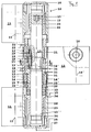
- the illustrated embodiment is a three-part Door hinge, consisting essentially of a hinge 12, the articulated by means of a pivot bearing axis 13 with two Frame straps 11 is connected.
- the wing hinge 12 is with a mounting screw 16 shown for example attached and not shown a wing of the door further attachment points 16 '.
- the frame bands 11 are each on a frame of the door, not shown attached, for example at the specified attachment points 11 '.
- the wing hinge 12 has a sleeve-like hinge body 12 ', in which the pivot bearing axis 13 is radial supporting axle bush 15 is located.
- axle bushings 23, which each within the sleeve-like band body 26 of the upper or of the lower frame band 11. All axle bushings 15, 23 are traditionally designed to be the one to them requirements regarding the resilience and the Ease of movement must suffice. For example, they exist made of plastic or cast metal.
- axle bushing 15 is provided with an eccentric bearing axis bore 15 IV , in which case the bushing axis 25 is arranged eccentrically to the longitudinal axis 27 of the pivot bearing axis 13 by the distance shown.
- the axle bushings 23, which likewise have eccentric bearing axis bores must also be adjusted accordingly. If the axle bushings 15, 23 are only rotated by 90 degrees, this results in a correspondingly combined side and pressure adjustment with pressure increase or pressure reduction, depending on the setting direction.
- end caps 28 are used, for example, which engage with protrusions (not shown in detail) in outer recesses 29 of the axle bushings 15, 23 and at the same time also in inner recesses 30 of the band body 26, which are designed according to FIG Cross section is filled by the mentioned cap projections, so that a rotation of the axle bushings 15,23 is not possible without removing the caps 28 beforehand.
- the band body 12 ' has an annular support surface 31 on a corresponding annular support surface an annular projection 32 rests on the support surface 31 engages.
- an annular projection 32 rests on the support surface 31 engages.
- Such coupling agents are for example Projection 32 cams and recesses adapted to these cams of the band body 12 '.
- the axle bushing 12 ' is provided below the projection 32 on its outer circumference with an external thread 15 V which engages in an internal thread of a threaded part 14.
- the threaded part 14 thus encompasses the lower end of the axle bushing 12 'and also the pivot bearing axis 13.
- the threaded part 14 is supported on a bearing ring 20 which rests on the frame band 11.
- the bearing ring 20 has an annular projection 20 which surrounds the threaded part 14 on the outside, but is arranged inside the band body 12 ', so that there is a corresponding sealing of the threaded area.
- the bearing ring 20 covers the joint between the lower end of the hinge body 12 'and the upper end of the hinge body 26 of the lower frame hinge 11.
- a sealing ring 22 covers a joint between the upper end of the axle bushing 12' and the lower end of the hinge body 26 of the upper frame hinge 11.
- the pivot bearing axis 13 is located in an elongated hole 20 ′′ or 22 ′, so that corresponding space is available for adjusting the pivot bearing axis 13 when the bearing bushes 15, 23 twist to adjust the wing position because the rings 20, 22 are radially positively arranged in their band bodies 12 ', 26.
- the three-part band shown is mainly for larger wing loads thought. Despite such larger wing loads the wing must be able to be pivoted easily, so without larger storage or Frictional forces result. This can be done especially at the load transfer point the wing hinge 12 to the frame hinge 11 occur, So at the bottom of the bearing ring 20.
- the lower frame hinge is to avoid greater frictional resistance 11 provided on the sash hinge with a roller bearing 33, which in turn is supported on the wing bush 23, which again with a support projection 34 on a support ring surface 35 of the band body 26 rests.
- the upper frame band 11 is the lower frame band 11 trained accordingly except for the rolling bearing. It broadcasts no axial forces, but only serves the radial support of the pivot bearing axis 13. This is the upper frame hinge 11 as far axially from the wing hinge 12 posted that the distance shown in Fig.1 between the bearing bush 23 and the sealing ring 22 results. The distance is such that a height adjustment the wing hinge 12 is not hindered.
- the arrangement shown the axle bush 23 at the upper end of the pivot bearing axis is saved in a manner not shown, e.g. With a grub screw that fixes the bushing 23 on the body 26.
- the thread engagement between the bearing bush 15 and the Threaded part 14 opens up the possibility of height adjustment to effect using the pivot bearing axis 13.
- a Rotation adjustment of the bearing bush 15 leads to the fact that Bearing bush 15 depending on the direction of rotation within the threaded part 14 raises or lowers, the threaded part 14 with is connected to the band body 12 'in a rotationally fixed manner, e.g. with the shown projections 14 'in corresponding axially parallel Grooves of a recess 12 '' 'engage which the threaded part 14 receives.
- the Socket 15 can be the torsionally positive connection between its projection 32 and the support surface 31 of the band body 12 'can be overcome.
- axis bushing 15 To cause the axis bushing 15 to twist these are connected to the pivot bearing axis 13 in a rotationally locking manner, which in turn rotary adjustment means 17 in the form of a Has non-circular recess.
- the inner non-circular recess is a hexagon socket into which an Allen key is inserted can be removed when the cap 28 is removed. A twist such a key leads to a corresponding one Rotation of the pivot bearing axis 13 and with a Transfer insert 19 to the axle bushing 15.
- the insert 19 is a curved leaf spring, which has two facing ends 19 ''.
- This Ends 19 ′′ are widened according to FIG. 2 and engage in one Undercut 15 '' 'of a T-shaped socket recess 15 '.
- This socket recess 15 ' is open vertically at the top.
- Fig. 3 insert 19 shown which has the shape of a corrugated Has leaf spring.
- the axis recess 13 ' is essentially in the axial direction so arched that its curvature of the envelope of the Spring shape corresponds.
- the tolerances can be designed in this way be that the leaf spring is slightly compressed radially becomes. The result is a correspondingly tighter Seat of the pivot bearing axis 13 in the axle bushing 15.
- the pivot bearing axis 13 is assembled with the wing hinge 12 in such a way that it is inserted through the bearing axis bore of the upper frame hinge into the bearing axis bore 15 IV of the axle bushing 15 and is pushed so far until the leaf spring engages in the bushing recess 15 '.
- the pivot bearing axis 13 is accordingly removed while overcoming the latching force of the leaf spring in the opposite axial direction, provided that it is not pulled out as well.
- the pivot bearing axis 13 is inserted by limited an attack.
- Fig.1 is in the lower frame band 11 a stop 24 in the form of an annular projection of the axle bushing 23 shown.
- the insert 19 serve as a sling. This is especially true when a rigid insert instead of the leaf spring is used, for example a feather key.
- the pivot bearing axis 13 would have to be up to be slotted continuously at the bottom so that the Axis 13 with its slot pushed over the rigid key can be.
- the wing hinge 12 is for both right and for Left stop trained. This is done by simply turning reached, then the one for receiving the threaded part 14 serving recess 12 '' 'comes to lie above.
- the recess 12 ′′ shown at the top in FIG. 1 comes to the bottom lie and can grip around the threaded part 14, since they are also is formed as the recess 12 '' '. So that the radial support the pivot bearing axis guaranteed in any case , the recess 12 ′′ or 12 '' 'provided with a filler 21, which is the radial support between the axle bushing 15 and the belt body 12 ' ensures, as well as the axial support of the sealing ring 22.
- the pivot bearing axis 13 points in the center of the sash hinge 12 a constriction 36 with which the rotation of the pivot bearing axis 13 when assembled with the wing hinge 12 before Locking the leaf spring is facilitated. Also intervenes in this constriction 36 a cross pin to secure the axial position the pivot bearing axis 13.
- FIG. 2 it is shown how the wing hinge 12 and a Frame hinge 11 with fastening screws 16 for fastening are formed on a frame.
- the screws 16 grip each in a fastening nut 37 with guide means 38 for rod guidance behind a hole in the frame is formed, in which the wing hinge 12 and the frame hinge 11 each engage with centering bushes 39.
- a cover cap 40 is from the frame side with a fastening screw 41 attached to the wing hinge, from the back of the wing hinge 12 ago, so that they only when open Door leaf can be removed, which prevents the fastening screws 16 with the door leaf closed can be turned out.
Landscapes
- Engineering & Computer Science (AREA)
- Mechanical Engineering (AREA)
- Hinges (AREA)
- Support Of The Bearing (AREA)
- Window Of Vehicle (AREA)
- Liquid Crystal (AREA)
- Pivots And Pivotal Connections (AREA)
Applications Claiming Priority (2)
| Application Number | Priority Date | Filing Date | Title |
|---|---|---|---|
| DE29804967U | 1998-03-20 | ||
| DE29804967U DE29804967U1 (de) | 1998-03-20 | 1998-03-20 | Tür- oder Fensterband |
Publications (3)
| Publication Number | Publication Date |
|---|---|
| EP0943770A2 true EP0943770A2 (fr) | 1999-09-22 |
| EP0943770A3 EP0943770A3 (fr) | 2003-01-15 |
| EP0943770B1 EP0943770B1 (fr) | 2005-08-24 |
Family
ID=8054421
Family Applications (1)
| Application Number | Title | Priority Date | Filing Date |
|---|---|---|---|
| EP99103763A Expired - Lifetime EP0943770B1 (fr) | 1998-03-20 | 1999-02-26 | Penture de porte ou de fenêtre |
Country Status (4)
| Country | Link |
|---|---|
| EP (1) | EP0943770B1 (fr) |
| AT (1) | ATE302888T1 (fr) |
| DE (2) | DE29804967U1 (fr) |
| PL (1) | PL191083B1 (fr) |
Cited By (1)
| Publication number | Priority date | Publication date | Assignee | Title |
|---|---|---|---|---|
| ITVR20100229A1 (it) * | 2010-12-01 | 2012-06-02 | Piva Group S P A | Cerniera particolarmente per porte di edifici prefabbricati |
Families Citing this family (2)
| Publication number | Priority date | Publication date | Assignee | Title |
|---|---|---|---|---|
| DE29921535U1 (de) * | 1999-12-08 | 2001-04-12 | Hahn Gmbh & Co Kg Dr | Band für Türen, Fenster o.dgl. |
| DE20007759U1 (de) | 2000-04-28 | 2001-09-06 | Niemann Hans Dieter | Tür- oder Fensterband |
Citations (1)
| Publication number | Priority date | Publication date | Assignee | Title |
|---|---|---|---|---|
| WO1996023124A1 (fr) | 1995-01-27 | 1996-08-01 | Roto Frank Eisenwarenfabrik Aktiengesellschaft | Penture reglable en hauteur pour battant |
Family Cites Families (6)
| Publication number | Priority date | Publication date | Assignee | Title |
|---|---|---|---|---|
| US2588258A (en) * | 1949-04-04 | 1952-03-04 | Theodore A Lowman | Adjustable door hinge |
| DE1708860A1 (de) * | 1964-06-20 | 1971-05-13 | Paul Zahn | Anschweissband fuer Tueren,Fenster od. dgl. |
| DE3042206A1 (de) * | 1980-03-07 | 1981-09-24 | Walter 8903 Birmensdorf Pfäffli | Hoehenverstellbares tuerband |
| FR2623842A1 (fr) * | 1987-11-30 | 1989-06-02 | Faure Fils Ste Cale Ets | Dispositif de reglage en sens vertical pour paumelle et paumelle equipee de ce dispositif |
| DE9302652U1 (de) * | 1993-02-24 | 1994-08-04 | Hahn Gmbh & Co Kg Dr | Band für Türen, Fenster u.dgl. |
| DE29614104U1 (de) * | 1996-08-14 | 1997-12-18 | Hahn Gmbh & Co Kg Dr | Band für Türen, Fenster u.dgl. und dafür geeignete Abdeckung |
-
1998
- 1998-03-20 DE DE29804967U patent/DE29804967U1/de not_active Expired - Lifetime
-
1999
- 1999-02-26 EP EP99103763A patent/EP0943770B1/fr not_active Expired - Lifetime
- 1999-02-26 DE DE59912445T patent/DE59912445D1/de not_active Expired - Lifetime
- 1999-02-26 AT AT99103763T patent/ATE302888T1/de active
- 1999-03-18 PL PL332070A patent/PL191083B1/pl unknown
Patent Citations (1)
| Publication number | Priority date | Publication date | Assignee | Title |
|---|---|---|---|---|
| WO1996023124A1 (fr) | 1995-01-27 | 1996-08-01 | Roto Frank Eisenwarenfabrik Aktiengesellschaft | Penture reglable en hauteur pour battant |
Cited By (1)
| Publication number | Priority date | Publication date | Assignee | Title |
|---|---|---|---|---|
| ITVR20100229A1 (it) * | 2010-12-01 | 2012-06-02 | Piva Group S P A | Cerniera particolarmente per porte di edifici prefabbricati |
Also Published As
| Publication number | Publication date |
|---|---|
| DE29804967U1 (de) | 1999-07-22 |
| EP0943770B1 (fr) | 2005-08-24 |
| EP0943770A3 (fr) | 2003-01-15 |
| PL191083B1 (pl) | 2006-03-31 |
| DE59912445D1 (de) | 2005-09-29 |
| PL332070A1 (en) | 1999-09-27 |
| ATE302888T1 (de) | 2005-09-15 |
Similar Documents
| Publication | Publication Date | Title |
|---|---|---|
| EP0460620B1 (fr) | Charnière pour porte | |
| DE102004041358B4 (de) | Obentürschließer | |
| EP0515931A1 (fr) | Ferrure pour battant oscillo-battants | |
| EP2503084B1 (fr) | Charnière réglable | |
| EP3175068B1 (fr) | Système de ferrure | |
| DE60315128T2 (de) | Verstellbares Scharnier für Fenster oder Türen | |
| DE102010047774B4 (de) | Türscharnier | |
| EP3045634B1 (fr) | Dispositif orientable pour une fenetre ou une porte comprenant un dispositif de stockage d'energie | |
| DE3418138C2 (de) | Bandzapfenbüchse | |
| DE19642637C2 (de) | Türscharnier zur schwenkbaren Lagerung eines Türflügels an einem Türrahmen | |
| EP0318422B1 (fr) | Charnière réglable, en particulier pour portes | |
| EP0943770B1 (fr) | Penture de porte ou de fenêtre | |
| DE10105264C1 (de) | Scharnierband für Türen und Fenster | |
| EP0846815B1 (fr) | Fenêtre de toit, en particulier fenêtre basculante | |
| EP1413700A2 (fr) | Charnière pour portes et autres éléments de construction | |
| EP1936083B1 (fr) | Dispositif de support pour une charnière d'une unité de fermeture | |
| WO2007137644A1 (fr) | Charnière à fixation améliorée de l'axe d'articulation | |
| EP0728892A1 (fr) | Palier pour un battant | |
| EP0520358A1 (fr) | Charnière pour portes de véhicules automobiles | |
| EP0861953A1 (fr) | Poignée de manoeuvre | |
| DE2932865C2 (fr) | ||
| EP0874123B1 (fr) | Ferrure pour supporter l'aile pivotante d'une fenêtre ou porte | |
| EP1223275B1 (fr) | Penture pour portes ou fenêtres | |
| DE19918283B4 (de) | Tür- oder Fensterdrehband | |
| EP3887631B1 (fr) | Platine de paumelle et paumelle permettant de raccorder un battant à un encadrement de manière articulée par charnière autour d'un axe de charnière |
Legal Events
| Date | Code | Title | Description |
|---|---|---|---|
| PUAI | Public reference made under article 153(3) epc to a published international application that has entered the european phase |
Free format text: ORIGINAL CODE: 0009012 |
|
| AK | Designated contracting states |
Kind code of ref document: A2 Designated state(s): AT BE CH CY DE DK ES FI FR GB GR IE IT LI LU MC NL PT SE |
|
| AX | Request for extension of the european patent |
Free format text: AL;LT;LV;MK;RO;SI |
|
| PUAL | Search report despatched |
Free format text: ORIGINAL CODE: 0009013 |
|
| AK | Designated contracting states |
Kind code of ref document: A3 Designated state(s): AT BE CH CY DE DK ES FI FR GB GR IE IT LI LU MC NL PT SE |
|
| AX | Request for extension of the european patent |
Free format text: AL;LT;LV;MK;RO;SI |
|
| RIC1 | Information provided on ipc code assigned before grant |
Free format text: 7E 05D 7/04 A, 7E 05D 7/00 B |
|
| 17P | Request for examination filed |
Effective date: 20030702 |
|
| AKX | Designation fees paid |
Designated state(s): AT BE DE GB IT NL |
|
| 17Q | First examination report despatched |
Effective date: 20040311 |
|
| GRAP | Despatch of communication of intention to grant a patent |
Free format text: ORIGINAL CODE: EPIDOSNIGR1 |
|
| GRAS | Grant fee paid |
Free format text: ORIGINAL CODE: EPIDOSNIGR3 |
|
| GRAA | (expected) grant |
Free format text: ORIGINAL CODE: 0009210 |
|
| AK | Designated contracting states |
Kind code of ref document: B1 Designated state(s): AT BE DE GB IT NL |
|
| REG | Reference to a national code |
Ref country code: GB Ref legal event code: FG4D Free format text: NOT ENGLISH |
|
| REF | Corresponds to: |
Ref document number: 59912445 Country of ref document: DE Date of ref document: 20050929 Kind code of ref document: P |
|
| GBT | Gb: translation of ep patent filed (gb section 77(6)(a)/1977) |
Effective date: 20051116 |
|
| PLBE | No opposition filed within time limit |
Free format text: ORIGINAL CODE: 0009261 |
|
| STAA | Information on the status of an ep patent application or granted ep patent |
Free format text: STATUS: NO OPPOSITION FILED WITHIN TIME LIMIT |
|
| 26N | No opposition filed |
Effective date: 20060526 |
|
| REG | Reference to a national code |
Ref country code: DE Ref legal event code: R082 Ref document number: 59912445 Country of ref document: DE Representative=s name: DRAUDT, AXEL, DIPL.-ING., DE Effective date: 20110705 Ref country code: DE Ref legal event code: R082 Ref document number: 59912445 Country of ref document: DE Representative=s name: AXEL DRAUDT, DE Effective date: 20110705 Ref country code: DE Ref legal event code: R081 Ref document number: 59912445 Country of ref document: DE Owner name: ROTO GLUSKE-BKV GMBH, DE Free format text: FORMER OWNER: NIEMANN, HANS-DIETER, 50169 KERPEN, DE Effective date: 20110705 Ref country code: DE Ref legal event code: R081 Ref document number: 59912445 Country of ref document: DE Owner name: ROTO GLUSKE-BKV GMBH, DE Free format text: FORMER OWNER: HANS-DIETER NIEMANN, 50169 KERPEN, DE Effective date: 20110705 |
|
| PGFP | Annual fee paid to national office [announced via postgrant information from national office to epo] |
Ref country code: DE Payment date: 20170224 Year of fee payment: 19 |
|
| PGFP | Annual fee paid to national office [announced via postgrant information from national office to epo] |
Ref country code: BE Payment date: 20170216 Year of fee payment: 19 Ref country code: NL Payment date: 20170216 Year of fee payment: 19 Ref country code: GB Payment date: 20170216 Year of fee payment: 19 Ref country code: AT Payment date: 20170217 Year of fee payment: 19 |
|
| PGFP | Annual fee paid to national office [announced via postgrant information from national office to epo] |
Ref country code: IT Payment date: 20170221 Year of fee payment: 19 |
|
| REG | Reference to a national code |
Ref country code: DE Ref legal event code: R119 Ref document number: 59912445 Country of ref document: DE |
|
| REG | Reference to a national code |
Ref country code: NL Ref legal event code: MM Effective date: 20180301 |
|
| REG | Reference to a national code |
Ref country code: AT Ref legal event code: MM01 Ref document number: 302888 Country of ref document: AT Kind code of ref document: T Effective date: 20180226 |
|
| GBPC | Gb: european patent ceased through non-payment of renewal fee |
Effective date: 20180226 |
|
| REG | Reference to a national code |
Ref country code: BE Ref legal event code: MM Effective date: 20180228 |
|
| PG25 | Lapsed in a contracting state [announced via postgrant information from national office to epo] |
Ref country code: AT Free format text: LAPSE BECAUSE OF NON-PAYMENT OF DUE FEES Effective date: 20180226 |
|
| PG25 | Lapsed in a contracting state [announced via postgrant information from national office to epo] |
Ref country code: NL Free format text: LAPSE BECAUSE OF NON-PAYMENT OF DUE FEES Effective date: 20180301 |
|
| PG25 | Lapsed in a contracting state [announced via postgrant information from national office to epo] |
Ref country code: DE Free format text: LAPSE BECAUSE OF NON-PAYMENT OF DUE FEES Effective date: 20180901 |
|
| PG25 | Lapsed in a contracting state [announced via postgrant information from national office to epo] |
Ref country code: GB Free format text: LAPSE BECAUSE OF NON-PAYMENT OF DUE FEES Effective date: 20180226 Ref country code: IT Free format text: LAPSE BECAUSE OF NON-PAYMENT OF DUE FEES Effective date: 20180226 Ref country code: BE Free format text: LAPSE BECAUSE OF NON-PAYMENT OF DUE FEES Effective date: 20180228 |