EP0943448B1 - Verfahren zum vorbestimmen der Druckdichte bei Schablonendruck - Google Patents
Verfahren zum vorbestimmen der Druckdichte bei Schablonendruck Download PDFInfo
- Publication number
- EP0943448B1 EP0943448B1 EP99300470A EP99300470A EP0943448B1 EP 0943448 B1 EP0943448 B1 EP 0943448B1 EP 99300470 A EP99300470 A EP 99300470A EP 99300470 A EP99300470 A EP 99300470A EP 0943448 B1 EP0943448 B1 EP 0943448B1
- Authority
- EP
- European Patent Office
- Prior art keywords
- printing
- drum
- density
- sheet
- rotation speed
- Prior art date
- Legal status (The legal status is an assumption and is not a legal conclusion. Google has not performed a legal analysis and makes no representation as to the accuracy of the status listed.)
- Expired - Lifetime
Links
- 238000007639 printing Methods 0.000 title claims description 530
- 238000000034 method Methods 0.000 title claims description 35
- 238000003825 pressing Methods 0.000 claims description 98
- 238000012545 processing Methods 0.000 claims description 14
- 238000004590 computer program Methods 0.000 claims description 8
- 239000000976 ink Substances 0.000 description 36
- 238000004364 calculation method Methods 0.000 description 12
- 230000003287 optical effect Effects 0.000 description 8
- 230000008859 change Effects 0.000 description 6
- 239000003086 colorant Substances 0.000 description 4
- 238000012790 confirmation Methods 0.000 description 3
- 230000007423 decrease Effects 0.000 description 3
- 238000006243 chemical reaction Methods 0.000 description 2
- 238000011156 evaluation Methods 0.000 description 2
- 230000008569 process Effects 0.000 description 2
- 230000004044 response Effects 0.000 description 2
- 238000007651 thermal printing Methods 0.000 description 2
- 230000009471 action Effects 0.000 description 1
- 210000000078 claw Anatomy 0.000 description 1
- 238000004040 coloring Methods 0.000 description 1
- 238000010586 diagram Methods 0.000 description 1
- 238000006073 displacement reaction Methods 0.000 description 1
- 230000007613 environmental effect Effects 0.000 description 1
- 238000002474 experimental method Methods 0.000 description 1
- 239000000463 material Substances 0.000 description 1
- 239000011159 matrix material Substances 0.000 description 1
- 239000002184 metal Substances 0.000 description 1
- 229910052751 metal Inorganic materials 0.000 description 1
- 238000003672 processing method Methods 0.000 description 1
- 238000007619 statistical method Methods 0.000 description 1
- 238000012546 transfer Methods 0.000 description 1
- 230000000007 visual effect Effects 0.000 description 1
- 239000002699 waste material Substances 0.000 description 1
Images


Classifications
-
- B—PERFORMING OPERATIONS; TRANSPORTING
- B41—PRINTING; LINING MACHINES; TYPEWRITERS; STAMPS
- B41L—APPARATUS OR DEVICES FOR MANIFOLDING, DUPLICATING OR PRINTING FOR OFFICE OR OTHER COMMERCIAL PURPOSES; ADDRESSING MACHINES OR LIKE SERIES-PRINTING MACHINES
- B41L13/00—Stencilling apparatus for office or other commercial use
- B41L13/04—Stencilling apparatus for office or other commercial use with curved or rotary stencil carriers
-
- B—PERFORMING OPERATIONS; TRANSPORTING
- B41—PRINTING; LINING MACHINES; TYPEWRITERS; STAMPS
- B41L—APPARATUS OR DEVICES FOR MANIFOLDING, DUPLICATING OR PRINTING FOR OFFICE OR OTHER COMMERCIAL PURPOSES; ADDRESSING MACHINES OR LIKE SERIES-PRINTING MACHINES
- B41L13/00—Stencilling apparatus for office or other commercial use
- B41L13/18—Inking units
-
- B—PERFORMING OPERATIONS; TRANSPORTING
- B41—PRINTING; LINING MACHINES; TYPEWRITERS; STAMPS
- B41L—APPARATUS OR DEVICES FOR MANIFOLDING, DUPLICATING OR PRINTING FOR OFFICE OR OTHER COMMERCIAL PURPOSES; ADDRESSING MACHINES OR LIKE SERIES-PRINTING MACHINES
- B41L39/00—Indicating, counting, warning, control, or safety devices
Definitions
- the present invention relates to a method for predicting a printing density under a desired printing condition and a method for predicting a printing condition under which a desired printing density is achieved, and also relates to devices for the same.
- a stencil printing device in which a perforated stencil sheet is wound around a circumferential surface of a cylindrical printing drum with an ink supplied thereto, and in which the ink is transferred from the printing drum to a printing sheet through the perforated stencil sheet by pressing the printing sheet to the printing drum while the drum is rotated.
- Japanese patent laid open publication (Kokai) No. 06-155880 has already proposed a method for implementing stencil printing at a desired density irrespective of the change in printing speed.
- This method comprises variably setting a pressing force applied to the printing sheet against the printing drum, in accordance with printing speed information given by a means for setting printing speed information, for instance, a printing speed set up key provided on an operation panel.
- an object of the present invention is to provide a method and a device for predicting printing density in stencil printing, which are capable of, not only finely and widely varying printing density under various printing conditions, but also accurately predicting printing density at a desired printing speed and a desired pressing force, or displaying a printing condition that provides a desired printing density, by merely performing several times of trial printing using printing sheets to be printed.
- quantity of ink transferred to paper i.e., printing density
- F/f where F is a pressing force at which a printing sheet is pressed to a printing drum, and f is a rotation speed of the drum
- the quantity is approximately proportional to the value of ⁇ (F/f). This means that, even if rotation speed of the drum is varied, the same printing density can be obtained by performing stencil printing using a pressing force which yields the same value of F/f.
- the present inventor has found that a function for predicting a printing density can be obtained by measuring printing densities under conditions of different F/f as samples, followed by statistically processing the thus-obtained data on printing density, and thus it is possible to predict a printing density under a desired printing condition without undue times of trial printings.
- a method for predicting a printing density which comprises:
- a method for calculating a printing condition which comprises:
- a device for predicting a printing density for use in stencil printing in which a perforated stencil sheet is wound around a circumferential surface of a printing drum to which an ink is supplied, and the ink is transferred from the printing drum to a printing sheet through the perforated stencil sheet by pressing the printing sheet and the printing drum against each other while the drum is rotated, which comprises
- a device for calculating a printing condition for use in stencil printing in which a perforated stencil sheet is wound around a circumferential surface of a printing drum to which an ink is supplied, and the ink is transferred from the printing drum to a printing sheet through the perforated stencil sheet by pressing the printing sheet and the printing drum against each other while the drum is rotated, which comprises
- a computer program storage medium containing a program for predicting a printing density, for use in a stencil printing in which a perforated stencil sheet is wound around a circumferential surface of a printing drum to which an ink is supplied, and the ink is transferred from the printing drum to a printing sheet through the perforated stencil sheet by pressing the printing sheet and the printing drum against each other while the drum is rotated,
- said program comprises the following steps of
- a computer program storage medium containing a program for calculating a printing condition, for use in a stencil printing in which a perforated stencil sheet is wound around a circumferential surface of a printing drum to which an ink is supplied, and the ink is transferred from the printing drum to a printing sheet through the perforated stencil sheet by pressing the printing sheet and the printing drum against each other while the drum is rotated,
- said program comprises the following steps of
- the rotation speed f (rpm) of the printing drum is, in general, equivalent to a frequency per minute of repeated pressing at an arbitrarily fixed point of the printable outer circumferential surface of the printing drum.
- the rotation speed f (rpm) is equivalent to the number of copies finished in one minute.
- the rotation speed of the drum does not necessarily agree with the printing speed, namely the number of copies finished in one minute.
- rotation speed f (rpm) of the drum meant by the present invention is derived from a surface speed of the drum at a fixed point, which can be converted into a rotation speed f (rpm).
- any method for pressing a paper and the drum of the stencil printer against each other may be used without any limitations.
- Paper can be pressed by, for example, a method comprising pressing the paper from its back against the outer circumferential surface of the drum by using a press roller, or a method comprising pressing the outer circumferential surface of the drum against the surface of the paper by utilizing the rigidity of the drum itself.
- a method disclosed in Japanese patent laid open publication (Kokai) No. 07-132671 may be used, in which the drum itself is made from a flexible member, and a press roller disposed inside the drum is pushed outwards to radially expand the drum, thereby pressing the outer circumferential surface of the drum against the paper.
- the pressing force can be generated by any of the known means, for instance, a spring, a solenoid, an air cylinder, hydraulic pressure or the like.
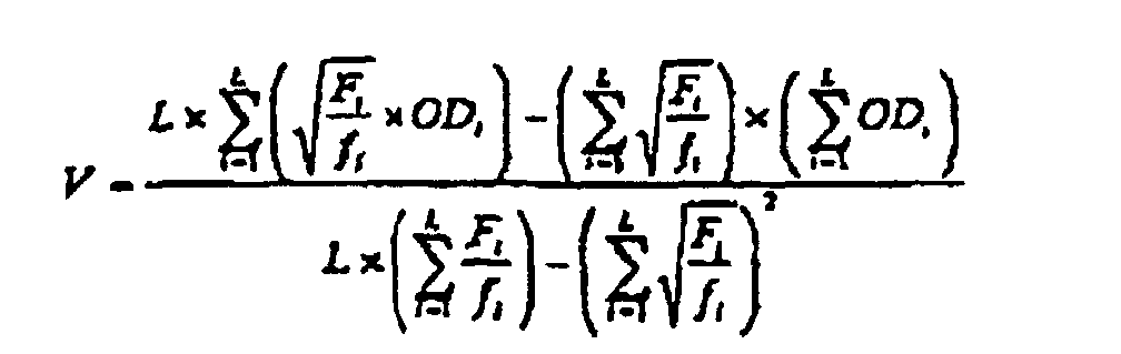
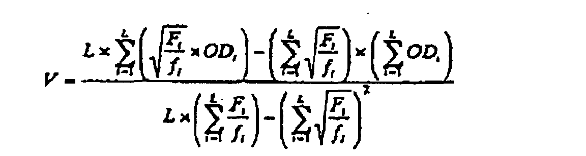
- V and W each represent constants which depend on state of perforations of a stencil sheet, quality of a printing sheet, and viscosity and a coloring material of an ink. They can be determined from the relation between F/f and OD obtained in trial printing, by a statistical method such as the least-squares method.
- a printing density (OD) of a particular portion of a print can be predicted based on a combination of a pressing force F and a rotation speed f of the drum.
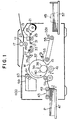
- FIG. 1 shows a preferred embodiment of the stencil printing device according to the present invention, which is equipped with a plate making function.
- This stencil printing device comprises an original reading unit 11, a plate making unit 13, and a printing unit 15.
- the original reading unit 11 essentially consists of an image scanner, and comprises a line image sensor 17 for reading an original image of an original sheet conveyed in a secondary scanning direction, and an original sheet feeding roller 19.
- the original reading unit 11 is used for reading the image of the original, and may be used as a device for measuring a printing density of prints printed by the printing device itself.
- a reflection densitometer and the like may be separately provided as a device for measuring the printing density of the prints, so that measured values are input by keying or stored automatically.
- the plate making unit 13 comprises a stencil sheet roll unit 21, a thermal printing head 23 consisting of a plurality of dot-like heat generating elements arranged in a lateral row, master plate sheet feeding rollers 25 and 27, master plate sheet guide rollers 29, 31 and 33, and a master plate sheet cutter 35.
- the dot-like heat generating elements in the thermal printing head 23 are selectively and independently activated so that a desired thermal perforation may be carried out in a dot-matrix way in the master plate sheet M that is heat sensitive, as a plate making process, and the master plate sheet cutter 35 cuts the stencil master plate sheet M after the latter has been perforated.
- the printing unit 15 comprises a cylindrical printing drum 37 made of a perforated metal plate, a mesh structure or an otherwise ink permeable porous structure, an ink supplying unit 39 essentially consisting of a squeegee roller 38 and a doctor roller 40 disposed inside the printing drum 37, and a press roller 41.
- the outer circumferential surface of the printing drum 37 is adapted to be wound with a stencil master plate sheet M that has been processed and cut into a master plate.
- a paper feeding unit 43 On one side of the printing unit 15 is provided a paper feeding unit 43, and on the other side of the printing unit 15 is provided a paper ejecting unit 45.
- the paper feeding unit 43 comprises a paper feeding table 47 on which a stack of printing paper P is placed, pick up rollers 49 for picking up the printing paper P on the paper feeding table 47 sheet by sheet, and timing rollers 51 for delivering the printing paper P to the nip between the printing drum 37 and the press roller 41.
- the paper ejecting unit 45 comprises a peeling claw 53 for removing the printing paper from the printing drum 37, an ejected paper feeding belt 55, and an ejected paper table 57 for stacking up the printed printing paper. Furthermore, as shown in FIG. 1, a printing density sensor 1331 may be provided as a device for measuring the printing density of the prints printed by the printing device itself.
- a master plate ejecting unit 63 comprising master plate ejecting rollers 61 for peeling off the used stencil master plate sheet M from the printing drum 37 and delivering it into an ejected master plate box 59.
- printing ink of a desired color is supplied by the ink supplying unit 39 into the inner surface of the printing drum 37 while the printing drum 37 is rotated counterclockwise in the drawing around its central axial line by rotative drive means not shown in the drawings.
- Printing paper P is delivered to the nip between the press roller 41 and the printing drum 37 after being fed by the paper feed timing rollers 51 from the left to right in synchronism with the rotation of the printing drum 37 at an appropriate timing.
- the printing paper P is thus pressed upon the printing drum 37 by the press roller 41 onto the stencil master plate sheet M mounted on the outer circumferential surface of the printing drum, and a stencil printing is carried out on the printing paper P by using the printing ink of the desired color.
- FIG. 2 shows the drive unit for the press roller 41.
- the press roller 41 is supported by a bracket 65, extending in the axial direction of the printing drum 37, so as to be rotatable around its central axial line, and the bracket 65 is in turn fixedly secured to a press shaft 69 rotatably supported by a fixed member or frame not show in the drawings.
- the press roller 41 is vertically swingable around the press shaft 69, and can move between a retracted position spaced from the outer circumferential surface of the printing drum 37 and a position for pressing action engaged upon the outer circumferential surface of the printing drum 37.
- the press shaft 69 carries a press drive lever 71 fixedly mounted thereon, and rotatably supports a press drive plate 73.
- a hook member 77 is pivotally supported on the press drive plate 73 by means of a pivot shaft 75, and selectively engages with the press drive lever 71 by being rotatively driven by a solenoid 79 mounted on the press drive plate 73 for selectively engaging the press drive lever 71 with the press drive plate 73.
- first link member 83 An end of a first link member 83 is pivotally connected to an end of the press drive plate 73 by means of a pivot shaft 81.
- the first link member 83 is provided with a pair of slots 85 extending in the same direction, and these slots 85 receive pins 89 of a second link member 87.
- the first link member 83 and the second link member 87 are connected with each other so as to be relatively moveable in the lengthwise direction or vertically as seen in FIG. 2 within the range permitted by the slots 85.
- the lower end of the first link member 83 is provided with a bent flange piece 91 through which an adjust screw 93 is passed so as to be adjustable in the direction of the reciprocating movement of the first link member 83.
- the adjust screw 93 threads with a nut member 99 provided with outer teeth 97 in the manner of a spur gear and supported by the lower surface of the bent flange piece 91 by way of a collar 95 against a thrust force, and the upper end of the adjust screw 93 is connected to an end of a tensile coil spring 101.
- the adjust screw 93 is thus prevented from rotating by being engaged by the one end of the tensile coil spring 101, and is axially displaced with respect to the first link member 83 by the rotation of the nut member 99.
- the tensile coil spring 101 is engaged by one of the pins 89 at its other end, thus urging the first link member 83 upwards relative to the second link member 87, or in other words urging the press drive plate 73 in counter clockwise direction in FIG. 2 around the press shaft 69 to press the press roller 41 onto the outer circumferential surface of the printing drum 37.
- the second link member 87 is pivotally connected to a free end portion of a cam lever 105 by a pivot shaft 103.
- the cam lever 105 is rotatably supported on a frame not shown in the drawings by a support shaft 107.
- the cam lever 105 rotatably supports a cam follower roller 109 in a freely rotatable manner.
- the cam follower roller 109 engages with a press cam 113 mounted on a main shaft 111.
- a frame not shown in the drawings rotatably supports the main shaft 111.
- the press cam 113 rotates in synchronism with the printing drum 37, and is provided with a cam profile which moves the press roller 41 to its retracted position to avoid the interference between the press roller 41 and a clamp unit when the clamp unit is located in a position corresponding to the press roller 41.
- the clamp unit is not shown in the drawings, but disposed on an outer circumferential surface of the printing drum 37 to clamp an end of a stencil master plate sheet wound around the drum as in conventional stencil printing machines.
- the bent flange piece 91 carries an electric motor 1302 for adjusting the pressing force, and a drive gear 119 is fixedly secured to an output shaft 117 of the electric motor 1302.
- the drive gear 119 meshes with the outer teeth 97 of the nut member 99 for transmitting the rotation of the output shaft 117 of the electric motor 1302 for adjusting the pressing force.
- the rotation of the printing drum 37 causes the press cam 113 to rotate in the clockwise direction as seen in FIG. 2, and this rotation in turn causes a substantially vertical reciprocating movement of the second link member 87 which is transmitted to the first link member 83 via the tensile coil spring 101.
- the reciprocating movement of the first link member 83 causes the press drive plate 73 to angularly reciprocate around the press shaft 69, and because the hook member 77 is moved into engagement with the press drive lever 71 by the solenoid 79, the reciprocating movement of the press drive plate 73 is transmitted to the press shaft 69.
- the reciprocating angular movement of the press shaft 69 causes the press roller 41 to vertically swing around the press shaft 69 so that the press roller 41 may move between the retracted position spaced from the outer circumferential surface of the printing drum 37 and the pressing position where the roller 41 is pressed against the outer circumferential surface of the printing drum 37.
- the movement of the press roller 41 to the pressing position is effected by the second link member 87 being lifted, by this movement being transmitted to the first link member 83 through tensioning of the tensile coil spring 101, and by the press drive plate 73 being rotated in counter clockwise direction as seen in FIG. 2 around the press shaft 69 of the press drive plate 73.
- the press roller 41 is pressed against the outer circumferential surface of the printing drum 37 with the printing paper P interposed therebetween, thereby restricting any further rotation of the press drive plate 73 in counter clockwise direction as seen in FIG. 2 around the press shaft 69.
- the second link member 87 is further lifted until the second link member 87 moves relative to the first link member 83 and the tensile coil spring 101 is extended.
- the spring force of the stretched tensile coil spring 101 presses the press roller 41 on the outer circumferential surface of the printing drum 37 with printing paper P interposed therebetween, and the magnitude of the pressing force is determined by this spring force.
- the electric motor 1302 for the adjustment of the pressing force is activated, and the drive gear 119 is rotated.
- the rotation of the driver gear 119 is transmitted to the nut member 99, and the rotation of the nut member 99 causes the adjust screw 93 to move axially relative to the first link member 83, thereby changing the position of the adjust screw 93 relative to the first link member 83.
- the point of engagement between the tensile coil spring 101 and the adjust screw 93 moves axially relative to the first link member 83, and this displacement causes a change in the length of the tensile coil spring 101, and hence its preset spring force.
- the change in the preset force of the tensile coil spring 101 changes the pressure, that is, the pressing force by which the press roller 41 is pressed against the outer circumferential surface of the printing drum 37 as described above. It can be clearly understood that such a means as a solenoid, an air cylinder and a hydraulic pressure is also usable as a means for generating the pressing force.
- the printing drum 37 for use in the present embodiment is supported on a movable support frame as a unit together with an ink bottle accommodating printing ink therein, an ink delivery pump for drawing printing ink from the ink bottle and delivering it to the supplying unit 39, and a drive motor for the ink delivery pump.
- the entire unit can be replaceably loaded into the body of the stencil printing device.
- FIG. 3 shows the control unit which totally controls the operation of the stencil printing device inclusive of the operation control of the electric motor 1302 for the adjustment of the pressing force, in which the only parts of the stencil printing device that are related to the present invention are illustrated for the simplification of description.
- the control unit of FIG. 3 comprises a CPU 1201 consisting of a micro processor or something like that, a ROM 1202 storing programs for controlling the operation of various units in the stencil printing device, and a RAM 1203 storing, as required, results of arithmetic operations carried out by the micro processor and various input information.
- the stencil printing device comprises an operation panel 1100 equipped with a ten key 1101 for setting the desired number of copies, a printing speed set up key 1102, a printing density set up key 1103, a predicting mode set up key 1104, a printing start key 1105, and a display 1106, where the CPU 1201 receives, for instance, information on the desired number of copies set up on the ten key 1101; information on printing speed set up by the printing speed set up key 1102, that is, information on rotation speed of the printing drum; information on a relative printing density set by the printing density set up key 1103, that is, information on a value of ⁇ (F/f); information on the starting of predicting mode set by the predicting mode set up key 1104; and information commanding a start of printing set by the printing start key 1105.
- the CPU 1201 controls the drive motor 1312 for the printing drum via the motor drive circuit 1311 for driving the printing drum, and receives information on an actual rotation speed of the printing drum fed back from a rotation speed sensor 1321, for example, a rotary encoder.
- the CPU 1201 receives the information on the printing density of the prints printed by the printing device itself, which is measured by the printing density sensor 1331 provided to, for example, the original reading unit 11 or the paper ejecting unit 45, etc.
- the CPU 1201 collects a set of information consisting of a set value of ⁇ (F/f), a printing density of a print, and positional information on a position at which the printing density was measured on the print; obtains an equation which relates ⁇ (F/f) to the printing density by a statistical processing method based on the plurality of the information sets; and predicts a printing density at a value of ⁇ (F/f) desired by a user, or a printing condition at a printing density desired by a user.
- the CPU 1201 also determines a pressing force in performing printing based on the set value of ⁇ (F/f) and the set rotation speed of the printing drum, either by calculation or with reference to a table in which previously-calculated results are stored.
- the CPU 1201 also determines an operation quantity of the motor 1302 for adjustment to a targeted pressing force, and outputs the operation quantity to the motor drive circuit 1301. Furthermore, when rotation speed of the printing drum is accelerated or decelerated during printing, the motor 1302 for the adjustment of the pressing force is controlled to increase or decrease the pressing force to maintain the previously set value of ⁇ (F/f) to be substantially constant.
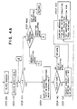
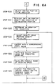
- FIG. 4 A control flow for predicting operation of printing density and calculation operation of proper printing conditions for the stencil printing device according to the present invention is shown in FIG. 4, FIG. 5, FIG 6, and FIG. 7.
- the program of the control flow may be recorded in a recording medium other than the aforementioned ROM 1202.
- step 100 plate-making is carried out at first (step 100). Thereafter, information on the densities of prints and their printing conditions stored previously is deleted from RAM 1203, and the counter L that indicates the number of the stored information is reset to indicate 0 (step 110). Then, the value of L is judged as to whether it is less than 2 or not (step 120), and if L is less than 2, the user is prompted that information necessary for prediction is missing (step 130). Then, the user decides whether he collects pieces of information sufficient for prediction so as to continue the predicting mode, or terminate the predicting mode (step 140).
- a desired printing density is set by the printing density set up key 1103 (step 150).
- the printing density may be set by direct input of a value of ⁇ (F/f) by the ten key 1101, or may be selected by keys or a volume dial from several "dense” to "pale” levels so that the user can easily set the value.
- a method of indirectly setting the value of ⁇ (F/f) by entering or selecting a numeral from a range of 1 to 20 using keys or a volume dial is described below.
- the value of ⁇ (F/f) is variable and controllable in a range of from 0.289 to 0.816.
- the printing density is variable and controllable in a range the minimum printing density of which is a printing density obtained in a printing condition that yields 0.289 as a value of ⁇ (F/f), and the maximum printing density of which is a printing density obtained in a printing condition that yields 0.816 as a value of ⁇ (F/f).
- a condition for the least dense printing can be set by entering numeral 1 as a density index on the operation panel 1100, which is then calculated into 0.289 as the value of ⁇ (F/f).
- numeral 1 as a density index on the operation panel 1100
- a larger numeral n is input. If the maximum printing density is needed, a value of 20 as a density index is entered.
- the possible range for setting the printing density corresponds to the entire range of controllable value of ⁇ (F/f), but it may be limited to a range that is most frequently used.
- the increment of ⁇ (F/f) per density index may be constant, or may be partially narrowed or broadened.
- a sensor may be provided to detect such variations in these factors, so that the function that converts the density index into the value of ⁇ (F/f) or a coefficient thereof can be modified according to the variations to make it easier for the user to set a printing density.
- a density index is input by operating the printing density set up key 1103 on the operation panel 1100.
- the density index input here be n c (step 150).
- the CPU 1201 converts the density index n c into a value of ⁇ (F/f) by calculation according to the following equation or with reference to a table in which previously calculated results are stored.
- CPU 1201 confirms whether a trial printing has already been done under the same condition as one which gives the value of ⁇ (F/f) obtained by conversion in step 160 (step 170). If a trial printing is already performed under the same condition (step 180), this is displayed on the display 1106 (step 410), and the user is asked to set a different printing condition (step 150).
- the CPU 1201 reads out, from the ROM 1202, the maximum and minimum values F max and F min of the pressing force controllable by the printer, as well as the maximum and minimum values f max and f min of the rotation speed of the printing drum controllable by the printer. Then, values of f a and f b are determined by calculation in accordance with the equation below, or with reference to a table in which previously calculated results are stored.
- f a F min / C 2
- f b F max / C 2
- f a is set as the minimum value of the controllable rotation speed of the printing drum, and if f min is not greater than f a , f a is set as the minimum value.
- f max is not greater than f b
- f max is set as the maximum value
- f b is set as the maximum value of the controllable rotation speed of the printing drum. Then, the maximum value and the minimum value thus determined are displayed on the operation panel 1100 (step 190).
- the user inputs information on rotation speed of the printing drum by selecting a value from the range of the rotation speed displayed on the panel using the printing speed set up key 1102, and the CPU 1201 stores the input value in the RAM 1203.
- the number of copies Q to be produced in trial printing is set by use of the ten key 1101 on the operation panel 1100, and the copy number information is stored in the RAM 1203 (step 210). It is then monitored if the printing start key provided on the operation panel 1100 is keyed in or not; that is, it is monitored whether printing is to be started or not (step 220).
- the printing drum starts to be driven to the set rotation speed. Whether rotation of the printing drum is accelerated to the set rotation speed from stopped state or from rotated state during printing, an abrupt change in speed is unfavorable, and a moderate change in printing speed is preferred. On the other hand, since printing density depends on rotation speed of the printing drum, printing density should be adjusted by the pressing force if the printing speed is changed.
- the present embodiment employs, as described below, a method in which a compensation amount of pressing force is properly determined in response to variation in monitored rotation speed of the printing drum. However, the method for compensation may be such that determines a rotation speed of the printing drum in response to variation in the pressing force being monitored.
- the CPU 1201 collects information on rotation speed of the printing drum from a rotation speed sensor 1321 such as a rotary encoder fitted to the printing drum or a motor for driving the printing drum (step 230).
- a rotation speed sensor 1321 such as a rotary encoder fitted to the printing drum or a motor for driving the printing drum
- the observed rotation speed of the printing drum be f t1 and a desired rotation speed of the printing drum stored in the RAM 1203 be f e .
- the CPU 1201 compares f t1 with f e , and if the difference between them is 30 rpm or more, a control signal is output to the motor drive circuit 1311 for accelerating or decelerating the printing drum by 30 rpm. When the difference is less than 30 rpm, a control signal is output to the motor drive circuit 1311 for driving the printing drum to match f t1 with f e (step 240).
- the CPU 1201 outputs an operation signal to the motor drive circuit 1301 for controlling the pressing force in such a manner that the calculated proper pressing force should be realized.
- the motor 1302 for adjustment of pressing force is driven in accordance with the thus output signal, and the nut member 99 is rotated so that the pressing force is set at a proper value while the tensioning of the tensile coil spring 101 is optimized (step 270).
- the value of counter N is incremented every time printing is executed on a sheet of printing paper, and the counter value is rewritten (step 280).
- the number of copies Q to be produced by trial printing is compared with the counter value N, and if N is smaller than Q, printing process is executed again while controlling the value of ⁇ (F/f), until the printing is stopped when N becomes a value equivalent to or larger than Q (step 290).
- step 300 After finishing the trial printing, it is confirmed that a satisfactory density is obtained on the print (step 300).
- the confirmation can be done either subjectively or objectively, i.e., by visual judgement or by measuring the optical density.
- the printing is executed to obtain the desired number of copies under a condition maintaining the value of ⁇ (F/f), i.e., the condition of trial printing.
- the print obtained in trial printing is set on the original reading unit 11 to acquire the information on a density of the print and a position where the density is measured on the print, (step 310). Otherwise, a printing density sensor 1331 may be provided at the paper ejecting portion to automatically acquire the density and positional information on the print during printing.
- the counter L which provides the number of density information is incremented by 1 and stored; thus, the information on the measured density of the print and the position thereof, the value of ⁇ (F/f) corresponding to the printing condition, and the value of the counter provided as an identification number to distinguish a set of information from others, are stored in the RAM 1203 as a set of information (step 320).
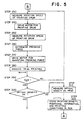
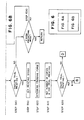
- a predicting mode can be selected by keying a predicting mode set up key 1104 provided on the operation panel 1100 (step 400). If the user desires to know a value of the printing density under a printing condition ⁇ (F/f) set by the printing density set up key 1103 and/or the printing speed set up key 1102 in advance, density predicting mode can be selected. Otherwise, if the user desires to execute printing by at a specific value of printing density, a condition calculating mode can be selected. If the user does not desire to use the predicting mode, the selection is ended by simply hitting a return key.
- the density predicting mode is selected, as shown in FIG. 6, the information on positions at which printing density has been measured and stored is displayed on the display 1106, and the user selects a position at which he desires to predict a printing density (step 500).
- the number of information sets each consisting of a printing density at the selected position and its printing condition, i.e., a value of ⁇ (F/f) stored in the RAM 1201, is L. Then, the information sets are retrieved from the RAM 1201 (step 510). Then, an equation for predicting a printing density is determined from the thus retrieved information sets in accordance with the following equations (step 520):
- a printing condition under which an optical density is predicted, is set.
- a pressing force F at which a printing sheet is pressed to the drum and a rotation speed f of the drum may be set by keying directly; however, as described above, the user may indirectly set the value of ⁇ (F/f) by using the density index n with operation of the printing density set up key 1103 (step 530).
- the CPU 1201 then converts the thus set density index into a value of ⁇ (F/f) (step 540). Let the value of ⁇ (F/f) after conversion be G.
- the CPU 1201 predicts a printing density by substituting G for the value of ⁇ (F/f) in the above prediction equation (step 550).
- the CPU 1201 then reads out, from the ROM 1202, the maximum and minimum values F max and F min of the pressing force controllable by the printer, as well as the maximum and minimum values f max and f min of the rotation speed of the printing drum controllable by the printer. Then, values of f a and f b are determined by calculation in accordance with the equation below, or with reference to a table in which previously calculated results are stored.
- f a F min / G 2
- f b F max / G 2
- the user judges whether the predicted printing density matches with the desired one (step 580), and, if necessary, the printing conditions are set again (step 630). If the deviation from the desired range is too large to correct by simply changing the printing condition, plate-making is newly carried out. If the predicted printing density matches with the desired one, trial printing is executed for confirmation.
- a rotation speed of the drum is selected from the displayed selectable range of rotation speed by keying the printing speed set up key 1102, and the information is input and stored in the RAM 1203 by the CPU 1201. Let the printing speed thus set be f g (step 590).
- the CPU 1201 determines a proper pressing force fg by calculation in accordance with the equation below, or with reference to a table in which previously calculated results are stored (step 600).
- F g f g ⁇ G 2
- the number of copies Q to be produced by trial printing is set by use of the ten key 1101 on the operation panel 1100, and the copy number information is stored in the RAM 1203 (step 610). It is then monitored if the print start key provided on the operation panel 1100 is keyed in or not; that is, it is monitored whether printing is to be started or not (step 620).
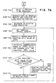
- the printing condition calculating mode is, as shown in FIG. 7, a method for predicting a proper printing condition under which a printed image of a desired optical density is obtained. For instance, in case of superposing inks of different colors to obtain an image with a desired color hue and lightness, printing must be executed in each color at a specific optical density.
- the CPU 1201 displays, on the display 1106, the information on positions at which optical densities of prints have been measured and stored.
- the user selects a desired position at which an optical density is to be set (step 700).
- the number of information sets each consisting of a printing density OD and its printing condition, i.e., the value of ⁇ (F/f) stored in the RAM 1201, is L.
- the information sets are retrieved from the RAM 1201 (step 710).
- the targeted printing density is then set (step 730). Let the printing density thus set be OD h .
- the CPU 1201 then reads out, from the ROM 1202, the maximum and minimum values f max and f min of the rotation speed of the printing drum controllable by the printer, as well as the maximum and minimum values F max and F min of the pressing force controllable by the printer. Then, the range of value ⁇ (F/f) controllable by the printer is calculated in accordance with the following formula (step 750). Furthermore, it compares whether the value of ⁇ (F/f) predicted above as a proper printing condition is included in the controllable range or not (step 760). ⁇ ( F min / f max ) ⁇ H ⁇ ⁇ ( F max / f min )
- f a is set as the minimum value of the controllable rotation speed of the printing drum, and if f min is not greater than f a , f a is set as the minimum value.
- f max is not greater than f b
- f max is set as the maximum value
- f b is set as the maximum value of the controllable rotation speed of the printing drum.
- step 790 judges whether the predicted printing speed falls within the desired range or not (step 790), and if necessary, reconsiders the targeted printing density or conduct a new plate-making (step 850). If the predicted printing condition matches with a desired one, trial printing is executed for confirmation.
- a printing speed f h is set (step 800), and the CPU 1201 determines a proper pressing force F h by calculation in accordance with the equation below, or with reference to a table in which previously calculated results are stored (step 810).
- F h f h ⁇ H 2
- the number of copies Q to be produced in trial printing is set by use of the ten key 1101 on the operation panel 1100, and the CPU 1201 stores the copy number information in the RAM 1203 (step 820). It is then monitored if the print start key provided on the operation panel 1100 is keyed in or not; that is, it is monitored whether printing is to be started or not (step 830).
- printing density was approximated by a first order equation of ⁇ (F/f).
- other functions such as a polynomial and the like, may be used for the approximation. More specifically, the formula of Murray and Davis or of Yule and Nielsen concerning the reflection density of dot prints can be used as well.
- the pressing force is determined after the printing speed is set, when a combination of a printing speed and a pressing force that realizes a desired ⁇ (F/f) value is determined.
- a pressing force may be determined prior to the setting of a printing speed.
- Printing was performed using the above stencil printing device under printing conditions of two different levels of ⁇ (F/f).
- Printing was executed under the printing condition of the third level, and the observed reflection density was compared with the predicted value. Then, the observed reflection density was added as an additional data to the ones previously obtained under the two different levels to make a prediction of a printing density under a printing condition of the fourth level.
- the predicted reflection density was compared with a reflection density observed in actual printing under the printing condition of the fourth level.
- the observed reflection density obtained under the printing condition of the fourth level was added as an additional data to the previous three data obtained under different three levels, and prediction was made accordingly on the printing density to be obtained under a printing condition of a fifth level value of ⁇ (F/f).
- the predicted value was compared with a reflection density observed in actual printing under the printing condition of the fifth level.
- perforation rate herein means a percentage of the perforated holes in a master plate for stencil printing with respect to the maximum resolution of a plate-making device; for instance, the perforation rate is 100 % if 400 holes are perforated per 1 inch by using a plate making device having a resolution of 400 dpi, and is 50 % if 200 holes are perforated by using the same plate making device.
- a commercially available stencil printing ink (GR ink, black, manufactured by Riso Kagaku Corporation) was used as a printing ink, and wood-free paper (Riso A3-size printing paper manufactured by Riso Kagaku Corporation) was used as printing paper.
- Rotation speed of the printing drum was measured in unit of rpm by using a rotary encoder.
- Pressing force of the press roller was measured in unit of kg ⁇ f by a load cell which was pressed by the entire press roller while the press roller is under pressing operation by the drive unit.
- the printing density can be predicted under desired printing conditions on the basis of printing density values that have been obtained under printing conditions of two or more different levels of ⁇ (F/f). It is also found that the observed reflection densities fall within a range of ⁇ 10 % of the predicted reflection density.
- a printing density and a printing condition for stencil printing can be predicted without much trial printing.
- the present invention avoids waste of printing paper, and reduces printing cost and consumption of resources.
Landscapes
- Inking, Control Or Cleaning Of Printing Machines (AREA)
- Force Measurement Appropriate To Specific Purposes (AREA)
- Printing Methods (AREA)
Claims (18)
- Verfahren zum Voraussagen einer Druckdichte beim Schablonendruck, bei dem eine perforierte Schablone um eine Umfangsfläche einer Drucktrommel gelegt wird, der eine Druckfarbe zugeführt wird, und die Druckfarbe von der Drucktrommel auf eine Druckbogen über die perforierte Schablone dadurch übertragen wird, dass der Druckbogen und die Drucktrommel gegeneinander gedrückt werden, während die Trommel gedreht wird, welches Verfahren(a) einen ersten Schritt, in dem die Druckdichten auf wenigstens zwei Drucken an entsprechenden bedruckten Bereichen gemessen werden, wobei die Drucke unter verschiedenen Verhältnissen F/f erhalten wurden, wobei F die Druckkraft, mit der Druckbogen an die Trommel gedrückt wird, und f die Drehgeschwindigkeit der Trommel bezeichnen,(b) einen zweiten Schritt, in dem statistisch alle im ersten Schritt gemessenen Druckdichten verarbeitet werden, um eine Funktion der Druckdichte in Abhängigkeit vom F/f-Wert zu erhalten, und(c) einen dritten Schritt umfasst, in dem die Druckdichte bei einer gewünschten Druckkraft und bei einer gewünschten Drehgeschwindigkeit auf der Grundlage der im zweiten Schritt erhalten Funktion berechnet wird.
- Verfahren zum Voraussagen einer Druckdichte nach Anspruch 1, bei dem die im zweiten Schritt erhaltene Funktion gegeben ist durch:
- Verfahren zum Voraussagen der Druckdichte nach Anspruch 2, bei dem V und W nach dem Verfahren der kleinsten Quadrate gemäß der folgenden Gleichungen
 berechnet werden.
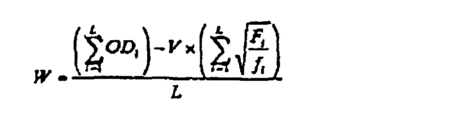
- Verfahren zum Berechnen einer Druckbedingung beim Schablonendruck, bei dem einen perforierte Schablone um die Umfangsfläche einer Drucktrommel gelegt wird, der eine Druckfarbe zugeführt wird, und die Druckfarbe von der Drucktrommel über die perforierte Schablone auf einen Druckbogen dadurch übertragen wird, dass der Druckbogen und die Drucktrommel gegeneinander gedrückt werden, während die Trommel gedreht wird, welches Verfahren(a) einen ersten Schritt, in dem die Druckdichten auf wenigstens zwei Drucken an entsprechenden bedruckten Bereichen gemessen werden, welche Drucke unter verschiedenen Verhältnissen F/f erhalten wurden, wobei F die Druckkraft bezeichnet, mit der der Druckbogen an die Trommel gedrückt wird, und f die Drehgeschwindigkeit der Trommel ist,(b) einen zweiten Schritt, in dem statistisch die im ersten Schritt gemessenen Druckdichten verarbeitet werden, um eine Funktion der Druckdichte in Abhängigkeit vom F/f-Wert zu erhalten, und(c) einen dritten Schritt umfasst, in dem die Kombination aus einer Druckkraft und einer Drehgeschwindigkeit bei einer gewünschten Druckdichte auf der Grundlage der im zweiten Schritt erhaltenen Funktion berechnet wird.
- Verfahren zum Berechnen einer Druckbedingung nach Anspruch 4, bei dem die im zweiten Schritt erhaltene Funktion gegeben ist durch:
- Verfahren zum Berechnen einer Druckbedingung nach Anspruch 5, bei dem V und W nach dem Verfahren der kleinsten Quadrate gemäß der folgenden Gleichungen
 berechnet werden.
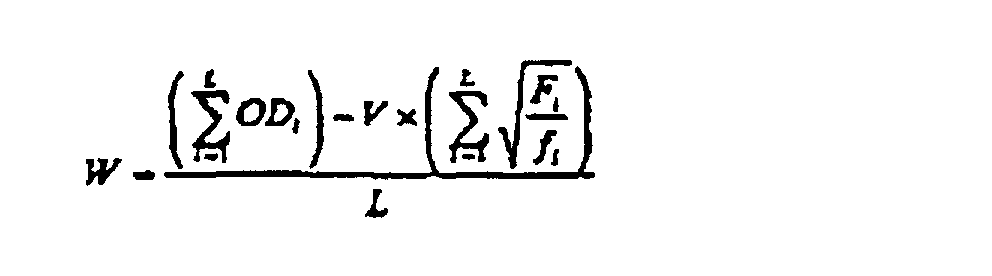
- Vorrichtung zum Voraussagen einer Druckdichte zur Verwendung beim Schablonendruck, beim dem eine perforierte Schablone um die Umfangsfläche einer Drucktrommel gelegt wird, der eine Druckfarbe zugeführt wird, und die Druckfarbe von der Drucktrommel über die Schablone auf einen Druckbogen dadurch übertragen wird, dass der Druckbogen und die Drucktrommel gegeneinander gedrückt werden, während die Trommel gedreht wird, welche Vorrichtung(a) eine erste Einrichtung zum Messung der Druckdichten auf wenigstens zwei Drucken an entsprechenden bedruckten Bereichen, welche Drucke unter verschiedenen Verhältnissen F/f erhalten wurden, wobei F die Druckkraft ist, mit der der Druckbogen an die Trommel gedrückt wird, und f die Drehgeschwindigkeit der Trommel bezeichnet,(b) eine zweite Einrichtung zum statistischen Verarbeiten der in der ersten Einrichtung gemessenen Druckdichten, um eine Funktion der Druckdichte in Abhängigkeit vom F/f-Wert zu erhalten, und(c) eine dritte Einrichtung zum Berechnen der Druckdichte bei einer gewünschten Druckkraft und einer gewünschten Drehgeschwindigkeit auf der Grundlage der in der zweiten Einrichtung erhalten Funktion umfasst.
- Vorrichtung zum Voraussagen einer Druckdichte nach Anspruch 7, bei der die in der zweiten Einrichtung erhaltene Funktion gegeben ist als:
- Vorrichtung zum Voraussagen der Druckdichte nach Anspruch 8, bei der V und W auf der Grundlage des Verfahrens der kleinsten Quadrate gemäß der folgenden Gleichungen
 berechnet werden.
- Vorrichtung zum Berechnen einer Druckbedingung zur Verwendung beim Schablonendruck, bei dem einen perforierte Schablone um die Umfangsfläche einer Drucktrommel gelegt wird, der eine Druckfarbe zugeführt wird, und die Druckfarbe von der Drucktrommel über die perforierte Schablone auf einen Druckbogen dadurch übertragen wird, dass der Druckbogen und die Drucktrommel gegeneinander gedrückt werden, während die Trommel gedreht wird, welche Vorrichtung(a) einen erste Einrichtung zum Messen der Druckdichten auf wenigstens zwei Drucken an entsprechenden bedruckten Bereichen, welche Drucke unter verschiedenen Verhältnissen F/f erhalten wurden, wobei F die Druckkraft bezeichnet, mit der der Druckbogen an die Trommel gedrückt wird, und f die Drehgeschwindigkeit der Trommel ist,(b) eine zweite Einrichtung zum statistischen Verarbeiten der in der ersten Einrichtung gemessenen Druckdichten, um eine Funktion der Druckdichte in Abhängigkeit vom F/f-Wert zu erhalten, und(c) eine dritte Einrichtung zum Berechnen der Kombination aus einer Druckkraft und einer Drehgeschwindigkeit bei einer gewünschten Druckdichte auf der Grundlage der im zweiten Schritt erhaltenen Funktion umfasst.
- Vorrichtung zum Berechnen einer Druckbedingung nach Anspruch 10, bei der die in der zweite Einrichtung erhaltene Funktion gegeben ist durch:
- Vorrichtung zum Berechnen einer Druckbedingung nach Anspruch 11, bei der V und W nach dem Verfahren der kleinsten Quadrate gemäß der folgenden Gleichungen
 berechnet werden.
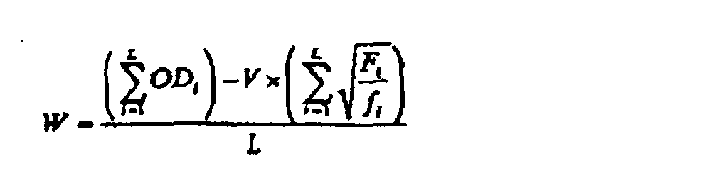
- Computerprogrammspeicherträger, der ein Programm zum Voraussagen einer Druckdichte für einen Schablonendruck enthält, bei dem einen perforierte Schablone um die Umfangsfläche einer Drucktrommel gelegt wird, der eine Druckfarbe zugeführt wird, und die Druckfarbe von der Drucktrommel über die perforierte Schablone auf einen Druckbogen dadurch übertragen wird, dass der Druckbogen und die Drucktrommel gegeneinander gedrückt werden, während die Trommel gedreht wird, welches Programm die folgenden Schritte umfasst:(a) Messen der Druckdichten auf wenigstens zwei Drucken an entsprechenden bedruckten Bereichen, welche Drucke unter verschiedenen Verhältnissen F/f erhalten wurden, wobei F die Druckkraft bezeichnet, mit der der Druckbogen gegen die Trommel gedrückt, wird und f die Drehgeschwindigkeit der Trommel ist,(b) statistisches Verarbeiten der im Schritt (a) gemessenen Druckdichten, um eine Funktion der Druckdichte in Abhängigkeit vom F/f-Wert zu erhalten, und(c) Berechnen der Druckdichte bei einer gewünschten Druckkraft und einer gewünschten Drehgeschwindigkeit auf der Grundlage der im Schritt (b) erhaltenen Funktion.
- Computerprogrammspeicherträger nach Anspruch 13, bei dem die im Schritt (b) erhaltene Funktion gegeben ist durch:
- Computerprogrammspeicherträger nach Anspruch 14, bei dem V und W nach dem Verfahren der kleinsten Quadrate gemäß der folgenden Gleichungen
 berechnet werden.
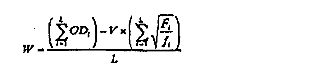
- Computerprogrammspeicherträger, der ein Programm zum Berechnen einer Druckbedingungen für einen Schablonendruck enthält, bei dem eine perforierte Schablone um die Umfangsfläche einer Drucktrommel gelegt wird, der eine Druckfarbe zugeführt wird, und die Druckfarbe von der Drucktrommel über die perforierte Schablone auf einen Druckbogen dadurch übertragen wird, dass der Druckbogen und die Drucktrommel aneinander gedrückt werden, während die Trommel gedreht wird, welches Programm die folgenden Schritte umfasst:(a) Messen der Druckdichten auf wenigstens zwei Drucken an entsprechenden bedruckten Bereichen, welche Drucke unter verschiedenen Verhältnissen F/f erhalten wurden, wobei F die Druckkraft bezeichnet, mit der der Druckbogen gegen die Trommel gedrückt wird, und f die Drehgeschwindigkeit der Trommel ist,(b) statistisches Verarbeiten der im Schritt (a) gemessenen Druckdichten, um eine Funktion der Druckdichte in Abhängigkeit vom F/f-Wert zu erhalten, und(c) Berechnen der Kombination aus einer Druckkraft und einer Drehgeschwindigkeit bei einer gewünschten Druckdichte auf der Grundlage der im Schritt (b) erhaltenen Funktion.
- Computerprogrammspeicherträger nach Anspruch 16, bei dem die im Schritt (b) erhaltene Funktion gegeben ist durch:.
- Computerprogrammspeicherträger nach Anspruch 17, bei dem V und W nach dem Verfahren der kleinsten Quadrate gemäß der folgenden Gleichungen
 berechnet werden.
Applications Claiming Priority (2)
| Application Number | Priority Date | Filing Date | Title |
|---|---|---|---|
| JP10026762A JPH11208089A (ja) | 1998-01-23 | 1998-01-23 | 孔版印刷濃度予測方法及び装置 |
| JP2676298 | 1998-01-23 |
Publications (3)
| Publication Number | Publication Date |
|---|---|
| EP0943448A2 EP0943448A2 (de) | 1999-09-22 |
| EP0943448A3 EP0943448A3 (de) | 1999-12-08 |
| EP0943448B1 true EP0943448B1 (de) | 2003-08-20 |
Family
ID=12202308
Family Applications (1)
| Application Number | Title | Priority Date | Filing Date |
|---|---|---|---|
| EP99300470A Expired - Lifetime EP0943448B1 (de) | 1998-01-23 | 1999-01-22 | Verfahren zum vorbestimmen der Druckdichte bei Schablonendruck |
Country Status (5)
| Country | Link |
|---|---|
| US (1) | US6263296B1 (de) |
| EP (1) | EP0943448B1 (de) |
| JP (1) | JPH11208089A (de) |
| CN (1) | CN1105653C (de) |
| DE (1) | DE69910473T2 (de) |
Families Citing this family (10)
| Publication number | Priority date | Publication date | Assignee | Title |
|---|---|---|---|---|
| JP2001080198A (ja) * | 1999-09-17 | 2001-03-27 | Riso Kagaku Corp | 孔版印刷装置 |
| JP2001315291A (ja) * | 2000-05-10 | 2001-11-13 | Tohoku Ricoh Co Ltd | 感熱孔版印刷装置 |
| JP3847263B2 (ja) * | 2003-02-12 | 2006-11-22 | 理想科学工業株式会社 | 孔版印刷方法および装置 |
| JP4584753B2 (ja) * | 2005-04-01 | 2010-11-24 | 東北リコー株式会社 | 印刷装置および紫外線照射装置 |
| US7859690B2 (en) * | 2005-12-15 | 2010-12-28 | Kabushiki Kaisha Toshiba | Image forming apparatus having proof copy function |
| JP5086538B2 (ja) * | 2005-12-26 | 2012-11-28 | 東北リコー株式会社 | 印刷装置 |
| JP5011554B2 (ja) * | 2007-05-15 | 2012-08-29 | 東北リコー株式会社 | 印刷装置 |
| EP2002977A3 (de) * | 2007-06-14 | 2010-04-07 | Komori Corporation | Einstellungsverfahren des Drucks für den Flüssigkeitstransfer und Vorrichtung einer rotierender Schablonendruckpresse-Flüssigkeitsbeschichtungsmaschine |
| JP5139876B2 (ja) * | 2008-04-25 | 2013-02-06 | キヤノン株式会社 | 画像形成装置及び画像形成方法 |
| CN110936743B (zh) * | 2019-11-29 | 2021-09-10 | 西安理工大学 | 一种基于图文信息的柔版印刷压力预测方法 |
Family Cites Families (13)
| Publication number | Priority date | Publication date | Assignee | Title |
|---|---|---|---|---|
| JPS6155880A (ja) * | 1984-08-28 | 1986-03-20 | 杉本練染株式会社 | 面発熱体 |
| JPS62127276A (ja) * | 1985-11-27 | 1987-06-09 | Riso Kagaku Corp | 孔版印刷装置 |
| US4791866A (en) * | 1986-09-09 | 1988-12-20 | Ricoh Co., Ltd. | Speed control method for printing press and printing press practicing the method |
| JP2932744B2 (ja) * | 1991-05-10 | 1999-08-09 | ブラザー工業株式会社 | スタンプ装置 |
| JPH04344283A (ja) | 1991-05-20 | 1992-11-30 | Omron Corp | 印刷装置 |
| JP2924294B2 (ja) * | 1991-06-06 | 1999-07-26 | ブラザー工業株式会社 | スタンプ装置 |
| JPH05286221A (ja) | 1992-04-13 | 1993-11-02 | Ricoh Co Ltd | 孔版印刷装置 |
| JP3190148B2 (ja) * | 1992-12-28 | 2001-07-23 | 理想科学工業株式会社 | 孔版印刷装置 |
| US5689297A (en) * | 1993-05-11 | 1997-11-18 | Tohoku Ricoh Co., Ltd. | Thermosensitive stencil printer capable of controlling image density |
| JP2746821B2 (ja) * | 1993-06-29 | 1998-05-06 | 理想科学工業株式会社 | 孔版印刷装置 |
| JP2593623B2 (ja) | 1993-06-29 | 1997-03-26 | 理想科学工業株式会社 | 孔版印刷装置 |
| US5476043A (en) * | 1993-09-16 | 1995-12-19 | Riso Kagaku Corporation | Method and device for post-processing a printed image in a printing device |
| JP3213457B2 (ja) | 1993-11-11 | 2001-10-02 | 理想科学工業株式会社 | 孔版印刷装置 |
-
1998
- 1998-01-23 JP JP10026762A patent/JPH11208089A/ja active Pending
-
1999
- 1999-01-22 EP EP99300470A patent/EP0943448B1/de not_active Expired - Lifetime
- 1999-01-22 US US09/235,555 patent/US6263296B1/en not_active Expired - Lifetime
- 1999-01-22 DE DE69910473T patent/DE69910473T2/de not_active Expired - Fee Related
- 1999-01-22 CN CN99101351A patent/CN1105653C/zh not_active Expired - Lifetime
Also Published As
| Publication number | Publication date |
|---|---|
| CN1105653C (zh) | 2003-04-16 |
| CN1223936A (zh) | 1999-07-28 |
| JPH11208089A (ja) | 1999-08-03 |
| EP0943448A2 (de) | 1999-09-22 |
| US6263296B1 (en) | 2001-07-17 |
| EP0943448A3 (de) | 1999-12-08 |
| DE69910473D1 (de) | 2003-09-25 |
| DE69910473T2 (de) | 2004-06-09 |
Similar Documents
| Publication | Publication Date | Title |
|---|---|---|
| JP3190148B2 (ja) | 孔版印刷装置 | |
| EP0943448B1 (de) | Verfahren zum vorbestimmen der Druckdichte bei Schablonendruck | |
| JP2828473B2 (ja) | 製版印刷装置 | |
| GB2208279A (en) | Printer device using a mimeograph | |
| US6295924B1 (en) | Stencil printing apparatus | |
| JP3073609B2 (ja) | オフセット印刷機の定常印刷時のインキ分布を調整する方法 | |
| EP0904949B1 (de) | Verfahren und Vorrichtung zum Regeln der Farbdichte in einer Schablonendruckmaschine | |
| JP2000000953A (ja) | オフセット印刷のための版を使用する印刷の際に湿し媒体を調量するための方法 | |
| JP2002086686A (ja) | 印刷制御装置、コンピュータ読み取り可能なプログラムを記録した記録媒体、印刷システム | |
| JP4380997B2 (ja) | 孔版印刷装置及び印刷方法 | |
| US20020007739A1 (en) | Stencil printing machine and stencil printing method | |
| JP3490371B2 (ja) | 孔版印刷装置及び孔版印刷方法 | |
| JPH11188962A (ja) | 孔版印刷濃度制御方法及び装置 | |
| JP3294364B2 (ja) | 製版機能付き孔版印刷装置 | |
| JP2002127580A (ja) | 孔版印刷装置 | |
| JP2002137530A (ja) | 孔版印刷方法及び装置 | |
| JP2002086885A (ja) | 印刷制御装置、コンピュータ読み取り可能なプログラムを記録した記録媒体、印刷システム | |
| JP2006062376A (ja) | 孔版印刷装置 | |
| JP2002361994A (ja) | 製版印刷装置 | |
| EP2383123B1 (de) | Vorrichtung für Schablonendruck die in Abhängigkeit von Stillstandszeit und Art der Schablone gesteuert wird | |
| JP3731018B2 (ja) | 孔版印刷装置 | |
| JP4764545B2 (ja) | 印刷装置 | |
| JP3827902B2 (ja) | 孔版印刷装置 | |
| JP5082618B2 (ja) | 押圧装置、印刷装置、シート押圧方法及び画像形成方法 | |
| JP4192507B2 (ja) | 統合印刷色調制御方法及び装置 |
Legal Events
| Date | Code | Title | Description |
|---|---|---|---|
| PUAI | Public reference made under article 153(3) epc to a published international application that has entered the european phase |
Free format text: ORIGINAL CODE: 0009012 |
|
| 17P | Request for examination filed |
Effective date: 19990208 |
|
| AK | Designated contracting states |
Kind code of ref document: A2 Designated state(s): DE FR GB |
|
| AX | Request for extension of the european patent |
Free format text: AL;LT;LV;MK;RO;SI |
|
| PUAL | Search report despatched |
Free format text: ORIGINAL CODE: 0009013 |
|
| AK | Designated contracting states |
Kind code of ref document: A3 Designated state(s): AT BE CH CY DE DK ES FI FR GB GR IE IT LI LU MC NL PT SE |
|
| AX | Request for extension of the european patent |
Free format text: AL;LT;LV;MK;RO;SI |
|
| AKX | Designation fees paid |
Free format text: DE FR GB |
|
| GRAH | Despatch of communication of intention to grant a patent |
Free format text: ORIGINAL CODE: EPIDOS IGRA |
|
| RIN1 | Information on inventor provided before grant (corrected) |
Inventor name: NAKAMURA, YASUO,RISO KAGAKU CORP.,R. & D. CENT |
|
| GRAH | Despatch of communication of intention to grant a patent |
Free format text: ORIGINAL CODE: EPIDOS IGRA |
|
| GRAA | (expected) grant |
Free format text: ORIGINAL CODE: 0009210 |
|
| AK | Designated contracting states |
Designated state(s): DE FR GB |
|
| REG | Reference to a national code |
Ref country code: GB Ref legal event code: FG4D |
|
| REF | Corresponds to: |
Ref document number: 69910473 Country of ref document: DE Date of ref document: 20030925 Kind code of ref document: P |
|
| ET | Fr: translation filed | ||
| PLBE | No opposition filed within time limit |
Free format text: ORIGINAL CODE: 0009261 |
|
| STAA | Information on the status of an ep patent application or granted ep patent |
Free format text: STATUS: NO OPPOSITION FILED WITHIN TIME LIMIT |
|
| 26N | No opposition filed |
Effective date: 20040524 |
|
| PGFP | Annual fee paid to national office [announced via postgrant information from national office to epo] |
Ref country code: DE Payment date: 20090115 Year of fee payment: 11 |
|
| PGFP | Annual fee paid to national office [announced via postgrant information from national office to epo] |
Ref country code: GB Payment date: 20090121 Year of fee payment: 11 |
|
| PGFP | Annual fee paid to national office [announced via postgrant information from national office to epo] |
Ref country code: FR Payment date: 20090113 Year of fee payment: 11 |
|
| GBPC | Gb: european patent ceased through non-payment of renewal fee |
Effective date: 20100122 |
|
| REG | Reference to a national code |
Ref country code: FR Ref legal event code: ST Effective date: 20100930 |
|
| PG25 | Lapsed in a contracting state [announced via postgrant information from national office to epo] |
Ref country code: FR Free format text: LAPSE BECAUSE OF NON-PAYMENT OF DUE FEES Effective date: 20100201 |
|
| PG25 | Lapsed in a contracting state [announced via postgrant information from national office to epo] |
Ref country code: DE Free format text: LAPSE BECAUSE OF NON-PAYMENT OF DUE FEES Effective date: 20100803 |
|
| PG25 | Lapsed in a contracting state [announced via postgrant information from national office to epo] |
Ref country code: GB Free format text: LAPSE BECAUSE OF NON-PAYMENT OF DUE FEES Effective date: 20100122 |