EP0942128B1 - Einrichtung für eine Einbruchmeldeanlage - Google Patents
Einrichtung für eine Einbruchmeldeanlage Download PDFInfo
- Publication number
- EP0942128B1 EP0942128B1 EP98123685A EP98123685A EP0942128B1 EP 0942128 B1 EP0942128 B1 EP 0942128B1 EP 98123685 A EP98123685 A EP 98123685A EP 98123685 A EP98123685 A EP 98123685A EP 0942128 B1 EP0942128 B1 EP 0942128B1
- Authority
- EP
- European Patent Office
- Prior art keywords
- door
- surface unit
- frame
- burglar alarm
- alarm system
- Prior art date
- Legal status (The legal status is an assumption and is not a legal conclusion. Google has not performed a legal analysis and makes no representation as to the accuracy of the status listed.)
- Expired - Lifetime
Links
Images

Classifications
-
- E—FIXED CONSTRUCTIONS
- E05—LOCKS; KEYS; WINDOW OR DOOR FITTINGS; SAFES
- E05B—LOCKS; ACCESSORIES THEREFOR; HANDCUFFS
- E05B47/00—Operating or controlling locks or other fastening devices by electric or magnetic means
- E05B47/02—Movement of the bolt by electromagnetic means; Adaptation of locks, latches, or parts thereof, for movement of the bolt by electromagnetic means
-
- E—FIXED CONSTRUCTIONS
- E05—LOCKS; KEYS; WINDOW OR DOOR FITTINGS; SAFES
- E05B—LOCKS; ACCESSORIES THEREFOR; HANDCUFFS
- E05B45/00—Alarm locks
- E05B45/06—Electric alarm locks
-
- E—FIXED CONSTRUCTIONS
- E05—LOCKS; KEYS; WINDOW OR DOOR FITTINGS; SAFES
- E05B—LOCKS; ACCESSORIES THEREFOR; HANDCUFFS
- E05B47/00—Operating or controlling locks or other fastening devices by electric or magnetic means
- E05B2047/0048—Circuits, feeding, monitoring
- E05B2047/0067—Monitoring
- E05B2047/0068—Door closed
-
- E—FIXED CONSTRUCTIONS
- E05—LOCKS; KEYS; WINDOW OR DOOR FITTINGS; SAFES
- E05B—LOCKS; ACCESSORIES THEREFOR; HANDCUFFS
- E05B63/00—Locks or fastenings with special structural characteristics
- E05B63/0052—Locks mounted on the "frame" cooperating with means on the "wing"
Definitions
- the invention is based on the type as indicated in the independent claim 1.
- This inevitability thus includes the protection against accidental access to the secure area. Without disarming the hazard alarm system according to VdS Class A, B and C, no-one may enter the safety area solely by operating the separate safety lock.
- the block lock is installed in addition to a locking lock in the door leaf, with a flexible cable from the door leaf to the frame must be laid.
- the locking mechanism of the block lock is released via the cable only if the associated burglar alarm system is ready to arm, and the closing of the burglar alarm system takes place when the block lock is closed with the aid of a key.
- the subject of the application with the features of claim 1 has the following advantage: Due to the design of the device according to the invention as Aufputzü with locking piece and the integration of both an electrically actuable blocking element and a component of a burglar alarm, in particular the switch or the magnet of a magnetic contact, the device is much less expensive mountable than known block locks.
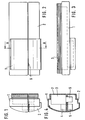
- the device shown in Figures 1 to 4 differs in design somewhat from the device according to Figures 5 to 7, the basic structure and the function are the same.
- the device consists of a Aufputzü 1 and a locking piece 2.
- the Aufputzü 1 contains an electrically actuated block element 3 and as part of a burglar alarm a magnetically actuated switch 4.
- a magnet 5 is housed in the locking piece 2.
- the block element 3 contains an electric drive for a latch 6, which engages in the latch piece 2 in the extended state (FIG. 4).
- the Aufputztechnik 1 has a mounting surface 7 which rests on the assembly on a door or frame each on this.
- FIGS 5 to 7 show possible arrangements of the device according to the invention in normal and escape doors.
- FIGS. 5 to 7 a frame shown in section is designated by 8.
- FIG. 5 shows a door 15, for example a glass door, which can be opened inwards or outwards.
- a door 15 for example a glass door, which can be opened inwards or outwards.
- To the left of the door shown is the outside area, on the right the interior area, in which the putty unit 1 is mounted with its mounting surface on the frame 8, while the locking piece 2 by means of a bracket 9 is attached to the door 15.
- the door 16 is an escape door.
- the outer area is thus right and the inner area to the left of the door 16.
- the locking piece 2 is attached via an angle 10 to the frame 8, while the Aufputzmaschine 1 is mounted on the door 16.
- a door 17 (normal door) is shown, which can be opened inwards.
- the interior is so right of this door, and accordingly, the device according to the invention is mounted on the right.
- the locking piece 2 is screwed directly onto the door 17, while the Aufputzü 1 with the interposition of shims 18, which are used for leveling, on the frame 8 is mounted.
- Such a shim plate 18 is also provided in Figure 6 between the Aufputzü 1 and the door 16 to compensate for the difference in level, which is caused by the angle 10.
- the shim is just as big as the mounting surface.
- FIGS. 5 to 7 thus show the various possible uses of the device according to the invention.
- the Aufputzü can be mounted on the inside of a frame and the locking piece on the inside of a door ( Figures 5 and 7). But it is also possible ( Figure 6) to mount the locking piece in the passage area of a frame, while the Aufputzü is attached to the inside of the door.
- the Aufputzü may have a lid with a lid contact, and the lid may be provided with means for sealing.
Description
- Die Erfindung geht von der Gattung aus, wie im unabhängigen Anspruch 1 angegeben.
- Bei einer Einbruchmeldeanlage ist diejenige Tür, die nach Verlassen des gesicherten Bereiches zuletzt geschlossen wird, dreifach gesichert, nämlich
- 1. wie andere Türen oder Fenster durch einen Einbruchmelder, beispielsweise einen Magnetkontakt, der beim Öffnen der Tür anspricht und bei scharfgeschalteter Einbruchmeldeanlage einen Alarm auslöst,
- 2.durch ein Sperrschloß, das gegen Gewaltanwendung sichert und einen Riegelkontakt aufweist, der den Schließzustand an die Zentrale der Einbruchmeldeanlage meldet, und
- 3.durch ein Blockschloß, das weniger gegen Gewaltanwendung schützen soll, sondern mehr eine Erinnerungsfunktion hat.
- Solange nämlich eine Einbruchmeldeanlage für einen gesicherten Bereich mittels einer Scharfschalteeinrichtung scharfgeschaltet ist, muß durch das Blockschloß sichergestellt sein, daß auch für eine befugte Person, die das Sperrschloß geöffnet hat, der Zutritt zum gesicherten Bereich noch verhindert bleibt (Zwangsläufigkeit), damit kein Fehlalarm ausgelöst werden kann.
- Diese Zwangsläufigkeit (Zutrittsverhinderung im scharfgeschalteten Zustand) beinhaltet also die Absicherung gegen versehentlichen Zugang in den gesicherten Bereich. Ohne Unscharfschaltung der Gefahrenmeldeanlage nach VdS-Klasse A, B und C darf niemand mit alleiniger Betätigung des gesonderten Sperrschlosses den Sicherheitsbereich betreten.
- Bei bestimmten Klassen von Einbruchmeldeanlagen muß die Scharfschaltung außerhalb des gesicherten Bereiches erfolgen, beispielsweise durch das Blockschloß; dieser Türverschluß kann dann nur nach einer elektrischen Freigabe von der Zentrale betätigt werden (Harald Fuhrmann, Gefahrenmeldesysteme, 1992, Hüthig, Heidelberg, Seiten 49, 50; vgl. auch DE-PS 1 261 222 und DE 36 39 111 C1). Im Handel ist ein Blockschloß erhältlich (Telenorma NBS 10), das als elektromechanische Scharfschalteeinrichtung zur Scharfschaltung einer Einbruchmeldezentrale verwendbar ist. Dieses Blockschloß wird in ein Türblatt eingebaut und verhindert durch seinen Schloßriegel ein unzulässiges Öffnen der Tür nach erfolgter Scharfschaltung und solange die Scharfschaltung weiterbesteht.
- Bei dem bekannten Blockschloß sind aber aufwendige Montagearbeiten im Türblatt erforderlich. Das Blockschloß wird zusätzlich zu einem Sperrschloß in das Türblatt eingebaut, wobei ein flexibles Kabel vom Türblatt zur Zarge verlegt werden muß. Über das Kabel wird der Schließmechanismus des Blockschlosses nur dann freigegeben, wenn die zugehörige Einbruchmeldeanlage scharfschaltebereit ist, und mit dem Schließen des Blockschlosses mit Hilfe eines Schlüssels erfolgt die Scharfschaltung der Einbruchmeldeanlage.
- Der Anmeldungsgegenstand mit den Merkmalen des Anspruches 1 hat folgenden Vorteil:
Durch die Gestaltung der erfindungsgemäßen Einrichtung als Aufputzeinheit mit Riegelstück und durch die Integration sowohl eines elektrisch betätigbaren Blockierungselementes als auch eines Bestandteiles eines Einbruchmelders, insbesondere des Schalters oder des Magneten eines Magnetkontaktes, ist die Einrichtung wesentlich unaufwendiger montierbar als bekannte Blockschlösser. - Vorteilhafte weiterbildungen sind in den abhängigen Ansprüchen angegeben, deren Merkmale auch, soweit sinnvoll, miteinander kombiniert werden können.
- Ein Ausführungsbeispiel der Erfindung ist in der Zeichnung dargestellt und im Folgenden näher erläutert. Dabei sind bei mehreren Figuren jeweils dieselben Bezugszeichen für im wesentlichen gleiche Teile verwendet. Schematisch ist gezeigt in
- Figur 1:
- eine Seitenansicht einer Einrichtung nach der Erfindung,
- Figur 2:
- eine Aufsicht der Einrichtung nach Figur 1,
- Figur 3:
- die Einrichtung nach Figur 2 von oben gesehen,
- Figur 4:
- einen Schnitt A-A durch die Einrichtung nach Figur 2,
- Figuren 5 bis 7:
- verschiedene Montagemöglichkeiten einer Einrichtung nach der Erfindung.
- Die in den Figuren 1 bis 4 gezeigte Einrichtung weicht im Design etwas von der Einrichtung nach den Figuren 5 bis 7 ab, der prinzipielle Aufbau und die Funktion sind jedoch gleich. Die Einrichtung besteht jeweils aus einer Aufputzeinheit 1 und einem Riegelstück 2. Die Aufputzeinheit 1 enthält ein elektrisch betätigbares Blockelement 3 und als Bestandteil eines Einbruchmelders einen magnetisch betätigbaren Schalter 4. Als Gegenstück zu diesem Schalter 4 ist in dem Riegelstück 2 ein Magnet 5 untergebracht. Das Blockelement 3 enthält einen elektrischen Antrieb für einen Riegel 6, der im ausgefahrenen Zustand (Figur 4) in das Riegelstück 2 eingreift. Weiterhin weist die Aufputzeinheit 1 eine Montagefläche 7 auf, die bei der Montage auf einer Tür oder Zarge jeweils auf dieser aufliegt.
- Die Figuren 5 bis 7 zeigen Anordnungsmöglichkeiten der erfindungsgemäßen Einrichtung bei Normal- und Fluchttüren.
- Der wesentliche Unterschied bei Türen ist die Anschlagsseite mit bevorzugter Öffnungsrichtung. Fluchttüren müssen immer nach außen aufgehen, Normaltüren immer in den Raum hinein. Damit ist zwangsläufig der gesicherte Raum festgelegt, in welchem sich die erfindungsgemäße Einrichtung befinden muß. In den Figuren 5 bis 7 ist eine im Schnitt dargestellte Zarge jeweils mit 8 bezeichnet.
- In Figur 5 ist eine Tür 15, beispielsweise eine Glastür, dargestellt, die sich nach innen oder außen öffnen läßt. Links von der gezeigten Tür ist der Außenbereich, rechts der Innenbereich, in welchem die Aufputzeinheit 1 mit ihrer Montagefläche an der Zarge 8 montiert ist, während das Riegelstück 2 mit Hilfe eines Bügels 9 an der Tür 15 befestigt ist.
- In Figur 6 handelt es sich bei der Tür 16 um eine Fluchttür. Der Außenbereich ist also rechts und der Innenbereich links von der Tür 16. Das Riegelstück 2 ist über einen Winkel 10 an der Zarge 8 befestigt, während die Aufputzeinheit 1 an der Tür 16 montiert ist.
- In Figur 7 ist eine Tür 17 (Normaltür) gezeigt, die sich nach innen öffnen läßt. Der Innenbereich ist also rechts von dieser Tür, und dementsprechend ist auch die Einrichtung nach der Erfindung rechts montiert.Das Riegelstück 2 ist unmittelbar auf die Tür 17 geschraubt, während die Aufputzeinheit 1 unter Zwischenschaltung von Unterlegplatten 18, die zum Niveauausgleich dienen, an der Zarge 8 montiert ist.
- Eine solche Unterlegplatte 18 ist auch in Figur 6 zwischen der Aufputzeinheit 1 und der Tür 16 vorgesehen, um den Niveauunterschied auszugleichen, der durch den Winkel 10 verursacht ist. Die Unterlegplatte ist gerade so groß wie die Montagefläche.
- Die Figuren 5 bis 7 zeigen also die verschiedenen Einsatzmöglichkeiten der erfindungsgemäßen Einrichtung. Die Aufputzeinheit kann an der Innenseite einer Zarge und das Riegelstück an der Innenseite einer Tür montiert sein (Figuren 5 und 7). Es ist aber auch möglich (Figur 6), das Riegelstück im Durchgangsbereich einer Zarge zu montieren, während die Aufputzeinheit an der Innenseite der Tür befestigt ist.
- Als Sabotageschutz kann die Aufputzeinheit einen Deckel mit Deckelkontakt aufweisen, und der Deckel kann mit Mitteln zur Verplombung versehen sein.
Claims (5)
- Einrichtung, die sich aus einer Aufputzeinheit (1), einem Riegelstück (2), einer Einbruchmeldeanlage, einer Tür (15, 16, 17) und deren Zarge (8) zusammensetzt, wobei die Aufputzeinheit (1) ein elektrisch betätigbares Blockierungselement (3) sowie einen Bestandteil eines Einbruchmelders, insbesondere den Schalter (4) oder den Magnet (5) eines Magnetkontaktes, enthält, wobei die Aufputzeinheit (1) und das Riegelstück (2) den Zutritt nach dem Öffnen eines an Tür (15, 16, 17) oder Zarge (8) vorgesehenen Sperrschlosses verwehren, solange die Einbruchmeldeanlage nicht unscharf geschaltet ist, wobei die Aufputzeinheit eine Montagefläche (7) aufweist, die bei der Montage auf der Tür (15, 16, 17) oder Zarge (8) jeweils auf dieser aufliegt, und wobei die Aufputzeinheit (1) einen Deckel mit Deckelkontakt aufweist.
- Einrichtung nach Anspruch 1, dadurch gekennzeichnet, daß das Riegelstück (2) einen weiteren Bestandteil (5) des Einbruchmelders (4, 5) enthält.
- Einrichtung nach Anspruch 1 oder 2, dadurch gekennzeichnet, daß der Deckel Mitteln aufweist, die eine Verplombung ermöglichen.
- Einrichtung nach einem der vorangehenden Ansprüche, dadurch gekennzeichnet, daß die Aufputzeinheit (1) einen Elektromotor als Antrieb für das Blockierungselement (3) aufweist.
- Einrichtung nach einem der vorangehenden Ansprüche, dadurch gekennzeichnet, daß zum Anlegen an die Montagefläche (7) wenigstens eine Unterlegplatte (18) vorgesehen ist, welche eine der Breitenabmessungen der Montagefläche (7) aufweist.
Applications Claiming Priority (2)
| Application Number | Priority Date | Filing Date | Title |
|---|---|---|---|
| DE19810623A DE19810623A1 (de) | 1998-03-12 | 1998-03-12 | Einrichtung für eine Einbruchmeldeanlage |
| DE19810623 | 1998-03-12 |
Publications (3)
| Publication Number | Publication Date |
|---|---|
| EP0942128A2 EP0942128A2 (de) | 1999-09-15 |
| EP0942128A3 EP0942128A3 (de) | 2002-02-06 |
| EP0942128B1 true EP0942128B1 (de) | 2006-05-17 |
Family
ID=7860554
Family Applications (1)
| Application Number | Title | Priority Date | Filing Date |
|---|---|---|---|
| EP98123685A Expired - Lifetime EP0942128B1 (de) | 1998-03-12 | 1998-12-11 | Einrichtung für eine Einbruchmeldeanlage |
Country Status (3)
| Country | Link |
|---|---|
| EP (1) | EP0942128B1 (de) |
| AT (1) | ATE326603T1 (de) |
| DE (2) | DE19810623A1 (de) |
Families Citing this family (2)
| Publication number | Priority date | Publication date | Assignee | Title |
|---|---|---|---|---|
| IT1395083B1 (it) * | 2008-11-12 | 2012-09-05 | Ceita Srl | Dipositivo di chiusura per porte a battente in particolare per porte di ascensori |
| ITME20120001A1 (it) * | 2012-01-11 | 2013-07-12 | Giuseppe Guido | La porta intelligente |
Citations (2)
| Publication number | Priority date | Publication date | Assignee | Title |
|---|---|---|---|---|
| EP0244652A1 (de) * | 1986-05-05 | 1987-11-11 | Fritz Fuss GmbH & Co. | Blockschloss |
| DE4344314A1 (de) * | 1993-12-23 | 1995-06-29 | Fuss Fritz Gmbh & Co | Einsteckschloß mit integrierter Blockschloßfunktion und Verfahren zum Scharfschalten einer Einbruchmeldeanlage mittels des Einsteckschlosses |
Family Cites Families (10)
| Publication number | Priority date | Publication date | Assignee | Title |
|---|---|---|---|---|
| US2322815A (en) * | 1941-06-21 | 1943-06-29 | Fred H Bock | Combined lock and alarm for windows and the like |
| DE1261222B (de) | 1964-04-25 | 1968-02-15 | Telefonbau | Elektrisches Schaltschloss |
| US3406386A (en) * | 1965-10-04 | 1968-10-15 | Gen Alarm Corp | Chain lock alarm |
| DE3639111C1 (en) | 1986-11-15 | 1988-02-11 | Merk Gmbh Telefonbau Fried | Stop-and-block lock |
| DE3707284A1 (de) * | 1987-03-06 | 1988-09-15 | Winkhaus Fa August | Elektronisches tuerschloss |
| WO1994005885A1 (en) * | 1992-08-28 | 1994-03-17 | Jens Herman Martin | Improvements in and relating to security |
| DE59406875D1 (de) * | 1993-03-25 | 1998-10-15 | Fankhauser Peter | Einrichtung zur sicherung von einen zugang verschliessenden mitteln |
| DE4318518C1 (de) * | 1993-06-03 | 1994-09-01 | Fuss Fritz Gmbh & Co | Türüberwachungsvorrichtung |
| DE4339318C1 (de) * | 1993-11-18 | 1995-05-04 | Grundig Emv | Vorrichtung zum Scharfschalten einer Funkalarmanlage |
| DE4414231A1 (de) * | 1994-04-23 | 1995-10-26 | Nakura Wach Und Sicherheitsdie | Einbruchsicherungs- und Meldeanlage |
-
1998
- 1998-03-12 DE DE19810623A patent/DE19810623A1/de not_active Withdrawn
- 1998-12-11 AT AT98123685T patent/ATE326603T1/de active
- 1998-12-11 DE DE59813541T patent/DE59813541D1/de not_active Expired - Lifetime
- 1998-12-11 EP EP98123685A patent/EP0942128B1/de not_active Expired - Lifetime
Patent Citations (2)
| Publication number | Priority date | Publication date | Assignee | Title |
|---|---|---|---|---|
| EP0244652A1 (de) * | 1986-05-05 | 1987-11-11 | Fritz Fuss GmbH & Co. | Blockschloss |
| DE4344314A1 (de) * | 1993-12-23 | 1995-06-29 | Fuss Fritz Gmbh & Co | Einsteckschloß mit integrierter Blockschloßfunktion und Verfahren zum Scharfschalten einer Einbruchmeldeanlage mittels des Einsteckschlosses |
Also Published As
| Publication number | Publication date |
|---|---|
| EP0942128A3 (de) | 2002-02-06 |
| DE19810623A1 (de) | 1999-09-16 |
| EP0942128A2 (de) | 1999-09-15 |
| DE59813541D1 (de) | 2006-06-22 |
| ATE326603T1 (de) | 2006-06-15 |
Similar Documents
| Publication | Publication Date | Title |
|---|---|---|
| DE602004004600T2 (de) | Einrichtung für die manuelle Entriegelung | |
| DE3737468C2 (de) | ||
| DE102018104421A1 (de) | Betätigungseinrichtung für ein Kraftfahrzeug-Türschloss | |
| EP0351802B1 (de) | Vorrichtung zum Verschliessen einer Schiebetür einer eine Rahmenkonstruktion aufweisenden Vitrine | |
| EP0315766A2 (de) | yorrichtung zum Verriegeln von Eingangstüren beim Scharfschalten einer Einbruchmeldeanlage | |
| EP0942128B1 (de) | Einrichtung für eine Einbruchmeldeanlage | |
| DE2223662A1 (de) | Alarmvorrichtung gegen Einbruch und Diebstahl | |
| EP0244412A1 (de) | Zylinderschloss | |
| DE4033532C2 (de) | Sicherungseinrichtung zum Verriegeln einer Autotür in deren Schließlage | |
| DE102014104053A1 (de) | Türöffner mit Ankerkontakt | |
| EP1160399B1 (de) | Elektrisch betätigbares Schloss | |
| DE19705058A1 (de) | Vorrichtung zum Öffnen und Schließen von Fenstern eines Kraftfahrzeugs | |
| DE3702835C1 (en) | Arming device for intrusion detection systems | |
| AT398803B (de) | Sperr- und überwachungsvorrichtung für safes, insbesondere schliessfachanlagen | |
| DE19603679C5 (de) | Alarmauslösende Schließeinrichtung für Fenster oder Türen | |
| DE19732492C1 (de) | Sicherheitseinrichtung zur Sekundärverriegelung einer Tür | |
| DE19631064A1 (de) | Fluchttürüberwachung | |
| DE2822098A1 (de) | Drehzylinderschloss, insbesondere fuer kraftfahrzeuge | |
| DE2725945A1 (de) | Sicherungseinrichtung zum ver- und entriegeln von kraftwagentueren | |
| DE19708720A1 (de) | Schloß für eine Türblatt-Zargen-Kombination | |
| DE4426605A1 (de) | Sicherungseinrichtung | |
| DE1283124B (de) | Alarmvorrichtung fuer Tueren oder Fenster | |
| EP0000744A2 (de) | Panzerschrank zur Aufbewahrung von Schlüsseln | |
| DE2045339A1 (de) | Elektrisches Schaltschloß | |
| DE19630677A1 (de) | Sicherheitseinrichtung zur Sekundärverriegelung einer Tür |
Legal Events
| Date | Code | Title | Description |
|---|---|---|---|
| PUAI | Public reference made under article 153(3) epc to a published international application that has entered the european phase |
Free format text: ORIGINAL CODE: 0009012 |
|
| AK | Designated contracting states |
Kind code of ref document: A2 Designated state(s): AT BE CH CY DE DK ES FI FR GB GR IE IT LI LU MC NL PT SE Kind code of ref document: A2 Designated state(s): AT BE CH DE LI LU NL |
|
| AX | Request for extension of the european patent |
Free format text: AL;LT;LV;MK;RO;SI |
|
| PUAL | Search report despatched |
Free format text: ORIGINAL CODE: 0009013 |
|
| AK | Designated contracting states |
Kind code of ref document: A3 Designated state(s): AT BE CH CY DE DK ES FI FR GB GR IE IT LI LU MC NL PT SE |
|
| AX | Request for extension of the european patent |
Free format text: AL;LT;LV;MK;RO;SI |
|
| 17P | Request for examination filed |
Effective date: 20020806 |
|
| AKX | Designation fees paid |
Free format text: AT BE CH DE LI LU NL |
|
| 17Q | First examination report despatched |
Effective date: 20030213 |
|
| GRAP | Despatch of communication of intention to grant a patent |
Free format text: ORIGINAL CODE: EPIDOSNIGR1 |
|
| GRAS | Grant fee paid |
Free format text: ORIGINAL CODE: EPIDOSNIGR3 |
|
| GRAA | (expected) grant |
Free format text: ORIGINAL CODE: 0009210 |
|
| AK | Designated contracting states |
Kind code of ref document: B1 Designated state(s): AT BE CH DE LI LU NL |
|
| PG25 | Lapsed in a contracting state [announced via postgrant information from national office to epo] |
Ref country code: NL Free format text: LAPSE BECAUSE OF FAILURE TO SUBMIT A TRANSLATION OF THE DESCRIPTION OR TO PAY THE FEE WITHIN THE PRESCRIBED TIME-LIMIT Effective date: 20060517 |
|
| REG | Reference to a national code |
Ref country code: CH Ref legal event code: EP |
|
| REG | Reference to a national code |
Ref country code: CH Ref legal event code: NV Representative=s name: SCINTILLA AG, DIREKTION |
|
| REF | Corresponds to: |
Ref document number: 59813541 Country of ref document: DE Date of ref document: 20060622 Kind code of ref document: P |
|
| NLV1 | Nl: lapsed or annulled due to failure to fulfill the requirements of art. 29p and 29m of the patents act | ||
| PLBE | No opposition filed within time limit |
Free format text: ORIGINAL CODE: 0009261 |
|
| STAA | Information on the status of an ep patent application or granted ep patent |
Free format text: STATUS: NO OPPOSITION FILED WITHIN TIME LIMIT |
|
| 26N | No opposition filed |
Effective date: 20070220 |
|
| PGFP | Annual fee paid to national office [announced via postgrant information from national office to epo] |
Ref country code: CH Payment date: 20121218 Year of fee payment: 15 Ref country code: LU Payment date: 20121218 Year of fee payment: 15 |
|
| PGFP | Annual fee paid to national office [announced via postgrant information from national office to epo] |
Ref country code: AT Payment date: 20121214 Year of fee payment: 15 |
|
| PGFP | Annual fee paid to national office [announced via postgrant information from national office to epo] |
Ref country code: BE Payment date: 20121217 Year of fee payment: 15 Ref country code: DE Payment date: 20130225 Year of fee payment: 15 |
|
| BERE | Be: lapsed |
Owner name: ROBERT *BOSCH G.M.B.H. Effective date: 20131231 |
|
| REG | Reference to a national code |
Ref country code: DE Ref legal event code: R119 Ref document number: 59813541 Country of ref document: DE |
|
| REG | Reference to a national code |
Ref country code: CH Ref legal event code: PL |
|
| REG | Reference to a national code |
Ref country code: AT Ref legal event code: MM01 Ref document number: 326603 Country of ref document: AT Kind code of ref document: T Effective date: 20131211 |
|
| PG25 | Lapsed in a contracting state [announced via postgrant information from national office to epo] |
Ref country code: LU Free format text: LAPSE BECAUSE OF NON-PAYMENT OF DUE FEES Effective date: 20131211 |
|
| REG | Reference to a national code |
Ref country code: DE Ref legal event code: R119 Ref document number: 59813541 Country of ref document: DE Effective date: 20140701 |
|
| PG25 | Lapsed in a contracting state [announced via postgrant information from national office to epo] |
Ref country code: CH Free format text: LAPSE BECAUSE OF NON-PAYMENT OF DUE FEES Effective date: 20131231 Ref country code: DE Free format text: LAPSE BECAUSE OF NON-PAYMENT OF DUE FEES Effective date: 20140701 Ref country code: BE Free format text: LAPSE BECAUSE OF NON-PAYMENT OF DUE FEES Effective date: 20131231 Ref country code: LI Free format text: LAPSE BECAUSE OF NON-PAYMENT OF DUE FEES Effective date: 20131231 |
|
| PG25 | Lapsed in a contracting state [announced via postgrant information from national office to epo] |
Ref country code: AT Free format text: LAPSE BECAUSE OF NON-PAYMENT OF DUE FEES Effective date: 20131211 |