EP0935540B1 - Steuergerät für ein bordnetz - Google Patents
Steuergerät für ein bordnetz Download PDFInfo
- Publication number
- EP0935540B1 EP0935540B1 EP97945739A EP97945739A EP0935540B1 EP 0935540 B1 EP0935540 B1 EP 0935540B1 EP 97945739 A EP97945739 A EP 97945739A EP 97945739 A EP97945739 A EP 97945739A EP 0935540 B1 EP0935540 B1 EP 0935540B1
- Authority
- EP
- European Patent Office
- Prior art keywords
- electrical system
- control device
- control unit
- loop
- batteries
- Prior art date
- Legal status (The legal status is an assumption and is not a legal conclusion. Google has not performed a legal analysis and makes no representation as to the accuracy of the status listed.)
- Expired - Lifetime
Links
Images
Classifications
-
- H—ELECTRICITY
- H02—GENERATION; CONVERSION OR DISTRIBUTION OF ELECTRIC POWER
- H02J—ELECTRIC POWER NETWORKS; CIRCUIT ARRANGEMENTS OR SYSTEMS FOR SUPPLYING OR DISTRIBUTING ELECTRIC POWER; SYSTEMS FOR STORING ELECTRIC ENERGY
- H02J7/00—Circuit arrangements for charging or discharging batteries or for supplying loads from batteries
- H02J7/14—Circuit arrangements for charging or discharging batteries or for supplying loads from batteries for charging batteries from dynamo-electric generators driven at varying speed, e.g. on vehicle
- H02J7/1423—Circuit arrangements for charging or discharging batteries or for supplying loads from batteries for charging batteries from dynamo-electric generators driven at varying speed, e.g. on vehicle with multiple batteries
-
- H—ELECTRICITY
- H02—GENERATION; CONVERSION OR DISTRIBUTION OF ELECTRIC POWER
- H02M—APPARATUS FOR CONVERSION BETWEEN AC AND AC, BETWEEN AC AND DC, OR BETWEEN DC AND DC, AND FOR USE WITH MAINS OR SIMILAR POWER SUPPLY SYSTEMS; CONVERSION OF DC OR AC INPUT POWER INTO SURGE OUTPUT POWER; CONTROL OR REGULATION THEREOF
- H02M3/00—Conversion of DC power input into DC power output
- H02M3/02—Conversion of DC power input into DC power output without intermediate conversion into AC
- H02M3/04—Conversion of DC power input into DC power output without intermediate conversion into AC by static converters
- H02M3/10—Conversion of DC power input into DC power output without intermediate conversion into AC by static converters using discharge tubes with control electrode or semiconductor devices with control electrode
- H02M3/145—Conversion of DC power input into DC power output without intermediate conversion into AC by static converters using discharge tubes with control electrode or semiconductor devices with control electrode using devices of a triode or transistor type requiring continuous application of a control signal
- H02M3/155—Conversion of DC power input into DC power output without intermediate conversion into AC by static converters using discharge tubes with control electrode or semiconductor devices with control electrode using devices of a triode or transistor type requiring continuous application of a control signal using semiconductor devices only
- H02M3/156—Conversion of DC power input into DC power output without intermediate conversion into AC by static converters using discharge tubes with control electrode or semiconductor devices with control electrode using devices of a triode or transistor type requiring continuous application of a control signal using semiconductor devices only with automatic control of output voltage or current, e.g. switching regulators
- H02M3/158—Conversion of DC power input into DC power output without intermediate conversion into AC by static converters using discharge tubes with control electrode or semiconductor devices with control electrode using devices of a triode or transistor type requiring continuous application of a control signal using semiconductor devices only with automatic control of output voltage or current, e.g. switching regulators including plural semiconductor devices as final control devices for a single load
- H02M3/1582—Buck-boost converters
-
- B—PERFORMING OPERATIONS; TRANSPORTING
- B60—VEHICLES IN GENERAL
- B60R—VEHICLES, VEHICLE FITTINGS, OR VEHICLE PARTS, NOT OTHERWISE PROVIDED FOR
- B60R16/00—Electric or fluid circuits specially adapted for vehicles and not otherwise provided for; Arrangement of elements of electric or fluid circuits specially adapted for vehicles and not otherwise provided for
- B60R16/02—Electric or fluid circuits specially adapted for vehicles and not otherwise provided for; Arrangement of elements of electric or fluid circuits specially adapted for vehicles and not otherwise provided for electric constitutive elements
- B60R16/03—Electric or fluid circuits specially adapted for vehicles and not otherwise provided for; Arrangement of elements of electric or fluid circuits specially adapted for vehicles and not otherwise provided for electric constitutive elements for supply of electrical power to vehicle subsystems or for
-
- H—ELECTRICITY
- H02—GENERATION; CONVERSION OR DISTRIBUTION OF ELECTRIC POWER
- H02J—ELECTRIC POWER NETWORKS; CIRCUIT ARRANGEMENTS OR SYSTEMS FOR SUPPLYING OR DISTRIBUTING ELECTRIC POWER; SYSTEMS FOR STORING ELECTRIC ENERGY
- H02J2105/00—Networks for supplying or distributing electric power characterised by their spatial reach or by the load
- H02J2105/30—Networks for supplying or distributing electric power characterised by their spatial reach or by the load the load networks being external to vehicles, i.e. exchanging power with vehicles
- H02J2105/33—Networks for supplying or distributing electric power characterised by their spatial reach or by the load the load networks being external to vehicles, i.e. exchanging power with vehicles exchanging power with road vehicles
-
- H—ELECTRICITY
- H02—GENERATION; CONVERSION OR DISTRIBUTION OF ELECTRIC POWER
- H02J—ELECTRIC POWER NETWORKS; CIRCUIT ARRANGEMENTS OR SYSTEMS FOR SUPPLYING OR DISTRIBUTING ELECTRIC POWER; SYSTEMS FOR STORING ELECTRIC ENERGY
- H02J7/00—Circuit arrangements for charging or discharging batteries or for supplying loads from batteries
- H02J7/14—Circuit arrangements for charging or discharging batteries or for supplying loads from batteries for charging batteries from dynamo-electric generators driven at varying speed, e.g. on vehicle
- H02J7/143—Circuit arrangements for charging or discharging batteries or for supplying loads from batteries for charging batteries from dynamo-electric generators driven at varying speed, e.g. on vehicle with multiple generators
-
- Y—GENERAL TAGGING OF NEW TECHNOLOGICAL DEVELOPMENTS; GENERAL TAGGING OF CROSS-SECTIONAL TECHNOLOGIES SPANNING OVER SEVERAL SECTIONS OF THE IPC; TECHNICAL SUBJECTS COVERED BY FORMER USPC CROSS-REFERENCE ART COLLECTIONS [XRACs] AND DIGESTS
- Y02—TECHNOLOGIES OR APPLICATIONS FOR MITIGATION OR ADAPTATION AGAINST CLIMATE CHANGE
- Y02T—CLIMATE CHANGE MITIGATION TECHNOLOGIES RELATED TO TRANSPORTATION
- Y02T10/00—Road transport of goods or passengers
- Y02T10/60—Other road transportation technologies with climate change mitigation effect
- Y02T10/70—Energy storage systems for electromobility, e.g. batteries
Definitions
- the invention relates to a control unit for Vehicle electrical system, in particular a vehicle electrical system with at least two batteries rechargeable by a generator, after which Genus of the main claim.
- the voltage supply in a motor vehicle with a Many electrical consumers can be used with the help partially fail to accomplish a battery, so that Vehicle electrical systems increasingly with two separate batteries be equipped with suitable electronic Circuits are interconnectable.
- Vehicle electrical system is for example from DE-PS 41 38 943 known.
- a first Battery mainly intended to supply the starter, while the second battery to power the rest Serves consumers.
- the two batteries can with the help a so-called charging / separation module connected to each other or be separated from one another, the connection in Dependency of predefinable conditions on the loading / disconnecting module is opened or closed.
- the Power supply for the charging / disconnecting module comes from the two batteries.
- the control device according to the invention for an electrical system with the Features of claim 1 has the advantage that it continuously with the batteries used for the supply Connection is established, the current consumption in deactivated Condition is minimal and after actuation of the ignition switch a very quick and easy activation of the Control unit can be done.
- This advantage is achieved by using the control unit via a Power supply that has at least one Field effect transistor includes and via a diode with each Batteries is connected and the field effect transistor during the operation of the control unit via a supplied Signal is switched through, so that the control unit then is directly connected to the batteries, while in off state of the field effect transistor locked remains and the control unit in a kind of "sleep mode" is operated in which there is only a very small Has current consumption.
- Control unit a very variable configuration of the Wiring system structure is possible.
- This Information exchange can also be advantageous on the exchange of information with the actual Extend control unit of the internal combustion engine, so that at the voltage regulation operating conditions of the Internal combustion engine can be taken into account, for example speed, idle speed or load.
- the control unit that the Internal combustion engine controls typical of generator or on-board network Take sizes into account.
- the generator control Temperature of the batteries can be taken into account, this temperature is advantageously controlled by means of an observer function from easily measurable quantities can be determined. The influencing of both charging voltages is thus possible through the onboard power supply control unit.
- the two batteries are connected in parallel in advantageously by means of semiconductor switches, wherein Power MOSFETs are particularly suitable.
- the battery intended for the starter is in advantageously in line with your needs DC voltage converter supplied from the vehicle electrical system side. If the voltage level falls below one of the two Batteries a predeterminable value, can be an emergency operation Carry out the starter battery from the other Battery so far charged via a DC converter can ensure that a restart is guaranteed.
- Fault memory can provide emergency operating information be saved when restarting or next Visits to the workshop and the operating status of the If necessary, the control unit is reset to the sleep mode become.
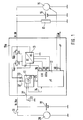
- FIG. 1 shows the configuration of an on-board electrical system control device shown for a two-battery electrical system that the On-board electrical system power supply even when the on-board electrical system battery is empty ensures optimal and gentle loading of both Batteries guaranteed.
- the on-board electrical system control unit 10a consists of a Supply power supply 11, a control and regulating unit 12, e.g. is designed as a bus-compatible microcomputer, a DC converter 13 and a short-circuit proof Power stage 14a, 14b.
- the vehicle electrical system control unit 10a is included its power-side inputs to terminals terminals 30 and Terminal 30a connected.
- terminal 30 is common Way the generator 15, the battery 16, the Supply battery for the vehicle electrical system (vehicle electrical system battery) represents and the load 17 connected.
- the load is 17 representative of the multitude of On-board electrical system consumers specified, the consumers in each case can be switched on via switches, not shown.
- the battery 18 is connected to the terminal 30a is designed as a starter battery and when closed Switch 19 is used to supply starter 20.
- the control unit 10a and the control and regulating unit 12 have a number of inputs and outputs that the Connection to the individual components of the Establish the onboard power supply control unit or the other onboard power supply.
- One of these inputs is designated 21, it serves the Initialization and leads from the power supply 11 to the Switch 22. If this switch 22 is closed, the Field effect transistor 23 of supply power supply 11 connected through. Via a connection 24 between the Power supply unit 11 and the control and regulating unit 12 can the field effect transistor 23 also from the control and Control unit 12 are initialized.
- the Power supply to the control unit 12 from the Supply power supply 11 takes place via connection 25.
- the control and regulating unit 12, or the associated one Microcomputer has further connections 26, 27, 28, 29, 30 and 31, about the information regarding the Switching state of the output stages 14, with respect to the Terminals Cl. 30 and Cl. 30a prevailing voltages U30 and U30a can be fed. Via the port 29 can Control signals are sent to the DC / DC converter 13 become.
- An influence on the Generator 50 possible and connection 31 provides one bidirectional connection for a bus, for example one CAN bus or a body bus. About these connections data or control signals can be exchanged a generator regulation taking into account Operating conditions of the internal combustion engine and one Internal combustion engine regulation taking into account Enable wiring system conditions.
- the power supply 11 of the control device 10 is connected to the two diodes 32, 33, the anode of which is connected to the terminal 30 or terminal 30a, without any further intermediate switch via the field-effect transistor 23 on both batteries.
- the vehicle electrical system control unit 10 is in a “sleep mode” in this state. In this operating state, the current consumption is only a few ⁇ amperes and is therefore below the range of battery self-discharge. The continuous current consumption is therefore negligible.
- the field effect transistor 23 of the Supply power supply 11 switched through and Total supply of the vehicle electrical system control unit 10a activated.
- the control and Control device 12 is the microcomputer first Voltage level on the vehicle electrical system side, i.e. at terminal 30 checked.
- the control and regulating device voltage U30 is fed to the input.
- the vehicle electrical system control unit 10a then waits for the Information that the start has been made. Come this Information not within a given time of for example 30 sec, the total power supply disabled.
- the field effect transistor 23 in Supply power supply 11 is controlled by the Microcomputer switched in a locked state and that Onboard power supply control unit 10a returns to "sleep mode".
- this body bus is also to the microcomputer of the vehicle electrical system control unit connected. From those that can be fed via the body bus Information regarding the outside temperature, the Cooling water temperature or the engine temperature and the Indoor temperature can be controlled by skillful Links the temperatures of the two batteries determine without these temperatures measured yourself should be. Because the battery temperature for the Voltage regulation is an essential quantity, it should be the setting of the target voltage must be taken into account. The Specification of the temperature-dependent charging voltage for the On-board electrical system battery 16 then takes place via a setpoint specification, which is fed to the generator controller.
- the battery 18 provided for the starter supply can as required via a DC / DC converter from the Vehicle electrical system side are supplied so that the temperature is adjusted both a higher and a lower or the same Charging voltage level compared to the vehicle electrical system voltage can be realized.
- the use of a suitable Voltage converter also allows one Charge the starter battery when the on-board electrical system battery is relatively heavily discharged.
- a starter battery Battery used the characteristics of which are specific to the Requirements, such as providing a short-term high current is adjusted.
- Figure 1 can be in the Case in which the vehicle electrical system voltage has dropped too far, accomplish another emergency operation. Will after the Initialization phase and query of the vehicle electrical system voltage recognized that this is a minimum predetermined Falls below the voltage level, the emergency operation triggered. To do this, when falling below the specified Voltage levels of both batteries 16 and 18 from Onboard power supply control unit connected in parallel and so that is On-board electrical system also supplied from the starter battery 16. At the same time, a message is sent Emergency operation information so that consumers are aware of their upstream electronic switches if necessary can be switched off, taking into account that only consumers that are not switched off are function or safety relevant. In addition can an error memory located on the on-board electrical system side can be set or an ad can be triggered.
- the power supply for the Vehicle electrical system control unit 10a interrupted if within the predeterminable time no start has taken place. Then it will be the Batteries 16, 18 separated again and the control unit 10 goes over to sleep mode until by closing the mechanical Switch 22 a new switch-on request is triggered.
- the engine takes Generator 15 does its work in the usual way and the Vehicle electrical system voltage increases after a relatively short time based on the current supplied by the generator. Reached the vehicle electrical system voltage is the defined threshold, we the Parallel connection of the two batteries canceled again, the control pulse required for this from the control and control device 12 is triggered. After opening the Connection between the two batteries 16 and 18 will be this according to the procedure described under point 1 charged, the battery 18 for supplying the starter 20 loading priority, so even after a short time Driving operation sufficient for a subsequent start Energy is available.
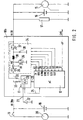
- FIG. 2 is a second embodiment of the invention shown, in which the short-circuit-proof output stage and Voltage converter according to the exemplary embodiment according to FIG. 1 is replaced by a power unit with converter 34.
- This Power section with converter consists of the Field effect transistors 35, 36 and 37, the inductance 38, which acts as a choke, and the freewheeling diode 39. Between the power section with converter 34 and the microcomputer of Control and regulating part 12 are different connections available, some of the connections according to 1 correspond to the exemplary embodiment. Same Components have the designations known from FIG. 1. Additional connections or connections 41, 42, 43, 44, 45 are available via which the control and regulating device 12 Information regarding the supply current IV and the Voltage UME can be supplied. The supply current IV is measured between transistor 35 and inductance 38, the voltage UME at the point ME. Control signals S35, S36, S37 to the transistors 35, 36 and 37 are connected to the Connections or connections 43, 44 and 45 issued.
- the electrical system control unit 10b shown in FIG. 2 basically works in normal operation according to the same principle as the electrical system control unit 10a according to FIG. 1.
- the operation of the electrical system control unit according to FIG. 2 in emergency operation can be described as follows: If the evaluation of the vehicle electrical system voltage after the initialization phase leads to the result that it is smaller than a predeterminable minimum value, the vehicle electrical system control unit 10a switches the two batteries 16 and 18 in parallel and the vehicle electrical system is also supplied via the starter battery 18. In this case, transistor 35 and transistor 37 are conductive, while transistor 36 is blocked.
- the system is switched to normal operation with a voltage increase, which causes the voltage U30a to be greater than U30.
- the transistor 37 is then turned on, the transistors 35 and 36 then clock in push-pull operation.
- the transistor 37 is operated in a clocked manner.
- Transistor 36 turns off and transistor 35 turns on.
- the two embodiments of the invention were for a Vehicle electrical system selected. Basically, one can Vehicle electrical system control device according to the invention also in others Use two-battery supply systems. Also one Expansion to more than two batteries is essential possible.
Landscapes
- Engineering & Computer Science (AREA)
- Power Engineering (AREA)
- Control Of Charge By Means Of Generators (AREA)
- Charge And Discharge Circuits For Batteries Or The Like (AREA)
- Direct Current Feeding And Distribution (AREA)
Description
Führt die Auswertung der Bordnetzspannung nach der Initialisierungsphase zu dem Ergebnis, daß sie kleiner ist als ein vorgebbarer Minimalwert, schaltet das Bordnetzsteuergerät 10a die beiden Batterien 16 und 18 parallel und das Bordnetz wird über die Starterbatterie 18 mitversorgt. In diesem Fall ist der Transistor 35 und der Transistor 37 leitend, während der Transistor 36 gesperrt ist. Übersteigt die Bordnetzspannung nach Anlaufen des Motors und damit nach Stromabgabe durch den Generator 15 das vorgegebene Spannungsniveau, wird auf Normalbetrieb umgeschaltet mit einer Spannungserhöhung, die bewirkt, daß die Spannung U30a größer ist als U30. Es wird dann der Transistor 37 leitend geschaltet, die Transistoren 35 und 36 takten dann im Gegentaktbetrieb. Bei einer Spannungserniedrigung, bei der die Spannung U30a kleiner ist als die Spannung U30 wird der Transistor 37 getaktet betrieben. Der Transistor 36 sperrt und der Transistor 35 wird eingeschaltet.
Claims (6)
- Steuergerät (10a, 10b) für ein Bordnetz mit wenigstens zwei von einem Generator (50) aufladbaren Batterien, (16, 18) die zur Versorgung erster und zweiter Verbraucher (17) dienen und über das Steuergerät (10a, 10b) miteinander in Verbindung stehen, wobei die Verbindung der beiden Batterien (16, 18) nur bei vorgebbaren Bedingungen erfolgt, dadurch gekennzeichnet, daß das Steuergerät (10a, 10b) ein Versorgungsnetzteil (11) mit wenigstens einem Feldeffekttransistor (23) umfaßt und über Mittel zur Spannungsbegrenzung (32, 33) mit den Batterien (16, 18) in Verbindung steht und der Feldeffekttransistor (23) zur Inbetriebnahme des Steuergerätes (10a, 10b) durch Zuführung eines Signales durchgeschaltet wird.
- Steuergerät für ein Bordnetz nach Anspruch 1, dadurch gekennzeichnet, daß eine Steuer- und Regeleinheit (12), die einen Mikrocomputer umfaßt, als Bestandteil des Steuergerätes (10a, 10b) vorhanden ist und die Steuer- und Regelvorgänge auslöst.
- Steuergerät für ein Bordnetz nach Anspruch 2, dadurch gekennzeichnet, daß der Steuer- und Regeleinheit (12) über Eingänge Informationen zugeführt werden und die Steuer- und Regeleinheit (12) in Abhängigkeit von diesen Informationen Ansteuersignale ermittelt, die über Verbindungen an einzelne Komponenten des Steuergerätes und/oder des Bordnetzes abgegeben werden.
- Steuergerät für ein Bordnetz nach einem der vorhergehenen Ansprüche, dadurch gekennzeichnet, daß ein von der Steuer- und Regeleinheit ansteuerbarer Gleichspannungswandler in Serie zwischen die beiden Batterien (16) und (18) schaltbar ist.
- Steuergerät für ein Bordnetz nach einem der vorhergehenden Ansprüche, dadurch gekennzeichnet, daß ein Leistungsteil mit Wandler vorhanden ist, das in der Verbindung zwischen den beiden Batterien (16) und (18) liegt, das Daten an die Steuereinheit (12) abgibt und von dieser Ansteuersignale empfängt.
- Steuergerät nach Anspruch 5, dadurch gekennzeichnet, daß das Leistungsteil mit Wandler eine Serienschaltung aus erstern Transistor (35), Drossel (38) und zweitern Transistor (37) umfaßt, wobei zwischen je einem Anschluß der Drossel (38) und Masse ein weiterer Transistor (36) bzw. eine Diode (39) liegt.
Applications Claiming Priority (3)
| Application Number | Priority Date | Filing Date | Title |
|---|---|---|---|
| DE19645944A DE19645944A1 (de) | 1996-11-07 | 1996-11-07 | Steuergerät für ein Bordnetz |
| DE19645944 | 1996-11-07 | ||
| PCT/DE1997/002332 WO1998019890A1 (de) | 1996-11-07 | 1997-10-11 | Steuergerät für ein bordnetz |
Publications (2)
| Publication Number | Publication Date |
|---|---|
| EP0935540A1 EP0935540A1 (de) | 1999-08-18 |
| EP0935540B1 true EP0935540B1 (de) | 2001-09-26 |
Family
ID=7810943
Family Applications (1)
| Application Number | Title | Priority Date | Filing Date |
|---|---|---|---|
| EP97945739A Expired - Lifetime EP0935540B1 (de) | 1996-11-07 | 1997-10-11 | Steuergerät für ein bordnetz |
Country Status (6)
| Country | Link |
|---|---|
| US (1) | US6232674B1 (de) |
| EP (1) | EP0935540B1 (de) |
| JP (1) | JP4036901B2 (de) |
| DE (2) | DE19645944A1 (de) |
| ES (1) | ES2165094T3 (de) |
| WO (1) | WO1998019890A1 (de) |
Families Citing this family (101)
| Publication number | Priority date | Publication date | Assignee | Title |
|---|---|---|---|---|
| DE19839997C1 (de) * | 1998-09-02 | 2000-06-21 | Siemens Ag | Elektronische Schaltungsanordnung |
| SE514786C2 (sv) * | 1998-09-02 | 2001-04-23 | Scania Cv Ab | Elsystem för motorfordon med dubbla batterier |
| DE19931144B9 (de) * | 1998-09-08 | 2013-02-07 | Volkswagen Ag | Verfahren zum Betreiben eines elektrischen Fahrzeug-Bordnetzes |
| DE19903426A1 (de) | 1999-01-29 | 2000-08-03 | Bosch Gmbh Robert | Vorrichung und Verfahren zur Regelung eines Generators mit zugeordnetem Spannungswandler |
| FR2790147B1 (fr) * | 1999-02-19 | 2003-09-26 | Sagem | Dispositif de transfert de courant de charge entre deux batteries |
| DE19913131B4 (de) * | 1999-03-23 | 2004-07-22 | Siemens Ag | Stromversorgungssystem mit zwei Batterien unterschiedlicher Spannung |
| WO2000076812A1 (es) * | 1999-06-09 | 2000-12-21 | Lear Automotive (Eeds) Spain, S.L. | Caja de distrubucion electrica para vehiculos con dos redes a niveles de tensión distintos |
| DE19941481B4 (de) * | 1999-09-01 | 2009-07-09 | Robert Bosch Gmbh | Elektrisch gesteuertes, dezentrales Steuersystem in einem Fahrzeug |
| DE19941699A1 (de) | 1999-09-02 | 2001-03-08 | Bosch Gmbh Robert | Halbleitersicherung für elektrische Verbraucher |
| DE19951128A1 (de) * | 1999-10-23 | 2001-04-26 | Bosch Gmbh Robert | Verfahren und Vorrichtung zur Spannungsregelung |
| DE19955721A1 (de) * | 1999-11-15 | 2001-05-17 | Volkswagen Ag | Zwei-Batteriensystem |
| DE19957477A1 (de) * | 1999-11-23 | 2001-05-31 | Volkswagen Ag | Kraftfahrzeug-Bordnetz |
| ES2164578B1 (es) * | 1999-12-24 | 2003-05-16 | Lear Automotive Eeds Spain | Convertidor en "interleaving" de energia electrica continua-continua. |
| DE10008266A1 (de) | 2000-02-23 | 2001-08-30 | Bosch Gmbh Robert | Vorrichtung zur Ein- und Ausschaltung eines Steuergerätes |
| JP2001327158A (ja) * | 2000-05-12 | 2001-11-22 | Toyota Motor Corp | 電圧変換器の電源回路 |
| DE10028748B4 (de) * | 2000-06-10 | 2009-06-04 | Bayerische Motoren Werke Aktiengesellschaft | Energieversorgungssystem für ein Kraftfahrzeug mit einem Niedrigspannungsbordnetz und mit einem Höherspannungsbordnetz |
| FR2812474B1 (fr) * | 2000-07-31 | 2004-06-18 | Valeo Climatisation | Dispositif de protection d'une source electrique propre a alimenter un organe electrique |
| US6455951B1 (en) * | 2000-08-16 | 2002-09-24 | Yazaki North America, Inc. | Auto charger for system including a high voltage supply and a low voltage supply |
| DE10100889B4 (de) * | 2001-01-11 | 2013-11-14 | Robert Bosch Gmbh | Verfahren und Vorrichtung zur Realisierung eines Start/Stopp-Betriebes bei Fahrzeugen |
| DE10109796A1 (de) | 2001-03-01 | 2002-09-05 | Bosch Gmbh Robert | Schaltung und Verfahren zur Vorgabe eines Startsignals für einen Controller |
| JP3886741B2 (ja) * | 2001-06-07 | 2007-02-28 | 三菱電機株式会社 | 内燃機関制御装置のための電源システム |
| WO2003004315A2 (de) | 2001-06-29 | 2003-01-16 | Robert Bosch Gmbh | Vorrichtungen und/oder verfahren zur bestimmung der verfügbarkeit von elektrischer energie insbesondere in bordnetzen mit mehreren energiespeichern |
| ES2181606B1 (es) * | 2001-08-08 | 2004-08-16 | Lear Automotive (Eeds) Spain, S.L. | Sistema y metodo de distribucion electrica para un vehiculo con dos redes a diferentes niveles de tension. |
| EP1462315B1 (de) * | 2001-11-27 | 2007-02-21 | Lear Automotive (EEDS) Spain, S.L. | System und verfahren zum schutz gegen kurzschlüsse in elektrischen leistungsverteilungsarchitekturen mit zwei spannungspegeln |
| FR2833113B1 (fr) * | 2001-11-30 | 2004-07-09 | Valeo Equip Electr Moteur | Convertisseur de courant electrique continu en courant continu reversible pour reseau bitension et reseau bitension equipe d'un tel convertisseur |
| US6437462B1 (en) * | 2001-12-10 | 2002-08-20 | Delphi Technologies, Inc. | Bi-directional DC/DC converter and control method therefor |
| ES2189696B1 (es) * | 2001-12-27 | 2004-11-16 | Lear Automotive (Eeds) Spain, S.L | Sistema de gestion de un vehiculo con doble bateria y metodo. |
| US6924621B2 (en) | 2002-05-07 | 2005-08-02 | C.E. Niehoff & Co. | System and method for controlling electric load and battery charge in a vehicle |
| WO2003105330A2 (de) | 2002-06-11 | 2003-12-18 | Daimlerchrysler Ag | Anordnung zur spannungsversorgung mehrerer verbraucher und steuergerät fur ein mindestens zwei energiespeicher umfassendes bordnetz |
| FR2848033B1 (fr) * | 2002-12-03 | 2008-08-29 | Renault Sas | Systeme et procede d'alimentation electrique a deux tensions pour vehicule. |
| DE10304764B3 (de) | 2003-02-05 | 2004-02-26 | Daimlerchrysler Ag | Zwei-Spannungs-Bordnetz |
| US20070183109A1 (en) * | 2003-02-13 | 2007-08-09 | Poweready, Inc. | Safety circuit technique for high current shut-down |
| JP4120418B2 (ja) * | 2003-02-17 | 2008-07-16 | 株式会社デンソー | 自動車用電源装置 |
| EP2154028B8 (de) * | 2003-02-17 | 2015-12-09 | Denso Corporation | Fahrzeugstromversorgungssystem |
| US7614381B2 (en) * | 2003-03-28 | 2009-11-10 | Caterpillar Inc. | Power system with an integrated lubrication circuit |
| JP2004338577A (ja) * | 2003-05-16 | 2004-12-02 | Hitachi Ltd | 車両用電力供給装置及び電力供給方法 |
| DE10346325A1 (de) | 2003-10-06 | 2005-05-04 | Siemens Ag | Schaltvorrichtung zum bidirektionalen Ladungsausgleich zwischen Energiespeichern |
| US7176585B2 (en) * | 2003-12-29 | 2007-02-13 | Temic Automotive Of North America, Inc. | Power distribution web node and power management process |
| US7157806B2 (en) * | 2004-03-12 | 2007-01-02 | C. E. Niehoff & Co. | System and method for controlling and distributing electrical energy in a vehicle |
| JP4211715B2 (ja) | 2004-08-23 | 2009-01-21 | 株式会社デンソー | 車載電源システム |
| FR2879040B1 (fr) * | 2004-12-03 | 2007-11-30 | Jean Paul Siaudeau | Coupleur de batteries |
| US7362005B2 (en) * | 2005-03-10 | 2008-04-22 | Red Tech Inc. | Isolated dual battery system |
| SE528232C2 (sv) * | 2005-04-08 | 2006-09-26 | Creator Teknisk Utveckling Ab | Batteriladdningsanordning |
| IL169549A0 (en) * | 2005-07-06 | 2007-07-04 | Yeshua Rahamim Levi | A self report over a traffic felony |
| ATE405021T1 (de) * | 2005-10-10 | 2008-08-15 | Fiat Ricerche | Elektrisches versorgungssystem eines kraftfahrzeugs |
| JP4449940B2 (ja) * | 2006-05-16 | 2010-04-14 | トヨタ自動車株式会社 | 車両用二電源システム |
| DE102006037125A1 (de) | 2006-08-09 | 2008-02-14 | Daimler Ag | Ansteuersystem für eine Antriebseinheit eines Kraftfahrzeuges |
| US20090033155A1 (en) * | 2007-06-08 | 2009-02-05 | Renesas Technology Corp. | Semiconductor integrated circuits |
| US9579961B2 (en) * | 2007-09-24 | 2017-02-28 | Scott C Harris | Hybrid vehicle with modular battery system |
| DE102007062955B4 (de) * | 2007-12-21 | 2011-06-01 | Catem Develec Gmbh & Co. Kg | Schaltung zur Spannungsstabilisierung eines Bordnetzes |
| SE532001C2 (sv) * | 2008-02-04 | 2009-09-22 | Scania Cv Abp | Elsystem för ett motorfordon och förfarande för styrning av en startmotor och en batterifrånskiljare i ett sådant elsystem |
| MX2010011150A (es) * | 2008-04-21 | 2010-11-05 | Int Truck Intellectual Prop Co | Sistema de baterias multiples para un vehiculo de motor. |
| US8076797B2 (en) * | 2008-05-15 | 2011-12-13 | Indy Power Systems Llc | Energy transfer circuit and method |
| US8295950B1 (en) | 2008-07-02 | 2012-10-23 | Jerry Lee Wordsworth | Intelligent power management system |
| WO2010044037A2 (en) * | 2008-10-17 | 2010-04-22 | Koninklijke Philips Electronics, N.V. | Power control in a medical ventilator |
| DE102008054885B4 (de) * | 2008-12-18 | 2014-09-18 | Lisa Dräxlmaier GmbH | Vorrichtung und Verfahren zum Steuern einer Energieversorgung eines Bordnetzes eines Fahrzeugs |
| JP2011004556A (ja) * | 2009-06-22 | 2011-01-06 | Mitsubishi Electric Corp | 車両用電源装置 |
| DE102009041872B4 (de) * | 2009-09-16 | 2014-10-30 | Hella Kgaa Hueck & Co. | Schaltungsanordnung zur Bordnetzstabilisierung mit einem Gleichstromsteller |
| US20110084665A1 (en) * | 2009-10-09 | 2011-04-14 | Christopher White | Method and apparatus of stored energy management in battery powered vehicles |
| US8314587B2 (en) * | 2009-10-09 | 2012-11-20 | Alcatel Lucent | Method and apparatus of stored energy management in battery powered vehicles |
| US20130037531A1 (en) | 2009-11-06 | 2013-02-14 | Rick Gray | Electrically heated garment |
| US20110108538A1 (en) | 2009-11-06 | 2011-05-12 | Rick Gray | Electrically heated garment |
| JP5234052B2 (ja) * | 2010-04-27 | 2013-07-10 | 株式会社デンソー | 電源装置 |
| DE102010030160B4 (de) * | 2010-06-16 | 2023-10-12 | Bayerische Motoren Werke Aktiengesellschaft | Verfahren und Steuergerät zur Verarbeitung von Daten in einem Netzwerk eines Fahrzeugs |
| US8981710B2 (en) | 2010-09-20 | 2015-03-17 | Indy Power Systems Llc | Energy management system |
| DE102011101531B4 (de) * | 2011-05-14 | 2015-09-24 | Volkswagen Aktiengesellschaft | Kraftfahrzeugbordnetz und Verfahren zum Betreiben eines Kraftfahrzeugbordnetzes |
| JP5488529B2 (ja) * | 2011-05-17 | 2014-05-14 | マツダ株式会社 | 車両の電源制御装置 |
| FR2975839B1 (fr) * | 2011-05-23 | 2013-05-17 | Renault Sa | Procede de rechargement d'un couple de batteries de vehicule de tensions nominales differentes, et systeme associe |
| JP5847506B2 (ja) * | 2011-09-14 | 2016-01-20 | 株式会社ケーヒン | 電子制御装置及び車両制御システム |
| DE102011086829A1 (de) | 2011-11-22 | 2013-05-23 | Continental Automotive Gmbh | Bordnetz und Verfahren zum Betreiben eines Bordnetzes |
| JP5477409B2 (ja) | 2012-03-12 | 2014-04-23 | 株式会社デンソー | 電源システム |
| DE102012215374A1 (de) * | 2012-08-30 | 2014-05-28 | Bayerische Motoren Werke Aktiengesellschaft | Umladefunktion bei Nichtstart |
| WO2014055530A1 (en) * | 2012-10-01 | 2014-04-10 | Thermo King Corporation | Methods and systems for starting an electrically controlled engine of a transport refrigeration system |
| DE102012024652B4 (de) | 2012-12-17 | 2025-07-17 | Volkswagen Aktiengesellschaft | Kraftfahrzeug mit einem Starter-Generator |
| FR3001931A1 (fr) * | 2013-02-14 | 2014-08-15 | Peugeot Citroen Automobiles Sa | Dispositif de gestion de transfert d'energie depuis et vers un stockeur d'energie electrique d'un vehicule |
| DE102013206298A1 (de) * | 2013-04-10 | 2014-10-16 | Robert Bosch Gmbh | Verfahren zum Betreiben eines Mehrspannungsbordnetzes eines Kraftfahrzeugs, Mehrspannungsbordnetz und Mittel zur Implementierung des Verfahrens |
| JP5907118B2 (ja) | 2013-05-22 | 2016-04-20 | 株式会社デンソー | 電源システム異常検出装置 |
| US9682672B2 (en) * | 2013-09-18 | 2017-06-20 | Flextronics Ap, Llc | Device and method for current flow control for dual battery vehicle architecture |
| DE102013219751A1 (de) * | 2013-09-30 | 2015-04-02 | Siemens Aktiengesellschaft | Verfahren zum Betreiben eines Schienenfahrzeugs |
| US9812949B2 (en) | 2013-10-10 | 2017-11-07 | Indy Power Systems Llc | Poly-phase inverter with independent phase control |
| DE102013221043B4 (de) * | 2013-10-17 | 2026-03-26 | Bayerische Motoren Werke Aktiengesellschaft | Notstartvorrichtung |
| CN103707772B (zh) * | 2014-01-08 | 2016-04-06 | 上汽通用五菱汽车股份有限公司 | 一种电动汽车的上下电控制电路及方法 |
| JP6221796B2 (ja) * | 2014-02-07 | 2017-11-01 | 株式会社デンソー | 電池ユニット及び電源システム |
| JP6090195B2 (ja) * | 2014-02-10 | 2017-03-08 | 株式会社デンソー | 電池ユニット |
| DE102014203030B4 (de) * | 2014-02-19 | 2021-06-02 | Vitesco Technologies GmbH | Verfahren zum gesteuerten Verbinden mehrerer Bordnetzzweige eines Fahrzeugs, Steuereinheit zur Ausführung des Verfahrens sowie Fahrzeugbordnetz |
| USD808616S1 (en) | 2014-02-28 | 2018-01-30 | Milwaukee Electric Tool Corporation | Single control button for an article of clothing |
| US11033059B2 (en) | 2014-11-06 | 2021-06-15 | Milwaukee Electric Tool Corporation | Article of clothing with control button |
| JP6079760B2 (ja) * | 2014-12-04 | 2017-02-15 | マツダ株式会社 | 車両用電源制御装置 |
| JP6380171B2 (ja) | 2015-03-06 | 2018-08-29 | 株式会社デンソー | 電源システム |
| DE102015214415A1 (de) | 2015-07-29 | 2017-02-02 | Robert Bosch Gmbh | Verfahren und Vorrichtung zum energiesparenden Betreiben eines Steuergerätes |
| FR3043281B1 (fr) * | 2015-10-30 | 2017-12-08 | Peugeot Citroen Automobiles Sa | Dispositif de controle actif pour un circuit electrique a convertisseur dc/dc et stockeur d’energie electrique montes en serie |
| DE102016101081A1 (de) * | 2016-01-22 | 2017-07-27 | Eberspächer Controls Landau Gmbh & Co. Kg | Bordnetz für ein Fahrzeug |
| JP6748906B2 (ja) * | 2016-04-15 | 2020-09-02 | 株式会社オートネットワーク技術研究所 | リレー装置 |
| JP6750288B2 (ja) * | 2016-04-15 | 2020-09-02 | 株式会社オートネットワーク技術研究所 | リレー装置 |
| GB2574196B (en) | 2018-05-21 | 2022-08-24 | Bae Systems Plc | Supercapacitor arrangement for enhancing electronic power performance of waterborne vehicles |
| US11421641B2 (en) * | 2019-02-15 | 2022-08-23 | Kold-Ban International Ltd. | Supplemental starting system |
| DE102020122508B4 (de) * | 2020-08-28 | 2025-10-02 | Knorr-Bremse Systeme für Nutzfahrzeuge GmbH | Energieversorgungsvorrichtung, verfahren zum versorgen zumindest eines elektrischen verbrauchers und fahrzeug |
| JP7349069B2 (ja) * | 2020-09-16 | 2023-09-22 | 株式会社オートネットワーク技術研究所 | 駆動装置 |
| US11744298B2 (en) | 2020-12-04 | 2023-09-05 | Milwaukee Electric Tool Corporation | Electrically heated garment with pass-through battery pocket |
| USD1020226S1 (en) | 2021-10-21 | 2024-04-02 | Milwaukee Electric Tool Corporation | Control button for heated garment |
| JP7632380B2 (ja) * | 2022-04-22 | 2025-02-19 | トヨタ自動車株式会社 | 電源制御装置、制御方法、及び制御プログラム |
Family Cites Families (18)
| Publication number | Priority date | Publication date | Assignee | Title |
|---|---|---|---|---|
| GB2036468B (en) * | 1978-02-13 | 1982-08-25 | Pettersson D | Battery separator |
| JPS5930643U (ja) * | 1982-08-23 | 1984-02-25 | パイオニア株式会社 | 充放電回路 |
| GB2136224A (en) * | 1983-03-02 | 1984-09-12 | Ford Motor Co | Vehicle electrical system |
| JP2516327Y2 (ja) * | 1989-07-20 | 1996-11-06 | 本田技研工業株式会社 | 直流電源装置 |
| JPH0748934B2 (ja) * | 1990-04-16 | 1995-05-24 | 日本電装株式会社 | 乗員保護装置の故障検出装置 |
| JP3189311B2 (ja) * | 1990-09-05 | 2001-07-16 | 株式会社デンソー | 自動車搭載電子機器の電源装置 |
| DE4028242C2 (de) * | 1990-09-06 | 1997-08-07 | Bayerische Motoren Werke Ag | Bordnetz für Kraftfahrzeuge |
| DE4138943C1 (de) | 1991-11-27 | 1993-05-27 | Robert Bosch Gmbh, 7000 Stuttgart, De | |
| JP3039119B2 (ja) * | 1992-03-31 | 2000-05-08 | 日産自動車株式会社 | 車両用電源装置 |
| US5316868A (en) * | 1992-07-21 | 1994-05-31 | Globe-Union, Inc. | Dual battery switch circuit |
| JP2941145B2 (ja) * | 1993-06-01 | 1999-08-25 | 株式会社ピーエフユー | 電源装置 |
| US5488283A (en) * | 1993-09-28 | 1996-01-30 | Globe-Union, Inc. | Vehicle battery system providing battery back-up and opportunity charging |
| US5569997A (en) * | 1993-10-04 | 1996-10-29 | Ford Motor Company | Power supply for volatile memory devices and portable electrical appliance in vehicles |
| JP3014573B2 (ja) * | 1993-11-04 | 2000-02-28 | 三菱電機株式会社 | 車両用電源電圧切換装置 |
| US5481175A (en) * | 1993-12-20 | 1996-01-02 | Motorola, Inc. | System and method for charging auxiliary batteries |
| JPH07309210A (ja) * | 1994-05-19 | 1995-11-28 | Nippondenso Co Ltd | 電気自動車用ウインドシールド加熱装置 |
| JPH08132992A (ja) * | 1994-11-10 | 1996-05-28 | Mitsubishi Electric Corp | 車載用制御装置 |
| DE19530721A1 (de) * | 1995-08-18 | 1997-02-20 | Kiekert Ag | Steuerungsanlage für ein Kraftfahrzeug mit einer Notstrombatterie sowie einer Notbetriebsschaltung |
-
1996
- 1996-11-07 DE DE19645944A patent/DE19645944A1/de not_active Withdrawn
-
1997
- 1997-10-11 ES ES97945739T patent/ES2165094T3/es not_active Expired - Lifetime
- 1997-10-11 JP JP52093298A patent/JP4036901B2/ja not_active Expired - Fee Related
- 1997-10-11 EP EP97945739A patent/EP0935540B1/de not_active Expired - Lifetime
- 1997-10-11 DE DE59704732T patent/DE59704732D1/de not_active Expired - Lifetime
- 1997-10-11 US US09/284,306 patent/US6232674B1/en not_active Expired - Lifetime
- 1997-10-11 WO PCT/DE1997/002332 patent/WO1998019890A1/de not_active Ceased
Also Published As
| Publication number | Publication date |
|---|---|
| JP4036901B2 (ja) | 2008-01-23 |
| JP2001503703A (ja) | 2001-03-21 |
| WO1998019890A1 (de) | 1998-05-14 |
| DE59704732D1 (de) | 2001-10-31 |
| DE19645944A1 (de) | 1998-05-14 |
| EP0935540A1 (de) | 1999-08-18 |
| ES2165094T3 (es) | 2002-03-01 |
| US6232674B1 (en) | 2001-05-15 |
Similar Documents
| Publication | Publication Date | Title |
|---|---|---|
| EP0935540B1 (de) | Steuergerät für ein bordnetz | |
| EP0568655B1 (de) | Vorrichtung zur spannungsversorgung in einem kraftfahrzeug | |
| DE102012222208B4 (de) | Verfahren zum gesteuerten Verbinden mehrerer Bordnetzzweige eines Fahrzeugs, Steuereinheit zur Ausführung des Verfahrens sowie Bordnetz | |
| DE102014203030B4 (de) | Verfahren zum gesteuerten Verbinden mehrerer Bordnetzzweige eines Fahrzeugs, Steuereinheit zur Ausführung des Verfahrens sowie Fahrzeugbordnetz | |
| EP2160813B1 (de) | Kraftfahrzeugbordnetz | |
| EP0850506B1 (de) | Vorrichtung zur spannungsversorgung in einem kraftfahrzeug | |
| EP1232073B1 (de) | Zwei-batteriensystem | |
| EP2805396B1 (de) | Bordnetz | |
| DE102008054885B4 (de) | Vorrichtung und Verfahren zum Steuern einer Energieversorgung eines Bordnetzes eines Fahrzeugs | |
| EP3022432B1 (de) | Elektronische sicherheitsabschaltung für kraftfahrzeuge | |
| EP3022433B1 (de) | Schalteranordnung in kraftfahrzeugbordnetz | |
| DE112017006219B4 (de) | Fahrzeugmontierte Energieversorgungsvorrichtung | |
| EP2822808B1 (de) | Bordnetz für ein fahrzeug | |
| DE69813862T2 (de) | Verfahren und einrichtung zur ladesteuerung in einem elektrischen system mit zwei batterien | |
| DE102010029788B4 (de) | Bordnetz und Verfahren und Vorrichtung zum Betreiben des Bordnetzes | |
| WO2013160031A1 (de) | Kraftfahrzeugbordnetz mit wenigstens zwei teilnetzen | |
| EP1104719B1 (de) | Stromversorgung für Fahrzeuge | |
| DE102018006582B4 (de) | Batterie für ein Kraftfahrzeug und Kraftfahrzeugbordnetz | |
| WO2017202537A1 (de) | Kraftfahrzeugbordnetz mit wenigstens zwei energiespeichern, verfahren zum betreiben eines kraftfahrzeugbordnetzes und mittel zu dessen implementierung | |
| DE10228350A1 (de) | Energiebordnetz zur Versorgung eines Hochleistungsverbrauchers | |
| EP1318590B1 (de) | Stromversorgungseinrichtung mit zwei Akkumulatoren und zwei Generatoren in einem Nutzfahrzeug | |
| DE102008012640A1 (de) | Vorrichtung zur Kopplung mehrerer Teilnetze | |
| EP1044852A2 (de) | Bordnetz für Kraftfahrzeuge | |
| DE102013009991A1 (de) | Fremdstartfähige Integration einer Batterie in ein Kraftfahrzeug-Bordnetz | |
| DE102012218591A1 (de) | Bordnetz und Verfahren zum Betreiben eines Bordnetzes |
Legal Events
| Date | Code | Title | Description |
|---|---|---|---|
| PUAI | Public reference made under article 153(3) epc to a published international application that has entered the european phase |
Free format text: ORIGINAL CODE: 0009012 |
|
| 17P | Request for examination filed |
Effective date: 19990607 |
|
| AK | Designated contracting states |
Kind code of ref document: A1 Designated state(s): DE ES FR GB IT SE |
|
| GRAG | Despatch of communication of intention to grant |
Free format text: ORIGINAL CODE: EPIDOS AGRA |
|
| 17Q | First examination report despatched |
Effective date: 20001128 |
|
| GRAG | Despatch of communication of intention to grant |
Free format text: ORIGINAL CODE: EPIDOS AGRA |
|
| GRAH | Despatch of communication of intention to grant a patent |
Free format text: ORIGINAL CODE: EPIDOS IGRA |
|
| GRAH | Despatch of communication of intention to grant a patent |
Free format text: ORIGINAL CODE: EPIDOS IGRA |
|
| GRAA | (expected) grant |
Free format text: ORIGINAL CODE: 0009210 |
|
| AK | Designated contracting states |
Kind code of ref document: B1 Designated state(s): DE ES FR GB IT SE |
|
| REF | Corresponds to: |
Ref document number: 59704732 Country of ref document: DE Date of ref document: 20011031 |
|
| ET | Fr: translation filed | ||
| REG | Reference to a national code |
Ref country code: GB Ref legal event code: IF02 |
|
| GBT | Gb: translation of ep patent filed (gb section 77(6)(a)/1977) |
Effective date: 20011201 |
|
| REG | Reference to a national code |
Ref country code: ES Ref legal event code: FG2A Ref document number: 2165094 Country of ref document: ES Kind code of ref document: T3 |
|
| PLBE | No opposition filed within time limit |
Free format text: ORIGINAL CODE: 0009261 |
|
| STAA | Information on the status of an ep patent application or granted ep patent |
Free format text: STATUS: NO OPPOSITION FILED WITHIN TIME LIMIT |
|
| 26N | No opposition filed | ||
| PGFP | Annual fee paid to national office [announced via postgrant information from national office to epo] |
Ref country code: SE Payment date: 20131022 Year of fee payment: 17 Ref country code: FR Payment date: 20131018 Year of fee payment: 17 Ref country code: GB Payment date: 20131022 Year of fee payment: 17 |
|
| PGFP | Annual fee paid to national office [announced via postgrant information from national office to epo] |
Ref country code: ES Payment date: 20131022 Year of fee payment: 17 Ref country code: IT Payment date: 20131030 Year of fee payment: 17 |
|
| PGFP | Annual fee paid to national office [announced via postgrant information from national office to epo] |
Ref country code: DE Payment date: 20131217 Year of fee payment: 17 |
|
| REG | Reference to a national code |
Ref country code: DE Ref legal event code: R119 Ref document number: 59704732 Country of ref document: DE |
|
| REG | Reference to a national code |
Ref country code: SE Ref legal event code: EUG |
|
| GBPC | Gb: european patent ceased through non-payment of renewal fee |
Effective date: 20141011 |
|
| PG25 | Lapsed in a contracting state [announced via postgrant information from national office to epo] |
Ref country code: DE Free format text: LAPSE BECAUSE OF NON-PAYMENT OF DUE FEES Effective date: 20150501 Ref country code: GB Free format text: LAPSE BECAUSE OF NON-PAYMENT OF DUE FEES Effective date: 20141011 Ref country code: SE Free format text: LAPSE BECAUSE OF NON-PAYMENT OF DUE FEES Effective date: 20141012 |
|
| REG | Reference to a national code |
Ref country code: FR Ref legal event code: ST Effective date: 20150630 |
|
| PG25 | Lapsed in a contracting state [announced via postgrant information from national office to epo] |
Ref country code: FR Free format text: LAPSE BECAUSE OF NON-PAYMENT OF DUE FEES Effective date: 20141031 Ref country code: IT Free format text: LAPSE BECAUSE OF NON-PAYMENT OF DUE FEES Effective date: 20141011 |
|
| REG | Reference to a national code |
Ref country code: ES Ref legal event code: FD2A Effective date: 20151127 |
|
| PG25 | Lapsed in a contracting state [announced via postgrant information from national office to epo] |
Ref country code: ES Free format text: LAPSE BECAUSE OF NON-PAYMENT OF DUE FEES Effective date: 20141012 |