EP0935540B1 - Control unit for the power supply system on-board - Google Patents
Control unit for the power supply system on-board Download PDFInfo
- Publication number
- EP0935540B1 EP0935540B1 EP97945739A EP97945739A EP0935540B1 EP 0935540 B1 EP0935540 B1 EP 0935540B1 EP 97945739 A EP97945739 A EP 97945739A EP 97945739 A EP97945739 A EP 97945739A EP 0935540 B1 EP0935540 B1 EP 0935540B1
- Authority
- EP
- European Patent Office
- Prior art keywords
- electrical system
- control device
- control unit
- loop
- batteries
- Prior art date
- Legal status (The legal status is an assumption and is not a legal conclusion. Google has not performed a legal analysis and makes no representation as to the accuracy of the status listed.)
- Expired - Lifetime
Links
Images
Classifications
-
- H—ELECTRICITY
- H02—GENERATION; CONVERSION OR DISTRIBUTION OF ELECTRIC POWER
- H02J—CIRCUIT ARRANGEMENTS OR SYSTEMS FOR SUPPLYING OR DISTRIBUTING ELECTRIC POWER; SYSTEMS FOR STORING ELECTRIC ENERGY
- H02J7/00—Circuit arrangements for charging or depolarising batteries or for supplying loads from batteries
- H02J7/14—Circuit arrangements for charging or depolarising batteries or for supplying loads from batteries for charging batteries from dynamo-electric generators driven at varying speed, e.g. on vehicle
- H02J7/1423—Circuit arrangements for charging or depolarising batteries or for supplying loads from batteries for charging batteries from dynamo-electric generators driven at varying speed, e.g. on vehicle with multiple batteries
-
- H—ELECTRICITY
- H02—GENERATION; CONVERSION OR DISTRIBUTION OF ELECTRIC POWER
- H02M—APPARATUS FOR CONVERSION BETWEEN AC AND AC, BETWEEN AC AND DC, OR BETWEEN DC AND DC, AND FOR USE WITH MAINS OR SIMILAR POWER SUPPLY SYSTEMS; CONVERSION OF DC OR AC INPUT POWER INTO SURGE OUTPUT POWER; CONTROL OR REGULATION THEREOF
- H02M3/00—Conversion of dc power input into dc power output
- H02M3/02—Conversion of dc power input into dc power output without intermediate conversion into ac
- H02M3/04—Conversion of dc power input into dc power output without intermediate conversion into ac by static converters
- H02M3/10—Conversion of dc power input into dc power output without intermediate conversion into ac by static converters using discharge tubes with control electrode or semiconductor devices with control electrode
- H02M3/145—Conversion of dc power input into dc power output without intermediate conversion into ac by static converters using discharge tubes with control electrode or semiconductor devices with control electrode using devices of a triode or transistor type requiring continuous application of a control signal
- H02M3/155—Conversion of dc power input into dc power output without intermediate conversion into ac by static converters using discharge tubes with control electrode or semiconductor devices with control electrode using devices of a triode or transistor type requiring continuous application of a control signal using semiconductor devices only
- H02M3/156—Conversion of dc power input into dc power output without intermediate conversion into ac by static converters using discharge tubes with control electrode or semiconductor devices with control electrode using devices of a triode or transistor type requiring continuous application of a control signal using semiconductor devices only with automatic control of output voltage or current, e.g. switching regulators
- H02M3/158—Conversion of dc power input into dc power output without intermediate conversion into ac by static converters using discharge tubes with control electrode or semiconductor devices with control electrode using devices of a triode or transistor type requiring continuous application of a control signal using semiconductor devices only with automatic control of output voltage or current, e.g. switching regulators including plural semiconductor devices as final control devices for a single load
- H02M3/1582—Buck-boost converters
-
- B—PERFORMING OPERATIONS; TRANSPORTING
- B60—VEHICLES IN GENERAL
- B60R—VEHICLES, VEHICLE FITTINGS, OR VEHICLE PARTS, NOT OTHERWISE PROVIDED FOR
- B60R16/00—Electric or fluid circuits specially adapted for vehicles and not otherwise provided for; Arrangement of elements of electric or fluid circuits specially adapted for vehicles and not otherwise provided for
- B60R16/02—Electric or fluid circuits specially adapted for vehicles and not otherwise provided for; Arrangement of elements of electric or fluid circuits specially adapted for vehicles and not otherwise provided for electric constitutive elements
- B60R16/03—Electric or fluid circuits specially adapted for vehicles and not otherwise provided for; Arrangement of elements of electric or fluid circuits specially adapted for vehicles and not otherwise provided for electric constitutive elements for supply of electrical power to vehicle subsystems or for
-
- H—ELECTRICITY
- H02—GENERATION; CONVERSION OR DISTRIBUTION OF ELECTRIC POWER
- H02J—CIRCUIT ARRANGEMENTS OR SYSTEMS FOR SUPPLYING OR DISTRIBUTING ELECTRIC POWER; SYSTEMS FOR STORING ELECTRIC ENERGY
- H02J2310/00—The network for supplying or distributing electric power characterised by its spatial reach or by the load
- H02J2310/40—The network being an on-board power network, i.e. within a vehicle
- H02J2310/46—The network being an on-board power network, i.e. within a vehicle for ICE-powered road vehicles
-
- H—ELECTRICITY
- H02—GENERATION; CONVERSION OR DISTRIBUTION OF ELECTRIC POWER
- H02J—CIRCUIT ARRANGEMENTS OR SYSTEMS FOR SUPPLYING OR DISTRIBUTING ELECTRIC POWER; SYSTEMS FOR STORING ELECTRIC ENERGY
- H02J7/00—Circuit arrangements for charging or depolarising batteries or for supplying loads from batteries
- H02J7/14—Circuit arrangements for charging or depolarising batteries or for supplying loads from batteries for charging batteries from dynamo-electric generators driven at varying speed, e.g. on vehicle
- H02J7/143—Circuit arrangements for charging or depolarising batteries or for supplying loads from batteries for charging batteries from dynamo-electric generators driven at varying speed, e.g. on vehicle with multiple generators
-
- Y—GENERAL TAGGING OF NEW TECHNOLOGICAL DEVELOPMENTS; GENERAL TAGGING OF CROSS-SECTIONAL TECHNOLOGIES SPANNING OVER SEVERAL SECTIONS OF THE IPC; TECHNICAL SUBJECTS COVERED BY FORMER USPC CROSS-REFERENCE ART COLLECTIONS [XRACs] AND DIGESTS
- Y02—TECHNOLOGIES OR APPLICATIONS FOR MITIGATION OR ADAPTATION AGAINST CLIMATE CHANGE
- Y02T—CLIMATE CHANGE MITIGATION TECHNOLOGIES RELATED TO TRANSPORTATION
- Y02T10/00—Road transport of goods or passengers
- Y02T10/60—Other road transportation technologies with climate change mitigation effect
- Y02T10/70—Energy storage systems for electromobility, e.g. batteries
Definitions
- the invention relates to a control unit for Vehicle electrical system, in particular a vehicle electrical system with at least two batteries rechargeable by a generator, after which Genus of the main claim.
- the voltage supply in a motor vehicle with a Many electrical consumers can be used with the help partially fail to accomplish a battery, so that Vehicle electrical systems increasingly with two separate batteries be equipped with suitable electronic Circuits are interconnectable.
- Vehicle electrical system is for example from DE-PS 41 38 943 known.
- a first Battery mainly intended to supply the starter, while the second battery to power the rest Serves consumers.
- the two batteries can with the help a so-called charging / separation module connected to each other or be separated from one another, the connection in Dependency of predefinable conditions on the loading / disconnecting module is opened or closed.
- the Power supply for the charging / disconnecting module comes from the two batteries.
- the control device according to the invention for an electrical system with the Features of claim 1 has the advantage that it continuously with the batteries used for the supply Connection is established, the current consumption in deactivated Condition is minimal and after actuation of the ignition switch a very quick and easy activation of the Control unit can be done.
- This advantage is achieved by using the control unit via a Power supply that has at least one Field effect transistor includes and via a diode with each Batteries is connected and the field effect transistor during the operation of the control unit via a supplied Signal is switched through, so that the control unit then is directly connected to the batteries, while in off state of the field effect transistor locked remains and the control unit in a kind of "sleep mode" is operated in which there is only a very small Has current consumption.
- Control unit a very variable configuration of the Wiring system structure is possible.
- This Information exchange can also be advantageous on the exchange of information with the actual Extend control unit of the internal combustion engine, so that at the voltage regulation operating conditions of the Internal combustion engine can be taken into account, for example speed, idle speed or load.
- the control unit that the Internal combustion engine controls typical of generator or on-board network Take sizes into account.
- the generator control Temperature of the batteries can be taken into account, this temperature is advantageously controlled by means of an observer function from easily measurable quantities can be determined. The influencing of both charging voltages is thus possible through the onboard power supply control unit.
- the two batteries are connected in parallel in advantageously by means of semiconductor switches, wherein Power MOSFETs are particularly suitable.
- the battery intended for the starter is in advantageously in line with your needs DC voltage converter supplied from the vehicle electrical system side. If the voltage level falls below one of the two Batteries a predeterminable value, can be an emergency operation Carry out the starter battery from the other Battery so far charged via a DC converter can ensure that a restart is guaranteed.
- Fault memory can provide emergency operating information be saved when restarting or next Visits to the workshop and the operating status of the If necessary, the control unit is reset to the sleep mode become.
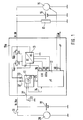
- FIG. 1 shows the configuration of an on-board electrical system control device shown for a two-battery electrical system that the On-board electrical system power supply even when the on-board electrical system battery is empty ensures optimal and gentle loading of both Batteries guaranteed.
- the on-board electrical system control unit 10a consists of a Supply power supply 11, a control and regulating unit 12, e.g. is designed as a bus-compatible microcomputer, a DC converter 13 and a short-circuit proof Power stage 14a, 14b.
- the vehicle electrical system control unit 10a is included its power-side inputs to terminals terminals 30 and Terminal 30a connected.
- terminal 30 is common Way the generator 15, the battery 16, the Supply battery for the vehicle electrical system (vehicle electrical system battery) represents and the load 17 connected.
- the load is 17 representative of the multitude of On-board electrical system consumers specified, the consumers in each case can be switched on via switches, not shown.
- the battery 18 is connected to the terminal 30a is designed as a starter battery and when closed Switch 19 is used to supply starter 20.
- the control unit 10a and the control and regulating unit 12 have a number of inputs and outputs that the Connection to the individual components of the Establish the onboard power supply control unit or the other onboard power supply.
- One of these inputs is designated 21, it serves the Initialization and leads from the power supply 11 to the Switch 22. If this switch 22 is closed, the Field effect transistor 23 of supply power supply 11 connected through. Via a connection 24 between the Power supply unit 11 and the control and regulating unit 12 can the field effect transistor 23 also from the control and Control unit 12 are initialized.
- the Power supply to the control unit 12 from the Supply power supply 11 takes place via connection 25.
- the control and regulating unit 12, or the associated one Microcomputer has further connections 26, 27, 28, 29, 30 and 31, about the information regarding the Switching state of the output stages 14, with respect to the Terminals Cl. 30 and Cl. 30a prevailing voltages U30 and U30a can be fed. Via the port 29 can Control signals are sent to the DC / DC converter 13 become.
- An influence on the Generator 50 possible and connection 31 provides one bidirectional connection for a bus, for example one CAN bus or a body bus. About these connections data or control signals can be exchanged a generator regulation taking into account Operating conditions of the internal combustion engine and one Internal combustion engine regulation taking into account Enable wiring system conditions.
- the power supply 11 of the control device 10 is connected to the two diodes 32, 33, the anode of which is connected to the terminal 30 or terminal 30a, without any further intermediate switch via the field-effect transistor 23 on both batteries.
- the vehicle electrical system control unit 10 is in a “sleep mode” in this state. In this operating state, the current consumption is only a few ⁇ amperes and is therefore below the range of battery self-discharge. The continuous current consumption is therefore negligible.
- the field effect transistor 23 of the Supply power supply 11 switched through and Total supply of the vehicle electrical system control unit 10a activated.
- the control and Control device 12 is the microcomputer first Voltage level on the vehicle electrical system side, i.e. at terminal 30 checked.
- the control and regulating device voltage U30 is fed to the input.
- the vehicle electrical system control unit 10a then waits for the Information that the start has been made. Come this Information not within a given time of for example 30 sec, the total power supply disabled.
- the field effect transistor 23 in Supply power supply 11 is controlled by the Microcomputer switched in a locked state and that Onboard power supply control unit 10a returns to "sleep mode".
- this body bus is also to the microcomputer of the vehicle electrical system control unit connected. From those that can be fed via the body bus Information regarding the outside temperature, the Cooling water temperature or the engine temperature and the Indoor temperature can be controlled by skillful Links the temperatures of the two batteries determine without these temperatures measured yourself should be. Because the battery temperature for the Voltage regulation is an essential quantity, it should be the setting of the target voltage must be taken into account. The Specification of the temperature-dependent charging voltage for the On-board electrical system battery 16 then takes place via a setpoint specification, which is fed to the generator controller.
- the battery 18 provided for the starter supply can as required via a DC / DC converter from the Vehicle electrical system side are supplied so that the temperature is adjusted both a higher and a lower or the same Charging voltage level compared to the vehicle electrical system voltage can be realized.
- the use of a suitable Voltage converter also allows one Charge the starter battery when the on-board electrical system battery is relatively heavily discharged.
- a starter battery Battery used the characteristics of which are specific to the Requirements, such as providing a short-term high current is adjusted.
- Figure 1 can be in the Case in which the vehicle electrical system voltage has dropped too far, accomplish another emergency operation. Will after the Initialization phase and query of the vehicle electrical system voltage recognized that this is a minimum predetermined Falls below the voltage level, the emergency operation triggered. To do this, when falling below the specified Voltage levels of both batteries 16 and 18 from Onboard power supply control unit connected in parallel and so that is On-board electrical system also supplied from the starter battery 16. At the same time, a message is sent Emergency operation information so that consumers are aware of their upstream electronic switches if necessary can be switched off, taking into account that only consumers that are not switched off are function or safety relevant. In addition can an error memory located on the on-board electrical system side can be set or an ad can be triggered.
- the power supply for the Vehicle electrical system control unit 10a interrupted if within the predeterminable time no start has taken place. Then it will be the Batteries 16, 18 separated again and the control unit 10 goes over to sleep mode until by closing the mechanical Switch 22 a new switch-on request is triggered.
- the engine takes Generator 15 does its work in the usual way and the Vehicle electrical system voltage increases after a relatively short time based on the current supplied by the generator. Reached the vehicle electrical system voltage is the defined threshold, we the Parallel connection of the two batteries canceled again, the control pulse required for this from the control and control device 12 is triggered. After opening the Connection between the two batteries 16 and 18 will be this according to the procedure described under point 1 charged, the battery 18 for supplying the starter 20 loading priority, so even after a short time Driving operation sufficient for a subsequent start Energy is available.
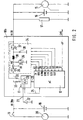
- FIG. 2 is a second embodiment of the invention shown, in which the short-circuit-proof output stage and Voltage converter according to the exemplary embodiment according to FIG. 1 is replaced by a power unit with converter 34.
- This Power section with converter consists of the Field effect transistors 35, 36 and 37, the inductance 38, which acts as a choke, and the freewheeling diode 39. Between the power section with converter 34 and the microcomputer of Control and regulating part 12 are different connections available, some of the connections according to 1 correspond to the exemplary embodiment. Same Components have the designations known from FIG. 1. Additional connections or connections 41, 42, 43, 44, 45 are available via which the control and regulating device 12 Information regarding the supply current IV and the Voltage UME can be supplied. The supply current IV is measured between transistor 35 and inductance 38, the voltage UME at the point ME. Control signals S35, S36, S37 to the transistors 35, 36 and 37 are connected to the Connections or connections 43, 44 and 45 issued.
- the electrical system control unit 10b shown in FIG. 2 basically works in normal operation according to the same principle as the electrical system control unit 10a according to FIG. 1.
- the operation of the electrical system control unit according to FIG. 2 in emergency operation can be described as follows: If the evaluation of the vehicle electrical system voltage after the initialization phase leads to the result that it is smaller than a predeterminable minimum value, the vehicle electrical system control unit 10a switches the two batteries 16 and 18 in parallel and the vehicle electrical system is also supplied via the starter battery 18. In this case, transistor 35 and transistor 37 are conductive, while transistor 36 is blocked.
- the system is switched to normal operation with a voltage increase, which causes the voltage U30a to be greater than U30.
- the transistor 37 is then turned on, the transistors 35 and 36 then clock in push-pull operation.
- the transistor 37 is operated in a clocked manner.
- Transistor 36 turns off and transistor 35 turns on.
- the two embodiments of the invention were for a Vehicle electrical system selected. Basically, one can Vehicle electrical system control device according to the invention also in others Use two-battery supply systems. Also one Expansion to more than two batteries is essential possible.
Landscapes
- Engineering & Computer Science (AREA)
- Power Engineering (AREA)
- Control Of Charge By Means Of Generators (AREA)
- Charge And Discharge Circuits For Batteries Or The Like (AREA)
- Direct Current Feeding And Distribution (AREA)
Description
Die Erfindung geht aus von einem Steuergerät für ein Bordnetz, insbesonders ein Fahrzeugbordnetz mit wenigstens zwei von einem Generator aufladbaren Batterien, nach der Gattung des Hauptanspruchs.The invention relates to a control unit for Vehicle electrical system, in particular a vehicle electrical system with at least two batteries rechargeable by a generator, after which Genus of the main claim.
Die Spannungsversorgung in einem Kraftfahrzeug mit einer Vielzahl von elektrischen Verbrauchern läßt sich mit Hilfe einer Batterie teilweise nicht mehr bewerkstelligen, so daß Fahrzeugbordnetze zunehmend mit zwei getrennten Batterien ausgestattet werden, die über geeignete elektronische Schaltungen miteinander verbindbar sind. Ein solches Fahrzeugbordnetz ist beispielsweise aus der DE-PS 41 38 943 bekannt.The voltage supply in a motor vehicle with a Many electrical consumers can be used with the help partially fail to accomplish a battery, so that Vehicle electrical systems increasingly with two separate batteries be equipped with suitable electronic Circuits are interconnectable. Such one Vehicle electrical system is for example from DE-PS 41 38 943 known.
Bei diesem bekannten Fahrzeugbordnetz ist eine erste Batterie überwiegend zur Versorgung des Starters vorgesehen, während die zweite Batterie zur Versorgung der übrigen Verbraucher dient. Die beiden Batterien können mit Hilfe eines sogenannten Lade-/Trennmoduls miteinander verbunden oder voneinander getrennt werden, wobei die Verbindung in Abhängigkeit von vorgebbaren Bedingungen vom Lade/Trennmodul geöffnet oder geschlossen wird. Die Spannungsversorgung für das Lade-/Trennmodul erfolgt aus den beiden Batterien.In this known vehicle electrical system is a first Battery mainly intended to supply the starter, while the second battery to power the rest Serves consumers. The two batteries can with the help a so-called charging / separation module connected to each other or be separated from one another, the connection in Dependency of predefinable conditions on the loading / disconnecting module is opened or closed. The Power supply for the charging / disconnecting module comes from the two batteries.
Das erfindungsgemäße Steuergerät für ein Bordnetz mit den
Merkmalen des Anspruchs 1 hat den Vorteil, daß es
kontinuierlich mit den zur Versorgung dienenden Batterien in
Verbindung steht, wobei die Stromaufnahme in deaktiviertem
Zustand minimal ist und nach Betätigung des Zündschalters
eine sehr schnelle und einfache Aktivierung des
Steuergerätes erfolgen kann.The control device according to the invention for an electrical system with the
Features of
Erzielt wird dieser Vorteil, indem das Steuergerät über ein Versorgungsnetzteil, das wenigstens einen Feldeffekttransistor umfaßt und über je eine Diode mit den Batterien in Verbindung steht und der Feldeffekttransistor während des Betriebes des Steuergerätes über ein zugeführtes Signal durchgeschaltet wird, so daß das Steuergerät dann direkt mit den Batterien in Verbindung steht, während im ausgeschalteten Zustand der Feldeffekttransistor gesperrt bleibt und das Steuergerät in einer Art "Sleep-Modus" betrieben wird, in dem es nur eine sehr geringe Stromaufnahme aufweist.This advantage is achieved by using the control unit via a Power supply that has at least one Field effect transistor includes and via a diode with each Batteries is connected and the field effect transistor during the operation of the control unit via a supplied Signal is switched through, so that the control unit then is directly connected to the batteries, while in off state of the field effect transistor locked remains and the control unit in a kind of "sleep mode" is operated in which there is only a very small Has current consumption.
Weitere Vorteile der Erfindung werden durch die in den Unteransprüchen angegebenen Maßnahmen erzielt. Dabei ist besonders vorteilhaft, daß mit Hilfe des erfindungsgemäßen Steuergerätes eine sehr variable Ausgestaltung der Bordnetzstruktur möglich ist. Bei Verwendung eines busfähigen Mikrocomputers im Steuergerät läßt sich ein Informationsaustausch zum Bordnetz realisieren. Dieser Informationsaustausch kann sich in vorteilhafter Weise auch auf den Informationsaustausch mit dem eigentlichen Steuergerät der Brennkraftmaschine erstrecken, so daß bei der Spannungsregelung Betriebsbedingungen der Brennkraftmaschine mitberücksichtigt werden können, beispielsweise Drehzahl, Leerlaufdrehzahl oder Last. Gleichzeitig kann das Steuergerät, das die Brennkraftmaschine regelt, generator- oder bordnetztypische Größen mitberücksichtigen.Further advantages of the invention are shown in the Measures specified in subclaims achieved. It is particularly advantageous that with the help of the invention Control unit a very variable configuration of the Wiring system structure is possible. When using a bus-compatible microcomputers in the control unit can be Realize information exchange to the electrical system. This Information exchange can also be advantageous on the exchange of information with the actual Extend control unit of the internal combustion engine, so that at the voltage regulation operating conditions of the Internal combustion engine can be taken into account, for example speed, idle speed or load. At the same time, the control unit that the Internal combustion engine controls, typical of generator or on-board network Take sizes into account.
Weiterhin ist vorteilhaft, daß bei der Generatorregelung die Temperatur der Batterien mitberücksichtigt werden kann, wobei-sich diese Temperatur in vorteilhafter Weise mittels einer_Beobachterfunktion aus einfach meßbaren Größen ermitteln läßt. Die Beeinflussung beider Ladespannungen ist somit durch das Bordnetzsteuergerät möglich.It is also advantageous that the generator control Temperature of the batteries can be taken into account, this temperature is advantageously controlled by means of an observer function from easily measurable quantities can be determined. The influencing of both charging voltages is thus possible through the onboard power supply control unit.
Die Parallelschaltung der beiden Batterien erfolgt in vorteilhafter Weise mittels Halbleiterschalter, wobei Power-MOSFET's besonders geeignet sind.The two batteries are connected in parallel in advantageously by means of semiconductor switches, wherein Power MOSFETs are particularly suitable.
Die für den Starter vorgesehene Batterie wird in vorteilhafter Weise bedarfsgerecht über einen Gleichspannungswandler von der Bordnetzseite her versorgt. Unterschreitet das Spannungsniveau einer der beiden Batterien einen vorgebbaren Wert, läßt sich ein Notbetrieb durchführen, bei dem die Starterbatterie aus der anderen Batterie über einen Gleichspannungswandler soweit geladen werden kann, daß ein Neustart gewährleistet ist. Durch Einsatz eines auf der Bordnetzseite befindlichen Fehlerspeichers können Notbetriebsinformationen abgespeichert werden, die beim Neustart oder beim nächsten Werkstattbesuch angezeigt werden und der Betriebszustand des Steuergerätes falls erforderlich in den Ruhemodus ("Sleep-Modus")zurückgesetzt werden. The battery intended for the starter is in advantageously in line with your needs DC voltage converter supplied from the vehicle electrical system side. If the voltage level falls below one of the two Batteries a predeterminable value, can be an emergency operation Carry out the starter battery from the other Battery so far charged via a DC converter can ensure that a restart is guaranteed. By Use of one located on the electrical system side Fault memory can provide emergency operating information be saved when restarting or next Visits to the workshop and the operating status of the If necessary, the control unit is reset to the sleep mode become.
Zwei Ausführungsbeispiele der Erfindung sind in den Figuren 1 und 2 der Zeichnung dargestellt und werden in der nachfolgenden Beschreibung näher erläutert.Two embodiments of the invention are in the figures 1 and 2 of the drawing and are shown in the following description explained in more detail.
In Figur 1 ist die Ausgestaltung eines Bordnetzsteuergerätes für ein Zwei-Batterien-Bordnetz dargestellt, das die Bordnetzenergieversorgung auch bei leerer Bordnetzbatterie sicherstellt sowie eine optimale und schonende Ladung beider Batterien gewährleistet.FIG. 1 shows the configuration of an on-board electrical system control device shown for a two-battery electrical system that the On-board electrical system power supply even when the on-board electrical system battery is empty ensures optimal and gentle loading of both Batteries guaranteed.
Im einzelnen besteht das Bordnetz-Steuergerät 10a aus einem
Versorgungsnetzteil 11, einer Steuer- und Regeleinheit 12,
die z.B. als busfähiger Mikrocomputer ausgestaltet ist,
einem Gleichspannungswandler 13 und einer kurzschlußsicheren
Endstufe 14a, 14b. Das Bordnetzsteuergerät 10a ist mit
seinen leistungsseitigen Eingängen an die Klemmen Kl. 30 und
Kl. 30a angeschlossen. An die Klemme Kl. 30 ist in üblicher
Weise der Generator 15, die Batterie 16, die die
Versorgungsbatterie für das Bordnetz (Bordnetzbatterie)
darstellt sowie die Last 17 angeschlossen. Die Last 17 ist
dabei stellvertretend für die Vielzahl der
Bordnetzverbraucher angegeben, wobei die Verbraucher jeweils
über nicht dargestellte Schalter zugeschaltet werden können.In detail, the on-board electrical
An die Klemme Kl. 30a ist die Batterie 18 angeschlossen, die
als Starterbatterie ausgestaltet ist und bei geschlossenem
Schalter 19 zur Versorgung des Starters 20 dient. The
Das Steuergerät 10a sowie die Steuer- und Regeleinheit 12
weisen eine Anzahl von Ein- bzw. Ausgängen auf, die die
Verbindung zu den einzelnen Komponenten des
Bordnetzsteuergerätes bzw. zum übrigen Bordnetz herstellen.
Einer dieser Eingänge ist mit 21 bezeichnet, er dient der
Initialisierung und führt vom Versorgungsnetzteil 11 auf den
Schalter 22. Wird dieser Schalter 22 geschlossen, wird der
Feldeffekttransistor 23 des Versorgungsnetzteiles 11
durchgeschaltet. Über eine Verbindung 24 zwischen dem
Versorgungsnetzteil 11 und der Steuer- und Regeleinheit 12
kann der Feldeffekttransistor 23 auch von der Steuer- und
Regeleinheit 12 initialisiert werden. Die
Spannungsversorgung der Steuer- und Regeleinheit 12 aus dem
Versorgungsnetzteil 11 erfolgt über die Verbindung 25.The
Die Steuer- und Regeleinheit 12, bzw. der zugehörige
Mikrocomputer weist weitere Anschlüsse 26, 27, 28, 29, 30
und 31 auf, über die Informationen bezüglich des
Schaltzustandes der Endstufen 14, bezüglich der an den
Klemmen Kl. 30 und Kl. 30a herrschenden Spannungen U30 und
U30a zugeführt werden können. Über den Anschluß 29 können
Steuersignale an den Gleichspannungswandler 13 abgesetzt
werden. Über den Anschluß 30 ist eine Beeinflussung des
Generators 50 möglich und Anschluß 31 stellt einen
bidirektionalen Anschluß für einen Bus, beispielsweise einen
CAN-Bus bzw. einen Karosseriebus. Über diese Anschlüsse
können Daten oder Steuersignale ausgetauscht werden, die
eine Generatorregelung unter Berücksichtigung von
Betriebsbedingungen der Brennkraftmaschine und eine
Brennkrftmaschinenregelung unter Berücksichtigung von
Bordnetzbedingungen ermöglichen.The control and regulating
Die Funktion des Ausführungsbeispieles nach Figur 1 läßt sich wie folgt erläutern: The function of the embodiment of Figure 1 leaves are explained as follows:
Das Netzteil 11 des Steuergerätes 10 liegt über die beiden
Dioden 32, 33, deren Anode jeweils an die Klemme Kl. 30 bzw.
Kl. 30a angeschlossen ist, ohne weiteren Zwischenschalter
über den Feldeffekttransistor 23 an beiden Batterien. Das
Bordnetzsteuergerät 10 befindet sich in diesem Zustand in
einem "Sleep-Modus". In diesem Betriebszustand beträgt die
Stromaufnahme nur wenige µ Ampère und liegt damit unter dem
Bereich der Batterieselbstentladung. Die Dauerstromaufnahme
ist somit vernachlässigbar klein.The
Über einen mechanischen Kontakt, beispielsweise im
Zündschloß nach Masse oder nach Klemme Kl. 30a, symbolisiert
durch den Schalter 22, wird der Feldeffekttransistor 23 des
Versorgungsnetzteiles 11 durchgeschaltet und die
Gesamtversorgung des Bordnetzsteuergerätes 10a aktiviert.
Nach dem Hochbuten des Mikrocomputers der Steuer- und
Regeleinrichtung 12 wird vom Mikrocomputer zuerst die
Spannungslage auf der Bordnetzseite, also an Klemme Kl. 30
überprüft. Dazu wird der Steuer- und Regeleinrichtung über
den Eingang die Spannung U30 zugeführt. Liegen diese
Spannungen oberhalb eines programmierbaren Wertes von
beispielsweise 11,8 V, so bleiben beide Batteriekreise
getrennt. Das Bordnetzsteuergerät 10a wartet dann auf die
Information, daß der Start erfolgt ist. Kommt diese
Information nicht innerhalb einer vorgebbaren Zeit von
beispielsweise 30 sec, wird die Gesamtstromversorgung
deaktiviert. Der Feldeffekttransistor 23 im
Versorgungsnetzteil 11 wird dabei durch Ansteuerung vom
Mikrocomputer in gesperrtem Zustand umgeschaltet und das
Bordnetzsteuergerät 10a geht in den "Sleep-Modus" zurück.Via a mechanical contact, for example in
Ignition lock to earth or to terminal 30a, symbolized
by the
Ein erneutes Aktivieren des Bordnetzsteuergerätes ist danach
nur durch erneutes Betätigen des mechanischen Schalters 22
möglich, beispielsweise indem der Zündschlüssel
herausgenommen und wieder eingesteckt wird.It is then necessary to reactivate the onboard power supply control unit
only by pressing the
Nach einem erfolgreichen Start des Motors werden die für
eine optimale Spannungsregelung erforderlichen Größen unter
Ausnutzung der von einzelnen Sensoren gelieferten oder im
Motorsteuergerät ohnehin vorhandenen Informationen
ermittelt. In einem Bordnetzsystem, das über ein
Karosseriebussystem verfügt, wird dieser Karosseriebus auch
an den Mikrocomputer des Bordnetzsteuergerätes
angeschlossen. Aus den über den Karosseriebus zuführbaren
Informationen bezüglich der Außentemperatur, der
Kühlwassertemperatur oder der Motortemperatur sowie der
Innenraumtemperatur lassen sich durch geschickte
Verknüpfungen die Temperaturen der beiden Batterien
ermitteln, ohne daß diese Temperaturen selbst gemessen
werden müßten. Da die Batterietemperatur für die
Spannungsregelung eine wesentliche Größe ist, sollte sie bei
der Festlegung der Sollspannung berücksichtigt werden. Die
Vorgabe der temperaturabhängigen Ladespannung für die
Bordnetzbatterie 16 erfolgt dann über eine Sollwertvorgabe,
die dem Generatorregler zugeführt wird.After a successful start of the engine, the for
an optimal voltage regulation required sizes below
Utilization of those supplied by individual sensors or in
Engine control unit information already available
determined. In an electrical system that has a
Body bus system, this body bus is also
to the microcomputer of the vehicle electrical system control unit
connected. From those that can be fed via the body bus
Information regarding the outside temperature, the
Cooling water temperature or the engine temperature and the
Indoor temperature can be controlled by skillful
Links the temperatures of the two batteries
determine without these temperatures measured yourself
should be. Because the battery temperature for the
Voltage regulation is an essential quantity, it should be
the setting of the target voltage must be taken into account. The
Specification of the temperature-dependent charging voltage for the
On-board
Damit die gegenüber höheren Spannungen empfindlichen Verbraucher geschützt werden, sollten in Bordnetzen, in denen für einzelne Verbraucher unterschiedliche Spannungen zur Verfügung gestellt werden, elektronische Schalter, DC/DC-Wandler usw. eingesetzt werden, die beispielsweise die Lampen schützen. Diese elektronischen Schalter bzw. DC/DC-Wandler werden vorteilhafterweise an verschiedenen Stellen des Bordnetzes eingesetzt, so daß die jeweils dahinterliegenden Verbraucher geschützt sind.So that the sensitive to higher voltages Consumers should be protected in vehicle electrical systems, in different voltages for individual consumers be provided, electronic switches, DC / DC converter, etc. are used, for example the Protect lamps. These electronic switches or DC / DC converters are advantageously used on different Set the electrical system used, so that each underlying consumers are protected.
Die für die Starterversorgung vorgesehene Batterie 18 kann
bedarfsgerecht über einen DC/DC-Wandler von der
Bordnetzseite her so versorgt werden, daß temperaturangepaßt
sowohl ein höheres als auch ein niedrigeres oder das selbe
Ladespannungsniveau im Vergleich zur Bordnetzspannung
realisiert werden kann. Der Einsatz eines geeigneten
Spannungswandlers ermöglicht im übrigen auch noch eine
Ladung der Starterbatterie, wenn die Bordnetzbatterie
relativ stark entladen ist. Als Starterbatterie wird eine
Batterie eingesetzt, deren Kenndaten speziell an die
Erfordernisse, beispielsweise Bereitstellung eines
kurzzeitigen hohen Stromes angepaßt ist.The
Mit dem Ausführungsbeispiel nach Figur 1 läßt sich in dem
Fall, in dem die Bordnetzspannung zu weit abgesunken ist,
noch ein Notbetrieb bewerkstelligen. Wird nach der
Initialisierungsphase und Abfrage der Bordnetzspannung
erkannt, daß diese ein minimales vorgegebenes
Spannungsniveau unterschreitet, wird der Notbetrieb
ausgelöst. Dazu werden beim Unterschreiten des vorgegebenen
Spannungsniveaus beide Batterien 16 und 18 vom
Bordnetzsteuergerät parallelgeschaltet und somit wird das
Bordnetz aus der Starterbatterie 16 mitversorgt.
Gleichzeitig erfolgt die Übermittlung einer
Notbetriebsinformation, so daß die Verbraucher über deren
vorgeschaltete elektronische Schalter gegebenenfalls
abgeschaltet werden können, wobei berücksichtigt wird, daß
nur solche Verbraucher abgeschaltet werden, die nicht
funktions- bzw. sicherheitsrelevant sind. Zusätzlich kann
dabei ein auf der Bordnetzseite befindlicher Fehlerspeicher
gesetzt werden oder es kann eine Anzeige ausgelöst werden.With the embodiment of Figure 1 can be in the
Case in which the vehicle electrical system voltage has dropped too far,
accomplish another emergency operation. Will after the
Initialization phase and query of the vehicle electrical system voltage
recognized that this is a minimum predetermined
Falls below the voltage level, the emergency operation
triggered. To do this, when falling below the specified
Voltage levels of both
Auch im Notbetrieb wird die Spannungsversorgung für das
Bordnetzsteuergerät 10a unterbrochen, wenn innerhalb der
vorgebbaren Zeit kein Start erfolgt ist. Es werden dann die
Batterien 16, 18 wieder getrennt und das Steuergerät 10 geht
in den Ruhemodus über, bis durch Schließen des mechanischen
Schalters 22 eine neue Einschaltanforderung ausgelöst wird.The power supply for the
Vehicle electrical
Erfolgt im Notbetrieb ein Start des Motors, nimmt der
Generator 15 in üblicher Weise seine Arbeit auf und die
Bordnetzspannung steigt nach einer relativ kurzen Zeit
aufgrund des vom Generator gelieferten Stromes an. Erreicht
die Bordnetzspannung die festgelegte Schwelle, wir die
Parallelschaltung der beiden Batterien wieder aufgehoben,
wobei der dazu erforderliche Ansteuerimpuls von der Steuer-
und Regeleinrichtung 12 ausgelöst wird. Nach Öffnen der
Verbindung zwischen den beiden Batterien 16 und 18 werden
diese gemäß dem unter Punkt 1 beschriebenen Verfahren
geladen, wobei die Batterie 18 zur Versorgung des Starters
20 Ladepriorität erhält, damit auch nach einem kurzzeitigen
Fahrbetrieb für einen nachfolgenden Start wieder genügend
Energie zur Verfügung steht.If the engine is started in emergency mode, the engine takes
In Figur 2 ist ein zweites Ausführungsbeispiel der Erfindung
dargestellt, bei dem die kurzschlußsichere Endstufe und der
Spannungswandler gemäß dem Ausführungsbeispiel nach Figur 1
durch ein Leistungsteil mit Wandler 34 ersetzt ist. Dieses
Leistungsteil mit Wandler besteht aus den
Feldeffekttransistoren 35, 36 und 37, der Induktivität 38,
die als Drossel wirkt, sowie der Freilaufdiode 39. Zwischen
dem Leistungsteil mit Wandler 34 und dem Mikrocomputer des
Steuer- und Regelteils 12 sind verschiedene Verbindungen
vorhanden, die teilweise den Verbindungen gemäß dem
Ausführungsbeispiel nach Figur 1 entsprechen. Gleiche
Bauteile weisen die aus Fig. 1 bekannten Bezeichnungen auf.
Zusätzliche Verbindungen bzw. Anschlüsse 41, 42, 43, 44, 45
sind vorhanden, über die der Steuer- und Regeleinrichtung 12
Informationen bezüglich des Versorgungsstroms IV und der
Spannung UME zugeführt werden. Der Versorgungsstrom IV wird
zwischen dem Transistor 35 und der Induktivität 38 gemessen,
die Spannung UME am Punkt ME. Ansteuersignale S35, S36, S37
an die Transistoren 35, 36 und 37 werden über die
Verbindungen bzw. Anschlüsse 43, 44 und 45 abgegeben.In Figure 2 is a second embodiment of the invention
shown, in which the short-circuit-proof output stage and
Voltage converter according to the exemplary embodiment according to FIG. 1
is replaced by a power unit with
Das in Figur 2 dargestellte Bordnetzsteuergerät 10b
funktioniert im Normalbetrieb grundsätzlich nach dem
gleichen Prinzip wie das Bordnetzsteuergerät 10a nach Figur
1. Die Funktionsweise des Bordnetzsteuergerätes nach Figur 2
im Notbetrieb läßt sich wie folgt beschreiben:
Führt die Auswertung der Bordnetzspannung nach der
Initialisierungsphase zu dem Ergebnis, daß sie kleiner ist
als ein vorgebbarer Minimalwert, schaltet das
Bordnetzsteuergerät 10a die beiden Batterien 16 und 18
parallel und das Bordnetz wird über die Starterbatterie 18
mitversorgt. In diesem Fall ist der Transistor 35 und der
Transistor 37 leitend, während der Transistor 36 gesperrt
ist. Übersteigt die Bordnetzspannung nach Anlaufen des
Motors und damit nach Stromabgabe durch den Generator 15 das
vorgegebene Spannungsniveau, wird auf Normalbetrieb
umgeschaltet mit einer Spannungserhöhung, die bewirkt, daß
die Spannung U30a größer ist als U30. Es wird dann der
Transistor 37 leitend geschaltet, die Transistoren 35 und 36
takten dann im Gegentaktbetrieb. Bei einer
Spannungserniedrigung, bei der die Spannung U30a kleiner ist
als die Spannung U30 wird der Transistor 37 getaktet
betrieben. Der Transistor 36 sperrt und der Transistor 35
wird eingeschaltet.The electrical
If the evaluation of the vehicle electrical system voltage after the initialization phase leads to the result that it is smaller than a predeterminable minimum value, the vehicle electrical
Da das Ausführungsbeispiel nach Figur 2 mit einer in Serie
geschalteten Drossel ausgestattet ist, die den Stromanstieg
verzögert, ist kein zusätzlicher Überlastschutz im
Leistungsteil mit Wandler nötig. Der Stromanstieg wird durch
die Drossel 30 soweit verzögert, daß der Mikrocomputer der
Steuer- und Regeleinrichtung 12 innerhalb seiner Taktzeit
reagieren kann und somit einen Überlastschutz gewährleisten
kann. Die Strommessung kann durch eine direkte
Stromerfassung über einen Shunt oder über eine Auswertung
des Spannungsverlaufs von UDS oder über ein zeitlich
begrenztes Einschalten des jeweiligen Feldeffekttransistors
35 oder 37 und Beobachtung der Spannung an der Klemme Kl. 30
bzw. Kl. 30a erfolgen. Der Transistor 37 kann gleichzeitig
als Schalter für den Gleichspannungswandler dienen, so daß
als DC/DC-Wandler ein Hoch-Tiefsetzsteller erhalten wird und
zur Parallelschaltung der beiden Batterien 16, 18 verwendet
wird.Since the embodiment of Figure 2 with one in series
switched choke, which is the current rise
delayed, there is no additional overload protection in the
Power section with converter required. The current rise is through
the
Die beiden Ausführungsbeispiele der Erfindung wurden für ein Fahrzeugbordnetz ausgewählt. Grundsätzlich läßt sich ein erfindungsgemäßes Bordnetzsteuergerät auch in anderen Zweibatterie-Versorgungssystemen einsetzen. Auch eine Erweiterung auf mehr als zwei Batterien ist grundsätzlich möglich.The two embodiments of the invention were for a Vehicle electrical system selected. Basically, one can Vehicle electrical system control device according to the invention also in others Use two-battery supply systems. Also one Expansion to more than two batteries is essential possible.
Claims (6)
- Control device (10a, 10b) for a vehicle's electrical system having at least two batteries (16, 18) which can be charged by a generator (50) and which are used to supply first and second loads (17) and which are connected to one another via the control device (10a, 10b), the two batteries (16, 18) being connected only under predefinable conditions, characterized in that the control device (10a, 10b) comprises a power supply unit (11) having at least one field-effect transistor (23) and is connected to the batteries (16, 18) via voltage-limiting means (32, 33), and the field-effect transistor (23) is connected through by feeding in a signal in order to activate the control device (10a, 10b).
- Control device for a vehicle's electrical system according to Claim 1, characterized in that an open-loop and closed-loop control unit (12), which comprises a microcomputer, is provided as a component of the control device (10a, 10b) and triggers the open-loop and closed-loop control processes.
- Control device for a vehicle's electrical system according to Claim 2, characterized in that information is fed to the open-loop and closed-loop control unit (12) via inputs, and the open-loop and closed-loop control unit (12) determines, as a function of this information, actuation signals which are output to individual components of the control device and/or of the vehicle's electrical system via connections.
- Control device for a vehicle's electrical system according to one of the preceding claims, characterized in that a d.c. voltage converter which can be actuated by the open-loop and closed-loop control unit can be connected in series between the two batteries (16) and (18).
- Control device for a vehicle's electrical system according to one of the preceding claims, characterized in that a power unit with converter is provided, which power unit is located in the connection between the two batteries (16) and (18) and outputs data to the control unit (12) and receives actuation signals from it.
- Control device according to Claim 5, characterized in that the power unit with converter comprises a series circuit composed of a first transistor (35), inductor (38) and second transistor (37), a further transistor (36) and a diode (39) being respectively located between each terminal of the inductor (38) and ground.
Applications Claiming Priority (3)
| Application Number | Priority Date | Filing Date | Title |
|---|---|---|---|
| DE19645944A DE19645944A1 (en) | 1996-11-07 | 1996-11-07 | Control unit for an electrical system |
| DE19645944 | 1996-11-07 | ||
| PCT/DE1997/002332 WO1998019890A1 (en) | 1996-11-07 | 1997-10-11 | Control unit for the power supply system on-board |
Publications (2)
| Publication Number | Publication Date |
|---|---|
| EP0935540A1 EP0935540A1 (en) | 1999-08-18 |
| EP0935540B1 true EP0935540B1 (en) | 2001-09-26 |
Family
ID=7810943
Family Applications (1)
| Application Number | Title | Priority Date | Filing Date |
|---|---|---|---|
| EP97945739A Expired - Lifetime EP0935540B1 (en) | 1996-11-07 | 1997-10-11 | Control unit for the power supply system on-board |
Country Status (6)
| Country | Link |
|---|---|
| US (1) | US6232674B1 (en) |
| EP (1) | EP0935540B1 (en) |
| JP (1) | JP4036901B2 (en) |
| DE (2) | DE19645944A1 (en) |
| ES (1) | ES2165094T3 (en) |
| WO (1) | WO1998019890A1 (en) |
Families Citing this family (98)
| Publication number | Priority date | Publication date | Assignee | Title |
|---|---|---|---|---|
| SE514786C2 (en) * | 1998-09-02 | 2001-04-23 | Scania Cv Ab | Electrical system for motor vehicles with dual batteries |
| DE19839997C1 (en) * | 1998-09-02 | 2000-06-21 | Siemens Ag | Electronic circuitry |
| DE19931144B9 (en) * | 1998-09-08 | 2013-02-07 | Volkswagen Ag | Method for operating an electrical vehicle electrical system |
| DE19903426A1 (en) | 1999-01-29 | 2000-08-03 | Bosch Gmbh Robert | Device and method for regulating a generator with an associated voltage converter |
| FR2790147B1 (en) * | 1999-02-19 | 2003-09-26 | Sagem | DEVICE FOR TRANSFERRING CHARGE CURRENT BETWEEN TWO BATTERIES |
| DE19913131B4 (en) * | 1999-03-23 | 2004-07-22 | Siemens Ag | Power supply system with two batteries of different voltages |
| US6879057B1 (en) | 1999-06-09 | 2005-04-12 | Lear Automotive (Eeds) Spain, S.L. | Electrical distribution box for vehicles having two networks with different voltage levels |
| DE19941481B4 (en) * | 1999-09-01 | 2009-07-09 | Robert Bosch Gmbh | Electrically controlled, decentralized control system in a vehicle |
| DE19941699A1 (en) * | 1999-09-02 | 2001-03-08 | Bosch Gmbh Robert | Semiconductor fuse for electrical consumers |
| DE19951128A1 (en) * | 1999-10-23 | 2001-04-26 | Bosch Gmbh Robert | Method and device for voltage regulation |
| DE19955721A1 (en) * | 1999-11-15 | 2001-05-17 | Volkswagen Ag | Two-battery system |
| DE19957477A1 (en) * | 1999-11-23 | 2001-05-31 | Volkswagen Ag | Motor vehicle electrical system |
| ES2164578B1 (en) * | 1999-12-24 | 2003-05-16 | Lear Automotive Eeds Spain | CONVERTER IN "INTERLEAVING" OF CONTINUOUS-CONTINUOUS ELECTRICAL ENERGY. |
| DE10008266A1 (en) | 2000-02-23 | 2001-08-30 | Bosch Gmbh Robert | Device for switching controller on and off has two electronic switches, each for separate supply voltage path, logic unit with signal combination unit between the inputs and outputs |
| JP2001327158A (en) * | 2000-05-12 | 2001-11-22 | Toyota Motor Corp | Power circuit of voltage converter |
| DE10028748B4 (en) * | 2000-06-10 | 2009-06-04 | Bayerische Motoren Werke Aktiengesellschaft | Power supply system for a motor vehicle with a low voltage electrical system and with a high voltage onboard power supply |
| FR2812474B1 (en) * | 2000-07-31 | 2004-06-18 | Valeo Climatisation | DEVICE FOR PROTECTING AN ELECTRIC SOURCE CAPABLE OF SUPPLYING AN ELECTRICAL MEMBER |
| US6455951B1 (en) * | 2000-08-16 | 2002-09-24 | Yazaki North America, Inc. | Auto charger for system including a high voltage supply and a low voltage supply |
| DE10100889B4 (en) * | 2001-01-11 | 2013-11-14 | Robert Bosch Gmbh | Method and device for realizing a start / stop operation in vehicles |
| DE10109796A1 (en) | 2001-03-01 | 2002-09-05 | Bosch Gmbh Robert | Circuit and method for specifying a start signal for a controller |
| JP3886741B2 (en) * | 2001-06-07 | 2007-02-28 | 三菱電機株式会社 | Power supply system for internal combustion engine controller |
| ES2300463T3 (en) | 2001-06-29 | 2008-06-16 | Robert Bosch Gmbh | DEVICE AND / OR PROCEDURE FOR THE DETERMINATION OF THE AVAILABILITY OF ELECTRICAL ENERGY, ESPECIALLY IN THE ONBOARD NETWORK WITH VARIOUS ENERGY ACCUMULATORS. |
| ES2181606B1 (en) * | 2001-08-08 | 2004-08-16 | Lear Automotive (Eeds) Spain, S.L. | SYSTEM AND METHOD OF ELECTRICAL DISTRIBUTION FOR A VEHICLE WITH TWO NETWORKS AT DIFFERENT VOLTAGE LEVELS. |
| EP1462315B1 (en) * | 2001-11-27 | 2007-02-21 | Lear Automotive (EEDS) Spain, S.L. | System and method for protecting against short circuits in electric power distribution architectures with two voltage levels |
| FR2833113B1 (en) * | 2001-11-30 | 2004-07-09 | Valeo Equip Electr Moteur | DIRECT DIRECT CURRENT TO REVERSIBLE DIRECT CURRENT FOR TWO-VOLTAGE NETWORK AND TWO-VOLTAGE NETWORK PROVIDED WITH SUCH A CONVERTER |
| US6437462B1 (en) * | 2001-12-10 | 2002-08-20 | Delphi Technologies, Inc. | Bi-directional DC/DC converter and control method therefor |
| ES2189696B1 (en) * | 2001-12-27 | 2004-11-16 | Lear Automotive (Eeds) Spain, S.L | MANAGEMENT SYSTEM OF A VEHICLE WITH DOUBLE BATTERY AND METHOD. |
| US6924621B2 (en) | 2002-05-07 | 2005-08-02 | C.E. Niehoff & Co. | System and method for controlling electric load and battery charge in a vehicle |
| US7236893B2 (en) | 2002-06-11 | 2007-06-26 | Daimlerchrysler Ag | Arrangement for voltage supply to several users and controllers for a on-board network comprising at least two energy stores |
| FR2848033B1 (en) * | 2002-12-03 | 2008-08-29 | Renault Sas | SYSTEM AND METHOD FOR TWO VOLTAGE POWER SUPPLY FOR VEHICLE. |
| DE10304764B3 (en) | 2003-02-05 | 2004-02-26 | Daimlerchrysler Ag | Dual-voltage onboard electrical network for automobile has 2 series batteries connected in parallel for emergency starting and used for providing emergency running upon failure of generator or DC/DC converter |
| US20070183109A1 (en) * | 2003-02-13 | 2007-08-09 | Poweready, Inc. | Safety circuit technique for high current shut-down |
| US7336002B2 (en) * | 2003-02-17 | 2008-02-26 | Denso Corporation | Vehicle power supply system |
| JP4120418B2 (en) * | 2003-02-17 | 2008-07-16 | 株式会社デンソー | Automotive power supply |
| US7614381B2 (en) * | 2003-03-28 | 2009-11-10 | Caterpillar Inc. | Power system with an integrated lubrication circuit |
| JP2004338577A (en) * | 2003-05-16 | 2004-12-02 | Hitachi Ltd | Power supply device and method for vehicle |
| DE10346325A1 (en) | 2003-10-06 | 2005-05-04 | Siemens Ag | Switching device for bidirectional charge equalization between energy stores |
| US7176585B2 (en) * | 2003-12-29 | 2007-02-13 | Temic Automotive Of North America, Inc. | Power distribution web node and power management process |
| US7157806B2 (en) * | 2004-03-12 | 2007-01-02 | C. E. Niehoff & Co. | System and method for controlling and distributing electrical energy in a vehicle |
| JP4211715B2 (en) * | 2004-08-23 | 2009-01-21 | 株式会社デンソー | In-vehicle power supply system |
| FR2879040B1 (en) * | 2004-12-03 | 2007-11-30 | Jean Paul Siaudeau | COUPLER OF BATTERIES |
| US7362005B2 (en) * | 2005-03-10 | 2008-04-22 | Red Tech Inc. | Isolated dual battery system |
| SE0500797L (en) * | 2005-04-08 | 2006-09-26 | Creator Teknisk Utveckling Ab | The battery charging system |
| IL169549A0 (en) * | 2005-07-06 | 2007-07-04 | Yeshua Rahamim Levi | A self report over a traffic felony |
| EP1772941B1 (en) * | 2005-10-10 | 2008-08-13 | C.R.F. Societa Consortile per Azioni | Motor vehicle electrical supply system |
| JP4449940B2 (en) * | 2006-05-16 | 2010-04-14 | トヨタ自動車株式会社 | Dual power supply system for vehicles |
| DE102006037125A1 (en) | 2006-08-09 | 2008-02-14 | Daimler Ag | Drive system for a drive unit of a motor vehicle |
| US20090033155A1 (en) * | 2007-06-08 | 2009-02-05 | Renesas Technology Corp. | Semiconductor integrated circuits |
| US9579961B2 (en) * | 2007-09-24 | 2017-02-28 | Scott C Harris | Hybrid vehicle with modular battery system |
| DE102007062955B4 (en) * | 2007-12-21 | 2011-06-01 | Catem Develec Gmbh & Co. Kg | Circuit for voltage stabilization of a vehicle electrical system |
| SE532001C2 (en) * | 2008-02-04 | 2009-09-22 | Scania Cv Abp | Electrical system for a motor vehicle and a method for controlling a starter motor and a battery disconnector in such an electrical system |
| AU2009239567A1 (en) * | 2008-04-21 | 2009-10-29 | International Truck Intellectual Property Company, Llc | Multiple battery system for a motor vehicle |
| US8076797B2 (en) * | 2008-05-15 | 2011-12-13 | Indy Power Systems Llc | Energy transfer circuit and method |
| US8295950B1 (en) | 2008-07-02 | 2012-10-23 | Jerry Lee Wordsworth | Intelligent power management system |
| EP2340596B1 (en) | 2008-10-17 | 2012-08-15 | Koninklijke Philips Electronics N.V. | Power control in a medical ventilator |
| DE102008054885B4 (en) * | 2008-12-18 | 2014-09-18 | Lisa Dräxlmaier GmbH | Device and method for controlling a power supply of a vehicle electrical system of a vehicle |
| JP2011004556A (en) * | 2009-06-22 | 2011-01-06 | Mitsubishi Electric Corp | Power supply device for vehicle |
| DE102009041872B4 (en) * | 2009-09-16 | 2014-10-30 | Hella Kgaa Hueck & Co. | Circuit arrangement for electrical system stabilization with a DC chopper |
| US20110084665A1 (en) * | 2009-10-09 | 2011-04-14 | Christopher White | Method and apparatus of stored energy management in battery powered vehicles |
| US8314587B2 (en) * | 2009-10-09 | 2012-11-20 | Alcatel Lucent | Method and apparatus of stored energy management in battery powered vehicles |
| US20130037531A1 (en) * | 2009-11-06 | 2013-02-14 | Rick Gray | Electrically heated garment |
| CA2720339C (en) | 2009-11-06 | 2017-09-26 | Milwaukee Electric Tool Corporation | Electrically heated garment |
| JP5234052B2 (en) * | 2010-04-27 | 2013-07-10 | 株式会社デンソー | Power supply |
| DE102010030160B4 (en) * | 2010-06-16 | 2023-10-12 | Bayerische Motoren Werke Aktiengesellschaft | Method and control device for processing data in a network of a vehicle |
| US8981710B2 (en) | 2010-09-20 | 2015-03-17 | Indy Power Systems Llc | Energy management system |
| DE102011101531B4 (en) * | 2011-05-14 | 2015-09-24 | Volkswagen Aktiengesellschaft | Motor vehicle electrical system and method for operating a motor vehicle electrical system |
| JP5488529B2 (en) * | 2011-05-17 | 2014-05-14 | マツダ株式会社 | Vehicle power supply control device |
| FR2975839B1 (en) * | 2011-05-23 | 2013-05-17 | Renault Sa | METHOD FOR RECHARGING A TORQUE OF VEHICLE BATTERIES OF DIFFERENT NOMINAL VOLTAGES, AND ASSOCIATED SYSTEM |
| JP5847506B2 (en) * | 2011-09-14 | 2016-01-20 | 株式会社ケーヒン | Electronic control device and vehicle control system |
| DE102011086829A1 (en) * | 2011-11-22 | 2013-05-23 | Continental Automotive Gmbh | On-board network and method for operating a vehicle electrical system |
| JP5477409B2 (en) | 2012-03-12 | 2014-04-23 | 株式会社デンソー | Power system |
| DE102012215374A1 (en) | 2012-08-30 | 2014-05-28 | Bayerische Motoren Werke Aktiengesellschaft | Reload function when not starting |
| US9580003B2 (en) * | 2012-10-01 | 2017-02-28 | Thermo King Corporation | Methods and systems for starting an electrically controlled engine of a transport refrigeration system |
| DE102012024652A1 (en) | 2012-12-17 | 2014-06-18 | Volkswagen Aktiengesellschaft | Motor vehicle, has a switch diode arrangement connected in parallel for the output of diagnostic data relating to the first energy storage device, through a bus interface such as a controller area network (CAN) bus interface |
| FR3001931A1 (en) * | 2013-02-14 | 2014-08-15 | Peugeot Citroen Automobiles Sa | Device for managing energy transfer from and towards electrical energy storage of motor vehicle, has managing unit for limiting voltage value and/or current value of electrical energy transfer |
| DE102013206298A1 (en) * | 2013-04-10 | 2014-10-16 | Robert Bosch Gmbh | Method for operating a multi-voltage vehicle electrical system, multi-voltage vehicle electrical system and means for implementing the method |
| JP5907118B2 (en) | 2013-05-22 | 2016-04-20 | 株式会社デンソー | Power supply system abnormality detection device |
| US9682672B2 (en) * | 2013-09-18 | 2017-06-20 | Flextronics Ap, Llc | Device and method for current flow control for dual battery vehicle architecture |
| DE102013219751A1 (en) * | 2013-09-30 | 2015-04-02 | Siemens Aktiengesellschaft | Method for operating a rail vehicle |
| US9812949B2 (en) | 2013-10-10 | 2017-11-07 | Indy Power Systems Llc | Poly-phase inverter with independent phase control |
| DE102013221043A1 (en) * | 2013-10-17 | 2015-04-23 | Bayerische Motoren Werke Aktiengesellschaft | emergency starting |
| CN103707772B (en) * | 2014-01-08 | 2016-04-06 | 上汽通用五菱汽车股份有限公司 | A kind of power-on and power-off control circuit of electronlmobil and method |
| JP6221796B2 (en) * | 2014-02-07 | 2017-11-01 | 株式会社デンソー | Battery unit and power supply system |
| JP6090195B2 (en) * | 2014-02-10 | 2017-03-08 | 株式会社デンソー | Battery unit |
| DE102014203030B4 (en) | 2014-02-19 | 2021-06-02 | Vitesco Technologies GmbH | Method for the controlled connection of several on-board network branches of a vehicle, control unit for executing the method and vehicle on-board network |
| USD808616S1 (en) | 2014-02-28 | 2018-01-30 | Milwaukee Electric Tool Corporation | Single control button for an article of clothing |
| US11033059B2 (en) | 2014-11-06 | 2021-06-15 | Milwaukee Electric Tool Corporation | Article of clothing with control button |
| JP6079760B2 (en) * | 2014-12-04 | 2017-02-15 | マツダ株式会社 | Vehicle power supply control device |
| DE102015214415A1 (en) | 2015-07-29 | 2017-02-02 | Robert Bosch Gmbh | Method and device for energy-saving operation of a control unit |
| FR3043281B1 (en) * | 2015-10-30 | 2017-12-08 | Peugeot Citroen Automobiles Sa | ACTIVE CONTROL DEVICE FOR ELECTRICAL CIRCUIT WITH DC / DC CONVERTER AND ELECTRICAL ENERGY STORER MOUNTED IN SERIES |
| DE102016101081A1 (en) * | 2016-01-22 | 2017-07-27 | Eberspächer Controls Landau Gmbh & Co. Kg | On-board network for a vehicle |
| JP6750288B2 (en) * | 2016-04-15 | 2020-09-02 | 株式会社オートネットワーク技術研究所 | Relay device |
| JP6748906B2 (en) | 2016-04-15 | 2020-09-02 | 株式会社オートネットワーク技術研究所 | Relay device |
| GB2574196B (en) | 2018-05-21 | 2022-08-24 | Bae Systems Plc | Supercapacitor arrangement for enhancing electronic power performance of waterborne vehicles |
| WO2020167755A1 (en) * | 2019-02-15 | 2020-08-20 | Kold-Ban International, Ltd. | Supplemental starting system |
| DE102020122508A1 (en) * | 2020-08-28 | 2022-03-03 | Knorr-Bremse Systeme für Nutzfahrzeuge GmbH | POWER SUPPLY DEVICE, METHOD OF POWERING AT LEAST AN ELECTRICAL CONSUMER AND VEHICLE |
| WO2022120161A1 (en) | 2020-12-04 | 2022-06-09 | Milwaukee Electric Tool Corporation | Electrically heated garment with pass-through battery pocket |
| USD1020226S1 (en) | 2021-10-21 | 2024-04-02 | Milwaukee Electric Tool Corporation | Control button for heated garment |
Family Cites Families (18)
| Publication number | Priority date | Publication date | Assignee | Title |
|---|---|---|---|---|
| WO1979000617A1 (en) * | 1978-02-13 | 1979-09-06 | D Pettersson | A battery separator |
| JPS5930643U (en) * | 1982-08-23 | 1984-02-25 | パイオニア株式会社 | charge/discharge circuit |
| GB2136224A (en) * | 1983-03-02 | 1984-09-12 | Ford Motor Co | Vehicle electrical system |
| JP2516327Y2 (en) * | 1989-07-20 | 1996-11-06 | 本田技研工業株式会社 | DC power supply |
| JPH0748934B2 (en) * | 1990-04-16 | 1995-05-24 | 日本電装株式会社 | Occupant protection device failure detection device |
| JP3189311B2 (en) * | 1990-09-05 | 2001-07-16 | 株式会社デンソー | Power supply for automotive electronic equipment |
| DE4028242C2 (en) * | 1990-09-06 | 1997-08-07 | Bayerische Motoren Werke Ag | Vehicle electrical system |
| DE4138943C1 (en) | 1991-11-27 | 1993-05-27 | Robert Bosch Gmbh, 7000 Stuttgart, De | |
| JP3039119B2 (en) * | 1992-03-31 | 2000-05-08 | 日産自動車株式会社 | Power supply for vehicles |
| US5316868A (en) * | 1992-07-21 | 1994-05-31 | Globe-Union, Inc. | Dual battery switch circuit |
| JP2941145B2 (en) * | 1993-06-01 | 1999-08-25 | 株式会社ピーエフユー | Power supply |
| US5488283A (en) * | 1993-09-28 | 1996-01-30 | Globe-Union, Inc. | Vehicle battery system providing battery back-up and opportunity charging |
| US5569997A (en) * | 1993-10-04 | 1996-10-29 | Ford Motor Company | Power supply for volatile memory devices and portable electrical appliance in vehicles |
| JP3014573B2 (en) * | 1993-11-04 | 2000-02-28 | 三菱電機株式会社 | Power supply voltage switching device for vehicles |
| US5481175A (en) * | 1993-12-20 | 1996-01-02 | Motorola, Inc. | System and method for charging auxiliary batteries |
| JPH07309210A (en) * | 1994-05-19 | 1995-11-28 | Nippondenso Co Ltd | Windshield heater for electric vehicle |
| JPH08132992A (en) * | 1994-11-10 | 1996-05-28 | Mitsubishi Electric Corp | On-vehicle controller |
| DE19530721A1 (en) * | 1995-08-18 | 1997-02-20 | Kiekert Ag | Control unit e.g. for motor vehicle electric windows, anti-theft warning and locks |
-
1996
- 1996-11-07 DE DE19645944A patent/DE19645944A1/en not_active Withdrawn
-
1997
- 1997-10-11 JP JP52093298A patent/JP4036901B2/en not_active Expired - Fee Related
- 1997-10-11 EP EP97945739A patent/EP0935540B1/en not_active Expired - Lifetime
- 1997-10-11 DE DE59704732T patent/DE59704732D1/en not_active Expired - Lifetime
- 1997-10-11 WO PCT/DE1997/002332 patent/WO1998019890A1/en active IP Right Grant
- 1997-10-11 US US09/284,306 patent/US6232674B1/en not_active Expired - Lifetime
- 1997-10-11 ES ES97945739T patent/ES2165094T3/en not_active Expired - Lifetime
Also Published As
| Publication number | Publication date |
|---|---|
| WO1998019890A1 (en) | 1998-05-14 |
| DE19645944A1 (en) | 1998-05-14 |
| ES2165094T3 (en) | 2002-03-01 |
| US6232674B1 (en) | 2001-05-15 |
| JP4036901B2 (en) | 2008-01-23 |
| JP2001503703A (en) | 2001-03-21 |
| EP0935540A1 (en) | 1999-08-18 |
| DE59704732D1 (en) | 2001-10-31 |
Similar Documents
| Publication | Publication Date | Title |
|---|---|---|
| EP0935540B1 (en) | Control unit for the power supply system on-board | |
| EP0568655B1 (en) | Device for supplying electric power in a motor vehicle | |
| DE102012222208B4 (en) | Method for the controlled connection of several on-board network branches of a vehicle, control unit for executing the method and on-board network | |
| DE102014203030B4 (en) | Method for the controlled connection of several on-board network branches of a vehicle, control unit for executing the method and vehicle on-board network | |
| EP2160813B1 (en) | Motor vehicle power supply system | |
| EP0850506B1 (en) | Device for supplying power in a motor vehicle | |
| EP2805396B1 (en) | Vehicle electric system | |
| EP1232073B1 (en) | Dual battery system | |
| DE102008054885B4 (en) | Device and method for controlling a power supply of a vehicle electrical system of a vehicle | |
| EP3022432B1 (en) | Electronic safety interruptor for motor vehicles | |
| EP3022433B1 (en) | Switch arrangement in motor vehicle electrical circuit | |
| EP2783442B1 (en) | Vehicle electrical system and method for operating a vehicle electrical system | |
| EP2822808B1 (en) | On-board power system for a vehicle | |
| EP1093974A2 (en) | Procedure and device for voltage regulation | |
| DE102010029788B4 (en) | Vehicle electrical system and method and device for operating the vehicle electrical system | |
| DE112017006219B4 (en) | Vehicle mounted power supply device | |
| WO2013160031A1 (en) | Motor vehicle onboard power supply system having at least two subnetworks | |
| DE69813862T2 (en) | METHOD AND DEVICE FOR CHARGING CONTROL IN AN ELECTRICAL SYSTEM WITH TWO BATTERIES | |
| EP1104719B1 (en) | Power supply for vehicles | |
| WO2017202537A1 (en) | Motor vehicle on-board system having at least two energy stores, method for operating a motor vehicle on-board system; and means for the implementation thereof | |
| DE10228350A1 (en) | On-board power supply to supply a high-performance consumer | |
| DE102018006582B4 (en) | Battery for a motor vehicle and vehicle electrical system | |
| DE102008012640A1 (en) | Device for coupling several subnetworks | |
| EP1318590B1 (en) | Power supply device with two batteries and two generators in a commercial vehicle | |
| EP1044852A2 (en) | Power supply network for vehicles |
Legal Events
| Date | Code | Title | Description |
|---|---|---|---|
| PUAI | Public reference made under article 153(3) epc to a published international application that has entered the european phase |
Free format text: ORIGINAL CODE: 0009012 |
|
| 17P | Request for examination filed |
Effective date: 19990607 |
|
| AK | Designated contracting states |
Kind code of ref document: A1 Designated state(s): DE ES FR GB IT SE |
|
| GRAG | Despatch of communication of intention to grant |
Free format text: ORIGINAL CODE: EPIDOS AGRA |
|
| 17Q | First examination report despatched |
Effective date: 20001128 |
|
| GRAG | Despatch of communication of intention to grant |
Free format text: ORIGINAL CODE: EPIDOS AGRA |
|
| GRAH | Despatch of communication of intention to grant a patent |
Free format text: ORIGINAL CODE: EPIDOS IGRA |
|
| GRAH | Despatch of communication of intention to grant a patent |
Free format text: ORIGINAL CODE: EPIDOS IGRA |
|
| GRAA | (expected) grant |
Free format text: ORIGINAL CODE: 0009210 |
|
| AK | Designated contracting states |
Kind code of ref document: B1 Designated state(s): DE ES FR GB IT SE |
|
| REF | Corresponds to: |
Ref document number: 59704732 Country of ref document: DE Date of ref document: 20011031 |
|
| ET | Fr: translation filed | ||
| REG | Reference to a national code |
Ref country code: GB Ref legal event code: IF02 |
|
| GBT | Gb: translation of ep patent filed (gb section 77(6)(a)/1977) |
Effective date: 20011201 |
|
| REG | Reference to a national code |
Ref country code: ES Ref legal event code: FG2A Ref document number: 2165094 Country of ref document: ES Kind code of ref document: T3 |
|
| PLBE | No opposition filed within time limit |
Free format text: ORIGINAL CODE: 0009261 |
|
| STAA | Information on the status of an ep patent application or granted ep patent |
Free format text: STATUS: NO OPPOSITION FILED WITHIN TIME LIMIT |
|
| 26N | No opposition filed | ||
| PGFP | Annual fee paid to national office [announced via postgrant information from national office to epo] |
Ref country code: SE Payment date: 20131022 Year of fee payment: 17 Ref country code: FR Payment date: 20131018 Year of fee payment: 17 Ref country code: GB Payment date: 20131022 Year of fee payment: 17 |
|
| PGFP | Annual fee paid to national office [announced via postgrant information from national office to epo] |
Ref country code: ES Payment date: 20131022 Year of fee payment: 17 Ref country code: IT Payment date: 20131030 Year of fee payment: 17 |
|
| PGFP | Annual fee paid to national office [announced via postgrant information from national office to epo] |
Ref country code: DE Payment date: 20131217 Year of fee payment: 17 |
|
| REG | Reference to a national code |
Ref country code: DE Ref legal event code: R119 Ref document number: 59704732 Country of ref document: DE |
|
| REG | Reference to a national code |
Ref country code: SE Ref legal event code: EUG |
|
| GBPC | Gb: european patent ceased through non-payment of renewal fee |
Effective date: 20141011 |
|
| PG25 | Lapsed in a contracting state [announced via postgrant information from national office to epo] |
Ref country code: DE Free format text: LAPSE BECAUSE OF NON-PAYMENT OF DUE FEES Effective date: 20150501 Ref country code: GB Free format text: LAPSE BECAUSE OF NON-PAYMENT OF DUE FEES Effective date: 20141011 Ref country code: SE Free format text: LAPSE BECAUSE OF NON-PAYMENT OF DUE FEES Effective date: 20141012 |
|
| REG | Reference to a national code |
Ref country code: FR Ref legal event code: ST Effective date: 20150630 |
|
| PG25 | Lapsed in a contracting state [announced via postgrant information from national office to epo] |
Ref country code: FR Free format text: LAPSE BECAUSE OF NON-PAYMENT OF DUE FEES Effective date: 20141031 Ref country code: IT Free format text: LAPSE BECAUSE OF NON-PAYMENT OF DUE FEES Effective date: 20141011 |
|
| REG | Reference to a national code |
Ref country code: ES Ref legal event code: FD2A Effective date: 20151127 |
|
| PG25 | Lapsed in a contracting state [announced via postgrant information from national office to epo] |
Ref country code: ES Free format text: LAPSE BECAUSE OF NON-PAYMENT OF DUE FEES Effective date: 20141012 |