EP0919772A2 - Stelleinrichtung zur Anpassung an unterschiedliche Gasarten - Google Patents
Stelleinrichtung zur Anpassung an unterschiedliche Gasarten Download PDFInfo
- Publication number
- EP0919772A2 EP0919772A2 EP98120352A EP98120352A EP0919772A2 EP 0919772 A2 EP0919772 A2 EP 0919772A2 EP 98120352 A EP98120352 A EP 98120352A EP 98120352 A EP98120352 A EP 98120352A EP 0919772 A2 EP0919772 A2 EP 0919772A2
- Authority
- EP
- European Patent Office
- Prior art keywords
- gas
- section
- supply pipe
- gas supply
- throttle
- Prior art date
- Legal status (The legal status is an assumption and is not a legal conclusion. Google has not performed a legal analysis and makes no representation as to the accuracy of the status listed.)
- Withdrawn
Links
Images

Classifications
-
- F—MECHANICAL ENGINEERING; LIGHTING; HEATING; WEAPONS; BLASTING
- F23—COMBUSTION APPARATUS; COMBUSTION PROCESSES
- F23N—REGULATING OR CONTROLLING COMBUSTION
- F23N1/00—Regulating fuel supply
- F23N1/007—Regulating fuel supply using mechanical means
-
- F—MECHANICAL ENGINEERING; LIGHTING; HEATING; WEAPONS; BLASTING
- F23—COMBUSTION APPARATUS; COMBUSTION PROCESSES
- F23N—REGULATING OR CONTROLLING COMBUSTION
- F23N5/00—Systems for controlling combustion
- F23N5/26—Details
-
- F—MECHANICAL ENGINEERING; LIGHTING; HEATING; WEAPONS; BLASTING
- F23—COMBUSTION APPARATUS; COMBUSTION PROCESSES
- F23N—REGULATING OR CONTROLLING COMBUSTION
- F23N2227/00—Ignition or checking
- F23N2227/20—Calibrating devices
Definitions
- the invention relates to an actuating device, in particular for gas heaters to adapt to different Types of gas with a gas supply pipe provided in a adjustable throttle screw with which a specific Throttle cross section of the gas supply pipe for basic setting can be set to one of the gas types.
- the calorific and calorific value depends on the Condition of the gas supplied, e.g. of natural gas, LPG, etc.
- a measure of the thermal output of a Gas burner is the Wobbe number. If the gas quality changes, i.e. the calorific value, the density and the pressure, so changes the heat output in relation to the Wobbe number.
- This task is done with a generic Actuator solved according to the invention in that the Actuating device other than that in the gas supply pipe Throttle screw with which a certain basic throttle cross section of the gas supply pipe for one of the gas types is adjustable, one in several in the gas supply pipe defined rest positions, each of a certain Are assigned to the type of gas, has a locking actuator.
- This control element is preferably located downstream of the Throttle screw.
- control element at least three consecutive rest positions on, each of the Wobbe number corresponding to the gas type assigned.
- flow through Cross section of the gas supply pipe with constant basic setting the throttle screw with the actuator on one maximum cross section for a specific type of natural gas and set a minimum cross-section for LPG become.
- the adjustment can be adjusted to do the gas type easily on site, where no measuring devices and no special tools necessary and no gas nozzles need to be replaced.
- the actuator is as a Adjusting slide executed coaxially in a pipe socket of the gas supply pipe is displaceable, and this pipe socket forms an axial extension of 90 ° angled pipe part in the gas supply pipe downstream from the throttle screw, with the adjusting slide in the Pipe bushing in the direction of the axis by 90 ° angled part leading to the gas nozzles Gas supply pipe is adjustable latching.
- the interior slide is preferred bolt-shaped and has one in the direction of said axis of the part of the gas supply pipe which is angled by 90 ° sliding hub and one preferred one-piece sliding head protruding from the gas supply pipe on.
- the sliding hub is in one piece and in one, in the angled tube part projecting free front end, one then, opposite the inner wall of the pipe bushing sealed coaxial sealing section, one with several radial circumferential grooves, each of which Allow locking positions, provided locking section and a guide section adjoining the sliding head assigned.
- the Sealing of the sealing section against the inner pipe wall is preferably carried out by a in a circumferential groove Inner tube wall of the O-ring.
- the free The front end of the sliding hub is tapered or stepped conical that it is the inside diameter of the gas supply pipe cannot completely close.
- control element is as executed a rotating element, which is also in a Pipe bushing of the gas guide pipe sits and in three different locking positions can be rotated so that Depending on the resting position, a different amount of gas can flow through the gas supply pipe.
- the rotary element in an axial extension a pipe part angled by 90 ° in the gas supply pipe insert downstream of the throttle screw.
- the rotating element is located directly at the gas valve outlet, i.e. upstream of the throttle screw sits.
- Fig. 1 shows the slide valve 3 of the invention Actuator in one of the gas type L (natural gas) first rest position I, at which the flow Internal cross section of the gas supply pipe 1 is maximum.
- L natural gas
- Fig. 2 shows the same actuating device, the Adjusting slide is in a second detent position II, for a second type of gas (H-gas) a medium one flowed through internal cross section of the gas supply pipe 1 sets.
- H-gas second type of gas
- Fig. 3 shows the slide valve 3 in one third rest position III, that of a liquefied gas type is assigned and in which the flowed through internal cross-section of the gas supply pipe 1 is minimal.
- Throttle cross-section through the throttle screw 2 is set, has remained unchanged.
- This Throttle cross section corresponds to a basic setting for a certain type of gas, e.g. for the L-gas.
- the slide valve 3 described in more detail below is located located in the gas supply pipe 1 at a downstream of the Throttle screw 2 position. Gas flows from one Gas fitting A through the gas supply pipe 1 at the through the Throttle screw 2 formed throttle point over in one 90 ° angled pipe section 5, which the gas to (not shown) gas nozzles 10 conducts.
- the slide 3 leaves itself within an extension designed as a tubular bushing of the pipe part 5 angled by 90 ° and coaxial adjust with a click.
- the adjusting slide 3 is a total bolt-shaped and consists of one in the named Pipe socket 4 in the direction of the axis of the angled by 90 ° Part 5 slidable sliding hub 13 and a so one-piece sliding head 16 protruding from the tubular sleeve to actuate the setting slide 3.
- This sliding hub 13 in turn has a inside of the gas supply pipe 1, i.e. into the inside of the angled pipe part 5 protruding free front end 15, an adjoining, sealed against the inner wall 14 of the tubular bushing 4, coaxial sealing section 17, one with several radial circumferential grooves 18, each of the locking positions I-III are assigned, provided locking section 8 and one attached to it and to the sliding head 16 Guide section 9.
- a Resilient catch 19 is provided, which at one on the Sliding head 16 acting pressure or train resilient in a the circumferential grooves 18 can snap into place.
- the spring force of the spring catch is 19 so strong on the one hand that an unintentional adjustment the slide valve is excluded, however on the other hand, soft enough that the slide 3 on the head 16 can be adjusted by hand without special tools.
- the slide valve represents a middle one flowed through internal cross section of the gas supply pipe 1 which corresponds to the Wobbe number for the H natural gas.
- the front end 15 is the Sliding hub 13 tapers stepwise so that it flows through Cross section of the gas supply pipe 1 is not can completely close.
- the gas supply pipe 1 in the above Embodiment of the actuating device according to the invention Is angled 90 ° and the adjusting slide 3 on the angled Intervenes and in the extension of the the pipe nozzle 5 leading tube part 5 forming tube bushing 4 is displaceable, the invention is not based on the shown constructive embodiment limited.
- Angles e.g. 180 ° angle, the gas supply pipe 1 when in use enables the actuating device according to the invention can or can be.
- This slide valve 3 can be a simple turned part and thus inexpensive produce.
- the guide section 9 can guide means (not shown) that only the linear movement of the Allow slider 3.
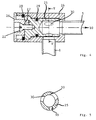
- Fig. 4 shows a second embodiment of the invention Actuating device in which the actuator as Rotating element is executed.
- This rotating element is also located in the gas supply pipe 1 downstream of the (not shown) throttle screw.
- the one corresponding to the one with the Throttle cross section set throttled Gas flow becomes gas nozzles 10 (not shown) through a 90 ° angled pipe part 5 passed.
- the rotating element leaves rotate within a base body 24, the forms an axial extension of the tubular part 5.
- the Rotating element itself consists of a in the base body 24 rotatable throttle body 25, the cylindrical Interior on the one hand in connection with the pipe section 5 stands and on the other hand in openings of different sizes 30 opens at the circumference of the throttle body 25.
- This different sized openings 30 are then depending Throttle position at the mouth of the gas supply pipe 1.
- the circular cylindrical outer wall of the throttle body 25 is in the circular cylindrical inner volume of the base body 24 rotatably supported and by an O-ring 29 opposite Base body 24 sealed.
- One in a groove of the inner wall of the body 24 seated circlip 28 holds the Throttle body 25 in its axial position within the Base body 24.
- a dial 26 is by means of an example as Countersunk screw 22 executed connecting element attached centrally and coaxially to the throttle body 25.
- the dial 26 can be corrugated on its outer circumference or be scored to provide a convenient target for one adjusting hand of an operator or a mechanic Offer.
- the setting wheel 26 also has one eccentric projection 27 projecting in the axial direction on the in a corresponding bore of the Throttle body 25 engages.
- Locking elements, which in corresponding counter elements on the axially opposite surface of the dial 26 latching intervene and the the respective rest positions of the Throttle body 25 are assigned.
- FIG. 5 shows a cross section through the throttle body 25 along the section line V-V in Fig. 4. That of the respective corresponding gas type to be set Throttle cross sections of the circumferential openings 30 in the throttle body 25 are clearly visible.
- This rotary element of the actuating device according to the invention can alternatively be located directly at the gas valve outlet attach, i.e. upstream of that in Fig. 4 not shown throttle screw.
- the device is factory-set to a specific position Throttle screw 2 set to a certain gas type. If the device is to be operated with a different gas type, is only the control element of the invention Actuator on site and by hand in another Bring rest position. The adjustment can thus be made execute the respective gas type on site in a simple manner.
- the actuator in the gas supply pipe 1 to the Gas nozzles 10 can be one type of device for different types of gas be used. To switch to a different gas type all that is required is to manually adjust the control element into the corresponding one Rest position are brought. The gas heater or the actuator itself can be marked provided its rest position of the corresponding gas type assign. There are no measuring devices and none for adjustment special tools are necessary and none are required Gas nozzles to be replaced.
Landscapes
- Engineering & Computer Science (AREA)
- Chemical & Material Sciences (AREA)
- Combustion & Propulsion (AREA)
- Mechanical Engineering (AREA)
- General Engineering & Computer Science (AREA)
- Feeding And Controlling Fuel (AREA)
Abstract
dadurch gekennzeichnet, daß die Stelleinrichtung außerdem im Gaszuführungsrohr (1) ein in mehreren definierten Rastpositionen (I, II, III), die jeweils einer bestimmten Gasart zugeordnet sind, einrastendes Stellelement (3) aufweist.
Description
Claims (10)
- Stelleinrichtung, insbesondere für Gasheizgeräte zur Anpassung an unterschiedliche Gasarten (H, L, F) mit einer in einem Gaszuführungsrohr (1) vorgesehenen, einstellbaren Drosselschraube (2), mit der ein bestimmter Drosselquerschnitt des Gaszuführungsrohrs (1) zur Grundeinstellung auf eine der Gasarten einstellbar ist,
dadurch gekennzeichnet, daß die Stelleinrichtung außerdem im Gaszuführungsrohr (1) ein in mehreren definierten Rastpositionen (I, II, III), die jeweils einer bestimmten Gasart zugeordnet sind, einrastendes Stellelement (3) aufweist. - Stelleinrichtung nach Anspruch 1, dadurch gekennzeichnet, daß das Stellelement (3) stromabwärts von der Drosselschraube (2) liegt.
- Stelleinrichtung nach Anspruch 1 oder 2, dadurch gekennzeichnet, daß das Stellelement (3) wenigstens drei aufeinanderfolgende Rastpositionen (I, II, III) hat, die jeweils der der Gasart entsprechenden Wobbezahl zugeordnet sind, so daß das Stellelement (3) den durchströmten Querschnitt des Gaszuführungsrohrs (1) bei konstanter Grundeinstellung der Drosselschraube (2) zwischen einem maximalen Querschnitt für Erdgas (L) und einem minimalen Querschnitt für Flüssiggas (F) einstellen kann.
- Stelleinrichtung nach einem der vorangehenden Ansprüche, dadurch gekennzeichnet, daß das Stellelement als Stellschieber (3) ausgeführt ist, das koaxial in einer Rohrbuchse (4) des Gaszuführungsrohrs (1) verschiebbar ist, wobei diese Rohrbuchse (4) eine axiale Verlängerung eines um 90° abgewinkelten Rohrteils (5) im Gaszuführungsrohr (1) stromabwärts von der Drosselschraube (2) bildet, und der Stellschieber (3) in Richtung der Achse des um 90° abgewinkelten, zu den Gasdüsen (10) führenden Teils des Gasführungsrohrs rastend verstellbar ist.
- Stelleinrichtung nach einem der vorangehenden Ansprüche, dadurch gekennzeichnet, daß der Stellschieber (3) bolzenförmig ist und eine im Gaszuführungsrohr in Richtung der genannten Achse des um 90° abgewinkelten Teils verschiebliche Schiebenabe (13) und einen damit einstückigen, aus der Rohrbuchse (4) ragenden Schiebekopf (16) aufweist, und die Schiebenabe (13) ein in das abgewinkelte Rohrteil (5) ragendes freies Vorderende (15), einen daran anschließenden, gegenüber der Innenwand (14) der Rohrbuchse (4) abgedichteten, koaxialen Dichtungsabschnitt (17), einen mit mehreren radialen Umfangsnuten, die jeweils den Raststellungen entsprechen, versehenen Rastabschnitt (8) und einen an den Schiebekopf (16) anschließenden Führungsabschnitt (9) aufweist.
- Stelleinrichtung nach Anspruch 5, dadurch gekennzeichnet, daß drei Umfangsnuten (18) am Rastabschnitt (8) der Schiebenabe (13) ausgebildet sind und daß eine federnde Raste (19) an der Innenwand (14) der Rohrbuchse (4) vorgesehen ist, die bei auf den Schiebekopf (16) einwirkendem Druck oder Zug federnd in die jeweilige Umfangsnut (18) einrasten kann.
- Stelleinrichtung nach Anspruch 5 oder 6, dadurch gekennzeichnet, daß der Dichtungsabschnitt (17) durch einen in einer Umfangsnut der Rohrinnenwand (14) der Rohrbuchse (4) liegenden O-Ring (6) abgedichtet ist.
- Stelleinrichtung nach einem der Ansprüche 5 bis 7, dadurch gekennzeichnet, daß sich das freie Vorderende (15) der Schiebenabe (3) stufenförmig verjüngt.
- Stelleinrichtung nach einem der Ansprüche 5 bis 8, dadurch gekennzeichnet, daß das Vorderende (15) der Schiebenabe (3) so gestaltet ist, daß es die lichte Weite des Gaszuführungsrohrs (1) nicht vollständig verschließen kann.
- Stelleinrichtung nach einem der Ansprüche 1 bis 3, dadurch gekennzeichnet, daß das Stellelement als Drehelement ausgeführt ist, welches in einem als zylindrische Rohrbuchse gestalteten Grundkörper (24) eines um 90° abgewinkelten Teils (5) des Gaszuführungsrohrs (1, 5) liegt und welches einen in dem Grundkörper (24) abgedichteten drehbaren Drosselkörper (25) aufweist, durch dessen periphere Wand Drosselöffnungen (30) unterschiedlichen Drosselquerschnitts gehen, die je nach rastender Drehstellung des Drehelements bzw. des Drosselkörpers (25) den durchströmten Innenquerschnitt des Gaszuführungsrohrs (1, 5) an die gewählte Gasart anpassen.
Applications Claiming Priority (2)
| Application Number | Priority Date | Filing Date | Title |
|---|---|---|---|
| DE19752207 | 1997-11-25 | ||
| DE19752207A DE19752207A1 (de) | 1997-11-25 | 1997-11-25 | Stelleinrichtung zur Anpassung an unterschiedliche Gasarten |
Publications (2)
| Publication Number | Publication Date |
|---|---|
| EP0919772A2 true EP0919772A2 (de) | 1999-06-02 |
| EP0919772A3 EP0919772A3 (de) | 1999-09-22 |
Family
ID=7849773
Family Applications (1)
| Application Number | Title | Priority Date | Filing Date |
|---|---|---|---|
| EP98120352A Withdrawn EP0919772A3 (de) | 1997-11-25 | 1998-10-28 | Stelleinrichtung zur Anpassung an unterschiedliche Gasarten |
Country Status (2)
| Country | Link |
|---|---|
| EP (1) | EP0919772A3 (de) |
| DE (1) | DE19752207A1 (de) |
Families Citing this family (1)
| Publication number | Priority date | Publication date | Assignee | Title |
|---|---|---|---|---|
| DE10017990C2 (de) * | 2000-04-11 | 2002-03-07 | Viessmann Werke Kg | Gasgebläsebrenner |
Family Cites Families (8)
| Publication number | Priority date | Publication date | Assignee | Title |
|---|---|---|---|---|
| US3407023A (en) * | 1967-01-05 | 1968-10-22 | Eclipse Fuel Eng Co | Mounting for replaceable gas burner |
| DE2550219A1 (de) * | 1975-11-08 | 1977-05-18 | Seppelfricke Geb Gmbh | Gas-stellglied fuer gasgeraete |
| DE7735735U1 (de) * | 1977-11-18 | 1978-03-02 | Joh. Vaillant Kg, 5630 Remscheid | Einstellbare drosselstelle |
| JPS55142172A (en) * | 1979-04-20 | 1980-11-06 | Matsushita Electric Ind Co Ltd | Gas flow-rate controller |
| DE3039378A1 (de) * | 1980-10-18 | 1982-05-19 | Gebrüder Cramer, 5750 Menden | Einstellaggregat fuer gasbrenner |
| JPS58178116A (ja) * | 1982-04-12 | 1983-10-19 | Matsushita Electric Ind Co Ltd | ガス供給装置 |
| JPS58219321A (ja) * | 1982-06-14 | 1983-12-20 | Matsushita Electric Ind Co Ltd | 燃焼ガス供給装置 |
| DE29518729U1 (de) * | 1995-11-25 | 1996-01-25 | G. Kromschröder AG, 49074 Osnabrück | Brenner mit integrierter Meß- und Stelleinrichtung |
-
1997
- 1997-11-25 DE DE19752207A patent/DE19752207A1/de not_active Ceased
-
1998
- 1998-10-28 EP EP98120352A patent/EP0919772A3/de not_active Withdrawn
Also Published As
| Publication number | Publication date |
|---|---|
| EP0919772A3 (de) | 1999-09-22 |
| DE19752207A1 (de) | 1999-07-29 |
Similar Documents
| Publication | Publication Date | Title |
|---|---|---|
| DE3611909C3 (de) | Vorrichtung zur Steuerung der Menge und/oder des Mischungsverhältnisses eines Brenngas-Luft-Gemisches | |
| DE1960237A1 (de) | Hahn zum Einstellen der Betriebsweise an einem Gasheizgeraet | |
| DE3120637C2 (de) | ||
| EP0919772A2 (de) | Stelleinrichtung zur Anpassung an unterschiedliche Gasarten | |
| EP0508164B1 (de) | Vorrichtung zur Regelung der Menge und/oder des Mischungsverhältnisses eines Brenngas-Luft-Gemisches | |
| DE69602993T2 (de) | Vorrichtung zum Zusammenbetätigen von zwei eine rotierende steuerungsenthaltenden Elementen, und Schweissbrenner mit einer solchen Vorrichtung ausgerüstet | |
| DE680057C (de) | Gasbrenner | |
| DE2847380C2 (de) | Druckmittelbetriebener Regler mit Rückführung, insbesondere Stellungsregler | |
| DE2759084C2 (de) | Brenner für Gas und/oder Öl als Brennstoff | |
| DE2941543C2 (de) | Vorrichtung zur Steuerung der Gaszufuhr | |
| DE2844983A1 (de) | Vorrichtung zum mischen von zwei fluiden und mit ihr ausgestatteter schieber | |
| DE2432675C3 (de) | Regelventil | |
| DE202018006471U1 (de) | Ventilzufuhrvorrichtung | |
| DE2903747A1 (de) | Gasregler, insbesondere fuer gasbrenner mit duesen | |
| DE2536073A1 (de) | Brennerkopf, insbesondere fuer gasfoermige brennstoffe | |
| DE1907735A1 (de) | An einer Luft- oder Sauerstoffzuleitung angeschlossener Brenner | |
| DE934118C (de) | Gas-Luft-Mischvorrichtung fuer Gasfeuerungsanlagen | |
| DE4420296C2 (de) | Gas-Luft-Verhältnisregler und dessen Verwendung in einer Gasbrennereinheit | |
| DE531512C (de) | Absperrvorrichtung fuer Schweissbrenner | |
| DE302328C (de) | ||
| DE2810449A1 (de) | Gashahn | |
| DE656847C (de) | OElbrenner mit gleichbleibender Luftzufuhr zum Brennermischraum | |
| DE4303700C2 (de) | Vorrichtung zur Regelung des Gas-Luft-Verhältnisses bei einem Gasvormischbrenner | |
| DE849161C (de) | Zerstaeuberbrenner | |
| AT395060B (de) | Geraet mit einem brenner |
Legal Events
| Date | Code | Title | Description |
|---|---|---|---|
| PUAI | Public reference made under article 153(3) epc to a published international application that has entered the european phase |
Free format text: ORIGINAL CODE: 0009012 |
|
| AK | Designated contracting states |
Kind code of ref document: A2 Designated state(s): AT BE CH CY DE DK ES FI FR GB GR IE IT LI LU MC NL PT SE |
|
| AX | Request for extension of the european patent |
Free format text: AL;LT;LV;MK;RO;SI |
|
| PUAL | Search report despatched |
Free format text: ORIGINAL CODE: 0009013 |
|
| AK | Designated contracting states |
Kind code of ref document: A3 Designated state(s): AT BE CH CY DE DK ES FI FR GB GR IE IT LI LU MC NL PT SE |
|
| AX | Request for extension of the european patent |
Free format text: AL;LT;LV;MK;RO;SI |
|
| RIC1 | Information provided on ipc code assigned before grant |
Free format text: 6F 23N 1/00 A |
|
| AKX | Designation fees paid | ||
| REG | Reference to a national code |
Ref country code: DE Ref legal event code: 8566 |
|
| STAA | Information on the status of an ep patent application or granted ep patent |
Free format text: STATUS: THE APPLICATION IS DEEMED TO BE WITHDRAWN |
|
| 18D | Application deemed to be withdrawn |
Effective date: 20000323 |