EP0919772A2 - Actuating device for adjusting to different types of gas - Google Patents
Actuating device for adjusting to different types of gas Download PDFInfo
- Publication number
- EP0919772A2 EP0919772A2 EP98120352A EP98120352A EP0919772A2 EP 0919772 A2 EP0919772 A2 EP 0919772A2 EP 98120352 A EP98120352 A EP 98120352A EP 98120352 A EP98120352 A EP 98120352A EP 0919772 A2 EP0919772 A2 EP 0919772A2
- Authority
- EP
- European Patent Office
- Prior art keywords
- gas
- section
- supply pipe
- gas supply
- throttle
- Prior art date
- Legal status (The legal status is an assumption and is not a legal conclusion. Google has not performed a legal analysis and makes no representation as to the accuracy of the status listed.)
- Withdrawn
Links
Images

Classifications
-
- F—MECHANICAL ENGINEERING; LIGHTING; HEATING; WEAPONS; BLASTING
- F23—COMBUSTION APPARATUS; COMBUSTION PROCESSES
- F23N—REGULATING OR CONTROLLING COMBUSTION
- F23N1/00—Regulating fuel supply
- F23N1/007—Regulating fuel supply using mechanical means
-
- F—MECHANICAL ENGINEERING; LIGHTING; HEATING; WEAPONS; BLASTING
- F23—COMBUSTION APPARATUS; COMBUSTION PROCESSES
- F23N—REGULATING OR CONTROLLING COMBUSTION
- F23N5/00—Systems for controlling combustion
- F23N5/26—Details
-
- F—MECHANICAL ENGINEERING; LIGHTING; HEATING; WEAPONS; BLASTING
- F23—COMBUSTION APPARATUS; COMBUSTION PROCESSES
- F23N—REGULATING OR CONTROLLING COMBUSTION
- F23N2227/00—Ignition or checking
- F23N2227/20—Calibrating devices
Definitions
- the invention relates to an actuating device, in particular for gas heaters to adapt to different Types of gas with a gas supply pipe provided in a adjustable throttle screw with which a specific Throttle cross section of the gas supply pipe for basic setting can be set to one of the gas types.
- the calorific and calorific value depends on the Condition of the gas supplied, e.g. of natural gas, LPG, etc.
- a measure of the thermal output of a Gas burner is the Wobbe number. If the gas quality changes, i.e. the calorific value, the density and the pressure, so changes the heat output in relation to the Wobbe number.
- This task is done with a generic Actuator solved according to the invention in that the Actuating device other than that in the gas supply pipe Throttle screw with which a certain basic throttle cross section of the gas supply pipe for one of the gas types is adjustable, one in several in the gas supply pipe defined rest positions, each of a certain Are assigned to the type of gas, has a locking actuator.
- This control element is preferably located downstream of the Throttle screw.
- control element at least three consecutive rest positions on, each of the Wobbe number corresponding to the gas type assigned.
- flow through Cross section of the gas supply pipe with constant basic setting the throttle screw with the actuator on one maximum cross section for a specific type of natural gas and set a minimum cross-section for LPG become.
- the adjustment can be adjusted to do the gas type easily on site, where no measuring devices and no special tools necessary and no gas nozzles need to be replaced.
- the actuator is as a Adjusting slide executed coaxially in a pipe socket of the gas supply pipe is displaceable, and this pipe socket forms an axial extension of 90 ° angled pipe part in the gas supply pipe downstream from the throttle screw, with the adjusting slide in the Pipe bushing in the direction of the axis by 90 ° angled part leading to the gas nozzles Gas supply pipe is adjustable latching.
- the interior slide is preferred bolt-shaped and has one in the direction of said axis of the part of the gas supply pipe which is angled by 90 ° sliding hub and one preferred one-piece sliding head protruding from the gas supply pipe on.
- the sliding hub is in one piece and in one, in the angled tube part projecting free front end, one then, opposite the inner wall of the pipe bushing sealed coaxial sealing section, one with several radial circumferential grooves, each of which Allow locking positions, provided locking section and a guide section adjoining the sliding head assigned.
- the Sealing of the sealing section against the inner pipe wall is preferably carried out by a in a circumferential groove Inner tube wall of the O-ring.
- the free The front end of the sliding hub is tapered or stepped conical that it is the inside diameter of the gas supply pipe cannot completely close.
- control element is as executed a rotating element, which is also in a Pipe bushing of the gas guide pipe sits and in three different locking positions can be rotated so that Depending on the resting position, a different amount of gas can flow through the gas supply pipe.
- the rotary element in an axial extension a pipe part angled by 90 ° in the gas supply pipe insert downstream of the throttle screw.
- the rotating element is located directly at the gas valve outlet, i.e. upstream of the throttle screw sits.
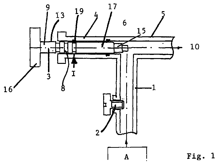
- Fig. 1 shows the slide valve 3 of the invention Actuator in one of the gas type L (natural gas) first rest position I, at which the flow Internal cross section of the gas supply pipe 1 is maximum.
- L natural gas
- Fig. 2 shows the same actuating device, the Adjusting slide is in a second detent position II, for a second type of gas (H-gas) a medium one flowed through internal cross section of the gas supply pipe 1 sets.
- H-gas second type of gas
- Fig. 3 shows the slide valve 3 in one third rest position III, that of a liquefied gas type is assigned and in which the flowed through internal cross-section of the gas supply pipe 1 is minimal.
- Throttle cross-section through the throttle screw 2 is set, has remained unchanged.
- This Throttle cross section corresponds to a basic setting for a certain type of gas, e.g. for the L-gas.
- the slide valve 3 described in more detail below is located located in the gas supply pipe 1 at a downstream of the Throttle screw 2 position. Gas flows from one Gas fitting A through the gas supply pipe 1 at the through the Throttle screw 2 formed throttle point over in one 90 ° angled pipe section 5, which the gas to (not shown) gas nozzles 10 conducts.
- the slide 3 leaves itself within an extension designed as a tubular bushing of the pipe part 5 angled by 90 ° and coaxial adjust with a click.
- the adjusting slide 3 is a total bolt-shaped and consists of one in the named Pipe socket 4 in the direction of the axis of the angled by 90 ° Part 5 slidable sliding hub 13 and a so one-piece sliding head 16 protruding from the tubular sleeve to actuate the setting slide 3.
- This sliding hub 13 in turn has a inside of the gas supply pipe 1, i.e. into the inside of the angled pipe part 5 protruding free front end 15, an adjoining, sealed against the inner wall 14 of the tubular bushing 4, coaxial sealing section 17, one with several radial circumferential grooves 18, each of the locking positions I-III are assigned, provided locking section 8 and one attached to it and to the sliding head 16 Guide section 9.
- a Resilient catch 19 is provided, which at one on the Sliding head 16 acting pressure or train resilient in a the circumferential grooves 18 can snap into place.
- the spring force of the spring catch is 19 so strong on the one hand that an unintentional adjustment the slide valve is excluded, however on the other hand, soft enough that the slide 3 on the head 16 can be adjusted by hand without special tools.
- the slide valve represents a middle one flowed through internal cross section of the gas supply pipe 1 which corresponds to the Wobbe number for the H natural gas.
- the front end 15 is the Sliding hub 13 tapers stepwise so that it flows through Cross section of the gas supply pipe 1 is not can completely close.
- the gas supply pipe 1 in the above Embodiment of the actuating device according to the invention Is angled 90 ° and the adjusting slide 3 on the angled Intervenes and in the extension of the the pipe nozzle 5 leading tube part 5 forming tube bushing 4 is displaceable, the invention is not based on the shown constructive embodiment limited.
- Angles e.g. 180 ° angle, the gas supply pipe 1 when in use enables the actuating device according to the invention can or can be.
- This slide valve 3 can be a simple turned part and thus inexpensive produce.
- the guide section 9 can guide means (not shown) that only the linear movement of the Allow slider 3.
- Fig. 4 shows a second embodiment of the invention Actuating device in which the actuator as Rotating element is executed.
- This rotating element is also located in the gas supply pipe 1 downstream of the (not shown) throttle screw.
- the one corresponding to the one with the Throttle cross section set throttled Gas flow becomes gas nozzles 10 (not shown) through a 90 ° angled pipe part 5 passed.
- the rotating element leaves rotate within a base body 24, the forms an axial extension of the tubular part 5.
- the Rotating element itself consists of a in the base body 24 rotatable throttle body 25, the cylindrical Interior on the one hand in connection with the pipe section 5 stands and on the other hand in openings of different sizes 30 opens at the circumference of the throttle body 25.
- This different sized openings 30 are then depending Throttle position at the mouth of the gas supply pipe 1.
- the circular cylindrical outer wall of the throttle body 25 is in the circular cylindrical inner volume of the base body 24 rotatably supported and by an O-ring 29 opposite Base body 24 sealed.
- One in a groove of the inner wall of the body 24 seated circlip 28 holds the Throttle body 25 in its axial position within the Base body 24.
- a dial 26 is by means of an example as Countersunk screw 22 executed connecting element attached centrally and coaxially to the throttle body 25.
- the dial 26 can be corrugated on its outer circumference or be scored to provide a convenient target for one adjusting hand of an operator or a mechanic Offer.
- the setting wheel 26 also has one eccentric projection 27 projecting in the axial direction on the in a corresponding bore of the Throttle body 25 engages.
- Locking elements, which in corresponding counter elements on the axially opposite surface of the dial 26 latching intervene and the the respective rest positions of the Throttle body 25 are assigned.
- FIG. 5 shows a cross section through the throttle body 25 along the section line V-V in Fig. 4. That of the respective corresponding gas type to be set Throttle cross sections of the circumferential openings 30 in the throttle body 25 are clearly visible.
- This rotary element of the actuating device according to the invention can alternatively be located directly at the gas valve outlet attach, i.e. upstream of that in Fig. 4 not shown throttle screw.
- the device is factory-set to a specific position Throttle screw 2 set to a certain gas type. If the device is to be operated with a different gas type, is only the control element of the invention Actuator on site and by hand in another Bring rest position. The adjustment can thus be made execute the respective gas type on site in a simple manner.
- the actuator in the gas supply pipe 1 to the Gas nozzles 10 can be one type of device for different types of gas be used. To switch to a different gas type all that is required is to manually adjust the control element into the corresponding one Rest position are brought. The gas heater or the actuator itself can be marked provided its rest position of the corresponding gas type assign. There are no measuring devices and none for adjustment special tools are necessary and none are required Gas nozzles to be replaced.
Landscapes
- Engineering & Computer Science (AREA)
- Chemical & Material Sciences (AREA)
- Combustion & Propulsion (AREA)
- Mechanical Engineering (AREA)
- General Engineering & Computer Science (AREA)
- Feeding And Controlling Fuel (AREA)
Abstract
Die Erfindung betrifft eine Stelleinrichtung, insbesondere
für Gasheizgeräte zur Anpassung an unterschiedliche
Gasarten (H, L, F) mit einer in einem Gaszuführungsrohr (1)
vorgesehenen, einstellbaren Drosselschraube (2), mit der
ein bestimmter Drosselquerschnitt des Gaszuführungsrohrs
(1) zur Grundeinstellung auf eine der Gasarten einstellbar
ist,
dadurch gekennzeichnet, daß die Stelleinrichtung außerdem
im Gaszuführungsrohr (1) ein in mehreren definierten
Rastpositionen (I, II, III), die jeweils einer bestimmten
Gasart zugeordnet sind, einrastendes Stellelement (3)
aufweist.
characterized in that the actuating device also has an actuating element (3) which engages in a plurality of defined latching positions (I, II, III), each associated with a specific type of gas, in the gas supply pipe (1).
Description
Die Erfindung betrifft eine Stelleinrichtung, insbesondere für Gasheizgeräte zur Anpassung an unterschiedliche Gasarten mit einer in einem Gaszuführungsrohr vorgesehenen, einstellbaren Drosselschraube, mit der ein bestimmter Drosselquerschnitt des Gaszuführungsrohrs zur Grundeinstellung auf eine der Gasarten einstellbar ist.The invention relates to an actuating device, in particular for gas heaters to adapt to different Types of gas with a gas supply pipe provided in a adjustable throttle screw with which a specific Throttle cross section of the gas supply pipe for basic setting can be set to one of the gas types.
Beim betrieb von Wärmeübertragungs-, z.B. Gasheizungsgeräten, hängt der Brenn- und Heizwert von der Beschaffenheit des zugeführten Gases, z.B. von Erdgas, Flüssiggas usw. ab. Ein Maß für die Wärmeleistung eines Gasbrenners ist die Wobbezahl. Ändert sich die Gasqualität, d.h. der Brennwert, die Dichte und der Druck, so ändert sich die Wärmeleistung im Verhältnis der Wobbezahl.When operating heat transfer, e.g. Gas heating devices, the calorific and calorific value depends on the Condition of the gas supplied, e.g. of natural gas, LPG, etc. A measure of the thermal output of a Gas burner is the Wobbe number. If the gas quality changes, i.e. the calorific value, the density and the pressure, so changes the heat output in relation to the Wobbe number.
Aus diesem Grunde ist eine Anpassung von gasbetriebenen Wärmeübertragungsgeräten, insbesondere von Gasheizgeräten, an Gasarten mit unterschiedlicher Wobbezahl gefordert.For this reason, an adaptation of gas powered Heat transfer devices, especially gas heaters, required for gas types with different wobbe numbers.
Um die obige Forderung zu erfüllen, werden bei Gasheizgeräten üblicherweise die Gasdüsen entsprechend der einzelnen Gasarten, mit denen die Gasheizgeräte betrieben werden, unterschiedlich abgestimmt. Bei einer Baureihe von Junkers Vormischbrennergeräten mit pneumatischer Gas-/Luftverbundregelung wird nicht mit unterschiedlichen Gasdüsen gearbeitet, sondern die Anpassung an die Gasarten erfolgt über die Einstellung einer Drosselschraube im Gaszuführungsrohr zum Brenner. Für die einzelnen Gasarten gibt es unterschiedliche Gerätetypen, die sich durch die herstellerseits vorgenommene Einstellung dieser Drosselschraube unterscheiden.To meet the above requirement, at Gas heaters usually match the gas nozzles individual types of gas with which the gas heaters are operated are coordinated differently. With a series of Junkers premix burner devices with pneumatic gas / air compound control will not use different gas nozzles worked, but the adaptation to the gas types takes place about setting a throttle screw in the gas supply pipe to the burner. For the individual gas types there there are different types of devices, which are characterized by the manufacturer-made adjustment of this throttle screw differentiate.
Es ist Aufgabe der Erfindung, eine Stelleinrichtung zur Anpassung, insbesondere von Gasheizgeräten an unterschiedliche Gasarten so zu ermöglichen, daß ein einziger Gerätetyp für verschiedene Gasarten eingesetzt werden kann und daß die Umstellung auf eine andere Gasart auf einfache Weise ohne Meßgeräte und Werkzeuge am Ort des Gasheizgeräts erfolgen kann.It is an object of the invention to provide an actuator for Adaptation, especially of gas heaters to different ones To allow gas types so that a single Device type can be used for different types of gas and that the switch to a different type of gas is easy Way without measuring instruments and tools at the location of the gas heater can be done.
Diese Aufgabe wird bei einer gattungsgemäßen Stelleinrichtung erfindungsgemäß dadurch gelöst, daß die Stelleinrichtung außer der im Gaszuführungsrohr liegenden Drosselschraube, mit der ein bestimmter Grund-Drosselquerschnitt des Gaszuführungsrohrs für eine der Gasarten einstellbar ist, im Gaszuführungsrohr ein in mehreren definierten Rastpositionen, die jeweils einer bestimmten Gasart zugeordnet sind, einrastendes Stellelement aufweist.This task is done with a generic Actuator solved according to the invention in that the Actuating device other than that in the gas supply pipe Throttle screw with which a certain basic throttle cross section of the gas supply pipe for one of the gas types is adjustable, one in several in the gas supply pipe defined rest positions, each of a certain Are assigned to the type of gas, has a locking actuator.
Vorzugsweise liegt dieses Stellelement stromabwärts von der Drosselschraube.This control element is preferably located downstream of the Throttle screw.
Gemäß einer vorteilhaften Ausführungsform weist das Stellelement wenigstens drei aufeinanderfolgende Rastpositionen auf, die jeweils der der Gasart entsprechenden Wobbezahl zugeordnet sind. Auf diese Weise kann der durchströmte Querschnitt des Gaszuführungsrohrs bei konstanter Grundeinstellung der Drosselschraube mit dem Stellelement auf einen maximalen Querschnitt für eine bestimmte Erdgassorte und einen minimalen Querschnitt für Flüssiggas eingestellt werden.According to an advantageous embodiment, the control element at least three consecutive rest positions on, each of the Wobbe number corresponding to the gas type assigned. In this way, the flow through Cross section of the gas supply pipe with constant basic setting the throttle screw with the actuator on one maximum cross section for a specific type of natural gas and set a minimum cross-section for LPG become.
Durch die nachstehend beschriebene bevorzugte Ausführungsform der Stelleinrichtung läßt sich die Anpassung an die Gasart auf einfache Weise vor Ort erledigen, wobei keine Meßgeräte und keine besonderen Werkzeuge notwendig sind und keine Gasdüsen ausgewechselt werden müssen.By the preferred embodiment described below the adjustment can be adjusted to do the gas type easily on site, where no measuring devices and no special tools necessary and no gas nozzles need to be replaced.
Bei einer Ausführungsform ist das Stellelement als ein Stellschieber ausgeführt, der koaxial in einer Rohrbuchse des Gaszuführungsrohrs verschiebbar ist, und diese Rohrbuchse bildet eine axiale Verlängerung eines um 90° abgewinkelten Rohrteils im Gaszuführungsrohr stromabwärts von der Drosselschraube, wobei der Stellschieber in der Rohrbuchse in Richtung der Achse dieses um 90° abgewinkelten, zu den Gasdüsen führenden Teils des Gaszuführungsrohrs rastend verstellbar ist.In one embodiment, the actuator is as a Adjusting slide executed coaxially in a pipe socket of the gas supply pipe is displaceable, and this pipe socket forms an axial extension of 90 ° angled pipe part in the gas supply pipe downstream from the throttle screw, with the adjusting slide in the Pipe bushing in the direction of the axis by 90 ° angled part leading to the gas nozzles Gas supply pipe is adjustable latching.
Bei einem Gaszuführungsrohr mit üblicherweise kreiszylindrischer Innenwand ist der Stellschieber bevorzugt bolzenförmig und weist eine in Richtung der genannten Achse des um 90° abgewinkelten Teils des Gaszuführungsrohrs verschiebliche Schiebenabe und einen damit bevorzugt einstückigen, aus dem Gaszuführungsrohr ragenden Schiebekopf auf. Die Schiebenabe ist einstückig und in ein, in das abgewinkelte Rohrteil ragendes freies Vorderende, einen daran anschließenden, gegenüber der Innenwand der Rohrbuchse abgedichteten koaxialen Dichtungsabschnitt, einen mit mehreren radialen Umfangsnuten, die jeweils die Raststellungen ermöglichen, versehenen Rastabschnitt und einen an den Schiebekopf anschließenden Führungsabschnitt eingeteilt.In the case of a gas supply pipe with a usually circular cylindrical one The interior slide is preferred bolt-shaped and has one in the direction of said axis of the part of the gas supply pipe which is angled by 90 ° sliding hub and one preferred one-piece sliding head protruding from the gas supply pipe on. The sliding hub is in one piece and in one, in the angled tube part projecting free front end, one then, opposite the inner wall of the pipe bushing sealed coaxial sealing section, one with several radial circumferential grooves, each of which Allow locking positions, provided locking section and a guide section adjoining the sliding head assigned.
Bevorzugt sind drei Umfangsnuten am Rastabschnitt der Schiebenabe ausgebildet, und an der Innenwand der Rohrbuchse ist eine federnde Raste angebracht, die bei auf den Schiebekopf einwirkendem Druck oder Zug federnd in die jeweilige Umfangsnut des Rastabschnitts einrasten kann. Die Abdichtung des Dichtungsabschnitts gegenüber der Rohrinnenwand erfolgt bevorzugt durch einen in einer Umfangsnut der Rohrinnenwand der Rohrbuchse liegenden O-Ring. Das freie Vorderende der Schiebenabe ist stufenförmig verjüngt oder konisch, daß es die lichte Weite des Gaszuführungsrohrs nicht vollständig verschließen kann.Three circumferential grooves are preferred on the latching section Sliding hub formed, and on the inner wall of the Pipe bushing has a resilient catch attached to it the pushing head acting pressure or tension in the spring can snap the respective circumferential groove of the latching section. The Sealing of the sealing section against the inner pipe wall is preferably carried out by a in a circumferential groove Inner tube wall of the O-ring. The free The front end of the sliding hub is tapered or stepped conical that it is the inside diameter of the gas supply pipe cannot completely close.
Bei einer weiteren Ausführungsform ist das Stellelement als ein Drehelement ausgeführt, das ebenfalls in einer Rohrbuchse des Gasführungsrohrs sitzt und darin in drei verschiedenen Rastpositionen rastend verdrehbar ist, so daß je nach Raststellung eine unterschiedlich große Gasmenge durch das Gaszuführungsrohr strömen kann. Auch hier ist bevorzugt, das Drehelement in eine axiale Verlängerung eines um 90° abgewinkelten Rohrteils im Gaszuführungsrohr stromabwärts von der Drosselschraube einzufügen. Alternativ ist es auch möglich, daß das Drehelement direkt am Gasarmaturausgang, d.h. stromaufwärts von der Drosselschraube sitzt.In a further embodiment, the control element is as executed a rotating element, which is also in a Pipe bushing of the gas guide pipe sits and in three different locking positions can be rotated so that Depending on the resting position, a different amount of gas can flow through the gas supply pipe. Here too preferred, the rotary element in an axial extension a pipe part angled by 90 ° in the gas supply pipe insert downstream of the throttle screw. Alternatively it is also possible that the rotating element is located directly at the gas valve outlet, i.e. upstream of the throttle screw sits.
Nachfolgend werden weitere Merkmale und Vorteile der Erfindung anhand der nachstehenden, zwei verschiedene Ausführungsformen beschreibenden Beschreibung deutlich, wenn diese in Bezug auf die beiliegenden Zeichnungsfiguren gelesen wird.Below are other features and advantages of Invention based on the following, two different Descriptive description descriptive embodiments, if this in relation to the accompanying drawing figures is read.
Fig. 1 Zeigt den Stellschieber 3 der erfindungsgemäßen
Stelleinrichtung in einer der Gasart L (Erdgas) entsprechenden
ersten Rastposition I, bei der der durchströmte
Innenquerschnitt des Gaszuführungsrohrs 1 maximal ist.Fig. 1 shows the
Fig. 2 zeigt dieselbe Stelleinrichtung, wobei sich der
Stellschieber in einer zweiten Rastposition II befindet,
die für eine Zweite Gasart (H-Gas) einen mittleren
durchströmten Innenquerschnitt des Gaszuführungsrohrs 1
einstellt.Fig. 2 shows the same actuating device, the
Adjusting slide is in a second detent position II,
for a second type of gas (H-gas) a medium one
flowed through internal cross section of the
Schließlich zeigt Fig. 3 den Stellschieber 3 in einer
dritten Rastposition III, die einer Flüssiggasart
zugeordnet ist und bei der der durchströmte Innenquerschnitt
des Gaszuführungsrohrs 1 minimal ist.Finally, Fig. 3 shows the
Insgesamt zeigen die Figuren 1 bis 3 deutlich, daß der
Drosselquerschnitt, der durch die Drosselschraube 2
eingestellt wird, unverändert geblieben ist. Dieser
Drosselquerschnitt entspricht einer Grundeinstellung für
eine bestimmte Gasart, z.B. für das L-Gas.Overall, Figures 1 to 3 clearly show that the
Throttle cross-section, through the
Der nachstehend näher beschriebene Stellschieber 3 befindet
sich im Gaszuführungsrohr 1 an einer stromabwärts von der
Drosselschraube 2 gelegenen Position. Gas strömt von einer
Gasarmatur A durch das Gaszuführungsrohr 1 an der durch die
Drosselschraube 2 gebildeten Drosselstelle vorbei in einen
um 90° abgewinkelten Rohrabschnitt 5, der das Gas zu (nicht
gezeigten) Gasdüsen 10 leitet. Der Stellschieber 3 läßt
sich innerhalb einer als Rohrbuchse gestalteten Verlängerung
des um 90° abgewinkelten Rohrteils 5 koaxial und
rastend verstellen. Der Stellschieber 3 ist insgesamt
bolzenförmig und besteht aus einer in der genannten
Rohrbuchse 4 in Richtung der Achse des um 90° abgewinkelten
Teils 5 verschieblichen Schiebenabe 13 und einem damit
einstückigen, aus der Rohrbuchse ragenden Schiebekopf 16
zur Betätigung des Stellschiebers 3. Diese Schiebenabe 13
weist ihrerseits ein in das Innere des Gaszuführungsrohrs
1, d.h. in das Innere des abgewinkelten Rohrteils 5
ragendes freies Vorderende 15, einen daran anschließenden,
gegenüber der Innenwand 14 der Rohrbuchse 4 abgedichteten,
koaxialen Dichtungsabschnitt 17, einen mit mehreren
radialen Umfangsnuten 18, die jeweils den Raststellungen I-III
zugeordnet sind, versehenen Rastabschnitt 8 und einen
daran und an den Schiebekopf 16 anschließenden
Führungsabschnitt 9 auf.The
Zur rastenden Verstellung des Stellschiebers 3 weist dessen
Rastabschnitt 8 an der Schiebenabe drei Umfangsnuten 18
auf, und an der Innenwand 14 der Rohrbuchse 4 ist eine
federnde Raste 19 vorgesehen, die bei einem auf den
Schiebekopf 16 einwirkenden Druck oder Zug federnd in eine
der Umfangsnuten 18 einrasten kann.For the locking adjustment of the
Selbstverständlich ist die Federkraft der federnden Raste
19 einerseits so stark, daß eine unbeabsichtigte Verstellung
des Stellschiebers ausgeschlossen ist, jedoch
andererseits weich genug, daß der Stellschieber 3 am Kopf
16 von Hand ohne besonderes Werkzeug verstellt werden kann.Of course, the spring force of the spring catch is
19 so strong on the one hand that an unintentional adjustment
the slide valve is excluded, however
on the other hand, soft enough that the
Bei der in Fig. 2 gezeigten mittleren Raststellung II, die
einem Erdgas (H-Gas) entspricht, befindet sich der
Stellschieber 3 in einer mittleren Rastposition, die durch
Druck auf den Schiebekopf 16 von Fig. 1 erreicht wird. In
dieser Position II stellt der Stellschieber einen mittleren
durchströmten Innenquerschnitt des Gaszuführungsrohrs 1
ein, was der Wobbezahl für das H-Erdgas entspricht.In the middle locking position II shown in Fig. 2, the
corresponds to a natural gas (H-gas), is located
Adjusting
In der in Fig. 3 gezeigten dritten Position III schließlich
ist der Stellschieber 3 noch mehr in die Rohrbuchse 4
eingedrückt worden, so daß der durchströmte Querschnitt des
Gaszuführungsrohrs 1 noch weiter verengt ist. Diese
Position III ist Flüssiggas zugeordnet.Finally in the third position III shown in FIG. 3
the
Wie die Figuren 1 bis 3 zeigen, ist das vordere Ende 15 der
Schiebenabe 13 stufenförmig verjüngt, so daß es den durchströmten
Querschnitt des Gaszuführungsrohrs 1 nicht
vollständig verschließen kann.As shown in Figures 1 to 3, the
Obwohl das Gaszuführungsrohr 1 bei der oben beschriebenen
Ausführungsform der erfindungsgemäßen Stelleinrichtung um
90° abgewinkelt ist und der Stellschieber 3 an der abgewinkelten
Stelle eingreift und in der eine Verlängerung des zu
den Gasdüsen 10 führenden Rohrteils 5 bildenden Rohrbuchse
4 verschiebbar ist, ist die Erfindung nicht auf die
dargestellte konstruktive Ausführungsform beschränkt. Dem
Fachmann ist es unmittelbar einleuchtend, daß andere
Winkel, z.B. 180°-Winkel, des Gaszuführungsrohrs 1 bei Verwendung
der erfindungsgemäßen Stelleinrichtung ermöglicht
werden kann oder können.Although the
Selbstverständlich läßt sich der bei der Erfingung
verwendete Stellschieber 3 auch in einem nicht abgewinkelten
Gaszuführungsrohr 1 verwenden. Dieser Stellschieber
3 läßt sich als einfaches Drehteil und somit kostengünstig
herstellen. Der Führungsabschnitt 9 kann Führungsmittel
(nicht gezeigt) aufweisen, die nur die lineare Bewegung des
Stellschiebers 3 gestatten.Of course, this can be done with the invention
used
Fig. 4 zeigt eine Zweite Ausführungsform der erfindungsgemäßen
Stelleinrichtung, bei der das Stellelement als
Drehelement ausgeführt ist. Dieses Drehelement liegt ebenfalls
im Gaszuführungsrohr 1 stromabwärts von der (nicht
gezeigten) Drosselschraube. Der entsprechend dem mit dem
Drehelement eingestellten Drosselquerschnitt gedrosselte
Gasstrom wird zu (nicht gezeigten) Gasdüsen 10 durch ein um
90° abgewinkeltes Rohrteil 5 geleitet. Das Drehelement läßt
sich innerhalb eines Grundkörpers 24 rastend verdrehen, der
eine axiale Verlängerung des Rohrteils 5 bildet. Das
Drehelement selbst besteht aus einem im Grundkörper 24
drehbaren Drosselkörper 25, dessen zylinderförmiger
Innenraum einerseits mit dem Rohrabschnitt 5 in Verbindung
steht und andererseits in unterschiedlich großen Öffnungen
30 am Umfang des Drosselkörpers 25 mündet. Diese
unterschiedlich großen Öffnungen 30 liegen dann je nach
Drosselstellung an der Mündung des Gaszuführungsrohrs 1 an.
Die kreiszylindrische Außenwand des Drosselkörpers 25 ist
im kreiszylindrischen Innenvolumen des Grundkörpers 24
drehbar gelagert und durch einen O-Ring 29 gegenüber dem
Grundkörper 24 abgedichtet. Ein in einer Nut der Innenwand
des Grundkörpers 24 sitzender Sicherungsring 28 hält den
Drosselkörper 25 in seiner axialen Position innerhalb des
Grundkörpers 24.Fig. 4 shows a second embodiment of the invention
Actuating device in which the actuator as
Rotating element is executed. This rotating element is also located
in the
Ein Einstellrad 26 ist mittels eines beispielhaft als
Senkkopfschraube 22 ausgeführten Verbindungselements
zentrisch und koaxial an dem Drosselkörper 25 befestigt.
Das Einstellrad 26 kann an seinem Außenumfang geriffelt
oder gekerbt sein, um eine günstige Angriffsfläche für eine
einstellende Hand einer Bedienperson oder eines Monteurs zu
bieten. Das Einstellrad 26 weist ferner einen
exzentrischen, in axialer Richtung ragenden Vorsprung 27
auf, der in eine korrespondierende Bohrung des
Drosselkörpers 25 eingreift. An der Stirnfläche des
Grundkörpers 24 befinden sich in Fig. 4 nicht gezeigte
Rastelemente, die in entsprechende Gegenelemente an der
axial gegenüberliegenden Fläche des Einstellrads 26 rastend
eingreifen und die den jeweiligen Raststellungen des
Drosselkörpers 25 zugeordnet sind.A
Fig. 5 zeigt einen Querschnitt durch den Drosselkörper 25
längs der Schnittlinie V-V in Fig. 4. Die der jeweiligen
einzustellenden Gasart entsprechenden unterschiedlichen
Drosselquerschnitte der Umfangsöffnungen 30 im Drosselkörper
25 sind deutlich zu erkennen.5 shows a cross section through the
Auch dieses Drehelement der erfindungsgemäßen Stelleinrichtung läßt sich alternativ direkt am Gasarmaturausgang anbringen, d.h. stromaufwärts von der in Fig. 4 nicht dargestellten Drosselschraube.This rotary element of the actuating device according to the invention can alternatively be located directly at the gas valve outlet attach, i.e. upstream of that in Fig. 4 not shown throttle screw.
Das Gerät wird werkseitig mit einer bestimmten Position der
Drosselschraube 2 auf eine bestimmte Gasart eingestellt.
Soll das Gerät mit einer anderen Gasart betrieben werden,
ist lediglich das Stellelement der erfindungsgemäßen
Stelleinrichtung vor Ort und von Hand in eine andere
Rastposition zu bringen. Somit läßt sich die Anpassung an
die jeweilige Gasart auf einfache Weise vor Ort ausführen.The device is factory-set to a specific
Durch die Stelleinrichtung im Gaszuführungsrohr 1 zu den
Gasdüsen 10 kann ein Gerätetyp für verschiedene Gasarten
eingesetzt werden. Zur Umstellung auf eine andere Gasart
muß lediglich das Stellelement von Hand in die entsprechende
Rastposition gebracht werden. Das Gasheizgerät
oder das Stellelement selbst läßt sich mit Markierungen
versehen, die seine Rastposition der entsprechenden Gasart
zuordnen. Zur Verstellung sind keine Meßgeräte und keine
speziellen Werkzeuge notwendig und es müssen auch keine
Gasdüsen ausgewechselt werden.By the actuator in the
Claims (10)
dadurch gekennzeichnet, daß die Stelleinrichtung außerdem im Gaszuführungsrohr (1) ein in mehreren definierten Rastpositionen (I, II, III), die jeweils einer bestimmten Gasart zugeordnet sind, einrastendes Stellelement (3) aufweist.Actuating device, in particular for gas heaters for adapting to different types of gas (H, L, F) with an adjustable throttle screw (2) provided in a gas supply pipe (1), with which a specific throttle cross section of the gas supply pipe (1) can be set to one of the gas types for basic setting is
characterized in that the actuating device also has an actuating element (3) which engages in a plurality of defined latching positions (I, II, III), each associated with a specific type of gas, in the gas supply pipe (1).
Applications Claiming Priority (2)
| Application Number | Priority Date | Filing Date | Title |
|---|---|---|---|
| DE19752207 | 1997-11-25 | ||
| DE19752207A DE19752207A1 (en) | 1997-11-25 | 1997-11-25 | Actuator for adaptation to different types of gas |
Publications (2)
| Publication Number | Publication Date |
|---|---|
| EP0919772A2 true EP0919772A2 (en) | 1999-06-02 |
| EP0919772A3 EP0919772A3 (en) | 1999-09-22 |
Family
ID=7849773
Family Applications (1)
| Application Number | Title | Priority Date | Filing Date |
|---|---|---|---|
| EP98120352A Withdrawn EP0919772A3 (en) | 1997-11-25 | 1998-10-28 | Actuating device for adjusting to different types of gas |
Country Status (2)
| Country | Link |
|---|---|
| EP (1) | EP0919772A3 (en) |
| DE (1) | DE19752207A1 (en) |
Families Citing this family (1)
| Publication number | Priority date | Publication date | Assignee | Title |
|---|---|---|---|---|
| DE10017990C2 (en) * | 2000-04-11 | 2002-03-07 | Viessmann Werke Kg | Gas burners |
Family Cites Families (8)
| Publication number | Priority date | Publication date | Assignee | Title |
|---|---|---|---|---|
| US3407023A (en) * | 1967-01-05 | 1968-10-22 | Eclipse Fuel Eng Co | Mounting for replaceable gas burner |
| DE2550219A1 (en) * | 1975-11-08 | 1977-05-18 | Seppelfricke Geb Gmbh | Gas flow adjusting valve for appliances - has insert with calibrated holes covered to leave one free |
| DE7735735U1 (en) * | 1977-11-18 | 1978-03-02 | Joh. Vaillant Kg, 5630 Remscheid | ADJUSTABLE THROTTLE POSITION |
| JPS55142172A (en) * | 1979-04-20 | 1980-11-06 | Matsushita Electric Ind Co Ltd | Gas flow-rate controller |
| DE3039378A1 (en) * | 1980-10-18 | 1982-05-19 | Gebrüder Cramer, 5750 Menden | Gas burner control unit, partic. for gas operated refrigerators - has cock with extra metering passage for operation at alternate higher pressure |
| JPS58178116A (en) * | 1982-04-12 | 1983-10-19 | Matsushita Electric Ind Co Ltd | gas supply device |
| JPS58219321A (en) * | 1982-06-14 | 1983-12-20 | Matsushita Electric Ind Co Ltd | Combustion gas supply device |
| DE29518729U1 (en) * | 1995-11-25 | 1996-01-25 | G. Kromschröder AG, 49074 Osnabrück | Burner with integrated measuring and adjusting device |
-
1997
- 1997-11-25 DE DE19752207A patent/DE19752207A1/en not_active Ceased
-
1998
- 1998-10-28 EP EP98120352A patent/EP0919772A3/en not_active Withdrawn
Also Published As
| Publication number | Publication date |
|---|---|
| EP0919772A3 (en) | 1999-09-22 |
| DE19752207A1 (en) | 1999-07-29 |
Similar Documents
| Publication | Publication Date | Title |
|---|---|---|
| DE3611909C3 (en) | Device for controlling the amount and / or the mixing ratio of a fuel gas-air mixture | |
| DE1960237A1 (en) | Tap for setting the operating mode on a gas heater | |
| DE3120637C2 (en) | ||
| EP0919772A2 (en) | Actuating device for adjusting to different types of gas | |
| EP0508164B1 (en) | Device for controlling the flow rate and/or the mixing rate of a gaseous fuel-air mixture | |
| DE69602993T2 (en) | Device for actuating two rotating control-containing elements, and welding torch equipped with such a device | |
| DE680057C (en) | Gas burner | |
| DE2847380C2 (en) | Pressure medium operated regulator with feedback, in particular positioner | |
| DE2759084C2 (en) | Burners for gas and / or oil as fuel | |
| DE2941543C2 (en) | Device for controlling the gas supply | |
| DE2844983A1 (en) | DEVICE FOR MIXING TWO FLUIDS AND A SLIDER EQUIPPED WITH IT | |
| DE2432675C3 (en) | Control valve | |
| DE202018006471U1 (en) | Valve feeder | |
| DE2903747A1 (en) | GAS REGULATOR, IN PARTICULAR FOR GAS BURNERS WITH NOZZLE | |
| DE2536073A1 (en) | Burner head, partic for gaseous fuels - has gas outlet channels sharply divergent from supply pipe axis, and mounted behind plate of the burner | |
| DE1907735A1 (en) | Burner connected to an air or oxygen supply line | |
| DE934118C (en) | Gas-air mixing device for gas firing systems | |
| DE4420296C2 (en) | Gas-air ratio controller and its use in a gas burner unit | |
| DE531512C (en) | Shut-off device for welding torch | |
| DE302328C (en) | ||
| DE2810449A1 (en) | GAS TAP | |
| DE656847C (en) | Oil burner with constant air supply to the burner mixing chamber | |
| DE4303700C2 (en) | Device for regulating the gas-air ratio in a gas premix burner | |
| DE849161C (en) | Atomizer burner | |
| AT395060B (en) | DEVICE WITH A BURNER |
Legal Events
| Date | Code | Title | Description |
|---|---|---|---|
| PUAI | Public reference made under article 153(3) epc to a published international application that has entered the european phase |
Free format text: ORIGINAL CODE: 0009012 |
|
| AK | Designated contracting states |
Kind code of ref document: A2 Designated state(s): AT BE CH CY DE DK ES FI FR GB GR IE IT LI LU MC NL PT SE |
|
| AX | Request for extension of the european patent |
Free format text: AL;LT;LV;MK;RO;SI |
|
| PUAL | Search report despatched |
Free format text: ORIGINAL CODE: 0009013 |
|
| AK | Designated contracting states |
Kind code of ref document: A3 Designated state(s): AT BE CH CY DE DK ES FI FR GB GR IE IT LI LU MC NL PT SE |
|
| AX | Request for extension of the european patent |
Free format text: AL;LT;LV;MK;RO;SI |
|
| RIC1 | Information provided on ipc code assigned before grant |
Free format text: 6F 23N 1/00 A |
|
| AKX | Designation fees paid | ||
| REG | Reference to a national code |
Ref country code: DE Ref legal event code: 8566 |
|
| STAA | Information on the status of an ep patent application or granted ep patent |
Free format text: STATUS: THE APPLICATION IS DEEMED TO BE WITHDRAWN |
|
| 18D | Application deemed to be withdrawn |
Effective date: 20000323 |