EP0904986B1 - Schaltungskörper und Verfahren zur Herstellung dieses Schaltungskörpers - Google Patents
Schaltungskörper und Verfahren zur Herstellung dieses Schaltungskörpers Download PDFInfo
- Publication number
- EP0904986B1 EP0904986B1 EP98118470A EP98118470A EP0904986B1 EP 0904986 B1 EP0904986 B1 EP 0904986B1 EP 98118470 A EP98118470 A EP 98118470A EP 98118470 A EP98118470 A EP 98118470A EP 0904986 B1 EP0904986 B1 EP 0904986B1
- Authority
- EP
- European Patent Office
- Prior art keywords
- connector
- electric wires
- circuit body
- film
- connectors
- Prior art date
- Legal status (The legal status is an assumption and is not a legal conclusion. Google has not performed a legal analysis and makes no representation as to the accuracy of the status listed.)
- Expired - Lifetime
Links
- 238000000034 method Methods 0.000 title claims description 15
- 238000007666 vacuum forming Methods 0.000 claims description 17
- 230000002093 peripheral effect Effects 0.000 claims description 12
- 238000011282 treatment Methods 0.000 description 6
- 230000013011 mating Effects 0.000 description 5
- RYGMFSIKBFXOCR-UHFFFAOYSA-N Copper Chemical compound [Cu] RYGMFSIKBFXOCR-UHFFFAOYSA-N 0.000 description 4
- 239000011889 copper foil Substances 0.000 description 4
- 238000009413 insulation Methods 0.000 description 3
- 238000004078 waterproofing Methods 0.000 description 3
- 238000004519 manufacturing process Methods 0.000 description 2
- 239000004831 Hot glue Substances 0.000 description 1
- 239000000853 adhesive Substances 0.000 description 1
- 230000001070 adhesive effect Effects 0.000 description 1
- 239000003795 chemical substances by application Substances 0.000 description 1
- 238000006073 displacement reaction Methods 0.000 description 1
- 239000004519 grease Substances 0.000 description 1
- 238000010438 heat treatment Methods 0.000 description 1
Images


Classifications
-
- B—PERFORMING OPERATIONS; TRANSPORTING
- B60—VEHICLES IN GENERAL
- B60R—VEHICLES, VEHICLE FITTINGS, OR VEHICLE PARTS, NOT OTHERWISE PROVIDED FOR
- B60R16/00—Electric or fluid circuits specially adapted for vehicles and not otherwise provided for; Arrangement of elements of electric or fluid circuits specially adapted for vehicles and not otherwise provided for
- B60R16/02—Electric or fluid circuits specially adapted for vehicles and not otherwise provided for; Arrangement of elements of electric or fluid circuits specially adapted for vehicles and not otherwise provided for electric constitutive elements
- B60R16/0207—Wire harnesses
-
- Y—GENERAL TAGGING OF NEW TECHNOLOGICAL DEVELOPMENTS; GENERAL TAGGING OF CROSS-SECTIONAL TECHNOLOGIES SPANNING OVER SEVERAL SECTIONS OF THE IPC; TECHNICAL SUBJECTS COVERED BY FORMER USPC CROSS-REFERENCE ART COLLECTIONS [XRACs] AND DIGESTS
- Y10—TECHNICAL SUBJECTS COVERED BY FORMER USPC
- Y10S—TECHNICAL SUBJECTS COVERED BY FORMER USPC CROSS-REFERENCE ART COLLECTIONS [XRACs] AND DIGESTS
- Y10S269/00—Work holders
- Y10S269/903—Work holder for electrical circuit assemblages or wiring systems
-
- Y—GENERAL TAGGING OF NEW TECHNOLOGICAL DEVELOPMENTS; GENERAL TAGGING OF CROSS-SECTIONAL TECHNOLOGIES SPANNING OVER SEVERAL SECTIONS OF THE IPC; TECHNICAL SUBJECTS COVERED BY FORMER USPC CROSS-REFERENCE ART COLLECTIONS [XRACs] AND DIGESTS
- Y10—TECHNICAL SUBJECTS COVERED BY FORMER USPC
- Y10T—TECHNICAL SUBJECTS COVERED BY FORMER US CLASSIFICATION
- Y10T29/00—Metal working
- Y10T29/49—Method of mechanical manufacture
- Y10T29/49002—Electrical device making
- Y10T29/49117—Conductor or circuit manufacturing
- Y10T29/49194—Assembling elongated conductors, e.g., splicing, etc.
-
- Y—GENERAL TAGGING OF NEW TECHNOLOGICAL DEVELOPMENTS; GENERAL TAGGING OF CROSS-SECTIONAL TECHNOLOGIES SPANNING OVER SEVERAL SECTIONS OF THE IPC; TECHNICAL SUBJECTS COVERED BY FORMER USPC CROSS-REFERENCE ART COLLECTIONS [XRACs] AND DIGESTS
- Y10—TECHNICAL SUBJECTS COVERED BY FORMER USPC
- Y10T—TECHNICAL SUBJECTS COVERED BY FORMER US CLASSIFICATION
- Y10T29/00—Metal working
- Y10T29/51—Plural diverse manufacturing apparatus including means for metal shaping or assembling
- Y10T29/5193—Electrical connector or terminal
-
- Y—GENERAL TAGGING OF NEW TECHNOLOGICAL DEVELOPMENTS; GENERAL TAGGING OF CROSS-SECTIONAL TECHNOLOGIES SPANNING OVER SEVERAL SECTIONS OF THE IPC; TECHNICAL SUBJECTS COVERED BY FORMER USPC CROSS-REFERENCE ART COLLECTIONS [XRACs] AND DIGESTS
- Y10—TECHNICAL SUBJECTS COVERED BY FORMER USPC
- Y10T—TECHNICAL SUBJECTS COVERED BY FORMER US CLASSIFICATION
- Y10T29/00—Metal working
- Y10T29/53—Means to assemble or disassemble
- Y10T29/5313—Means to assemble electrical device
- Y10T29/53191—Means to apply vacuum directly to position or hold work part
-
- Y—GENERAL TAGGING OF NEW TECHNOLOGICAL DEVELOPMENTS; GENERAL TAGGING OF CROSS-SECTIONAL TECHNOLOGIES SPANNING OVER SEVERAL SECTIONS OF THE IPC; TECHNICAL SUBJECTS COVERED BY FORMER USPC CROSS-REFERENCE ART COLLECTIONS [XRACs] AND DIGESTS
- Y10—TECHNICAL SUBJECTS COVERED BY FORMER USPC
- Y10T—TECHNICAL SUBJECTS COVERED BY FORMER US CLASSIFICATION
- Y10T29/00—Metal working
- Y10T29/53—Means to assemble or disassemble
- Y10T29/5313—Means to assemble electrical device
- Y10T29/532—Conductor
- Y10T29/53209—Terminal or connector
Definitions
- the present invention relates to a flat circuit body comprising a connector and a wire harness used for a door of an automobile, for example, and specifically to a circuit body in which a waterproof property of connector is improved, a shape of the wire harness is held, and a position of the connector is fixed, and to a process for producing the circuit body.
- a circuit body used for a door of an automobile is produced such that a connector is previously connected to necessary terminal portions of a plurality of electric wires, the electric wires are made flat, and are held in a predetermined wiring shape to form a wire harness.
- the connector is previously covered with a waterproofing cap made of rubber or the like, or a connecting portion of the connector is previously applied to a waterproofing agent such as grease.
- a waterproofing agent such as grease.
- Document GB-A-2 275 373 discloses a circuit body according to the preamble of claim 1.
- two insulation films are cut together along the profile or contour of electric wires in the form of copper foil strips with a predetermined margin on both sides. Then connectors are connected to the ends of the copper foil strips.
- two insulation films are cut together in U-shape only at the end portions of the copper foil strips, so as to "tongue out" the end portions, and then connectors are connected to the ends of the copper foil strips.
- the connectors according to this document are not covered by any insulation film.
- circuit body having the features which are indicated in claim 1.
- the connector Because the connector is fixed to a proper position by the connector fixing portion of the circuit body, the connector does not totter and can be easily fitted to the mating connector without positioning.
- the connector fixing portion is provided by bonding the upper and lower films to the outer peripheral portion of the connector, and is integral with the upper film, the upper and lower films providing the arrange shape to the wire harness.
- the connector fixing portion is integral with the upper and lower films, the connector fixing portion provides a reliable waterproof property. Therefore, a waterproof treatment for the terminal portion is unnecessary. Also, because the upper and lower films are bonded to the outer peripheral portion of the connector except for the end portion of the connector, the films can not be a hindrance to fitting of the mating connector to the end portion.
- the connector fixing portion is formed at the same time as providing the shape to the wire harness, the connector fixing portion can be formed easily without using a special member or carrying out a special treatment.
- the connector fixing portion may be formed on both the upper and lower films. However, by forming the connector fixing portion on one of the films as described above, the other film can be treated in a conventional manner. As a result, the connector fixing portion can be formed easily.
- the upper and lower films are bonded to each other to provide the arranged shape to the electric wires, simultaneously as which the films are bonded to the outer peripheral portion of the connector to fix the connector. Consequently, a step of fixing the connector is unnecessary, and the connector can be fixed speedily and easily.
- the connector may be fixed provisionally by disposing the connector in the arranging recess portion at the time of arranging the electric wires in the vacuum forming die.
- the connector is provisionally fixed by being disposed in the arranging recess portion, the connector does not deviate when the upper and lower films are bonded to each other to fix the connector. Therefore, the connector can be fixed accurately.
- the vacuum forming die may be provided with projecting ribs, and a space between the ribs may be used as the arranging recess portion.
- the space between the ribs is used as the arranging recess portion, it is unnecessary to recess the vacuum forming die to form the arranging recess portion, thereby forming the arranging recess portion easily. Also, the arranging recess portion can be changed easily only by exchanging the ribs or changing positions of the ribs.
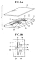
- Figs. 1A to 5B show, in the order of steps, an embodiment of a process for producing a circuit body in terms of a circuit structure according to the present invention.
- a reference numeral 11 designates a vacuum forming die.
- an upper face of the vacuum forming die 11 is a flat forming face 12 which is provided with a plurality of projecting ribs 13.
- the plurality of ribs 13 are fixed and projected on an upper face of the forming face 12 by bonding or threads.
- An arranging recess portion 14 is formed between the opposed ribs 13.
- the arranging recess portion 14 formed by the plurality of ribs 13 is to provide a predetermined arranged shape in terms of a circuit pattern to electric wires 15 (see Figs. 2A and 2B).
- the shown arranging recess portion 14 comprises, a main wiring forming portion 14a in a shape of a straight line and a plurality of branch wiring forming portions 14b perpendicular to the main wiring forming portion 14a, as shown in Fig. 1B.
- the projecting ribs 13 are formed on the forming face 12 and a space between the ribs 13 is utilized as the arranging recess portion 14, so that it is unnecessary to recess the forming face 12 to form the arranging recess portion 14. Therefore, it is advantageous that the arranging recess portion 14 can be formed easily, and the arranging recess portion 14 can be changed easily by exchanging or moving projecting positions of the ribs 13. Also, upper and lower films 19 and 16 are sucked towards the forming face 12 with the films 19 and 16 supported on the projecting ribs 13, and it is possible to provide strength to the upper and lower films 19 and 16.
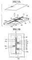
- a plurality of sucking holes 25 are formed on the forming face 12 of the vacuum forming die 11.
- the sucking holes 25 are formed to be scattered outside and inside (the arranging recess portion 14) the opposed ribs 13.
- the upper and lower films 19 and 16 are sucked toward the forming face 12 by a vacuum suction through the sucking holes 25.
- the forming face 12 of the vacuum forming die 11 provided with the projecting ribs 13 is covered with the lower die film 16.
- the lower die film 16 is lightly sucked through the sucking holes 25, and is brought into close contact with the forming face 12.
- the plurality of electric wires 15 are arranged on the vacuum forming die 11. This arrangement is carried out by disposing the plurality of electric wires 15 in the arranging recess portion 14.
- connectors 17 and 18 previously connected to terminal portions of the electric wires 15 are used.
- the connector 17 is previously connected to a terminal of a main wiring 15a of the electric wire 15.
- the connector 18 is previously connected to each of terminal portions of plural branch wirings 15b which branch off from the main wiring 15a.
- the electric wires 15 are arranged in the arranging recess portion 14 so that the connectors 18 arranged on the terminal portions of the branch wirings 15b are positioned in the arranging recess portion 14. More specifically, the connectors 18 arranged on the branch wirings 15b are disposed to be fitted between the ribs 13, the wirings 15b are arranged therebetween.
- Connectors 18 are fitted between the ribs 13 and are provisionally fixed to the ribs 13, so that unexpected displacement of the connectors 18 is limited. Consequently, the connectors 18 do not deviate from proper positions due to the suction and vibration, and are provisionally fixed in the positions with accuracy. As a result, it is possible to fix the connectors 18 to appropriate positions relative to a wire harness 20 produced succeedingly.
- the connector 17 arranged on the main wiring 15a is not fitted between the ribs 13 in the embodiment, but may be fitted between the ribs 13 to be fixed provisionally, similarly to the connectors 18 arranged on the branch wirings 15b.
- the upper die film 19 is put on the electric wires 15 and the forming face 12 and peripheral portion of the upper film 19 is brought into contact with the lower die film 16, as shown in Figs. 3A and 3B. Then, the upper die film 19 is sucked through the sucking holes 25 and is brought into close contact with and bonded to the electric wires 15 and the lower die film 16.
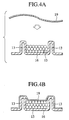
- Figs. 4A and 4B show steps of bonding the upper die film 19 to the lower die film 16.
- a hot-melt adhesive or other adhesives is applied on one or both of the opposed faces of the upper die film 19 and the lower die film 16.
- the vacuum forming die 11 is heated with the films 16 and 19 in close contact with each other, and therefore the upper and lower films 19 and 16 are bonded to each other.
- an arranged shape of the wires 15 is held by the films 19 and 16 to form the wire harness 20.
- the connectors 18 are fixed together with the wire harness 20,and a flat circuit body 23 is formed (see Figs. 5A and 5B).
- a width of the upper die film 19 is set so that the upper film 9 can cover outer peripheral portions of the connectors 18 arranged on the branch wirings 15b, as shown in Fig. 3B. Specifically, the width is set so that the upper film 19 can cover the outer peripheral portions of the connectors 18 except for the end portions 18a of the connectors 18. Therefore, the end portions 18a of the connectors 18 are not covered with the upper die film 19.
- Such an upper die film 19 is bonded to the connectors 18 by the above-described vacuum suction and heating of the vacuum forming die 11.
- the other portion of the upper die film 19 is bonded to the lower die film 16.
- the upper and lower films 19 and 16 are bonded to each other with the connectors 18 interposed therebetween.
- a reference numeral 21 in Figs. 5A and 5B designates connector fixing portions of the film 19.
- the connector fixing portions 21 fix the connectors 18 in proper positions to prevent the connectors 18 from tottering. Therefore, the connectors 18 can be easily fitted to the mating connectors without positioning.
- the connector fixing portions 21 are integrally provided to the outer peripheral portion of the upper die film 19, so that the connector fixing portions 21 integral with the other portion of the upper die film 19 cover and reliably waterproof the terminal portions of the electric wires 15. Therefore, a waterproof treatment for the terminal portions is unnecessary, and the wire harness 20 can be produced easily and speedily.
- the connector fixing portions 21 are not provided to the end portions 18a of the connectors 18, the connector fixing portions 21 do not close connection openings 22 on the side of the end portions 18a. Therefore, the connector fixing portions 21 do not become hindrances to fitting of the mating connectors into the connection openings 22.
- the connectors 18 do not totter because the connectors 18 are fixed to the proper positions by the connector fixing portions 21 provided to the upper and lower die films 19 and 16, and can be easily fitted to the mating connectors. Also, the connectors 18 are integral with the upper and lower films 19 and 16, and the connectors 18 can be reliably waterproofed. Consequently, the waterproof treatment for the terminal portions is unnecessary, and the wire harness 20 can be produced easily.
- the connector fixing portions 21 By forming the connector fixing portions 21 on one of the films 19 and 16, it is possible to treat the other film in a conventional manner, and the connector fixing portions 21 can be formed easily.
- the upper and lower films 19 and 16 are bonded to each other to provide the arrange shape to the electric wires 15, and simultaneously as which, the upper and lower films 19 and 16 are bonded to the outer peripheral portions of the connectors 18 to fix the connectors 18, a step for fixing the connectors 18 is unnecessary, and the connectors 18 can be fixed speedily and easily.
- the connectors 18 are provisionally fixed in the arranging recess portion 14, the connectors 18 are not displaced when they are fixed by bonding the upper and lower films 19 and 16 to each other, and the connectors 18 can be fixed accurately.
- the arranging recess portion 14 can be formed or changed easily.
Landscapes
- Engineering & Computer Science (AREA)
- Mechanical Engineering (AREA)
- Coupling Device And Connection With Printed Circuit (AREA)
- Insulated Conductors (AREA)
- Details Of Indoor Wiring (AREA)
- Multi-Conductor Connections (AREA)
Claims (5)
- Schaltungskörper, welcher aufweist:dadurch gekennzeichnet, dasseinen Kabelbaum (20), der mehrere elektrische Leitungen (15) aufweist, die in einer angeordneten Form angeordnet sind, wobei die elektrischen Leitungen (15) einen Klemmenabschnitt aufweisen;einen Verbinder (18), der auf dem Klemmenabschnitt der elektrischen Leitungen angeordnet ist, wobei der Verbinder (18) einen Außenumfangsabschnitt und einen Endabschnitt (18a) aufweist; undeinen oberen (19) und einen unteren (16) Film (19, 16), die miteinander verbunden sind, mit den elektrischen Leitungen (15) dazwischen, um die elektrischen Leitungen (15) in der angeordneten Form zu halten,
zumindest entweder der obere oder der untere Film (19, 16) einen Verbinderbefestigungsabschnitt (21) aufweist, der mit dem Außenumfangsabschnitt des Verbinders (18) mit Ausnahme von dessen Endabschnitt (18a) verbunden ist, um den Verbinder (18) zu befestigen. - Schaltungskörper nach Anspruch 1, bei welchem der Verbinderbefestigungsabschnitt (21) sowohl auf dem oberen als auch dem unteren Film (19, 16) vorgesehen ist.
- Verfahren zur Herstellung eines Schaltungskörpers mit folgenden Schritten:Anordnen, in einem Anordnungsausnehmungsabschnitt (14) in einer Vakuumform (11), mehrerer elektrischer Leitungen (15), die einen auf einem Verbinder (18) angeordneten Klemmenabschnitt aufweisen, wobei die elektrischen Leitungen (15) zwischen einem oberen Film (19) und einem unteren Film (16) liegen;Anordnen eines Außenumfangsabschhitts des Verbinders (18) abgesehen von dessen Endabschnitt (18a) zwischen dem oberen Film (19) und dem unteren Film (16);Ansaugen mittels Vakuum durch die Vakuumform (11) des oberen Films (19) und des unteren Films (16) aneinander, und um die angeordnete Form der elektrischen Leitungen (15) beizubehalten; undBefestigen des Verbinders (18) zwischen dem oberen Film (19) und dem unteren Film (16) durch einen Verbinderbefestigungsabschnitt (21), der mit dem Außenumfangsabschnitt des Verbinders (18) verbunden wird, abgesehen von dessen Endabschnitt (18a).
- Verfahren zur Herstellung eines Schaltungskörpers nach Anspruch 3, mit dem weiteren Schritt, den Verbinder (18) in dem Anordnungsausnehmungsabschnitt (14) anzuordnen, um provisorisch den Verbinder (18) zu befestigen, wenn die elektrischen Leitungen (15) in der Vakuumform (11) angeordnet werden.
- Verfahren zur Herstellung eines Schaltungskörpers nach Anspruch 3 oder 4, bei welchem die Vakuumform (11) mit vorspringenden Rippen (13) versehen ist, wobei die Rippen (13) zwischen sich einen Raum aufweisen, der als der Anordnungsausnehmungsabschnitt (14) eingesetzt wird.
Applications Claiming Priority (3)
| Application Number | Priority Date | Filing Date | Title |
|---|---|---|---|
| JP9267139A JPH11111065A (ja) | 1997-09-30 | 1997-09-30 | 回路体及びその製造方法 |
| JP26713997 | 1997-09-30 | ||
| JP267139/97 | 1997-09-30 |
Publications (3)
| Publication Number | Publication Date |
|---|---|
| EP0904986A2 EP0904986A2 (de) | 1999-03-31 |
| EP0904986A3 EP0904986A3 (de) | 2001-11-21 |
| EP0904986B1 true EP0904986B1 (de) | 2004-11-24 |
Family
ID=17440629
Family Applications (1)
| Application Number | Title | Priority Date | Filing Date |
|---|---|---|---|
| EP98118470A Expired - Lifetime EP0904986B1 (de) | 1997-09-30 | 1998-09-30 | Schaltungskörper und Verfahren zur Herstellung dieses Schaltungskörpers |
Country Status (4)
| Country | Link |
|---|---|
| US (1) | US6272746B1 (de) |
| EP (1) | EP0904986B1 (de) |
| JP (1) | JPH11111065A (de) |
| DE (1) | DE69827736T2 (de) |
Families Citing this family (18)
| Publication number | Priority date | Publication date | Assignee | Title |
|---|---|---|---|---|
| FR2794085B1 (fr) * | 1999-05-28 | 2001-08-17 | Valeo Climatisation | Tableau de bord de vehicule avec un faisceau electrique |
| DE59907876D1 (de) * | 1999-12-01 | 2004-01-08 | Draexlmaier Lisa Gmbh | Verfahren und Werkzeug zur Herstellung eines Formträgerteils mit darauf fixierten Leitern und Formträgerteil |
| DE10021064A1 (de) * | 2000-04-28 | 2001-11-15 | Bosch Gmbh Robert | Abdeckvorrichtung |
| JP3922565B2 (ja) * | 2002-04-25 | 2007-05-30 | 矢崎総業株式会社 | 回路体の樹脂成形パネル配索方法及び真空成形金型 |
| KR100779336B1 (ko) * | 2002-12-02 | 2007-11-23 | 칼 프로이덴베르크 카게 | 3차원적으로 형성된 평면 케이블 및 그 제조 방법 |
| US20050000632A1 (en) * | 2003-05-23 | 2005-01-06 | Tesa Ag | Method of bonding flat ribbon cables adhesively to substrates such as the interior decorative components of a passenger car, especially roof lining, door side part and boot lid |
| US6946604B1 (en) * | 2003-09-22 | 2005-09-20 | Maris George P | Template for preparing a wire harness |
| CN101616556B (zh) * | 2008-06-27 | 2011-08-31 | 深圳富泰宏精密工业有限公司 | 电子装置的壳体及其制造方法 |
| EP2466702A1 (de) * | 2010-12-14 | 2012-06-20 | Tyco Electronics Nederland B.V. | Verfahren und Vorrichtung zur Herstellung einer Kabelanordnung |
| JP5732901B2 (ja) * | 2011-02-24 | 2015-06-10 | 株式会社オートネットワーク技術研究所 | ワイヤハーネスにおける短絡回路の形成方法 |
| JP2012221916A (ja) * | 2011-04-14 | 2012-11-12 | Auto Network Gijutsu Kenkyusho:Kk | 保護部材付電線 |
| JP2014050283A (ja) * | 2012-09-03 | 2014-03-17 | Yazaki Corp | ハーネスプロテクタ |
| FR3003994B1 (fr) * | 2013-03-26 | 2015-03-20 | Airbus Operations Sas | Dispositif d'aide a la fabrication de harnais electriques |
| US20180093622A1 (en) * | 2016-09-30 | 2018-04-05 | Tony Matijevich | Wire harness with cylinder valve protection |
| US11742113B2 (en) * | 2019-10-28 | 2023-08-29 | The Boeing Company | Form board preparation for wire bundling |
| JP7375726B2 (ja) * | 2020-10-20 | 2023-11-08 | 株式会社オートネットワーク技術研究所 | ドア用配線モジュール及び複合サービスホールカバー |
| JP7543989B2 (ja) * | 2021-06-18 | 2024-09-03 | 株式会社オートネットワーク技術研究所 | 配線モジュール |
| DE102023135189A1 (de) * | 2023-12-14 | 2025-06-18 | Lisa Dräxlmaier GmbH | Verfahren und vorrichtung zur herstellung eines zumindest abschnittsweise bandagierten leitungssatzes für ein bordnetz eines fahrzeugs |
Family Cites Families (9)
| Publication number | Priority date | Publication date | Assignee | Title |
|---|---|---|---|---|
| US3168617A (en) * | 1962-08-27 | 1965-02-02 | Tape Cable Electronics Inc | Electric cables and method of making the same |
| US4319075A (en) * | 1981-01-26 | 1982-03-09 | Amp Inc. | Sealed routing of undercarpet cable |
| JP2682555B2 (ja) * | 1992-05-11 | 1997-11-26 | 矢崎総業株式会社 | フラット回路体の製造方法 |
| JP3144445B2 (ja) * | 1993-01-29 | 2001-03-12 | 矢崎総業株式会社 | フラットワイヤハーネスの製造方法および取付具を備えたフラットワイヤハーネス |
| GB2275373B (en) * | 1993-02-18 | 1996-11-27 | Sumitomo Wiring Systems | Flat harness assembly |
| JP2921551B2 (ja) * | 1994-06-14 | 1999-07-19 | 池田物産株式会社 | フロアカーペットとマットとの融着方法 |
| JP3565951B2 (ja) * | 1995-07-20 | 2004-09-15 | 矢崎総業株式会社 | ワイヤーハーネスおよびその製造方法 |
| JP3249044B2 (ja) * | 1996-06-04 | 2002-01-21 | 矢崎総業株式会社 | ワイヤーハーネス及びその製造方法 |
| US5917151A (en) * | 1997-08-29 | 1999-06-29 | Ut Automotive Dearborn, Inc. | Multi-shot molds for manufacturing wire harnesses |
-
1997
- 1997-09-30 JP JP9267139A patent/JPH11111065A/ja active Pending
-
1998
- 1998-09-29 US US09/161,723 patent/US6272746B1/en not_active Expired - Fee Related
- 1998-09-30 DE DE69827736T patent/DE69827736T2/de not_active Expired - Fee Related
- 1998-09-30 EP EP98118470A patent/EP0904986B1/de not_active Expired - Lifetime
Also Published As
| Publication number | Publication date |
|---|---|
| DE69827736D1 (de) | 2004-12-30 |
| US6272746B1 (en) | 2001-08-14 |
| DE69827736T2 (de) | 2005-11-03 |
| EP0904986A3 (de) | 2001-11-21 |
| JPH11111065A (ja) | 1999-04-23 |
| EP0904986A2 (de) | 1999-03-31 |
Similar Documents
| Publication | Publication Date | Title |
|---|---|---|
| EP0904986B1 (de) | Schaltungskörper und Verfahren zur Herstellung dieses Schaltungskörpers | |
| EP1157892B1 (de) | Kabelbaumverbindung | |
| US5962813A (en) | Connection structure of flat cable to terminals | |
| JP2003168327A (ja) | フラット配線材と積層配線材 | |
| US5645441A (en) | Rotary connector device | |
| CN112956040B (zh) | 汇流条组件及其制造方法 | |
| JP3698030B2 (ja) | ジャンクションボックスおよびジャンクションボックスの組立方法 | |
| KR20150023488A (ko) | 차량 부품 지지체 및 그 제조 방법 | |
| US6018127A (en) | Wire connection structure | |
| JP3109720B2 (ja) | 電気接続箱 | |
| JP3416001B2 (ja) | 半導体装置の製造方法 | |
| JP4218852B2 (ja) | 回路ユニット | |
| JPH11195327A (ja) | ワイヤハーネス及びその製造方法 | |
| JP3745446B2 (ja) | フラット回路体の製造方法及び真空成形型 | |
| JPH09306261A (ja) | ワイヤーハーネスの真空成形方法及びこの方法で成形したワイヤーハーネス | |
| JPH10261327A (ja) | ワイヤーハーネス | |
| JP2746965B2 (ja) | 金属基板を有する集積回路のコネクタ構造 | |
| JPH11219739A (ja) | バスバー電気接続部構造 | |
| JP2751104B2 (ja) | 半導体装置用リードフレームの製造方法 | |
| JP3281832B2 (ja) | 電気接続具 | |
| US5887342A (en) | Method for making an electronic control unit | |
| JP3003691B1 (ja) | コネクタカバー | |
| JP2914190B2 (ja) | 電気接続箱 | |
| JPH03104296A (ja) | 金属基板を有する集積回路 | |
| JPH05135632A (ja) | フラツトワイヤハーネスの製造方法 |
Legal Events
| Date | Code | Title | Description |
|---|---|---|---|
| PUAI | Public reference made under article 153(3) epc to a published international application that has entered the european phase |
Free format text: ORIGINAL CODE: 0009012 |
|
| 17P | Request for examination filed |
Effective date: 19980930 |
|
| AK | Designated contracting states |
Kind code of ref document: A2 Designated state(s): AT BE CH CY DE DK ES FI FR GB GR IE IT LI LU MC NL PT SE Kind code of ref document: A2 Designated state(s): DE FR GB |
|
| AX | Request for extension of the european patent |
Free format text: AL;LT;LV;MK;RO;SI |
|
| PUAL | Search report despatched |
Free format text: ORIGINAL CODE: 0009013 |
|
| AK | Designated contracting states |
Kind code of ref document: A3 Designated state(s): AT BE CH CY DE DK ES FI FR GB GR IE IT LI LU MC NL PT SE |
|
| AX | Request for extension of the european patent |
Free format text: AL;LT;LV;MK;RO;SI |
|
| AKX | Designation fees paid |
Free format text: DE FR GB |
|
| 17Q | First examination report despatched |
Effective date: 20030904 |
|
| GRAP | Despatch of communication of intention to grant a patent |
Free format text: ORIGINAL CODE: EPIDOSNIGR1 |
|
| GRAS | Grant fee paid |
Free format text: ORIGINAL CODE: EPIDOSNIGR3 |
|
| GRAA | (expected) grant |
Free format text: ORIGINAL CODE: 0009210 |
|
| AK | Designated contracting states |
Kind code of ref document: B1 Designated state(s): DE FR GB |
|
| REG | Reference to a national code |
Ref country code: GB Ref legal event code: FG4D |
|
| REF | Corresponds to: |
Ref document number: 69827736 Country of ref document: DE Date of ref document: 20041230 Kind code of ref document: P |
|
| PG25 | Lapsed in a contracting state [announced via postgrant information from national office to epo] |
Ref country code: GB Free format text: LAPSE BECAUSE OF NON-PAYMENT OF DUE FEES Effective date: 20050930 |
|
| PLBE | No opposition filed within time limit |
Free format text: ORIGINAL CODE: 0009261 |
|
| STAA | Information on the status of an ep patent application or granted ep patent |
Free format text: STATUS: NO OPPOSITION FILED WITHIN TIME LIMIT |
|
| ET | Fr: translation filed | ||
| 26N | No opposition filed |
Effective date: 20050825 |
|
| PG25 | Lapsed in a contracting state [announced via postgrant information from national office to epo] |
Ref country code: DE Free format text: LAPSE BECAUSE OF NON-PAYMENT OF DUE FEES Effective date: 20060401 |
|
| GBPC | Gb: european patent ceased through non-payment of renewal fee |
Effective date: 20050930 |
|
| PG25 | Lapsed in a contracting state [announced via postgrant information from national office to epo] |
Ref country code: FR Free format text: LAPSE BECAUSE OF NON-PAYMENT OF DUE FEES Effective date: 20060531 |
|
| REG | Reference to a national code |
Ref country code: FR Ref legal event code: ST Effective date: 20060531 |