EP0901046B1 - Révélateur et procédé de formation d'image - Google Patents
Révélateur et procédé de formation d'image Download PDFInfo
- Publication number
- EP0901046B1 EP0901046B1 EP98116768A EP98116768A EP0901046B1 EP 0901046 B1 EP0901046 B1 EP 0901046B1 EP 98116768 A EP98116768 A EP 98116768A EP 98116768 A EP98116768 A EP 98116768A EP 0901046 B1 EP0901046 B1 EP 0901046B1
- Authority
- EP
- European Patent Office
- Prior art keywords
- toner
- image
- weight
- electrostatic latent
- resin
- Prior art date
- Legal status (The legal status is an assumption and is not a legal conclusion. Google has not performed a legal analysis and makes no representation as to the accuracy of the status listed.)
- Expired - Lifetime
Links
Images


Classifications
-
- G—PHYSICS
- G03—PHOTOGRAPHY; CINEMATOGRAPHY; ANALOGOUS TECHNIQUES USING WAVES OTHER THAN OPTICAL WAVES; ELECTROGRAPHY; HOLOGRAPHY
- G03G—ELECTROGRAPHY; ELECTROPHOTOGRAPHY; MAGNETOGRAPHY
- G03G9/00—Developers
- G03G9/08—Developers with toner particles
- G03G9/087—Binders for toner particles
- G03G9/08742—Binders for toner particles comprising macromolecular compounds obtained otherwise than by reactions only involving carbon-to-carbon unsaturated bonds
- G03G9/08757—Polycarbonates
-
- G—PHYSICS
- G03—PHOTOGRAPHY; CINEMATOGRAPHY; ANALOGOUS TECHNIQUES USING WAVES OTHER THAN OPTICAL WAVES; ELECTROGRAPHY; HOLOGRAPHY
- G03G—ELECTROGRAPHY; ELECTROPHOTOGRAPHY; MAGNETOGRAPHY
- G03G15/00—Apparatus for electrographic processes using a charge pattern
- G03G15/06—Apparatus for electrographic processes using a charge pattern for developing
- G03G15/08—Apparatus for electrographic processes using a charge pattern for developing using a solid developer, e.g. powder developer
-
- G—PHYSICS
- G03—PHOTOGRAPHY; CINEMATOGRAPHY; ANALOGOUS TECHNIQUES USING WAVES OTHER THAN OPTICAL WAVES; ELECTROGRAPHY; HOLOGRAPHY
- G03G—ELECTROGRAPHY; ELECTROPHOTOGRAPHY; MAGNETOGRAPHY
- G03G9/00—Developers
- G03G9/08—Developers with toner particles
- G03G9/087—Binders for toner particles
- G03G9/08784—Macromolecular material not specially provided for in a single one of groups G03G9/08702 - G03G9/08775
- G03G9/08795—Macromolecular material not specially provided for in a single one of groups G03G9/08702 - G03G9/08775 characterised by their chemical properties, e.g. acidity, molecular weight, sensitivity to reactants
Definitions
- This invention relates to a toner for forming toner images in image forming processes such as electrophotography, electrostatic printing, magnetic recording and toner jet recording, and an image forming method employing such a toner. More particularly, this invention relates to a toner for developing electrostatic images which is used in a fixing system in which visible images formed out of toner are heat-fixed to recording mediums, and an image forming method employing such a toner.
- a photosensitive member such as a photosensitive drum is electrostatically uniformly charged by means of a primary charging assembly, and imagewise exposure is carried out using laser light modulated by magenta image signals of an original, to form an electrostatic latent image on the photosensitive drum.
- the electrostatic latent image is developed by means of a magenta developing assembly holding a magenta toner, to form a magenta toner image.
- the magenta toner image developed on the photosensitive drum is transferred by a direct or indirect means by means of a transfer charging assembly.
- the photosensitive drum on which the electrostatic latent image has been developed is decharged by a residual charge eliminator, and is further cleaned through a cleaning means. Thereafter, it is again electrostatically charged by the primary charging assembly, and a cyan toner image is similarly formed.
- the cyan toner image is transferred to the recording medium on which the magenta toner image has been transferred, and then a yellow toner image and a black toner image are successively formed and developed so that the four color toner images are transferred to the recording medium.
- the recording medium having these four color toner images is passed through a fixing roller so that they are fixed to the recording medium by the action of heat and pressure. Thus, a full-color image is formed.
- toners used in the color image forming process it is preferable to use toners having good melt properties and color-mixing properties when heat is applied thereto and also having a low softening point and high sharp-melt properties in a low melt viscosity.
- Color toners having such high sharp-melt properties is so high in affinity for the fixing roller that it tends to cause offset with respect to the fixing roller at the time of fixing.
- the roller surface is formed out of a material, such as silicon rubber or a fluorine resin, having an excellent releasability to toner, and, in order to prevent offset and to prevent fatigue of the roller surface, its surface is further covered with a thin film formed using a fluid having a high releasability as exemplified by silicone oil or fluorine oil.
- a fluid having a high releasability as exemplified by silicone oil or fluorine oil.
- this method is very effective in view of the prevention of the offset of toner, it requires a device for feeding an anti-offset fluid, and hence has such a problem that a complicated fixing assembly is required.
- the application of oil may bring about separation of layers on the fixing roller, and consequently, shorten the lifetime of the fixing roller.
- Japanese Patent Publications No. 52-3304 and No. 3305 and Japanese Patent Application Laid-open No. 57-52574 disclose that as the release agent a wax is incorporated into toner particles.
- Japanese Patent Applications Laid-open No. 3-50559, No. 2-79860, No. 1-109359, No. 62-14166, No. 61-273554, No. 61-94062, No. 61-138259, No. 60-252361, No. 60-252360 and No. 60-217366 disclose techniques for incorporating waxes.
- release agents having a relatively high crystallizability as typified by polyethylene wax and polypropylene wax can be used in order to improve high-temperature anti-offset properties at the time of fixing.
- this crystallizability of release agents may cause great damage to the transparency of OHP (overhead projector) toner images when outputted.
- the wax may cause a lowering of blocking resistance of toners, and a lowering of developing performance because of migration of wax toward toner particle surfaces when toners are exposed to heat as a result of temperature rise in image forming apparatus such as printers and copying machines and also when toners are left standing for a long term.
- binder resin More specifically, a cross-linking component or a high-molecular-weight component is used in a binder resin in a larger quantity so that the high-temperature anti-offset properties at the time of fixing can be improved.
- This method can certainly improve high-temperature anti-offset properties to a certain extent and also can be effective for improving durability such that external additives are prevented from being buried in toner particle surfaces and toners are prevented from melt-adhereing to the photosensitive member and toner carrying member.
- a toner produced by suspension polymerization is proposed (Japanese Patent Publication No. 36-10231).
- polymerizable monomers and a colorant and also optionally a polymerization initiator, a cross-linking agent, a charge control agent and other additives
- a monomer composition is dispersed in a continuous phase (e.g., an aqueous phase) containing a dispersion stabilizer, by means of a suitable stirrer to simultaneously carry out polymerization reaction to obtain toner particles having the desired particle diameters.
- droplets of the monomer composition are produced in a dispersion medium having a large polarity such as water, and hence what is called core/shell structure can be formed in which components having polar groups, contained in the monomer composition, tend to present at the surface layer portions which are interfaces with the aqueous phase and non-polar components are not present at the surface layer portions.
- the toner produced by polymerization makes it possible to achieve both the low-temperature fixing performance or blocking resistance and the high-temperature anti-offset properties and also makes it possible to prevent high-temperature offset without applying any oil release agent to the fixing roller.
- Toners for developing electrostatic images commonly contain a binder resin and a colorant as essential components, and various methods for improving binder resins are proposed for the purpose of improving the developing performance, fixing performance, storage stability and environmental stability of toners.
- a method is presented in which shells of a resin having a relatively low glass transition temperature (Tg) are covered with a resin having a relatively high Tg in order to achieve both the low-temperature fixing performance and the storage stability (e.g., Japanese Patent Application Laid-open No. 5-197203).
- Tg glass transition temperature
- most resins having a relatively high Tg which are used therein are polar resins having a moisture absorption, such as polyesters. Even though such resins can achieve both the low-temperature fixing performance and the storage stability, they have often caused a problem on charging stability resistant to environment variations.
- toners are commonly known to undergo deterioration caused by external additives that may be buried in toner particle surfaces when images are printed on many sheets, to adversely affect the images.
- a method is available in which the binder resin is made to have a higher mechanical strength. Since, however, problems may actually arise on the grindability of the binder resin and the fixing performance of toners, it is commonly difficult to use such a tough resin as a binder resin.
- polycarbonates As resins having superior mechanical strength, electrical characteristics and aging resistance (weatherability), polycarbonates are commonly widely known and are used in various purposes. Some methods in which polycarbonates are used as binder resins are disclosed also in respect of toners.
- Japanese Patent Application Laid-open No. 46-28588 discloses an image forming method making use of a specific polycarbonate copolymer and a granular carrier.
- a toner having a superior blocking resistance can be obtained by using a specific polycarbonate copolymer as the binder resin.
- a polycarbonate copolymer having a glass transition temperature of from 70 to 95°C is used as the binder resin and also any wax component is not contained in the toner, resulting in a very poor low-temperature fixing performance.
- the publication also has no description as to any influence on electrophotographic performance that may be caused by impurities contained in the polycarbonate copolymer.
- the publication still also discloses, in Examples, processes for producing toners by spray drying and pulverization, but has no disclosure at all as to differences in transfer performance of toner images from the electrostatic latent image bearing member to the recording medium and differences in charging uniformity, which are ascribable to the shapes of the toners obtained.
- Japanese Patent Application Laid-open No. 63-208863 discloses a method in which a polycarbonate terpolymer with a specific structure, having a glass transition temperature of about 50°C, is used as a binder resin of a toner for flash fixing.
- the toner can be free from any bad smell and eluted matter because the binder resin polycarbonate terpolymer does not thermally decompose during flash fixing, and a toner having a good fixing performance can be obtained even though it contains no wax component.
- the toner since only the polycarbonate terpolymer having a low glass transition temperature is used as the binder resin, the toner has not reached satisfactory levels in respect of blocking resistance and running performance.
- the toner is one designed for flash fixing, it is difficult for the toner to be applied to a type of fixing assembly, e.g., in which the toner comes into contact with a heating element as in heat-roll fixing.
- U.S. Patent No. 4,457,998 also discloses a toner having a structure wherein a linear binder resin is incorporated in a binder resin cross-linked in a high degree, and states that a polycarbonate copolymer can be used as the highly cross-linked resin or the linear binder resin or as both of the two.
- a polycarbonate copolymer can be used as the highly cross-linked resin or the linear binder resin or as both of the two.
- Japanese Patent Application Laid-Open No. 5-273782 discloses that filming can be prevented by using a toner with a value of Izot impact strength of 2 to 500 kg.cm/cm when made into a plate in an image forming method using a developing roller in which many minute closed electric fields are formed near the surface of the developing roller. It is said that a mixture of styrene-acrylic resin and polycarbonate may be used as a binder resin for the toner. However, in this publication, there is no description about polycarbonate.
- Japanese Patent Application Laid-open No. 6-43688 discloses a method in which a polycarbonate copolymer having a specific structure that exhibits thermotropic liquid-crystal properties is used as a binder resin.
- the polycarbonate copolymer that exhibits thermotropic liquid-crystal properties usually has a high crystallizability, shows a gentle heat softening behavior up to its melting point, and further abruptly liquefies (melts) upon temperature rise to cause a decrease in viscosity and a drop in temperature. Because of such properties, the toner in which such a polycarbonate copolymer is used as the binder resin, even though it contains no wax component, can be fixed at a low energy while maintaining the grindability and blocking resistance.
- the toner disclosed in this publication is constituted only of one kind of binder resin, the toner is so low in a viscosity at the time of its melting that what is called high-temperature offset is brought about, where the molten toner adheres to fixing members such as heat rolls. Such a problem remains unsettled.
- the publication has no specific description as to any influence on electrophotographic performance that may be caused by impurities contained in the polycarbonate copolymer and as to the shape of toner particles.
- the rear end of the recording medium may cause faulty attraction because of a strong stiffness of the recording medium, consequently undesirably causing faulty images ascribable to transfer. Similar faulty images may also occur on the small-sized sheets of paper.
- This surface layer may locally cause breakdown to undesirably cause a conspicuous image disorder in halftone images where the toner is laid in a smaller quantity.
- high humidity which is higher than 60%RH (relative humidity)
- 60%RH relative humidity
- 40%RH relative humidity
- the toners on the intermediate transfer member are in a larger quantity than that in black-and-white copying and necessarily remain as transfer residual toners in a larger quantity.
- the melt-adhesion or filming of toner tends to occur on the surface of the intermediate transfer member, so that transfer efficiency may become poor and problems on color uniformity and color balance tend to occur because of four color toner images not uniformly transferred in full-color copying.
- the toners on the photosensitive member are in a larger quantity than a monochromatic black toner used in black-and-white copying machines, and it is difficult to improve the transfer efficiency only by using conventional toners.
- the melt-adhesion or filming of toners may occur on the surfaces of the photosensitive member and intermediate transfer member because of the shear force or rubbing force acting between the photosensitive member or intermediate transfer member and the cleaning member and/or between the photosensitive member and the intermediate transfer member, so that the transfer efficiency may become poor and problems on color uniformity and color balance tend to occur because of four color toner images not uniformly transferred in full-color copying.
- toners set in usual full-color copying machines all the color toners are required to be well color-mixed in the step of fixing. From this viewpoint, the improvement of color reproducibility and the transparency of OHP images are important, and, compared with black toners, it is commonly preferable to use in color toners sharp-melt and low-molecular weight resins.
- release agents having a relatively high crystallizability as typified by polyethylene wax and polypropylene wax are used in order to improve the high-temperature anti-offset properties at the time of fixing.
- Japanese Patent Applications Laid-open No. 59-133573 named are No. 62-203182, No. 63-133179, No. 64-20587, No. 2-302772, No. 5-2289, No. 5-53482 and No. 5-61383. None of these, however, refer to any desirable toner composition.
- a cleaning-at-development system (or cleaning-cum-development) having substantially no cleaning assembly
- Any conventional toners attaching importance to fixing performance can not well solve such problems.
- it is also sought to provide a technique that can achieve both fixing performance and running performance of toners.
- Japanese Patent Application Laid-open No. 7-281485 discloses a technique of a polymerization toner having the effect of restraining the deterioration of the toner carrying member surface and the deterioration of the photosensitive member surface.
- resins used therein are those commonly available, and the publication does not mention at all any influence coming from the composition of resin. It also has no disclosure relating to the compatibility with fixing performance.
- Japanese Patent Application Laid-open No. 8-305074 discloses a cleanerless image forming method making use of a toner having a specific particle shape and having 1,000 ppm or less of residual monomers. There, however, is room for further improvement in relation to the adhesion of toner to the surface of the photosensitive member or toner carrying member.
- An object of the present invention is to provide a toner solving the problems arising in prior art, and an image forming method employing such a toner.
- Another object of the present invention is to provide a toner for developing electrostatic images which has a high running performance and a high transfer efficiency, and an image forming method employing such a toner.
- Still another object of the present invention is to provide a toner for developing electrostatic images which may less vary in charging performance depending on environment and has a high transfer efficiency, and an image forming method employing such a toner.
- a further object of the present invention is to provide an image forming method that can greatly improve running performances (or durability) such as resistance to toner deterioration and resistance to melt-adhesion of toner while maintaining low-temperature fixing performance by using a special toner in a contact development type image forming process employing a cleanerless system or an intermediate transfer member.
- the present invention provides a toner as defined in claim 1.
- the present invention also provides an image forming method as defined in claim 19.
- a toner having a good running performance and a good transfer efficiency can be obtained by using a polycarbonate resin as part of a binder resin and also controlling the content of a specific compound contained in the toner. Thus, they have accomplished the present invention.
- the toner according to the present invention is constituted of at least a binder resin, a colorant and a wax component and to contain a polycarbonate resin as the binder resin.
- the polycarbonate resin the essential component in the present invention, has in its molecular structure a repeating unit represented by the following Formula (I) wherein R represents an organic group.
- the repeating unit represented by the above Formula (I) includes those having various structures. All known polycarbonates produced by, e.g., allowing divalent phenols to react with carbonate precursors by a solution process or a melting process. For example, it may include polymers having a repeating unit represented by the following Formula (II) wherein R 2 represents a hydrogen atom, an aliphatic hydrocarbon group or an aromatic substituent, m represents an integer of 0 to 4, and when R 2 is in plurality, they may be the same or different; and Z represents a linkage represented by a single bond, an aliphatic hydrocarbon group, an aromatic substituent, -S-, -SO-, -SO 2 -, -O- or -CO-.
- Formula (II) wherein R 2 represents a hydrogen atom, an aliphatic hydrocarbon group or an aromatic substituent, m represents an integer of 0 to 4, and when R 2 is in plurality, they may be the same or different; and Z represents a linkage represented
- This polycarbonate resin is available from various, routes. Usually, it can be readily produced by allowing a divalent phenol represented by any of Formulas (III) to (V): wherein R 2 represents a hydrogen atom, an aliphatic hydrocarbon group or an aromatic substituent, m represents an integer of 0 to 4, and when R 2 is in plurality, they may be the same or different; and Z represents a linkage represented by a single bond, an aliphatic hydrocarbon group, an aromatic substituent, -S-, -SO-, -SO 2 -, -O- or -CO-; to react with a carbonate precursor such as phosgene or a carbonate compound.
- the divalent phenol can be produced by, e.g., allowing the divalent phenol to react with a carbonate precursor such as phosgene or subjecting the divalent phenol and a carbonate precursor such as diphenyl carbonate to transesterification, in a solvent such as methylene chloride in the presence of a known acid acceptor or molecular weight modifier.
- a carbonate precursor such as phosgene
- a carbonate precursor such as diphenyl carbonate
- the divalent phenols represented by the above Formulas (III) to (V) may include various ones, and may include 2,2-bis(4-hydroxyphenyl)propane (commonly called "bisphenol A"), and also dihydroxyarylalkanes such as bis(4-hydroxyphenyl)methane, bis(4-hydroxyphenyl)phenylmethane, bis(4-hydroxyphenyl)naphthylmethane, bis(4-hydroxyphenyl)-(4-isopropylphenyl)methane, bis(3,5-diemthyl-4-hydroxyphenyl)methane, 1,1-bis(4-hydroxyphenyl)ethane, 1-naphthyl-1,1-bis(4-hydroxyphenyl)ethane, 1-phenyl-1,1-bis(4-hydroxyphenyl)ethane, 1,2-bis(4-hydroxyphenyl)ethane, 2-methyl-1,1-bis(4-hydroxyphenyl)propan
- the carbonate compound may include diaryl carbonates such as diphenyl carbonate, and dialkyl carbonates such as dimethyl carbonate and diethyl carbonate.
- the polycarbonate resin used in the present invention may be used in the form of a homopolymer making use of one of these divalent phenols, a copolymer making use of two or more of them, or a blend of any of these. It may also be a thermoplastic random-branched polycarbonate resin obtained by allowing a polyfunctional aromatic compound to react with the above divalent phenol and/or carbonate precursor.
- a modified polycarbonate resin which has such a form that part of the above divalent phenol has been replaced with a polyhydric alcohol such as ethylene glycol, diethylene glycol, triethylene glycol, 1,2-propylene glycol, 1,3-propylene glycol, 1,4-butanediol, neopentyl glycol, 1,4-bis(hydroxymethyl)cyclohexane, 1,4-bis(2-hydroxyethyl)benzene, 1,4-cyclohexanedimethanol, polyethylene glycol, propylene glycol, hydrogenated bisphenol A or a derivative thereof, an ethylene oxide addition product of bisphenol A, a propylene oxide addition product of bisphenol A, glycerol, trimethylolpropane, or pentaerythritol.
- a polyhydric alcohol such as ethylene glycol, diethylene glycol, triethylene glycol, 1,2-propylene glycol, 1,3-propylene glycol, 1,4-butanediol
- the divalent phenol may be produced simply by replacement of part of the divalent phenol by the use of the above process.
- a method may be used in which the divalent phenol is reacted with an aliphatic or aromatic bischloroformate in a methylene chloride solvent using pyridine as a catalyst.
- pyridine as a catalyst.
- it may be synthesized by any production process other than these.
- the polycarbonate resin it is also possible to use a block copolymer of the above polycarbonate with a polymer such as polystyrene, styrene-acrylic or methacrylic copolymer, polyester, polyurethane, epoxy resin, polyolefin, polyamide, polysulfone, polycyanoaryl ether or polyarylene sulfide, and a graft-modified copolymer obtained by grafting an alkyl acrylate or methacrylate monomer, an acrylic or methacrylic acid monomer, a maleic acid monomer or a styrene monomer.
- a polymer such as polystyrene, styrene-acrylic or methacrylic copolymer, polyester, polyurethane, epoxy resin, polyolefin, polyamide, polysulfone, polycyanoaryl ether or polyarylene sulfide, and a graft-modified copolymer obtained by
- a component having in its structure a repeating unit of the polycarbonate resin, contained in components having a molecular weight of 1,000 or less, is contained in an amount of 5.0% by weight or less based on the weight of the toner.
- impurities contained in polycarbonate resins may differ in types depending on the types of the polycarbonate resin and their production process, and may include various compounds such as starting materials for the polycarbonate resins, auxiliary starting materials, by-products, decomposition products of these, polymerization catalysts, polymerization terminators, polymerization solvents and antioxidants.
- they are chlorinated aliphatic or aromatic hydrocarbons (e.g., dichloromethane), phosgene, phenol, t-butylphenol, organic amines, sodium chloride, aromatic compounds having two or more hydroxyl groups per molecule [e.g., divalent phenols used as monomers of the polycarbonate resin, such as 2,2-bis(3-methyl-4-hydroxyphenyl)propane], aliphatic compounds having two or more hydroxyl groups per molecule (e.g., diols used as monomers of the polycarbonate resin, such as 1,4-butanediol), polycarbonate oligomers, compounds formed by ester linkage of a compound having two or more hydroxyl groups per molecule and a polymerization terminator with a carbonic acid intervening therebeween (e.g., compounds formed by ester linkage of a divalent phenol and p-tert-butylphenol with a carbonic acid intervening therebetween), mono- and
- low-boiling compounds such as dichloromethane and water-soluble compounds such as sodium chloride can be removed relatively with ease in the steps of producing the polycarbonate resin.
- monomers having two or more hydroxyl groups per molecule e.g., divalent phenols
- components having repeating units of the polycarbonate resin in the structure and having molecular weight of 1,000 or less i.e., the polycarbonate oligomers or the compounds formed by ester linkage of a compound having two or more hydroxyl groups per molecule and a polymerization terminator such as a monovalent phenol with a carbonic acid intervening therebetween
- the toners may cause a variety of serious problems such as a lowering of charge quantity of toner (a decrease in image density and an increase in fog), a lowering of environmental stability of toner, a coloring (a change in color of images) due to aerial oxidation of phenol type impurities, a bad smell of impurities at the time of fixing, a lowering of OHP transparency that is caused by crystallization of impurities, an unexpected cross-linking of binder resin in the step of melt-kneading which is one of toner production steps in a pulverization process, and a polymerization inhibitory action caused by phenol type impurities when toners are produced by polymerization.
- the toner of the present invention is so controlled that, in molecular weight distribution as measured by GPC of THF-soluble matter, the component having in its structure a repeating unit of the polycarbonate resin, contained in the components having a molecular weight of 1,000 or less, i.e., the component having a repeating unit of the polycarbonate resin in the structure and having a molecular weight of 1,000 or less, is in an amount of 5.0% by weight or less based on the weight of the toner.
- the compounds that may adversely affect various performances and properties of toners include not only the component having a repeating unit of the polycarbonate resin in the structure and having a molecular weight of 1,000 or less, but also the monomers of the polycarbonate resin.
- the content of such monomers has a proportionality to the content of the component having a repeating unit of the polycarbonate resin in the structure and having a molecular weight of 1,000 or less, and the above various problems do not occur so long as the content of the component having a repeating unit of the polycarbonate resin in the structure and having a molecular weight of 1,000 or less is kept not more than 5.0% by weight based on the weight of the toner. This has been found as a result of extensive studies made by the present inventors.
- the binder resin a polycarbonate resin purified by re-precipitation so highly that the component having a repeating unit of the polycarbonate resin in the structure and having a molecular weight of 1,000 or less is not detected at all even if the toner is analyzed in various manners.
- the component having in its structure a repeating unit of the polycarbonate resin, contained in components having a molecular weight of 1,000 or less, is contained in the toner in an amount more than 15.0% by weight, the durability of the toner is lowered, storage stability is deteriorated, and change in image density comes to be large when many sheets are printed out, and in addition, a transfer efficiency variation due to environmental change and fogging are increased.
- the component having in its structure a repeating unit of the polycarbonate resin, contained in components having molecular weight of 1,000 or less, in molecular weight distribution as measured by GPC of THF-soluble matter can be qualitatively and quantitatively analyzed by various methods.
- the toner may be analyzed by spectroscopy such as nuclear magnetic resonance spectroscopy ( 1 H-NMR, 13 C-NMR), infrared absorption spectroscopy (IR), Raman spectroscopy, ultraviolet absorption spectroscopy (UV) or mass spectroscopy (MS), elementary analysis, GPC, gas chromatography (GC), high-pressure liquid chromatography (HPLC), and other chemical analyses.
- spectroscopy such as nuclear magnetic resonance spectroscopy ( 1 H-NMR, 13 C-NMR), infrared absorption spectroscopy (IR), Raman spectroscopy, ultraviolet absorption spectroscopy (UV) or mass spectroscopy (MS), elementary analysis, GPC, gas chromatography (GC), high-pressure liquid chromatography (HP
- the toner When it is difficult for the toner to be analyzed by itself, the toner may be subjected to Soxhlet extraction with a solvent capable of dissolving binder resin, such as tetrahydrofuran or toluene, the filtrate obtained may be concentrated with an evaporator, and thereafter the above analysis may be made.
- a solvent capable of dissolving binder resin such as tetrahydrofuran or toluene
- the filtrate obtained may be concentrated with an evaporator, and thereafter the above analysis may be made.
- Various analytical means may also be employed; e.g., a sample of the components having molecular weight of 1,000 or less, separated and collected by liquid chromatography or GPC, or a sample extracted with a single or mixed solvent may be analyzed by the above method. Any of these analytical means may be used alone, or in combination.
- Another method is also available in which the components having molecular weight of 1,000 or less contained in the toner are separated and collected by GPC, the components thus collected are completely hydrolyzed with, e.g., an alkali, and thereafter the monomers having two or more hydroxyl groups in the molecule (e.g., divalent phenols) used when the polycarbonate resin is produced are qualitatively and quantitatively analyzed by the analytical means such as 1 H-NMR, 13 C-NMR or IR.
- the analytical means such as 1 H-NMR, 13 C-NMR or IR.
- the content of the monomers quantitated here is the sum total of monomers produced by hydrolysis of the polycarbonate oligomers having molecular weight of 1,000 or less and the compounds formed by ester linkage of a compound having two or more hydroxyl groups per molecule and a polymerization terminator such as a monovalent phenol with a carbonic acid intervening therebetween, and residual monomers originally contained in the polycarbonate resin (at the time of polymerization).
- This total content is calculated as the content of the polycarbonate oligomers and the compounds formed by ester linkage of a monomer and a polymerization terminator with a carbonic acid intervening therebetween (after the polymerization terminator has been qualitatively and quantitatively analyzed separately).
- the molecular weight distribution of the THF-soluble matter of the toner is measured by gel permeation chromatography (GPC).
- GPC gel permeation chromatography
- a solution prepared by dissolving the binder resin or toner in tetrahydrofuran (THF) at room temperature over a period of 24 hours is filtered with a solvent-resistant membrane filter of 0.2 ⁇ m in pore diameter to obtain a sample solution, which is then measured under conditions shown below.
- THF tetrahydrofuran
- the amount of THF is so controlled that the component soluble in THF is in a concentration of from 0.4 to 0.6% by weight.
- a molecular weight calibration curve is used which is prepared using a standard polystyrene resin (available from Toso Co., Ltd., TSK Standard Polystyrene F-850, F-450, F-288, F-128, F-80, F-40, F-20, F-10, F-4, F-2, F-1, A-5000, A-2500, A-1000, A-500).
- a standard polystyrene resin available from Toso Co., Ltd., TSK Standard Polystyrene F-850, F-450, F-288, F-128, F-80, F-40, F-20, F-10, F-4, F-2, F-1, A-5000, A-2500, A-1000, A-500).
- the polycarbonate resin may preferably be those having a peak molecular weight in the region of molecular weight of from 1,000 to 500,000, and more preferably in the region of molecular weight of from 2,000 to 100,000, in molecular weight distribution as measured by gel permeation chromatography (GPC). If it has a peak molecular weight in the region of molecular weight lower than 1,000, it may adversely affect charging performance, and, in the region of molecular weight higher than 500,000, its melt viscosity may be so high as to cause a problem on fixing performance.
- a suitable molecular weight regulator, a branching agent for improving viscoelasticity and a catalyst for accelerating reaction may optionally be used.
- the polycarbonate resin may be in a content of from 0.1 to 50% by weight, preferably from 0.2 to 40% by weight, and more preferably from 0.5 to 30% by weight, based on the weight of the binder resin, and an additional resin used as the binder resin in combination with the polycarbonate resin may be in a content of from 50 to 99.9% by weight, preferably from 60 to 99.8% by weight, and more preferably from 70 to 99.5% by weight.
- a high-molecular-weight resin or cross-linked resin having a peak molecular weight higher than 50,000 and a low-molecular-weight resin of about a peak molecular weight of from 1,000 to 50,000 may preferably be used in combination as binder resins so that the viscoelasticity of the toner can be designed so as to prevent low-temperature and high-temperature offset.
- the polycarbonate resin in the binder resin is in a content more than 50% by weight, it may be difficult to produce the toner so designed, causing a problem. If on the other hand the polycarbonate resin in the binder resin is in a content less than 0.1% by weight, the superior running performance and transfer efficiency which should be achieved by the present invention can not be realized.
- the additional resin used in the present invention in combination with the polycarbonate resin may include styrene-acrylic resins, polyester resins, styrene-butadiene resins and epoxy resins which are commonly used.
- styrene-acrylic resins and polyester resins and epoxy resins may preferably be used.
- These resins may be produced by any known methods. For example, styrene-acrylic resins can be obtained by polymerizing monomers for forming them.
- styrene monomers such as styrene, o-, m- or p-methylstyrene, and m- or p-ethylstyrene
- acrylate or methacrylate monomers such as methyl acrylate or methacrylate, ethyl acrylate or methacrylate, propyl acrylate or methacrylate, butyl acrylate or methacrylate, octyl acrylate or methacrylate, dodecyl acrylate or methacrylate, stearyl acrylate or methacrylate, behenyl acrylate or methacrylate, 2-ethylhexyl acrylate or methacrylate, dimethylaminoethyl acrylate or methacrylate, and diethylaminoethyl acrylate or methacrylate; and olefin monomers such as butadiene, isoprene, cyclopentyl
- any of these may be used alone, or usually used in the form of an appropriate mixture of monomers so mixed that the theoretical glass transition temperature (Tg) as described in a publication POLYMER HANDBOOK, 2nd Edition III, pp.139-192 (John Wiley & Sons, Inc.) ranges from 40 to 75°C. If the theoretical glass transition temperature is lower than 40°C, problems may arise in respect of storage stability or running stability of the toner. If on the other hand it is higher than 75°C, the fixing point of the toner may become higher. Especially in the case of color toners used to form full-color images, the color mixing performance of the respective color toners at the time of fixing may lower, resulting in a poor color reproducibility, and also the transparency of OHP images may lower. Thus, such temperatures are not preferable.
- the polycarbonate resin may preferably be present on the surfaces of toner particles because the toner can be more improved in running performance.
- the presence of the polycarbonate resin on the surfaces of toner particles can be ascertained by varioud analytical means. For example, first, cross sections of toner particles are observed on a TEM (transmission electron microscope) to confirm whether or not the surface portions of the toner particles each form a contrast. When the polycarbonate resin is present on the surfaces, such portions form a contrast. Next, using photoacoustic spectroscopy (PAS), the composition of the resultant toner particle surfaces is analyzed by infrared absorption spectroscopy (IR)/PAS while changing the scanning speed of a movable mirror.
- IR infrared absorption spectroscopy
- compositional analysis of toner particle surfaces using Raman spectroscopy and the PAS in combination various analytical means are available, e.g., compositional analysis of toner particle surfaces using Raman spectroscopy and the PAS in combination, elementary analysis of toner particle surfaces by ESCA (electron spectroscopy for chemical analysis), and elementary analysis of toner particle surfaces using an electron microscope provided with an energy dispersion type X-ray spectroscope or an electron ray energy analyzer. Any of these analytical means may be used alone, or in combination.
- its polymer component may preferably have a main peak in the region of a molecular weight of from 5,000 to 100,000 and a ratio of a weight-average molecular weight (Mw) to a number-average molecular weight (Mn), Mw/Mn, of from 2 to 300, in molecular weight distribution as measured by GPC of THF-soluble matter.
- the toner according to the present invention has the value of a shape factor SF-1 of from 100 to 160 and the value of a shape factor SF-2 of from 100 to 140 as measured with an image analyzer. It may preferably have the value of the shape factor SF-1 of from 100 to 140 and the value of the shape factor SF-2 of from 100 to 120. In addition, it may particularly preferably have the value of (SF-2)/(SF-1) of 1.0 or less.
- the SF-1 indicating a shape factor is a value obtained by taking at random 100 samples of toner particle images magnified 500 times by the use of, e.g., FE-SEM (S-800; a scanning electron microscope manufactured by Hitachi Ltd.), introducing their image information in an image analyzer (LUZEX-III; manufactured by Nikore Co.) through an interface to make analysis, and calculating the data according to the following expression.
- the value obtained is defined as shape factor SF-1.
- Shape factor SF - 1 ( MXLNG ) 2 / AREA ⁇ ⁇ / 4 ⁇ 100 wherein MXLNG represents an absolute maximum length of a toner particle, and AREA represents a projected area of a toner particle.
- the shape factor SF-2 refers to a value obtained by calculation according to the following expression.
- Shape factor SF - 2 ( PERI ) 2 / AREA ⁇ 1 / 4 ⁇ ⁇ 100 wherein PERI represents a peripheral length of a toner particle, and AREA represents a projected area of a toner particle.
- the shape factor SF-1 indicates the degree of sphericity of toner particles.
- SF-2 indicates the degree of irregularity of toner particles.
- the toner has small shape factors SF-1 and SF-2, faulty cleaning is liable to occur or any external additive tends to be embedded in toner particle surfaces during long-term service, causing the deterioration of image quality in many cases.
- the binder resin holds the polycarbonate resin in an amount of from 0.1 to 50% by weight, the toner has a very good running performance, and can prevent the deterioration of image quality.
- the toner particles have an amorphous shape (shapeless), which is not preferable because the transfer efficiency of toner images tens to lower when toner images are transferred from the electrostatic latent image bearing member to the recording medium, from the electrostatic latent image bearing member to the intermediate transfer member and from the intermediate transfer member to the recording medium.
- SF-2 is more than 140, the toner may have a broad charging distribution and also toner particle surfaces tend to be ground down in the developing assembly, causing image density fall and fog in some cases.
- the toner has, in addition to the shape factor SF-2 of from 100 to 140, the value of (SF-2)/(SF-1) of 1.0 or less. If the toner has a shape factor SF-2 of more than 140 and the value of (SF-2)/(SF-1) of more than 1.0, the toner particles have no smooth surfaces and have many irregularities, so that the transfer efficiency tends to lower when toner images are transferred from the electrostatic latent image bearing member to the intermediate transfer member and from the intermediate transfer member to the recording medium.
- melt-adhesion or filming of toners may occur on the surfaces of the photosensitive member and intermediate transfer member because of the shear force or rubbing force acting between the photosensitive member or intermediate transfer member and the cleaning member and/or between the photosensitive member and the intermediate transfer member, having difficulty in matching with image forming apparatus.
- the intermediate transfer member may be provided so as to deal with various types of recording mediums.
- the transfer step is substantially doubled.
- decrease in the transfer efficiency decreases the efficiency of utilizing toners, which is a problem.
- a color image original In digital full-color copying machines or printers, a color image original must be previously subjected to color resolution using a B (blue) filter, a G (green) filter and a R (red) filter and thereafter a 20 to 70 ⁇ m dot latent image must be formed on the photosensitive member so that a multi-color image faithful to the original can be reproduced by utilizing the action of subtractive mixture using a Y (yellow) toner, a M (magenta) toner, a C (cyan) toner and a B (black) toner.
- the Y toner, M toner, C toner and B toner are superimposed on the photosensitive member or intermediate transfer member in a large quantity in accordance with the color information of the original or CRT, and hence the color toners used in the present invention are required to have a very high transfer performance.
- the toner may preferably have toner particles whose shape factors SF-1 and SF-2 fulfill the conditions described above.
- the toner may have a weight-average particle diameter of 2 to 10 ⁇ m, preferably from 2 ⁇ m to 9 ⁇ m, and more preferably from 4 ⁇ m to 8 ⁇ m, and a coefficient of variation (A) in number distribution of 35% or less. If the toner has a weight-average particle diameter smaller than 4 ⁇ m, the toner after transfer may remain on the photosensitive member or intermediate transfer member in a large quantity and also tends to cause fog and image non-uniformity due to faulty transfer. Thus, such a toner is not preferable as the toner used in the present invention.
- the toner has a weight-average particle diameter larger than 10 ⁇ m, the toner tends to melt-adhere to the surfaces of members such as the photosensitive member and the intermediate transfer member. If the toner has a coefficient of variation (A) in number distribution above 35%, such tendency may become higher.
- the particle size distribution of the toner can be measured by various methods. In the present invention, it is measured with a Coulter counter.
- Coulter counter Model TA-II manufactured by Coulter Electronics, Inc.
- An interface manufactured by Nikkaki K.K.
- an electrolytic solution an aqueous 1% NaCl solution is prepared using first-grade sodium chloride.
- ISOTON R-II available from Coulter Scientific Japan Co.
- Measurement is carried out by adding as a dispersant 0.1 to 5 ml of a surface active agent (preferably an alkylbenzenesulfonate) to 100 to 150 ml of the above aqueous electrolytic solution, and further adding from 2 to 20 mg of a sample to be measured.
- a surface active agent preferably an alkylbenzenesulfonate
- the electrolytic solution in which the sample has been suspended is subjected to dispersion for about 1 minute to about 3 minutes in an ultrasonic dispersion machine.
- Particle size distribution of particles with particle diameters of from 2 to 40 ⁇ m on the basis of number is measured by means of the above Coulter Multisizer, using an aperture of, e.g., 100 ⁇ m as its aperture. Then the values according to the present invention are determined.
- the coefficient of variation (A) in the number distribution of the toner is calculated according to the following expression.
- Coefficient of variation A [ S / D 1 ] ⁇ 100 wherein S represents a value of standard deviation in the number distribution of toner particles, and D 1 represents a number-average particle diameter ( ⁇ m) of the toner particles.
- the wax component used in the toner of the present invention may include paraffin wax and derivatives thereof, microcrystalline wax and derivatives thereof, Fischer-Tropsch wax and derivatives thereof, polyolefin wax and derivatives thereof, carnauba wax and derivatives thereof, higher fatty acids and metal salts thereof, higher aliphatic alcohols, higher aliphatic esters, aliphatic amide waxes, ketones, hardened a castor oil and derivatives thereof, vegetable waxes, animal waxes, mineral waxes and petrolatums.
- the derivatives include oxides, block copolymers with vinyl monomers, and graft modified products.
- the wax component has a maximum endothermic peak within the temperature range of from 40 to 130°C, preferably from 50 to 100°C, at the time of temperature rise, in the DSC curve as measured with a differential scanning calorimeter.
- the component having a maximum endothermic peak within the above temperature range greatly contributes to low-temperature fixing and also effectively exhibits releasability. If the maximum endothermic peak is at a temperature lower than 40°C, the wax component may have a weak self-cohesive force, resulting in poor high-temperature anti-offset properties and also an excessively high gloss. If on the other hand the maximum endothermic peak is at a temperature higher than 130°C, fixing temperature may become higher and also it may be difficult to appropriately smoothen fixed-image surfaces.
- the maximum endothermic peak temperature of the wax component is measured according to ASTM D3418-8.
- DSC-7 manufactured by Perkin-Elmer Corporation
- the temperature at the detecting portion of the device is corrected on the basis of melting points of indium and zinc, and the calorie is corrected on the basis of heat of fusion of indium.
- the sample is put in a pan made of aluminum and an empty pan is set as a control, making measurement while raising temperature from 10°C to 180°C at a rate of temperature rise of 10°C/min.
- the wax component may preferably be in a content of from 0.1 to 50% by weight, and more preferably from 0.5 to 30% by weight, based on the weight of the toner. If the wax component is in a content less than 0.1% by weight, the offset may not be effectively prevented. If it is in a content more than 50% by weight, the long-term storage stability may lower and also other toner materials may not be sufficiently dispersed, causing a lowering of image quality in some cases.
- the colorant used in the present invention may include yellow colorants, magenta colorants and cyan colorants shown below.
- black colorants carbon black, magnetic materials, or colorants adjusted to a black tone by mixing the yellow, magenta and cyan colorants shown below may be used.
- yellow colorants compounds typified by condensation azo compounds, isoindolinone compounds, anthraquinone compounds, azo metal complexes, methine compounds and allylamide compounds are used. Stated Specifically, C.I. Pigment Yellow 12, 13, 14, 15, 17, 62, 74, 83, 93, 94, 95, 97, 109, 110, 111, 128, 129, 147, 168 and 180 are preferably used.
- condensation azo compounds diketopyrorolopyrr compounds, anthraquinone compounds, quinacridone compounds, basic dye lake compounds, naphthol compounds, benzimidazolone compounds, thioindigo compounds and perylene compounds are used.
- C.I. Pigment Red 2, 3, 5, 6, 7, 23, 48:2, 48:3, 48:4, 57:1, 81:1, 144, 146, 166, 169, 177, 184, 185, 202, 206, 220, 221 and 254 are particularly preferred.
- cyan colorants copper phthalocyanine compounds and derivatives thereof, anthraquinone compounds and basic dye lake compounds may be used. Specifically, C.I. Pigment Blue 1, 7, 15:1, 15:2, 15:3, 15:4, 60, 62 and 66 may particularly preferably be used.
- colorants may be used alone, in the form of a mixture, or in the state of a solid solution.
- the colorants are selected taking account of hue, chroma, brightness, weatherability, OHP transparency and dispersibility in toner particles.
- the colorant may preferably be used in an an amount of from 1 to 20 parts by weight based on 100 parts by weight of the resin components.
- the toner of the present invention may also make use of a magnetic material as a black colorant so that it can be used as a magnetic toner.
- Magnetic materials usable here may include iron oxides such as magnetite, hematite and ferrite; metals such as iron, cobalt and nickel, or alloys of any of these metals with a metal such as aluminum, cobalt, copper, lead, magnesium, tin, zinc, antimony, beryllium, bismuth, cadmium, calcium, manganese, selenium, titanium, tungsten or vanadium, and mixtures of any of these.
- the magnetic material used in the present invention may preferably be a surface-modified magnetic material.
- a surface modifier which is a substance having no polymerization inhibitory action are preferred.
- Such a surface modifier may include, e.g., silane coupling agents and titanium coupling agents.
- These magnetic materials may preferably be those having an average particle diameter of 2 ⁇ m or smaller, and preferably from about 0.1 to 0.5 ⁇ m.
- the magnetic material may preferably be contained in the toner particles in an amount of from 20 to 200 parts by weight, and particularly preferably from 40 to 150 parts by weight, based on 100 parts by weight of the binder resin.
- the magnetic material may preferably be those having a coercive force (Hc) of from 20 to 300 oersteds, a saturation magnetization ( ⁇ s) of from 50 to 200 emu/g and a residual magnetization ( ⁇ r) of from 2 to 20 emu/g, as magnetic characteristics under the application of 10 K oersteds.
- charge control agents used in the present invention known agents may be used. In particular, it is preferable to use charge control agents having a high charging speed and capable of stably maintaining a constant charge quantity.
- charge control agents having neither polymerization inhibitory action nor solubilizates in the aqueous phase are particularly preferred.
- negative charge control agents may include metal compounds of aromatic carboxylic acids such as salicylic acid, naphthoic acid and dicarboxylic acids; metal salts or metal complexes of azo dyes or azo pigments; polymer type compounds having a sulfonic acid or carboxylic acid group in the side chain; boron compounds; urea compounds; silicon compounds; and carycsarene.
- Positive charge control agents may include quaternary ammonium salts, polymer type compounds having such a quaternary ammonium salt in the side chain, guanidine compounds and imidazole compounds.
- the charge control agent may preferably be contained in the toner in a amount of from 0.5 to 10 parts by weight based on 100 parts by weight of the binder resin. In the present invention, however, the addition of the charge control agent is not essential. When two-component development is employed, the triboelectric charging with a carrier may be utilized, and also when non-magnetic one-component blade coating development is employed, the triboelectric charging with a blade member or sleeve member may be intentionally utilized. Thus, the charge control agent need not necessarily be contained in toner particles.
- Methods for producing the toner according to the present invention may include various methods. For example, whe produced by pulverization, the binder resin containing the polycarbonate resin, the wax component, the colorant and/or the magnetic material, the charge control agent and other additives are thoroughly dispersed by means of a mixing machine such as a Henschel mixer or a ball mill, the mixture obtained is melt-kneaded using a heat kneading machine such as a pressure kneader or an extruder, then the kneaded product is cooled, and the cooled product is collided against a target by a mechanical means or in a jet stream so as to be finely pulverized to have the desired toner particle diameter.
- a mixing machine such as a Henschel mixer or a ball mill
- a heat kneading machine such as a pressure kneader or an extruder
- the kneaded product is cooled, and the cooled product is collide
- the pulverized product is optionally treated to make toner particles smooth and spherical. Subsequently, the pulverized product is further brought to a classification step to make its particle size distribution sharp.
- the classified powder is further well mixed with a fluidity-providing agent such as fine silica particles by means of a mixing machine such as a Henschel mixer, thus the toner of the present invention can be obtained.
- the polycarbonate resin and other resin may be dissolved (optionally with heating) in an organic solvent such as xylene to mix them uniformly, followed by removal of the solvent to obtain a binder resin mixture, and this mixture may be used as a material, whereby even the polycarbonate resin having a high glass transition temperature can be well dispersed in the toner.
- an organic solvent such as xylene
- the toner As another method for producing the toner, a method is available in which an ultra-finely powdered polycarbonate resin may be added to the classified powder together with the fluidity-providing agent, which are then thoroughly mixed to cause the polycarbonate resin to fix to toner particle surfaces.
- the polycarbonate resin may be contained in the binder resin in the classified powder, or may not be contained therein at all. After its fixing to toner particle surfaces, the toner particles may further be treated to make them smooth and spherical.
- the polycarbonate resin may be added to the polymerization system so that the toner of the present invention can be obtained by the method as disclosed in Japanese Patent Publication No. 36-10231 and Japanese Patent Applications Laid-open No. 59-53856 and No.
- toners are directly produced by suspension polymerization; a dispersion polymerization method in which toners are directly produced using an aqueous organic solvent capable of dissolving polymerizable monomers and not capable of dissolving the resulting polymer; or an emulsion polymerization method as typified by soap-free polymerization in which toners are produced by directly polymerizing polymerizable monomers in the presence of a water-soluble polar polymerization initiator.
- the method using melt-spraying can control the value of SF-1, the shape factor of toner particles as measured with LUZEX, within the range of from 100 to 160, but the toner particles obtained tend to have a broad particle size distribution.
- the toner particles obtained show a very sharp particle size distribution, but materials used must be selected in a narrow range or the use of the organic solvent concerns the disposal of waste solvents or the flammability of solvents, from the viewpoint of which the production apparatus tends to be complicated and be troublesome for handling.
- the emulsion polymerization is advantageous in that the toner particles can have a relatively uniform particle size distribution, but in general, the particles formed are so fine that they are difficult to use as toner particles as they are. Moreover, water-soluble polymerization initiator terminals and emulsifying agents used may be present on the toner particle surfaces to make environmental properties poor in some cases.
- the production method using the treatment to make toner particles smooth and spherical and the production method using polymerization can easily control the value of shape factor SF-1 within the rage of from 100 to 160 and the value of shape factor SF-2 from 100 to 140, and can be said to be a preferred production method.
- the production method using in combination the polymerization and the treatment to make toner particles smooth and spherical and the method of directly producing by polymerization the toner on the toner particle surfaces of which the polycarbonate resin is present can easily control the value of shape factor SF-1 within the rage of from 100 to 140, the value of shape factor SF-2 from 100 to 120 and the value of (SF-2)/(SF-1) 1.0 or below.
- the polycarbonate resin is present on the surfaces of toner particles, the binder resin obtained from vinyl monomers and the wax component are present in their interiors, and the wax component is dispersed in the binder resin in the form of a substantially spherical and/or spindle-shaped island or islands.
- TEM transmission electron microscope
- the method of directly producing by polymerization the toner on the toner particle surfaces of which the polycarbonate resin is present not only has the above advantages, but also is easy as a production method and also allows usable polycarbonate resins to be selected from a wide range. Thus, this is particularly preferred production method.
- the polycarbonate resin contained in the toner of the present invention may be contained in toner particles in any shape and state, where it may stand dissolved together with other binder resin or may stand phase-separated.
- the polycarbonate resin and the additional resin are melt-kneaded in the pulverization process described above, the polycarbonate resin need not necessarily have been melted in this melt-kneading step, and may stand dispersed in the additional binder resin having been melted. In such an instance, the polycarbonate resin in the toner stands dispersed in the additional binder resin used in combination.
- the polycarbonate resin and the additional binder resin are beforehand uniformly dissolved and mixed using an organic solvent such as xylene, there is no problem since the polycarbonate resin is finely dispersed in, or in some cases dissolved together with, the additional resin.
- a polycarbonate resin powder and the additional binder resin are kneaded and are also kneaded at a temperature lower than the melt temperature of the polycarbonate resin, the polycarbonate resin powder can be dispersed in the toner.
- a polycarbonate resin finely pulverized to 1 ⁇ m or smaller, and preferably 0.5 ⁇ m or smaller.
- cross sections of the toner particles can be observed by, for example, a method in which toner particles are well dispersed in an epoxy resin curable at room temperature, followed by curing in an environment of temperature 40°C for 2 days, and the cured product obtained is dyed with triruthenium tetraoxide, optionally in combination with triosmium tetraoxide, and thereafter samples are cut out in slices by means of a microtome having a diamond cutter to observe the cross-sectional forms of toner particles using a transmission electron microscope (TEM).
- TEM transmission electron microscope
- the triruthenium tetraoxide dyeing method in order to form a contrast between the materials by utilizing a difference in crystallinity between the wax component used and the resin constituting the shell.
- Typical examples are shown in Figs. 1A to 1C.
- toner particles (13), (15) and (17) obtained in Examples 12,14 and 16 given later were observed with TEM.
- the polycarbonate resin was present on the surfaces of toner particles continuously (Fig. 1A).
- the polycarbonate resin was present on the surfaces of toner particles discontinuously (Fig. 1B).
- the polycarbonate resin was present on the surfaces of toner particles continuously and, in their interiors, the binder resin obtained from vinyl monomers, the polycarbonate resin and the wax component were present, where the wax component was seen to stand dispersed in the binder resin in the form of substantially spherical or spindle-shaped islands (Fig. 1C).
- the particle size distribution and particle diameter of the toner particles may be controlled by a method in which the types and amounts of a slightly water-soluble inorganic salt and a dispersant having the action of protective colloids are changed, or by controlling the mechanical conditions (e.g., the peripheral speed of a rotor, pass times, the shape of agitating blades and the shape of a reaction vessel) or the concentration of solid matter in the aqueous medium, whereby the desired toner particles can be obtained.
- the mechanical conditions e.g., the peripheral speed of a rotor, pass times, the shape of agitating blades and the shape of a reaction vessel
- the polymerization initiator used may include azo or diazo type polymerization initiators such as 2,2'-azobis-(2,4-dimethylvaleronitrile), 2,2'-azobisisobutyronitrile), 1,1'-azobis-(cyclohexane-1-carbonitrile), 2,2'-azobis-4-methoxy-2,4-dimethylvaleronitrile and azobisisobutyronitrile; and peroxide type polymerization initiators such as benzoyl peroxide, methyl ethyl ketone peroxide, diisopropylperoxy carbonate, cumene hydroperoxide, 2,4-dichlorobenzoyl peroxide and lauroyl peroxide.
- azo or diazo type polymerization initiators such as 2,2'-azobis-(2,4-dimethylvaleronitrile), 2,2'-azobisisobutyronitrile), 1,1'-azobis-(cyclohexane-1-carbonit
- the polymerization initiator may usually be used in an amount of from 0.5 to 20% by weight based on the weight of the polymerizable monomers, which varies depending on the intended degree of polymerization.
- the polymerization initiator may a little differ in its type depending on the methods for polymerization, and may be used alone or in the form of a mixture, taking into account its 10-hour half-life period temperature.
- any known cross-linking agent, chain transfer agent and polymerization inhibitor may further be added.
- usable dispersion stabilizers may include, as inorganic compounds, tricalcium phosphate, magnesium phosphate, aluminum phosphate, zinc phosphate, calcium carbonate, magnesium carbonate, calcium hydroxide, magnesium hydroxide, aluminum hydroxide, calcium metasilicate, calcium sulfate, barium sulfate, bentonite, silica and alumina.
- organic compounds they may include polyvinyl alcohol, gelatin, methyl cellulose, methyl hydroxypropyl cellulose, ethyl cellulose, carboxymethyl cellulose sodium salt, polyacrylic acid and salts thereof, and starch. Any of these may be dispersed in an aqueous phase when used.
- These dispersion stabilizers may preferably be used in an amount of from 0.2 to 20 parts by weight based on 100 parts by weight of the polymerizable monomers.
- the inorganic compounds When the inorganic compounds are used as the dispersion stabilizers, those commercially available may be used as they are. In order to obtain fine particles, however, fine particles of the inorganic compound may be formed in the dispersion medium. For example, in the case of tricalcium phosphate, an aqueous sodium phosphate solution and an aqueous calcium chloride solution may be mixed under high-speed agitation.
- a surface-active agent may be used in combination. This is to accelerate the intended action of the above dispersion stabilizers, and such active agent may include, e.g., sodium dodecylbenzenesulfate, sodium tetradecylsulfate, sodium pentadecylsulfate, sodium octylsulfate, sodium oleate, sodium laurate, potassium stearate and calcium oleate.
- the direct polymerization is used as a process for producing the toner used in the present invention, the following production process may be carried out.
- the polymerization may be carried out at a polymerization temperature set at 40°C or above, usually from 50 to 90°C. At the latter half of the polymerization, the temperature may be raised, and also the aqueous medium may be removed in part from the reaction system at the latter half of the reaction or after the reaction has been completed, in order to remove unreacted polymerizable monomers, by-products and so forth so that the running performance can be improved in the image forming method of the present invention. After the reaction has been completed, the toner particles formed are collected by washing and filtration, followed by drying. In such suspension polymerization, water may usually be used as a dispersion medium preferably in an amount of from 300 to 3,000 parts by weight based on 100 parts by weight of the monomer composition.
- the toner of the present invention contains the polycarbonate resin in an amount of from 0.1 to 50% by weight based on the weight of the binder resin.
- This polycarbonate resin can also be qualitatively and quantitatively analyzed by various methods.
- the toner may be analyzed by spectroscopy such as nuclear magnetic resonance spectroscopy ( 1 H-NMR, 13 C-NMR), infrared absorption spectroscopy (IR), Raman spectroscopy, ultraviolet absorption spectroscopy (UV) or mass spectroscopy (MS), elementary analysis, and other chemical analyses.
- the toner When it is difficult for the toner to be analyzed by itself, the toner may be subjected to Soxhlet extraction with a solvent capable of dissolving binder resin, such as tetrahydrofuran or toluene, the filtrate obtained may be concentrated with an evaporator, and thereafter the above analysis may be carried out.
- a solvent capable of dissolving binder resin such as tetrahydrofuran or toluene
- the filtrate obtained may be concentrated with an evaporator, and thereafter the above analysis may be carried out.
- Various analytical means may also be employed; e.g., a sample separated and collected by GPC or a sample extracted with a single or mixed solvent may be analyzed by the above method. Any of these analytical means may be used alone, or in combination.
- an inorganic fine powder is used as an additive and mixed with the toner particles.
- the inorganic fine powder used in the present invention may include fine silica powder, fine titanium powder and fine alumina powder.
- fine silica powder fine titanium powder and fine alumina powder.
- those having a specific surface area, as measured by the BET method using nitrogen gas absorption, of 30 m 2 /g or above (and particularly ranging from 50 to 400 m 2 /g) can give good results.
- the inorganic fine powder may be used in an amount of from 0.01 to 8 parts by weight, and preferably from 0.1 to 5 parts by weight, based on 100 parts by weight the toner particles.
- the inorganic fine powder used in the present invention may preferably be treated, if necessary, with a treating agent such as silicone varnish, various kinds of modified silicone varnish, silicone oil, various kinds of modified silicone oil, a silane coupling agent, a silane coupling agent having a functional group, or other organosilicon compounds.
- a treating agent such as silicone varnish, various kinds of modified silicone varnish, silicone oil, various kinds of modified silicone oil, a silane coupling agent, a silane coupling agent having a functional group, or other organosilicon compounds.
- additives may include lubricants such as Teflon, zinc stearate and polyvinylidene fluoride (in particular, polyvinylidene fluoride is preferred); abrasives such as cerium oxide, silicon carbide and strontium titanate (in particular, strontium titanate is preferred); anti-caking agents; conductivity-providing agents such as carbon black, zinc oxide, antimony oxide and tin oxide; and developing performance improvers such as white fine powder or black fine powder with a polarity reverse to that of toner particles.
- lubricants such as Teflon, zinc stearate and polyvinylidene fluoride (in particular, polyvinylidene fluoride is preferred)
- abrasives such as cerium oxide, silicon carbide and strontium titanate (in particular, strontium titanate is preferred)
- anti-caking agents such as carbon black, zinc oxide, antimony oxide and tin oxide
- conductivity-providing agents such as carbon black, zinc oxide
- the various physical properties possessed by the toner particles may be measured using toner particles from which the inorganic fine powder and other additives have been removed.
- toner particles from which the inorganic fine powder and other additives have been removed There are no particular limitations on how to remove the inorganic fine powder and other additives. For example, these may be removed by washing the toner with water in the following way.
- the toner In a water to which a surface-active agent such as sodium dodecylbenzenesulfonate has been added, the toner is added, which are then thoroughly stirred and mixed. Upon this operation, the inorganic fine powder and other additives which have relatively large particle diameters come apart from the toner particles and the inorganic fine powder and other additives are separately dispersed in water. Then, the toner particles are isolated from this mixed dispersion.
- filtration may be carried out using a filter paper having appropriate seive opening, whereby the toner particles can be separated on the filter paper and the inorganic fine powder and other additives can be separated in the filtrate as an aqueous solution containing them.
- a method may also be employed in which the mixed dispersion is subjected to wet-process classification to isolate the toner particles.
- the toner may be used as a one-component developer, or may be used in combination with a carrier so as to be used as a two-component developer.
- the carrier may include iron powder, magnetite powder, ferrite powder, glass beads and those obtained by dispersing magnetic powder in resin. These carriers may optionally be coated with a resin on their particle surfaces.
- the resin used here may include fluorine-containing resins, phenol resins, styrene resins, acrylic resins, styrene-acrylate copolymers, polyolefin resins and silicone resins. Any of these coating resins may be used alone or in combination.
- the toner and the carrier may be blended in such a proportion that the toner in the developer is in a concentration of from 1 to 15% by weight, and preferably from 2 to 13% by weight, to obtain good results.
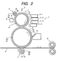
- Electrostatic latent images formed on an electrostatic latent image bearing member (e.g., photosensitive drum) 1 are developed by magnetic brush development or non-magnetic one-component development to form toner images of respective colors on the photosensitive drum 1.
- the toner of the present invention may be mixed with a magnetic carrier so that development can be made using, e.g., a developing means of a two-component development system as shown in Fig. 3. Sspecifically, the development may preferably be carried out while applying an alternating electric field and in such a state that a magnetic brush formed of the toner and the magnetic carrier comes into touch with a photosensitive drum 13.
- a distance B between a developer carrying member (developing sleeve) 11 and the photosensitive drum 13 may preferably be from 100 to 1,000 ⁇ m. This is desirable for preventing carrier adhesion and improving dot reproducibility.
- the developer tends to be insufficiently fed, resulting in a low image density. If it is larger than 1,000 ⁇ m, magnetic lines of force from the magnet S1 may expand to allow the magnetic brush to have a low density, resulting in poor dot reproducibility, or to weaken the force of binding the carrier, tending to cause carrier adhesion.
- the alternating electric field may preferably be applied at a peak-to-peak voltage (Vpp) of from 500 to 5,000 V and a frequency (f) of from 500 to 10,000 Hz, and preferably from 500 to 3,000 Hz, which may each be applied to the process under appropriate selection.
- Vpp peak-to-peak voltage
- f frequency
- the waveform used may be selected from triangular waveform, rectangular waveform, sinusoidal waveform, or waveform with a varied duty ratio. If the peak-to-peak voltage is lower than 500 V, a sufficient image density is difficult to attain, and fogging toner at non-image areas may not be well collected in some cases. If the peak-to-peak voltage is higher than 5,000 V, the electrostatic latent image may be disordered through the magnetic brush to cause a lowering of image quality.
- the frequency (f) is lower than 500 Hz, electric charges may be injected into the carrier, while relating to the process speed, so that carrier adhesion may occur or latent images may be disordered to cause a lowering of image quality. If the frequency (f) is higher than 10,000 Hz, the toner can not follow the electric field to tend to cause a lowering of image quality.
- Vback fog take-off voltage
- the use of a two-component developer having a toner well charged enables a fog take-off voltage (Vback) to be lowered, and enables the photosensitive member to be low charged in its primary charging, thus the photosensitive member can be made to have a longer lifetime.
- the Vback may preferably be 150 V or below, and more preferably 100 V or below, while depending upon the development system.
- a potential of from 200 V to 500 V may preferably be used so that a sufficient image density can be achieved.
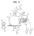
- the magnetic brush on the developing sleeve 11 may preferably be made to come into touch with the photosensitive drum 13 at a width (developing nip C) of from 3 to 8 mm. If the developing nip C is narrower than 3 mm, it may be difficult to realize sufficient image density and dot reproducibility. If it is broader than 8 mm, the developer may be packed into the nip to cause the machine to stop from operating, or it may be difficult to well prevent the carrier adhesion.
- the nip width may appropriately be adjusted by adjusting the distance A between a developer-regulating blade 18 and the developing sleeve 11, or by adjusting the distance B between the developing sleeve 11 and the photosensitive drum 13.
- three or more developing assemblies for magenta, cyan and yellow may be used, and the developer and developing process making use of the toner of the present invention may be used, especially in combination with a development system in which digital latent images are formed.
- the latent images are not affected by the magnetic brush and are not disordered, and hence can be developed faithfully to the dot images.
- the use of the toner of the present invention allows a high transfer efficiency to be achieved, and therefore enables a high image quality in both halftone areas and solid areas to be achieved.
- the use of the toner of the present invention can well bring out the effect of the present invention without any lowering of image quality even in many-sheet copying.
- the toner of the present invention may preferably be used also in development means of a one-component development system.
- An example of an apparatus for developing electrostatic latent images formed on the electrostatic latent image bearing member by the use of a one-component developer is shown below. Examples are not necessarily limited to the following.
- reference numeral 25 denotes an electrostatic latent image bearing member (photosensitive drum). Latent images are formed by electrophotographic processing means or electrostatic recording means.
- Reference numeral 24 denotes a toner carrying member (developing sleeve) formed out of a non-magnetic sleeve made of an aluminum or stainless steel sheet.
- the toner carrying member may preferably have a surface roughness Ra ( ⁇ m) so set as to be not larger than 1.5, preferably not larger than 1.0, and more preferably not larger than 0.5.
- the toner particles transport performance the toner carrying member has can be controlled, the toner layer formed on the toner carrying member can be made thinner and also the times the toner carrying member comes into contact with the toner increases, and hence the charging performance of the toner can also be improved to cooperatively bring about an improvement in image quality.
- the toner carrying member has a surface roughness Ra larger than 1.5, it is difficult that not only the toner layer on the toner carrying member can be made thin, but also the charging performance of the toner may lower, thus no improvement in image quality can be expected.
- the surface roughness Ra of the toner carrying member corresponds to centerline average roughness measured using a surface roughness measuring device (SURFCOADER SE-30H, manufactured by K.K. Kosaka Kenkyusho) according to JIS surface roughness "JIS B-0601").
- a portion of 2.5 mm is drawn out of the roughness curve, setting a measurement length a in the direction of its centerline.
- R a 1 a ⁇ 0 a
- a cylindrical or belt-like member made of, e.g., a non-magnetic metal such as stainless steel or aluminum may preferably be used.
- a metal or resin coat may be provided on the substrate surface, or the substate surface may be coated with a resin in which fine particles of resin, metal, carbon black or charge control agent have been dispersed.
- the speed of surface movement of the toner carrying member may be set 1.05 to 3.0 times the speed of surface movement of the electrostatic latent image bearing member, whereby the toner layer on the toner carrying member can have an appropriate agitation effect and hence the faithful reproduction of the electrostatic latent image can be more improved.
- the speed of surface movement of the toner carrying member is less than 1.05 times the speed of surface movement of the electrostatic latent image bearing member, the agitation effect on the toner layer may become insufficient, so that it may become difficult to form good images. Also, when images requiring a large quantity of toner over a wide area are developed as in the case of solid black images, the quantity of toner fed to the electrostatic latent image tends to become shortm, resulting in an insufficient image density.
- the toner, T is stored in a hopper 21, and fed onto the developing sleeve 24 by means of a feed member 22.
- a feed roller comprised of a porous elastic material as exemplified by a foamed material such as soft polyurethane foam may preferably be used.
- the feed roller may be rotated at a relative speed that is not zero in the fair (or forward) direction or adverse (or backward) direction with respect to the developing sleeve so that the toner can be fed onto the developing sleeve and also the toner remaining on the developing sleeve (the toner not participating in development) can be stripped off.
- the feed roller may be brought into contact with the developing sleeve at a width (a nip) of from 2.0 to 10.0 mm, and more preferably from 4.0 to 6.0 mm.
- a nip width of from 2.0 to 10.0 mm, and more preferably from 4.0 to 6.0 mm.
- this inevitably imposes an excess stress to the toner to tend to cause an increase in agglomeration due to the deterioration of toner, or cause the melt-adhesion or sticking of toner to the developing sleeve and feed roller.
- the toner used in the developing process of the present invention has excellent fluidity and releasability and has a running stability, the toner is preferably usable also in the developing system having such a feed member.
- a brush member made of resin fiber such as nylon or Rayon may also be used as the feed member.
- Such a feed member is very effective in a non-magnetic one-component development carried out using a non-magnetic one-component developer (non-magnetic toner), in which any magnetic binding force can not be utilized. It may also be used in a magnetic one-component development carried out using a magnetic one-component developer (magnetic toner).
- the toner fed onto the developing sleeve is applied in a thin layer and uniformly by a regulation member.
- the regulation member for making thin toner layer is a doctor blade such as a metal blade or magnetic blade provided at a given interval with the developing sleeve.
- a doctor blade such as a metal blade or magnetic blade provided at a given interval with the developing sleeve.
- a rigid-material roller or sleeve made of metal, resin or ceramic may be used, and a magnetism generating means may be provided in the inside thereof.
- An elastic member such as an elastic blade or an elastic roller for applying the toner under pressure contact may be used as the regulation member for making a thin toner layer.
- an elastic blade 23 is, at its upper side base portion, fixed and held on the side of a hopper (developer container) 21 and is so provided that its blade inner face side (or its outer face side in the case of the adverse direction) is, at its lower side, brought into touch with the surface of the developing sleeve 24 under an appropriate elastic pressure in such a state that it is deflected against the elasticity of the blade in the fair direction or adverse direction of the rotation of the developing sleeve.
- a toner layer can be formed which is stable even against environmental variations and is dense.
- the toner tends to be so excessively charged that it tends to melt-adhere to the developing sleeve or elastic blade.
- the toner of the present invention can be preferably used because it has a superior releasability and has a stable triboelectric chargeability.
- the elastic blade it is preferable to select a material of triboelectric series suitable for electrostatically charging the toner to the desired polarity, which includes rubber elastic materials such as silicone rubber, urethane rubber or NBR; synthetic resin elastic materials such as polyethylene terephthalate; and metal elastic materials such as stainless steel, steel and phosphor bronze, as well as composite materials thereof, any of which may be used.
- rubber elastic materials such as silicone rubber, urethane rubber or NBR
- synthetic resin elastic materials such as polyethylene terephthalate
- metal elastic materials such as stainless steel, steel and phosphor bronze, as well as composite materials thereof, any of which may be used.
- resin or rubber may preferably be stuck or applied to, the metal elastic material so as to touch the part coming into contact with the sleeve.
- An organic or inorganic substance may be added to, may be melt-mixed in, or may be dispersed in, the elastic member.
- any of metal oxides, metal powders, ceramics, carbon allotropes, whiskers, inorganic fibers, dyes, pigments and surface-active agents may be added so that the charging performance of the toner can be controlled.
- a fine metal oxide powder such as silica, alumina, titania, tin oxide, zirconium oxide or zinc oxide, carbon black, or a charge control agent commonly used in toners may preferably be incorporated therein.
- a DC electric field and/or an AC electric field may also be applied to a developing blade serving as the regulation member, a feed roller as the feed member and a brush member, whereby the uniform thin-layer coating performance and uniform chargeability can be more improved at the regulated part on the developing sleeve because of the loosening action acting on the toner and the toner can be smoothly fed and stripped off, so that a sufficient image density can be achieved and images with a good quality can be formed.
- the elastic member is effective for the elastic member to be brought into touch with the toner carrying member (developing sleeve) at a pressure of 0.1 kg/m or above, preferably from 0.3 to 25 kg/m, and more preferably from 0.5 to 12 kg/cm, as a linear pressure in the generatrix direction of the toner carrying member.
- a pressure of 0.1 kg/m or above preferably from 0.3 to 25 kg/m, and more preferably from 0.5 to 12 kg/cm, as a linear pressure in the generatrix direction of the toner carrying member.
- the gap ⁇ between the electrostatic latent image bearing member and the toner carrying member may preferably be set to be from 50 to 500 ⁇ m, and the gap between the doctor blade and the toner carrying member may preferably be set to be from 50 to 400 ⁇ m.
- the layer thickness of the toner layer formed on the toner carrying member may preferably be made smaller than the gap ⁇ between the electrostatic latent image bearing member and the toner carrying member.
- the layer thickness of the toner layer may be regulated in such an extent that part of a large number of toner ears constituting the toner layer comes into contact with the surface of the electrostatic latent image bearing member.
- An alternating electric field may be applied across the toner carrying member and the electrostatic latent image bearing member by a bias power source 26. This makes it easy for the toner to move from the toner carrying member to the electrostatic latent image bearing member and to form images with a much higher image quality.
- the alternating electric field may preferably be applied at Vpp of 100 V or above, preferably from 200 to 3,000 V, and more preferably from 300 to 2,000 V. It may also preferably be applied at a frequency (f) of from 500 to 5,000 Hz, more preferably from 1,000 to 3,000 Hz, and still more preferably from 1,500 to 3,000 Hz.
- As the waveform of this electric field rectangular waveform, sine waveform, sawtooth waveform and triangle waveform may be used.
- An asymmetrical AC bias having different time for which regular/reverse voltages are applied may also be used. It is also preferable to use a bias formed by superimposing an AC bias to a DC bias.
- the electrostatic latent image bearing member 1 is a photosensitive drum or photosensitive belt having a photoconductive insulating material layer formed of ⁇ -Se, CdS, ZnO 2 , OPC or a-Si.
- the electrostatic latent image bearing member 1 is rotated driven by means of a drive system (not shown) in the direction of an arrow.
- a photosensitive member having an amorphous silicon photosensitive layer or an organic photosensitive layer may preferably be used.
- the organic photosensitive layer may be of a single-layer type in which the photosensitive layer contains a charge generating material and a charge transporting material in the same layer, or may be a function-separated photosensitive layer comprised of a charge transport layer and a charge generation layer.
- a multi-layer type photosensitive layer comprising a conductive substrate, and the charge generation layer and the charge transport layer superposed thereon in this order is one of preferred examples.
- binder resins for the organic photosensitive layer polycarbonate resins, polyester resins or acrylic resins may preferably be used because they provide a good transfer performance and a good cleaning performance, and may hardly cause faulty cleaning, melt-adhesion of toner to the photosensitive member and filming of external additives.
- the step of charging has a non-contact type charging system making use of a corona charging assembly and being in non-contact with the electrostatic latent image bearing member 1, or a contact type charging system making use of a contact charging member such as a charging roller being in contact with the electrostatic latent image bearing member 1. Either may be used.
- the contact charging system as shown in Fig. 2 may preferably be used so as to enable efficient and uniform charging, simplify the system and make ozone less occur.
- a charging roller 2 is constituted basically of a mandrel 2b at the center and a conductive elastic layer 2a that forms the periphery of the former.
- the charging roller 2 is brought into pressure contact with the surface of the electrostatic latent image bearing member 1 and is rotated following the rotation of the electrostatic latent image bearing member 1.
- the charging process may preferably be performed under conditions of a roller contact pressure of 5 to 500 g/cm, and an AC voltage of 0.5 to 5 kVpp, an AC frequency of 50 Hz to 5 kHz and a DC voltage of ⁇ 0.2 to ⁇ 1.5 kV when a charging bias formed by superimposing an AC voltage on a DC voltage is applied, and a DC voltage of from ⁇ 0.2 to ⁇ 5 kV when only a DC voltage is applied as a charging bias.
- a charging means other than the charging roller there are a method making use of a charging blade and a method making use of a conductive brush. These contact charging means have such effects that high voltage is not required and ozone generation is less.
- the charging roller and charging blade as contact charging means may preferably be made of a conductive rubber, and a release coat may be provided on its surface.
- the release coat may be formed out of a nylon resin, PVDF (polyvinylidene fluoride) or PVDC (polyvinylidene chloride), any of which may be used.
- the toner image on the electrostatic latent image bearing member is primarily transferred to an intermediate transfer member 5 to which a voltage (e.g., ⁇ 0.1 to ⁇ 5 kV) is applied.
- a voltage e.g., ⁇ 0.1 to ⁇ 5 kV
- the surface of the electrostatic latent image bearing member is cleaned by a cleaning means 9 having a cleaning blade 8.
- the intermediate transfer member 5 is comprised of a pipe-like conductive mandrel 5b and a medium-resistance elastic material layer 5a formed on its periphery.
- the mandrel 5b may comprise a plastic pipe provided thereon with a conductive coating.
- the medium-resistance elastic material layer 5a is a solid or foamed-material layer made of an elastic material such as silicone rubber, Teflon rubber, chloroprene rubber, urethane rubber or EPDM (an ethylene-propylene-diene terpolymer) in which a conductivity-providing agent such as carbon black, zinc oxide, tin oxide or silicon carbide has been mixed and dispersed to adjust electrical resistance (volume resistivity) to a medium resistance of from 10 5 to 10 11 . ⁇ cm.
- an elastic material such as silicone rubber, Teflon rubber, chloroprene rubber, urethane rubber or EPDM (an ethylene-propylene-diene terpolymer) in which a conductivity-providing agent such as carbon black, zinc oxide, tin oxide or silicon carbide has been mixed and dispersed to adjust electrical resistance (volume resistivity) to a medium resistance of from 10 5 to 10 11 . ⁇ cm.
- the intermediate transfer member 5 is provided in contact with the bottom part of the electrostatic latent image bearing member, being axially supported in parallel with the electrostatic latent image bearing member 1, and is rotated at the same peripheral speed as the electrostatic latent image bearing member 1 in the anti-clockwise direction as shown by an arrow.
- the first-color toner image formed and held on the surface of the electrostatic latent image bearing member 1 is, while passing through the transfer nip portion where the electrostatic latent image bearing member 1 and the intermediate transfer member 5 come into contact, intermediately sequencially transferred to the periphery of the intermediate transfer member 5 by the aid of the electric filed formed at the transfer nip portion by a transfer bias applied to the intermediate transfer member 5.
- the surface of the intermediate transfer member 5 may be cleaned by a detachable cleaning means 10.
- the cleaning means 10 is detached from the surface of the intermediate transfer member so that the toner image is not disturbed.
- a transfer means 7 is provided in contact with the bottom part of the intermediate transfer member 5, being axially supported in parallel with the intermediate transfer member 5.
- the transfer means 7 is, e.g., a transfer roller or a transfer belt, and is rotated at the same peripheral speed as the intermediate transfer member 5 in the clockwise direction as shown by an arrow.
- the transfer means 7 may be so provided that it comes into direct contact with the intermediate transfer member 5, or may be so disposed that a belt is brought into contact between the intermediate transfer member 5 and the transfer means 7.
- the transfer roller it is basically comprised of a mandrel 7b at the center and a conductive elastic layer 7a that forms the periphery of the former.
- the intermediate transfer member and the transfer roller may be of made commonly available materials.
- the elastic layer of the transfer roller may be made to have a volume resistivity set smaller than the volume resistivity of the elastic layer of the intermediate transfer member, whereby the voltage applied to the transfer roller can be lessened, good toner images can be formed on the recording medium and also the recording medium can be prevented from being wound around the intermediate transfer member.
- the elastic layer of the intermediate transfer member may preferably have a volume resistivity at least 10 times the volume resistivity of the elastic layer of the transfer roller.
- a conductive elastic layer 7b of the transfer roller 7 is made of, e.g., an elastic material having a volume resistivity of 10 6 to 10 10 ⁇ cm, such as polyurethane, or an ethylene-propylene-diene type terpolymer (EPDM), with a conductive material such as carbon dispersed therein.
- a bias is applied to the mandrel 7a by a constant voltage power source. As bias conditions, a voltage of from ⁇ 0.2 to ⁇ 10 kV is preferred.
- the toner image on the recording medium 6 is fixed by means of a heat-and-pressure fixing means.
- the heat-and-pressure fixing means may include a heat roll system constituted basically of a heat roller internally provided with a heating element such as a halogen heater and an elastic-material pressure roller brought into contact therewith under pressure, and a system in which the toner image is fixed by heat and pressure by means of a heater through a film (Figs. 6 and 7).
- the toner of the present invention can well match the above heat-and-pressure fixing means because of its superior fixing performance and anti-offset properties.
- the toner of the present invention With the toner of the present invention, a transfer efficiency at the transfer step is high, the toner remaining after transfer is small and cleaning performance is superior, and hence the filming may hardly occur on the electrostatic latent image bearing member. Moreover, with the toner of the present invention, the external additive is less embedded in the toner particle surfaces, and hence a good image quality can be maintained over a long period of time. Accordingly, it can be used preferably in an image forming apparatus shown in Fig. 5, having what is called the reuse mechanism in which the toner remaining on the electrostatic latent image bearing member and intermediate transfer member after transfer is removed by a cleaning means such as a cleaning blade, collected and reused.
- reference numeral 40 denotes a photosensitive drum serving as an electrostatic latent image bearing member; 49, a transfer roller as a transfer member with which the toner images formed on the surface of the photosensitive drum 40 are transferred to a recording medium 50; and 41, a cleaner with which the toner remaining on the surface of the photosensitive drum 40 after transfer is scraped off and collected with an elastic blade 42 serving as a cleaning blade.
- Reference numeral 43 denotes a cleaner screw with which the toner collected in the cleaner 41 is transported inside the cleaner 41; and 44, a feed pipe internally provided with a transport screw and through which the toner transported with the cleaner screw 43 is transported to a toner hopper 45.
- Reference numeral 46 denotes a developing assembly; and 48, a developing sleeve as a developer carrying member for carrying and transporting thereon the developer held in the developing assembly.
- Reference numeral 47 denotes a charging roller for primarily charging the photosensitive drum 40.
- the photosensitive drum 40 is primarily electrostatically charged with the primary charging roller 47, and an electrostatic latent image is formed by an exposure means (not shown). Thereafter, this electrostatic latent image is developed by the use of the developer having the toner and carried on the developing sleeve 48 of the developing assembly 46, to form a toner image.
- the toner image formed on the photosensitive drum 40 is transferred to the recording medium 50 by means of the transfer roller 49, and the toner image transferred to the recording medium 50 is fixed by heat and pressure to the recording medium 50 by means of a heat roller fixing assembly 51 serving as a heat-fixing device.
- the transfer residual toner present on the surface of the photosensitive drum 40 after transfer is scraped off with the elastic blade 42, and is once collected in the cleaner 41, which is thereafter sent inside the cleaner 41, further transported with the cleaner screw 43, passes through the feed pipe 44 provided with a transport screw, and, through the hopper 45, returned to the developing assembly 46, where the toner is again used for the development of electrostatic latent images.
- the image forming apparatus shown in Fig. 5 reuses the toner as described above.
- the toner of the present invention has an excellent running performance because of the specific polycarbonate resin contained in it, and hence can also be applied in an image forming method employing a contact development system which requires a high running performance of toner.
- a monochromatic image forming method will be described with reference to Fig. 8 where the contact development system is used and also a cleanerless process is used.
- reference numeral 100 denotes a developing assembly; 109, a photosensitive member; 105, a recording medium such as paper; 106, a transfer member; 107, a fixing pressure roller; 108, a fixing heat roller; and 110, a primary charging member which directly charges the photosensitive member 109 in contact with it.
- a bias power source 115 is connected to the primary charging member 110 so that the surface of the photosensitive member 109 is uniformly charged.
- the developing assembly 100 holds a toner 104, and has a toner carrying member 102 which is rotated in the direction of an arrow in contact with the photosensitive member 109. It also has a developing blade 101 for regulating toner quantity and charging the toner, and a coating roller 103 which is rotated in the direction of an arrow in order to cause the toner 104 to adhere to the toner carrying member 102 and also charge the toner by friction with the toner carrying member 102. To the toner carrying member 102, a development bias power source 117 is connected to the toner carrying member 102.
- a bias power source 118 is also connected to the coating roller 103, where a voltage is set on the negative side with respect to the development bias when a negatively chargeable toner is used and on the positive side with respect to the development bias when a positively chargeable toner is used.
- a power source 116 for transfer bias with a polarity reverse to that of the photosensitive member 109 is connected to the transfer member 106.
- the length of rotational direction, what is called development nip width, at the contact area between the photosensitive member 109 and the toner carrying member 102 may preferably be 0.2 mm or larger and 8.0 mm or smaller. If it is smaller than 0.2 mm, the amount of development may be too insufficient to attain a satisfactory image density and also the transfer residual toner may not be well collected. If it is larger than 8.0 mm, the toner may be fed in an excessively large quantity to tend to cause fog and also to adversely affect the wear of the photosensitive member.
- an elastic roller having an elastic layer on its surface may preferably be used.
- materials for the elastic layer used those having a hardness of from 20 to 65 degrees (JIS A) may preferably be used.
- the toner carrying member may preferably have a resistance within the range of approximately from 10 2 to 10 9 ⁇ cm as volume resistivity. If it has a volume resistivity lower than 10 2 ⁇ cm, there is a possibility that excess electric current flows when, e.g., the photosensitive member 109 has pinholes on its surface. If on the other hand it has a volume resistivity higher than 10 9 ⁇ cm, the toner is liable to cause charge-up due to triboelectric charging, tending to cause a decrease in image density.
- the toner may preferably be applied on the toner carrying member in a quantity of from 0.1 mg/cm 2 to 1.5 mg/cm 2 . If applied in a quantity less than 0.1 mg/cm 2 , it is difficult to obtain a sufficient image density, and, in a quantity larger than 1.5 mg/cm 2 , it is difficult to uniformly triboelectrically charge all the individual toner particles, causing poor restraint of fog. It may more preferably be applied in a quantity of from 0.2 mg/cm 2 to 0.9 mg/cm 2 .
- the toner coat quantity is controlled by the developing blade 101.
- This developing blade 101 comes into contact with the toner carrying member 102 through the toner layer at a contact pressure of from 5 g/cm to 50 g/cm as a preferable range. If the contact pressure is lower than 5 g/cm, it may be difficult not only to control the toner coat quantity but also to effect uniform triboelectric charging, causing fog to occur. If the contact pressure is higher than 50 g/cm, the toner particles may undergo an excess load to tend to cause deformation of particles or the melt-adhesion of toner to the developing blade or toner carrying member.
- a metal blade or roller may also be used besides the elastic blade for applying the toner in pressure contact.
- the elastic regulation member it is preferable to select a material of triboelectric series suitable for electrostatically charging the toner to the desired polarity, which includes rubber elastic materials such as silicone rubber, urethane rubber or NBR; synthetic resin elastic materials such as polyethylene terephthalate; and metal elastic materials such as stainless steel, steel and phosphor bronze, as well as composite materials thereof, any of which may be used.
- rubber elastic materials such as silicone rubber, urethane rubber or NBR
- synthetic resin elastic materials such as polyethylene terephthalate
- metal elastic materials such as stainless steel, steel and phosphor bronze, as well as composite materials thereof, any of which may be used.
- resin or rubber may preferably be stuck or applied to the metal elastic material so as to touch the part coming into contact with the sleeve.
- An organic or inorganic substance may be added to, may be melt-mixed in, or may be dispersed in, the elastic regulation member.
- any of metal oxides, metal powders, ceramics, carbon allotropes, whiskers, inorganic fibers, dyes, pigments and surface-active agents may be added so that the charging performance of the toner can be controlled.
- a fine metal oxide powder such as silica, alumina, titania, tin oxide, zirconium oxide or zinc oxide, carbon black, or a charge control agent commonly used in toners may preferably be incorporated therein.
- a DC electric field and/or an AC electric field may also be applied to the regulation member, whereby the uniform thin-layer coating performance and uniform chargeability can be more improved because of the loosening action acting on the toner, so that a sufficient image density can be achieved and images with a good quality can be formed.
- the primary charging member 110 uniformly electrostatically charges the photosensitive member 109 rotating in the direction of an arrow.
- the primary charging member 110 used here is a charging roller constituted basically of a mandrel 110b at the center and a conductive elastic layer 110a that forms the periphery of the former.
- the charging roller 110 is brought into pressure contact with the surface of the photosensitive member 109 and is rotated followingly as the photosensitive member 109 is rotated.
- the charging process may preferably be performed under the conditions of a roller contact pressure of 5 to 500 g/cm.
- a charging bias formed of DC voltage alone or a charging bias formed by superimposing an AC voltage on a DC voltage may be used as an applied voltage.
- the charging bias formed of DC voltage alone may preferably be used. In such an instance, the voltage may be applied at a value of from ⁇ 0.2 to ⁇ 5 kV.
- the charging roller and charging blade as contact charging means may preferably be made of a conductive rubber, and a release coat may be provided on its surface.
- the release coat may be formed out of a nylon resin, PVDF (polyvinylidene fluoride) or PVDC (polyvinylidene chloride), any of which may be used.
- an electrostatic latent image corresponding to information signals is formed on the electrostatic latent image bearing member 109 by exposure 111 from a light-emitting device, and the electrostatic latent image is developed into a visible image by the use of the toner at the region coming into contact with the toner carrying member 102.
- a development system of forming a digital latent image on the photosensitive member may be used in combination. This enables development faithful to a dot latent image because the latent image is not disordered.
- the visible image is transferred to the recording medium 105 by means of the transfer member 106.
- the transferred toner image 112 is, together with the recording medium 105, further passed between the heat roller 108 and the pressure roller 107, and is fixed there, obtaining a permanent image.
- a heat roll system constituted basically of a heat roller internally provided with a heating element such as a halogen heater and an elastic-material pressure roller brought into contact therewith under pressure, may be used, and in addition, a system in which the toner image is fixed by heat and pressure by means of a heater through a film may also be used.
- a transfer part in the transfer step and a charging part in the carging step are arranged in the named order in the moving direction of the photosensitive member 109 as an electrostatic latent image bearing member, and no cleaning member coming into contact with the surface of said electrostatic latyent image bearing member to remove the toner remaining on the surface after transfer is present between the transfer part and charging part and between the charging part and developing part.
- the transfer residual toner 113 not transferred and remaining on the photosensitive member 109 is passed between the photosensitive member 109 and the primary charging member 110, and again reaches the development nip portion, where it is collected in the developing assembly 100 by means of the toner carrying member 102.
- development may be effected by a developing means having, e.g., a developing apparatus 131 as shown in Fig. 9.
- a developing means having, e.g., a developing apparatus 131 as shown in Fig. 9.
- the development is made in such a state that a toner 134 used as a one-component developer, fed through a coating roller 132 and whose coat layer is regulated with a developing blade 133 comes into contact with a photosensitive member 135 while a DC or alternating electric field is applied to a developer carrying member 137 from a power source 136.
- the alternating electric field any of triangular waveform, rectangular waveform, sinusoidal waveform, waveform with a varied duty ratio and periodic alternating waveform may be used under appropriate selection.
- a DC electric filed is preferably used because the load of voltage on the photosensitive member is less, and the applied voltage is set at a suitable value between the dark potential (potential immediately after charging) and the light potential (potential after charging) on the photosensitive member.
- the toner carrying member may be rotated in the same direction as the rotation of the photosensitive member or may be rotated in the reverse direction.
- its peripheral speed may preferably be set from 1.05 to 3.0 times the peripheral speed of the photosensitive member.
- the peripheral speed is less than 1.05 times the peripheral speed of the photosensitive member, the agitation effect the toner layer undergoes may become insufficient to make it difficult to achieve a good image quality and also, when images requiring the toner in a large quantity over a wide area as in the case of solid black images are developed, the quantity of the toner fed to electrostatic latent images may become insufficient, tending to cause a decrease in image density.
- the effect obtainable by utilizing the difference in peripheral speed to physically take the photosensitive member surface off the part to which the toner has adhered and by utilizing an electric field to collect the toner can be expected when the transfer residual toner is present on the photosensitive member in close adhesion. Accordingly, the higher the peripheral speed ratio is, the more advantageous it is for the transfer residual toner to be collected. However, if on the other hand the peripheral speed ratio is greater than 3.0, not only the various problems caused by excessive charging of toner as stated previously but also the deterioration of toner due to mechanical stress and the adhesion of toner to the toner carrying member may occur accelaratingly.
- a photosensitive drum or photosensitive belt having a photoconductive insulating material layer formed of ⁇ -Se, CdS, ZnO 2 , OPC or a-Si may preferably be used.
- binder resins for the organic photosensitive layer in the OPC photosensitive member polycarbonate resins, polyester resins and acrylic resins may preferably be used because they provide a good transfer performance and a good cleaning performance, and may hardly cause faulty cleaning, melt-adhesion of toner to the photosensitive member and filming of external additives.
- the toner image on the photosensitive member (electrostatic latent image bearing member) 135 is primarily transferred to the intermediate transfer member as described previously, and subsequently the image is formed in such a manner as described with reference to Fig. 2.
- the toner layer on the toner carrying member comes into contact with the photosensitive member surface and it is preferable to use a reverse development system.
- its use in combination with the cleanerless process in which the cleaning means such as a cleaning blade is not additionally provided and the developing assembly itself collects the transfer residual toner remaining on the photosensitive member can greatly miniaturize the apparatus.
- a bias having a DC or AC component is applied so that the potential is controlled to enable development and collection of the toner remaining on the photosensitive member.
- the DC component is positioned between the light-area potential and the dark-area potential.
- an elastic roller may be used and a method may be used in which the toner is applied on the elastic roller surface and the coated toner is brought into contact with the photosensitive member surface.
- the electric field acting between the photosensitive member and the elastic roller facing the photosensitive member surface through the toner is utilized to remove the transfer residual toner by cleaning in the developing step.
- the elastic roller surface or the vicinity thereof it is necessary for the elastic roller surface or the vicinity thereof to have a potential so that an electric field is formed at a narrow gap between the photosensitive member surface and the toner carrying member surface.
- a method may also be used in which the elastic rubber of the elastic roller is controlled to have a resistance in the medium-resistance region to keep the electric field while preventing its conduction to the photosensitive member surface, or a thin-layer insulating layer is provided on the surface layer of a conductive layer.
- a conductive resin sleeve comprising a conductive roller coated thereon with an insulating substance on its side facing the photosensitive member surface, or an insulating sleeve provided with a conductive layer on its side not facing the photosensitive member.
- a rigid-material roller as the toner carrying member and use a flexible member such as a belt as the photosensitive member.
- the developing roller as the toner carrying member may preferably have a volume resistivity in the range of from 10 2 to 10 9 ⁇ cm.
- the toner remaining after cleaning may adhere to the charging member in the post-step contact charging to cause faulty charging, if usual toners are used. Accordingly, the quantity of the transfer residual toner must be made smaller than that in the corona discharging or the like where the charging means does not come into contact with the photosensitive member.
- the toner whose SF-1, SF-2 and (SF-2)/(SF-1) have been strictly defined in the ranges previously described.
- the toner according to the present invention because of the controlling of the surface shape of toner particles, is so high in transfer efficiency in the transfer step as to leave less transfer residue, and hence has a superior cleaning performance at the time of cleaning-at-development in the developing assembly.
- it since it contains the tough polycarbonate resin, it may hardly cause the filming on the contact charging member, photosensitive drum and intermediate transfer member.
- the external additives are less embedded in the toner particle surfaces than conventional toners are used, and hence a good image quality can be maintained over a long period of time.
- the toner having a good running performance and a good transfer efficiency can be obtained by specifying the binder components in the toner composition. Moreover, the toner can be transferred at a high transfer efficiency without causing the melt-adhesion of toner particles to the contact charging member, photosensitive drum and intermediate transfer member, and can also preferably match image forming apparatus.
- the resin (1) was analyzed to reveal that, in its molecular weight distribution as measured by GPC, it had a low-molecular-weight side peak molecular weight of 10,000, a high-molecular-weight side peak molecular weight of 750,000, a weight-average molecular weight (Mw) of 360,000, a number-average molecular weight (Mn) of 6,000 and a Mw/Mn ratio of 60, and also had a glass transition temperature (Tg) of 60°C.
- the resin (2) was analyzed to reveal that, in its molecular weight distribution as measured by GPC, it had a peak molecular weight of 40,000, a weight-average molecular weight (Mw) of 42,000, a number-average molecular weight (Mn) of 12,000 and a Mw/Mn ratio of 3.5, and also had a glass transition temperature (Tg) of 60°C.
- Example 1 (by weight) Resin (1) 100 parts 1,1-Bis(4-hydroxyphenyl)cyclohexane polycarbonate (peak molecular weight: 5,000; Mw: 6,000; Mn: 1,700) 10 parts Carbon black (BET specific surface area: 85 m 2 /g) 10 parts Negative charge control agent (a salicylic acid iron complex) 2 parts Low-molecular-weight polyethylene with a maximum endothermic peak at 107°C 5 parts
- the above materials were uniformly dispersed and mixed, and thereafter the mixture obtained was melt-kneaded.
- the kneaded product obtained was finely pulverized, and the resultant particles were further treated to make surface modification to make them smooth and spherical.
- toner particles (1) 100 parts by weight of the toner particles (1) and 2 parts by weight of a hydrophobic fine silica powder (BET specific surface area: 200 m 2 /g) were dry-process mixed by means of a Henschel mixer to obtain toner (1). Then, 6 parts by weight of the toner (1) thus obtained and 94 parts by weight of a resin-coated magnetic ferrite carrier (average particle diameter: 50 ⁇ m) were blended to produce two-component developer (1) for magnetic brush development.
- BET specific surface area 200 m 2 /g
- the toner particles (1) had, as shown in Table 1, the value of SF-1 of 135, the value of SF-2 of 118, the value of (SF-2)/(SF-1) of 0.87, a weight-average particle diameter of 7.3 ⁇ m, a high-molecular-weight side peak molecular weight of 650,000 and a low-molecular-weight side peak molecular weight of 10,000.
- toner (1) components having molecular weight of 1,000 or less, in its molecular weight distribution as measured by GPC of THF-soluble matter, were separated and collected by GPC and they were analyzed by 1 H-NMR, 13 C-NMR and IR. As a result, as shown in Table 1, a component having in its structure a repeating unit of the polycarbonate resin, contained in the components having molecular weight of 1,000 or less, was contained in an amount of 1.0% by weight based on the weight of the toner.
- the 1,1-bis(4-hydroxyphenyl)cyclohexane polycarbonate used in the production of the toner particles (1) is purified by repeating its reprecipitation using methylene chloride and isopropanol to reduce lower molecular weight components and impurities.
- Toner particles (2), toner (2) and developer (2) were produced in the same manner as in Example 1 except that as the polycarbonate resin the 1,1-bis(4-hydroxyphenyl)cyclohexane polycarbonate was replaced with 1-phenyl-1,1-bis(4-hydroxyphenyl)ethane polycarbonate (peak molecular weight: 4,500; Mw: 5,000; Mn: 1,500). Analysis and evaluation on the toner particles (2) and toner (2) were made similarly to obtain the results as shown in Table 1.
- the 1-phenyl-1,1-bis(4-hydroxyphenyl)ethane polycarbonate used in the production of the toner particles (2) is purified by repeating its reprecipitation using methylene chloride and isopropanol to reduce lower molecular weight components and impurities.
- Toner particles (3), toner (3) and developer (3) were produced in the same manner as in Example 1 except that as the polycarbonate resin the 1,1-bis(4-hydroxyphenyl)cyclohexane polycarbonate was replaced with 2,2-bis(3-methyl-4-hydroxyphenyl)propane polycarbonate (peak molecular weight: 4,000; Mw: 4,500; Mn: 1,200). Analysis and evaluation on the toner particles (3) and toner (3) were made similarly to obtain the results as shown in Table 1.
- the 2,2-bis(3-methyl-4-hydroxyphenyl)propane polycarbonate used in the production of the toner particles (3) is purified by repeating its reprecipitation using methylene chloride and isopropanol to reduce lower molecular weight components and impurities.
- Toner particles (4) and (5), toners (4) and (5) and developers (4) and (5) were produced in the same manner as in Example 1 except that conditions for the surface modification treatment were changed. Analysis and evaluation on the toner particles (4) and (5) and toners (4) and (5) were made similarly to obtain the results as shown in Table 1.
- Toner particles (6), toner (6) and developer (6) were produced in the same manner as in Example 1 except that the surface modification treatment was not made. Analysis and evaluation on the toner particles (6) and toner (6) were made similarly to obtain the results as shown in Table 1.
- Toner particles (7), toner (7) and developer (7) were produced in the same manner as in Example 1 except that the resin (1) was replaced with the resin (2). Analysis and evaluation on the toner particles (7) and toner (7) were made similarly to obtain the results as shown in Table 1.
- Toner particles (8), toner (8) and developer (8) were produced in the same manner as in Example 1 except that the salicylic acid iron complex was replaced with a compound formed of a monoazo dye and iron. Analysis and evaluation on the toner particles (8) and toner (8) were made similarly to obtain the results as shown in Table 1.
- Toner particles (9) for comparison, toner (9) for comparison and developer (9) for comparison were produced in the same manner as in Example 1 except that the polycarbonate resin was not used. Analysis and evaluation on the toner particles (9) for comparison and toner (9) for comparison were made similarly to obtain the results as shown in Table 1.
- Toner particles (10) for comparison, toner (10) for comparison and developer (10) for comparison were produced in the same manner as in Example 1 except that 25 parts by weight of a compound formed by ester linkage of p-tert-butyl phenol and 1,1-bis(4-hydroxyphenyl)cyclohexane through carbon was further added. Analysis and evaluation on the toner particles (10) for comparison and toner (10) for comparison were made similarly to obtain the results as shown in Table 1.
- Bisphenol A/biphenol/diethylene glycol copolymer polycarbonate peak molecular weight: 12,000; Mw: 13,000; Mn: 4,000; Tg: 50°C) 100 parts Carbon black (BET specific surface area: 85 m 2 /g) 10 parts Negative charge control agent (a salicylic acid iron complex) 2 parts Low-molecular-weight polyethylene with a maximum endothermic peak at 107°C 5 parts
- Example 1 The above materials were uniformly mixed, and thereafter the mixture obtained was melt-kneaded, followed by fine pulverization. Then, the subsequent procedure of Example 1 was repeated to obtain toner particles (11) for comparison, toner (11) for comparison and developer (11) for comparison. Analysis and evaluation on the toner particles (11) for comparison and toner (11) for comparison were made similarly to obtain the results as shown in Table 1.
- the bisphenol A/biphenol/diethylene glycol copolymer polycarbonate used in the production of the toner particles (11) is not subjected to purification by reprecipitation.
- Comparative Example 4 (by weight) Resin (1) 50 parts 1,1-Bis(4-hydroxyphenyl)cyclohexane polycarbonate (peak molecular weight: 3,000; Mw: 3,500; Mn: 1,000) 50 parts Carbon black (BET specific surface area: 85 m 2 /g) 10 parts Negative charge control agent (a salicylic acid iron complex) 2 parts Low-molecular-weight polyethylene with a maximum endothermic peak at 107°C 5 parts
- the above materials were uniformly dispersed and mixed, and thereafter the mixture obtained was melt-kneaded.
- the kneaded product obtained was finely pulverized, and the resultant particles were further treated to make surface modification to make them smooth and spherical.
- toner particles (12) for comparison 100 parts by weight of the toner particles (12) for comparison and 2 parts by weight of a hydrophobic fine silica powder (BET specific surface area: 200 m 2 /g) were dry-process mixed by means of a Henschel mixer to obtain toner (12) for comparison. Then, 6 parts by weight of the toner (12) for comparison thus obtained and 94 parts by weight of a resin-coated magnetic ferrite carrier (average particle diameter: 50 ⁇ m) were blended to produce two-component developer (12) for comparison.
- BET specific surface area 200 m 2 /g
- FIG. 2 schematically illustrates a cross section of an image forming apparatus used in the present Examples.
- Fig. 3 illustrates a developing system of the image forming apparatus.
- the photosensitive drum 1 comprises a substrate 1a and provided thereon a photosensitive layer 1b having an organic photo-semiconductor, and is rotated in the direction of an arrow.
- the charging roller 2 the conductive elastic layer 2a and the mandrel 2b facing the photosensitive drum and rotating in contact with it
- the surface of the photosensitive drum 1 is electrostatically charged to have a surface potential of about -600 V.
- Exposure 3 is carried out using a polygon mirror by on-off control on the photosensitive drum 1 in accordance with digital image information, whereby an electrostatic latent image with an exposed-area potential of -100 V and a dark-area potential of -600 V is formed.
- the black toner was imparted to the surface of the photosensitive drum 1 to form toner images by reverse development.
- the toner images are transferred to the intermediate transfer member 5.
- the toner remaining on the photosensitive drum 1 after transfer is collected in a residual toner container 9 by means of a cleaning member 8.
- the intermediate transfer member 5 is comprised of the pipe-like mandrel 5b and the elastic layer 5a provided thereon by coating, formed of nitrile-butadiene rubber (NBR) in which a conductivity-providing agent of carbon black has been well dispersed.
- NBR nitrile-butadiene rubber
- the coat layer 5a thus formed has a hardness according to JIS K-6301, of 30 degrees and a volume resistivity of 10 9 ⁇ cm.
- Transfer electric current necessary for the transfer from the photosensitive drum 1 to the intermediate transfer member 5 is about 5 ⁇ A, which can be obtained by applying a voltage of +500 V to the mandrel 5b from a power source.
- the transfer roller 7 has an external diameter of 20 mm.
- the transfer roller 7 has an elastic layer 7a formed by coating on a mandrel 7b of 10 mm diameter, a foamable material of an ethylene-propylene-diene terpolymer (EPDM) in which carbon, a conductivity-providing agent has been well dispersed.
- EPDM ethylene-propylene-diene terpolymer
- As the elastic layer 7a the one showing a volume resistivity of 10 6 ⁇ •cm and a hardness according to JIS K-6301, of 35 degrees was used. A voltage was applied to the transfer roller to flow a transfer current of 15 ⁇ A.
- the heat fixing assembly H a fixing assembly of a hot-roll type having no function of oil application was used.
- both the upper roller and the lower roller those having surface layers of fluorine resin were used, having roller diameter of 50 mm.
- the fixing temperature was set at 180°C, and the nip width at 7 mm.
- a 100-sheet printing test was made in an environment of normal temperature and normal humidity (N/N: 25°C, 60%RH) at a printing rate of 8 sheets(A4-size)/minute in a monochromatic continuous mode (i.e., a mode in which the consumption of the toner was accelerated without a pause of the developing assembly) while successively supplying each of the developers (1) to (8) and the developers (9) to (12) for comparison.
- a 5,000-sheet image printing test was made in the same printing mode. Then, evaluation on printed images thus obtained was made in respect of the items shown later.
- Example 2 Evaluation was made in the same manner as in Example 1 except that the developing assembly of the image forming apparatus, shown in Fig. 3, was replaced with the one shown in Fig. 4, the movement speed of the toner carrying member surface was so set as to be 3.0 times the movement speed of the electrostatic latent image bearing member surface, and the printing test was made in a monochromatic intermittent mode (i.e., a mode in which the developing assembly was made to pause for 10 seconds every time the images were printed on one sheet and the deterioration of the toner was accelerated by preliminary operation of the developing assembly when again driven) while successively supplying each of the toner (1) produced in Example 1 and the toner (9) for comparison produced in Comparative Example 1.
- a monochromatic intermittent mode i.e., a mode in which the developing assembly was made to pause for 10 seconds every time the images were printed on one sheet and the deterioration of the toner was accelerated by preliminary operation of the developing assembly when again driven
- the toner carrying member used here had a surface roughness Ra of 1.5, and the toner regulation blade used was the one comprising a phosphor bronze base plate to which urethane rubber was bonded and the side coming into contact with the toner carrying member of which was coated with nylon.
- Table 4 Printed-Image Evaluation Results Toner N/N image density L/L image density Change in image density Fog Blank areas
- Example: 9 A A A A A A Comparative Example: 5 (9) D D C C C
- Table 5 Evaluation Results of Matching to Image Forming Apparatus Toner Developing sleeve Photosensitive drum Intermediate transfer member Fixing assembly
- Example: 9 A A A A Comparative Example: 5 (9) D D D D D
- a reuse mechanism was attached to a commercially available laser beam printer LBP-EX (manufactured by CANON INC.) to remodel the printer, which was again set up and used. More specifically, as shown in Fig. 5, a system was attached in which the transfer residual toner present on the surface of the photosensitive drum 40 was scraped off with the elastic blade 42 of the cleaner 41, coming into touch with the photosensitive drum, which was thereafter sent inside the cleaner by means of a cleaner roller, further passed through the cleaner screw 43, passed through the feed pipe 44 provided with a transport screw, and, through the hopper 45, returned to the developing assembly 46, where the collected toner was again used.
- LBP-EX laser beam printer
- the primary charging roller 47 used was a rubber roller (diameter: 12 mm; contact pressure: 50 g/cm) in which conductive carbon was dispersed, and covered with a nylon resin.
- a dark-area potential V D of -700 V and a light-area potential V L of -200 V were formed by laser exposure (600 dpi).
- a developing sleeve 48 whose surface was coated with a resin having carbon black dispersed therein and had a surface roughness Ra of 1.1 was used, where its surface movement speed was so set as to be 1.1 times the movement speed of the photosensitive drum surface, and then the gap (S-D distance) between the photosensitive drum and the developing sleeve was set at 270 ⁇ m.
- a blade made of urethane rubber was used in contact with the developing sleeve.
- the development bias a bias formed by superimposing an AC bias component on a DC bias component was used.
- a fixing assembly shown in Figs. 6 and 7 was used as the heat fixing assembly H.
- the surface temperature of a temperature detector 31d of a heating element 31 was set at 170°C
- the total pressure between the heating element 31 and a spongy pressure roller 33 having a foam of silicon rubber in its lower layer was set to be 8 kg
- the nip between the pressure roller and a fixing film 32 was set to be 6 mm.
- As the fixing film 32 a 60 ⁇ m thick heat-resistant polyimide film was used which had on its side coming into contact with the recording medium a low-resistance release layer formed of PTEF (of a high-molecular-weight type) having a conductive material dispersed therein.
- PTEF of a high-molecular-weight type
- Table 6 Printed-Image Evaluation Results Toner N/N image density L/L image density Change in image density Fog Blank areas
- Example: 10 A A A A A A Comparative Example: 6 (10) D D D D C
- Table 7 Evaluation Results of Matching to Image Forming Apparatus Toner Developing sleeve Photosensitive drum Fixing assembly
- Example: 10 A A A Comparative Example: 6 (10) D D D D
- a printing test was made in the same manner as in Example 10 except that the toner reuse mechanism of Fig. 5 was detached and images were printed in a continuous mode (i.e., a mode in which the consumption of the toner was accelerated without a pause of the developing assembly) while supplying the toner (2) produced in Example 2.
- a continuous mode i.e., a mode in which the consumption of the toner was accelerated without a pause of the developing assembly
- Image density of images printed on the 100th sheet was evaluated.
- the image density was measured with MACBETH REFLECTION DENSITOMETER (manufactured by Macbeth Co.), as relative density with respect to an image printed on a white ground area with a density of 0.00 of an original.
- the image density of images printed on the 100th sheet and 5,000th sheet in the environment of low temperature and low humidity was measured, and any change in image density was calculated according to the following expression.
- Fog density (%) was calculated from a difference between the whiteness at a white background area of images printed on the 100th sheet in the environment of normal temperature and normal humidity and the whiteness of the recording medium to make evaluation on image fog.
- the fog density was measured with REFLECTOMETER (manufactured by Tokyo Denshoku Co., Ltd.).
- the above materials were mixed using a blender, and the mixture obtained was melt-kneaded by means of a twin-screw extruder heated to 130°C.
- the toner particles (13) had the value of SF-1 of 145, the value of SF-2 of 130, the value of (SF-2)/(SF-1) of 0.90, a weigh-average particle diameter of 6.9 ⁇ m, a high-molecular-weight side peak molecular weight of 700,000 and a low-molecular-weight side peak molecular weight of 10,000.
- Toner particles (14), toner (14) and developer (14) were produced in the same manner as in Example 12 except that as the polycarbonate resin the 1,1-bis(4-hydroxyphenyl)cyclohexane polycarbonate was replaced with 20 parts by weight of a bisphenol A/biphenol/hexamethylene glycol copolymer polycarbonate (peak molecular weight: 30,000; Mw: 32,000; Mn: 10,000; Tg: 60°C).
- the bisphenol A/biphenol/hexamethylene glycol copolymer polycarbonate used in the production of toner (14) is purified by repeating its reprecipitation using dichloromethane and isopropanol to reduce lower molecular weight components and impurities.
- Example 14 (by weight) Resin (1) 100 parts Carbon black (BET specific surface area: 104 m 2 /g) 10 parts Negative charge control agent (a salicylic acid iron complex) 2 parts Low-molecular-weight polyethylene with a maximum endothermic peak at 107°C 5 parts The above materials were mixed using a blender, and the mixture obtained was melt-kneaded by means of a twin-screw extruder heated to 130°C. The resultant kneaded product, having been cooled, was crushed with a hammer mill. Thereafter, the crushed product was finely pulverized using a jet mill.
- the particles thus obtained were treated to make surface modification to make them spherical, by means of an apparatus comprising a rotor rotated to impart a mechanical impact force, followed by classification.
- 100 parts by weight of the classified particles obtained and 5 parts by weight of a finely powdered bisphenol A polycarbonate (peak molecular weight: 5,000; Mw: 5,600; Mn: 1,600) were dry-process mixed using a Henschel mixer, followed by anchoring treatment at 40°C to obtain fine pulverization particles, toner particles (15), to the surfaces of which fine powder of the bisphenol A polycarbonate adhered.
- the bisphenol A polycarbonate used in the production of toner (15) is purified by repeating its reprecipitation using dichloromethane and isopropanol to reduce lower molecular weight components and impurities.
- Toner particles (16), toner (16) and developer (16) were produced in the same manner as in Example 14 except that as the polycarbonate resin the bisphenol A polycarbonate was replaced with 2,2-bis(3-methyl-4-hydroxyphenyl)propane polycarbonate (peak molecular weight: 4,000; Mw: 4,500; Mn: 1,200).
- the 2,2-bis(3-methyl-4-hydroxyphenyl)propane polycarbonate used in the production of toner (16) is purified by repeating its reprecipitation using dichloromethane and isopropanol to reduce lower molecular weight components and impurities. Analysis and evaluation on the toner particles (16) and toner (16) were made similarly to obtain the results as shown in Table 8.
- the polymerizable monomer composition was introduced into the above aqueous dispersion medium to granulate the polymerizable monomer composition in an atmosphere of nitrogen at a liquid temperature of 70°C with stirring for 15 minutes while maintaining the number of revolution of the high-speed stirrer at 12,000 rpm. Thereafter, the stirrer was changed to a stirrer having propeller stirring blades and the system was kept at 70°C for 10 hours with stirring at 50 rpm to obtain a suspension.
- the toner particles (17) had the value of SF-1 of 127, the value of SF-2 of 106, the value of (SF-2)/(SF-1) of 0.83, a weigh-average particle diameter of 6.2 ⁇ m, a peak molecular weight of 20,000.
- the toner particles (17) were precisely weighed out in an amount of 1.0 g, which was then loaded into a cylindrical filter paper and was subjected to Soxhlet extraction with 200 ml of tetrahydrofuran (THF) for 20 hours.
- the resultant filter paper was vacuum-dried at 40°C for 12 hours, and the weight of the residue was measured to calculate the THF-insoluble matter. As a result, it was 40% by weight based on the weight of the polymerization particles.
- Toner particles (18), toner (18) and developer (18) were produced in the same manner as in Example 16 except that 1 part by weight of an unsaturated polyester (polyester obtained by condensation of propoxylated bisphenol A with fumaric acid; peak molecular weight: 10,000) was further added in the polymerizable monomer composition. Analysis and evaluation on the toner particles (18) and toner (18) were made similarly to obtain the results as shown in Table 8.
- an unsaturated polyester polymers obtained by condensation of propoxylated bisphenol A with fumaric acid; peak molecular weight: 10,000
- Toner particles (19), toner (19) and developer (19) were produced in the same manner as in Example 16 except that as the polycarbonate resin the 1,1-bis(4-hydroxyphenyl)cyclohexane polycarbonate was replaced with 1-phenyl-1,1-bis(4-hydroxyphenyl)ethane polycarbonate (peak molecular weight: 20,000; Mw: 26,000; Mn: 6,500).
- the 1-phenyl-1,1-bis (4-hydroxyphenyl)ethane polycarbonate used in the production of toner (19) is purified by repeating its reprecipitation using dichloromethane and isopropanol to reduce lower molecular weight components and impurities. Analysis and evaluation on the toner particles (19) and toner (19) were made similarly to obtain the results as shown in Table 8.
- Toner particles (20), toner (20) and developer (20) were produced in the same manner as in Example 16 except that as the polycarbonate resin the 1,1-bis(4-hydroxyphenyl)cyclohexane polycarbonate was replaced with 2,2-bis(3-methyl-4-hydroxyphenyl)propane polycarbonate (peak molecular weight: 8,000; Mw: 7,800; Mn: 2,500).
- the 2,2-bis(3-methyl-4-hydroxyphenyl) propane polycarbonate used in the production of toner (20) is purified by repeating its reprecipitation using dichloromethane and isopropanol to reduce lower molecular weight components and impurities. Analysis and evaluation on the toner particles (20) and toner (20) were made similarly to obtain the results as shown in Table 8.
- Toner particles (21), toner (21) and developer (21) were produced in the same manner as in Example 12 except that the resin (1) was replaced with resin (2). Analysis and evaluation on the toner particles (21) and toner (21) were made similarly to obtain the results as shown in Table 8.
- Toner particles (22), toner (22) and developer (22) were produced in the same manner as in Example 16 except that the salicylic acid iron complex was replaced with a compound formed of a monoazo dye and iron. Analysis and evaluation on the toner particles (22) and toner (22) were made similarly to obtain the results as shown in Table 8.
- Toner particles (23) for comparison, toner (23) for comparison and developer (23) for comparison were produced in the same manner as in Example 12 except that the polycarbonate resin was not used. Analysis and evaluation on the toner particles (23) for comparison and toner (23) for comparison were made similarly to obtain the results as shown in Table 8.
- Toner particles (24) for comparison, toner (24) for comparison and developer (24) for comparison were produced in the same manner as in Example 16 except that the polycarbonate resin was not used. Analysis and evaluation on the toner particles (24) for comparison and toner (24) for comparison were made similarly to obtain the results as shown in Table 8.
- Comparative Example 9 (by weight) Bisphenol A/biphenol/diethylene glycol copolymer polycarbonate (peak molecular weight: 12,000; Mw: 13,000; Mn: 4,100; Tg: 50°C) 100 parts Carbon black (BET specific surface area: 85 m 2 /g) 10 parts Negative charge control agent (a salicylic acid iron complex) 2 parts Low-molecular-weight polyethylene with a maximum endothermic peak at 107°C 5 parts
- Example 2 The above materials were uniformly mixed, and thereafter the mixture obtained was melt-kneaded, followed by fine pulverization. Then, the subsequent procedure of Example 1 was repeated to obtain toner particles (25) for comparison, toner (25) for comparison and developer (25) for comparison.
- the bisphenol A/biphenol/diethylene glycol copolymer polycarbonate used in the production of toner (25) for comparison is not subjected to purification by reprecipitation. Analysis and evaluation on the toner particles (25) for comparison and toner (25) for comparison were made similarly to obtain the results as shown in Table 8.
- Table 8 Toner Toner particles Content *1 of ⁇ 1,000 molecular weight polycarbonate component SF-1 SF-2 SF-2 /SF-1 Weight average particle diam.
- Table 9 Printed-Image Evaluation Results Developer Image density Change in image density Fog Blank areas
- 12 (13) A B A 13 (14) A B A A 14 (15) A A B B 15 (16) B B A A 16 (17) A A A 17 (18) B A A A 18 (19) A A A A 19 (20) A A B 20 (21) A A B C 21 (22) A A A A Comparative Example: 7 (23) D C D D D 8 (24) D D D C 9 (25) D D D D
- Example 7 Evaluation was made in the same manner as in Example 1 except that the developing assembly of the image forming apparatus, shown in Fig. 3, was replaced with the one shown in Fig. 4, the movement speed of the toner carrying member surface was so set as to be 3.0 times the movement speed of the electrostatic latent image bearing member surface, and the printing test was made in a monochromatic intermittent mode (i.e., a mode in which the developing assembly was made to pause for 10 seconds every time the images were printed on one sheet and the deterioration of the toner was accelerated by preliminary operation of the developing assembly when again driven) while successively supplying each of the toner (13) produced in Example 11 and the toner (23) for comparison produced in Comparative Example 7.
- a monochromatic intermittent mode i.e., a mode in which the developing assembly was made to pause for 10 seconds every time the images were printed on one sheet and the deterioration of the toner was accelerated by preliminary operation of the developing assembly when again driven
- the toner carrying member used here had a surface roughness Ra of 1.5, and the toner regulation blade used was the one comprising a phosphor bronze base plate to which urethane rubber was bonded and the side coming into contact with the toner carrying member of which was coated with nylon.
- Table 11 Printed-Image Evaluation Results Toner Image density Change in image density Fog Example: 22 (13) A A A Comparative Example: 10 (23) C D D Table 12 Evaluation Results of Matching to Image Forming Apparatus Toner Developing sleeve Photosensitive drum Intermediate transfer member Fixing assembly Example: 22 (13) A A A A Comparative Example: 10 (23) D D D D
- a reuse mechanism was attached to a commercially available laser beam printer LBP-EX (manufactured by CANON INC.) to remodel the printer, which was again set up and used. More specifically, as shown in Fig. 5, a system was attached in which the transfer residual toner present on the surface of the photosensitive drum 40 was scraped off with the elastic blade 42 of the cleaner 41, coming into touch with the photosensitive drum, which was thereafter sent inside the cleaner by means of a cleaner roller, further passed through the cleaner screw 43, passed through the feed pipe 44 provided with a transport screw, and, through the hopper 45, returned to the developing assembly 46, where the collected toner was again used.
- LBP-EX laser beam printer
- the primary charging roller 47 used was a rubber roller (diameter: 12 mm; contact pressure: 50 g/cm) in which conductive carbon was dispersed, and covered with a nylon resin.
- a dark-area potential V D of -700 V and a light-area potential V L of -200 V were formed by laser exposure (600 dpi).
- a developing sleeve 48 whose surface was coated with a resin having carbon black dispersed therein and had a surface roughness Ra of 1.1 was used, where its surface movement speed was so set as to be 1.1 times the movement speed of the photosensitive drum surface, and then the gap (S-D distance) between the photosensitive drum and the developing sleeve was set at 270 ⁇ m.
- a blade made of urethane rubber was used in contact with the developing sleeve.
- the development bias a bias formed by superimposing an AC bias component on a DC bias component was used.
- a fixing assembly shown in Figs. 6 and 7 was used.
- the surface temperature of a temperature detector 31d of a heating element 31 was set at 170°C
- the total pressure between the heating element 31 and a spongy pressure roller 33 having a foam of silicone rubber in its lower layer was set to be 8 kg
- the nip between the pressure roller and a fixing film 32 was set to be 6 mm.
- As the fixing film 32 a 60 ⁇ m thick heat-resistant polyimide film was used which had on its side coming into contact with the recording medium a low-resistance release layer formed of PTEF (of a high-molecular-weight type) having a conductive material dispersed therein.
- PTEF of a high-molecular-weight type
- Table 13 Printed-Image Evaluation Results Toner Image density Change in image density Fog Example: 23 (13) A A A Comparative Example: 11 (23) D D D Table 14 Evaluation Results of Matching to Image Forming Apparatus Toner Developing sleeve Photosensitive drum Fixing assembly Example: 23 (13) A A A Comparative Example: 11 (23) D D D
- a printing test was made in the same manner as in Example 23 except that the toner reuse mechanism of Fig. 5 was detached and images were printed in a continuous mode (i.e., a mode in which the consumption of the toner was accelerated without a pause of the developing assembly) while supplying the toner (17) produced in Example 16.
- a continuous mode i.e., a mode in which the consumption of the toner was accelerated without a pause of the developing assembly
- Images were printed on 1,000 sheets of usual plain paper (75 g/m 2 ) for copying machines in the environment of normal temperature and normal humidity, and the image density of images printed on the 1,000th sheet was evaluated.
- the image density was measured with MACBETH REFLECTION DENSITOMETER (manufactured by Macbeth Co.), as relative density with respect to an image printed on a white ground area with a density of 0.00 of an original.
- Images were printed on 1,000 sheets of usual plain paper (75 g/m 2 ) for copying machines in the environment of normal temperature and normal humidity and then in the environment of high temperature and high humidity.
- the image density of images printed on the 1,000th sheet in each environment was measured, and any change in image density was calculated according to the following expression.
- the image density was measured with MACBETH REFLECTION DENSITOMETER (manufactured by Macbeth Co.), as relative density with respect to an image printed on a white ground area with a density of 0.00 of an original.
- Change in image density density at normal temperature and normal humidity - density on 5 , 000 th sheet
- the above materials were premixed, and the mixture obtained was melt-kneaded at 130°C by means of a twin-screw extruder.
- the resulting melt-kneaded product was crushed using a hammer mill to obtain a 1 mm mesh-pass crushed toner product.
- This crushed toner product was further pulverized using an impact mill utilizing a jet stream, followed by air classification to obtain black powder, toner particles (27), with a weight-average particle diameter of 9.3 ⁇ m.
- the component having molecular weight of 1,000 or less was separated and collected and this was analysed by 1 H-NMR, 13 C-NMR and IR.
- the component having in its structure a repeating unit of the polycarbonate resin, contained in components having molecular weight of 1,000 or less was contained in an amount of 1.0% by weight based on the weight of the toner.
- 1,1-Bis(4-hydroxyphenyl)cyclohexane polycarbonate used in the preparation of the toner (27) was purified by repeating reprecipitation with dichloromethan and isopropanol so as to reduce low-molecular-weight component and impurity.
- the toner particles (27) obtained in Example 25 were added in an aqueous solution containing a surface-active agent, and then surface-treated at 85°C for 2 hours with stirring at a high speed, followed by filtration, washing with water and drying to obtain black powder, toner particles (28), with a weight-average particle diameter of 9.6 ⁇ m.
- Toner particles (29) and spherical toner (29) were obtained in the same manner as in Example 26 but not using the low-molecular-weight polyethylene.
- Toner particles (30) and spherical toner (30) were obtained in the same manner as in Example 26 except that the polycarbonate resin 1,1-bis(4-hydroxyphenyl)cyclohexane polycarbonate was not used.
- Toner particles (31) and spherical toner (31) were obtained in the same manner as in Example 26 except that the polycarbonate resin 1,1-bis(4-hydroxyphenyl)cyclohexane polycarbonate was used in an amount of 45 parts by weight.
- Toner particles (32) and spherical toner (32) were obtained in the same manner as in Example 26 except that the 1,1-bis(4-hydroxyphenyl)cyclohexane polycarbonate was replaced with the one having a peak molecular weight of 3,500, Mw of 4,000, and Mn of 1,800.
- 1,1-Bis(4-hydroxyphenyl)cyclohexane polycarbonate used in the preparation of the toner (32) was purified by repeating reprecipitation with dichloromethan and isopropanol so as to reduce low-molecular-weight component and impurity.
- Black classified powder was obtained in the same manner as in Comparative Example 25a except that the resin (1) was replaced with a styrene-butadiene copolymer (Mw: 163,000, Mn: 18,300, Mw/Mn: 8.9).
- the black classified powder thus obtained was added in an aqueous solution containing a surface-active agent, and then surface-treated at 90°C for 2 hours with stirring at a high speed, followed by filtration, washing with water and drying to obtain toner particles (33) with a weight-average particle diameter of 10.5 ⁇ m.
- black powder was obtained in the same manner as in Example 26. Then, 100 parts by weight of the black powder thus obtained and 10 parts by weight of finely powdery 1,1-bis(4-hydroxyphenyl)cyclohexane polycarbonate were dry-process mixed by means of a Henschel mixer, followed by surface modification using a hybridizer manufactured by Nara Kikai K.K. to obtain toner particles (34), which were used as spherical toner (34). 1,1-Bis(4-hydroxyphenyl)cyclohexane polycarbonate used in the preparation of the toner (34) was purified by repeating reprecipitation with dichloromethan and isopropanol so as to reduce low-molecular-weight component and impurity.
- aqueous 0.1M-Na 3 PO 4 solution Into 710 g of ion-exchanged water held in a 2-liter four-necked flask, 560 g of an aqueous 0.1M-Na 3 PO 4 solution was introduced, and the mixture was heated to 60°C, followed by stirring at 12,000 rpm using a high-speed stirrer TK-type homomixer (manufactured by Tokushu Kika Kogyo Co., Ltd.). Then, 85 g of an aqueous 1.0M-CaCl 2 solution was added thereto little by little to obtain an aqueous dispersion medium containing a fine-particle, sparingly water-soluble dispersion stabilizer.
- TK-type homomixer manufactured by Tokushu Kika Kogyo Co., Ltd.
- a master batch of carbon black was produced by means of an attritor (manufactured by Mitsui Mining and Smelting Co., Ltd.). Next, this master batch and the remaining materials of the above formulation were heated to 60°C to dissolve and disperse them to form a monomer mixture. To the monomer mixture, 10 g of a polymerization initiator 2,2'-azobis(2,4-dimethylvaleronitrile) was added and dissolved while maintaining the mixture at 60°C. Thus, a monomer composition was prepared.
- the above monomer composition was introduced into the above aqueous medium prepared in the 2-liter flask in the homomixer, followed by stirring at 10,000 rpm for 20 minutes at 60°C by means of a TK-type homomixer made to have an atmosphere of nitrogen, to carry out granulation of the monomer composition. Thereafter, the reaction was carried out at 60°C for 6 hours while stirring the composition with paddle stirring blades, and thereafter the polymerization was carried out at 80°C for 10 hours.
- reaction product was cooled, and hydrochloric acid was added to dissolve away Ca 3 (PO 4 ) 2 , followed by filtration, washing with water and drying to obtain black suspension particles, toner particles (35), having a weight average particle diameter of about 7.1 ⁇ m.
- Toner particles (36) and polymerization toner (36) were obtained in the same manner as in Comparative Example 30 except that the ester wax was used in an amount of 50 parts by weight.
- Toner particles (37) and polymerization toner (37) were obtained in the same manner as in Comparative Example 30 except that the polycarbonate resin 1,1-bis(4-hydroxyphenyl)cyclohexane polycarbonate was not used.
- aqueous 0.1M-Na 3 PO 4 solution Into 710 g of ion-exchanged water held in a 2-liter four-necked flask, 560 g of an aqueous 0.1M-Na 3 PO 4 solution was introduced, and the mixture was heated to 60°C, followed by stirring at 12,000 rpm using a high-speed stirrer TK-type homomixer (manufactured by Tokushu Kika Kogyo Co., Ltd.). Then, 85 g of an aqueous 1.0M-CaCl 2 solution was added thereto little by little to obtain an aqueous dispersion medium containing a fine-particle, sparingly water-soluble dispersion stabilizer.
- TK-type homomixer manufactured by Tokushu Kika Kogyo Co., Ltd.
- disperse phase (dispersoid), the following was prepared. (by weight) Styrene 80 parts n-Butyl acrylate 20 parts Bisphenol A/biphenol/hexamethylene glycol copolymer polycarbonate (peak molecular weight: 30,000; Mw: 42,000; Mn: 16,000) 5 parts C.I. Pigment Blue 15:3 (colorant) 5 parts Charge control agent (Al compound of 2,5-di-tert-butylsalicylic acid) 2 parts Ester wax (DSC peak: 70°C) 5 parts
- the above monomer composition was introduced into the above aqueous medium prepared in the 2-liter flask in the homomixer, followed by stirring at 10,000 rpm for 20 minutes at 60°C by means of a TK-type homomixer made to have an atmosphere of nitrogen, to carry out granulation of the monomer composition. Thereafter, the reaction was carried out at 60°C for 6 hours while stirring the composition with paddle stirring blades, and thereafter the polymerization was carried out at 80°C for 10 hours.
- reaction product was cooled, and hydrochloric acid was added to dissolve away Ca 3 (PO 4 ) 2 , followed by filtration, washing with water and drying to obtain colored suspension particles, toner particles (38), having a weight average particle diameter of about 6.9 ⁇ m.
- aqueous 0.1M-Na 3 PO 4 solution Into 710 g of ion-exchanged water held in a 2-liter four-necked flask, 520 g of an aqueous 0.1M-Na 3 PO 4 solution was introduced, and the mixture was heated to 60°C, followed by stirring at 12,000 rpm using a high-speed stirrer TK-type homomixer (manufactured by Tokushu Kika Kogyo Co., Ltd.). Then, 85 g of an aqueous 1.0M-CaCl 2 solution was added thereto little by little to obtain an aqueous dispersion medium containing a fine-particle, sparingly water-soluble dispersion stabilizer.
- TK-type homomixer manufactured by Tokushu Kika Kogyo Co., Ltd.
- the above monomer composition was introduced into the above aqueous medium prepared in the 2-liter flask in the homomixer, followed by stirring at 10,000 rpm for 20 minutes at 60°C by means of a TK-type homomixer made to have an atmosphere of nitrogen, to carry out granulation of the monomer composition. Thereafter, the reaction was carried out at 60°C for 6 hours while stirring the composition with paddle stirring blades, and thereafter the polymerization was carried out at 80°C for 10 hours.
- reaction product was cooled, and hydrochloric acid was added to dissolve away Ca 3 (PO 4 ) 2 , followed by filtration, washing with water and drying to obtain colored suspension particles, toner particles (39), having a weight average particle diameter of about 7.1 ⁇ m.
- 1-Phenyl-1,1-bis(4-hydroxyphenyl)ethane polycarbonate used in the preparation of the toner (39) was purified by repeating reprecipitation with dichloromethan and isopropanol so as to reduce low-molecular-weight component and impurity.
- disperse phase As a disperse phase (dispersoid), the following was prepared. (by weight) Styrene 80 parts n-Butyl acrylate 20 parts 2,2-Bis(3-methyl-4-hydroxyphenyl)propane polycarbonate (peak molecular weight: 8,000; Mw: 12,000; Mn: 4,000) 5 parts C.I. Pigment Yellow 17 (colorant) 5 parts Charge control agent (Al compound of 2,5-di-tert-butylsalicylic acid) 2 parts Ester wax (DSC peak: 70°C) 5 parts
- toner particles (40) were produced in the same manner as in Example 33, and the subsequent procedure was also repeated to obtain polymerization toner (40) having a weight average particle diameter of about 7.0 ⁇ m.
- 2,2-Bis(3-methyl-4-hydroxyphenyl)propane polycarbonate used in the preparation of the toner (40) was purified by repeating reprecipitation with dichloromethan and isopropanol so as to reduce low-molecular-weight component and impurity.
- the above materials were premixed, and the mixture obtained was melt-kneaded at 130°C by means of a twin-screw extruder.
- the resulting melt-kneaded product was crushed using a hammer mill to obtain a 1 mm mesh-pass crushed toner product.
- This crushed toner product was further pulverized using an impact mill utilizing a jet stream, followed by air classification to obtain black powder, comparative toner particles (41), with a weight-average particle diameter of 9.3 ⁇ m.
- 1,1-Bis(4-hydroxyphenyl)cyclohexane polycarbonate used in the preparation of the comparative toner (41) was not purified by reprecipitation.
- a 600 dpi laser beam printer (LBP-860, manufactured by CANON INC.) was used. This was remodeled to have a process speed of 60 mm/s. A cleaning rubber blade was detached from a process cartridge of this apparatus to change the charging system of this apparatus to direct charging carried out by bringing a rubber roller into contact. A voltage of a DC component (-1,200 V) was applied.
- the developing part of the process cartridge was altered.
- a medium-resistance rubber roller (diameter: 16 mm; hardness: ASKER C 45 degrees; resistance: 10 5 ⁇ cm) comprised of silicone rubber having carbon black dispersed therein was used as the toner carrying member, and was brought into contact with the photosensitive member.
- the development nip width was so set as to be about 3 mm.
- the toner carrying member was so driven as to be rotated in the same direction as the photosensitive member at the former's part coming into contact with the latter and at a peripheral speed of 150% with respect to the rotational peripheral speed of the photosensitive member.
- photosensitive member used here an aluminum cylinder of 30 mm diameter and 254 mm long was used as a substrate, and layers constituted as shown below were successively formed thereon in layers by dip coating to produced the photosensitive member.
- a coating roller comprised of foamed urethane rubber was provided in the developing assembly and was brought into contact with the toner carrying member.
- a voltage of about -550 V was applied to the coating roller.
- a resin-coated blade made of stainless steel was so attached as to come into contact with the toner carrying member at a linear pressure of about 20 g/cm. (This is schematically shown in Fig. 8).
- the voltage applied at the time of development was only a DC component (-450 V).
- the electrophotographic apparatus was remodeled and its process conditioned were set as described below.
- the remodeled apparatus has a process comprising uniformly charging the image bearing member by means of a roller charging assembly (only a DC current is applied), subsequently to the charging, exposing image areas to laser light to form an electrostatic latent image, forming the latent image into a visible image (toner image) by the use of the toner, and thereafter transferring the toner image to a recording medium by the aid of a roller to which a voltage is applied.
- a roller charging assembly only a DC current is applied
- the photosensitive member was set to have a dark-area potential of -600 V and a light-area potential of -150 V. Paper of 75 g/m 2 in basis weight was used as transfer mediums.
- Charging roller contamination by toner was judged by the ordinal number of sheet on which faulty charging due to charging member contamination occurred on halftone images.
- melt-adhesion of toner to photosensitive member and melt-adhesion to developing sleeve were examined on the presence or absence of melt-adhesion by observing the photosensitive member surface and developing sleeve surface at the stage where white spots appeared on solid black images. When no melt-adhesion was seen to occur, the evaluation of running performance was continued.
- Fog was measured by measuring it with REFLECTOMETER MODEL TC-6DS, manufactured by Tokyo Denshoku Co., Ltd. As filters, an amber light filter was used for the polymerization toner (38), a blue filter for the polymerization toner (40), and green filters for the other toners. The fog was calculated according to the following expression. The smaller the value is, the less the fog is.
- Fog ( reflectance ) ( % ) [ reflectance ( % ) of standard paper ] - [ reflectance ( % ) of non - image area of sample ]
- Fig. 1 schematically illustrates a cross section of an image forming apparatus used in the present Example 36 and Comparative Example 17.
- Fig. 9 illustrates a developing system of the image forming apparatus.
- the photosensitive drum 1 comprises a substrate 1a and provided thereon a photosensitive layer 1b having an organic photo-semiconductor, and is rotated in the direction of an arrow.
- the charging roller 2 the conductive elastic layer 2a and the mandrel 2b facing the photosensitive drum and rotating in contact with it
- the surface of the photosensitive drum 1 is electrostatically charged to have a surface potential of about -600 V.
- Exposure is carried out using a polygon mirror by on-off control on the photosensitive drum 1 in accordance with digital image information, whereby an electrostatic latent image with an exposed-area potential of -100 V and a dark-area potential of -600 V is formed.
- the polymerization toners (38), (39) and (40) and the polymerization toner (35) (Example 36) or (37) (Comparative Example 17) are put into developing assemblies 4-1, 4-2, 4-3 and 4-4, respectively.
- An electrostatic latent image formed on the photosensitive member is reverse-developed by a non-magnetic one-component development system, so that toner images of respective color are formed on the photosensitive member 1.
- the toner images are successively transferred to the intermediate transfer member 5, and are finally transferred at one time to the recording medium 6.
- the toner not transferred to and remaining on the photosensitive member 1 is removed by cleaning with a cleaner member 8, and the toner remaining on the intermediate transfer member 5 is removed by cleaning with a cleaner member 9.
- the intermediate transfer member 5 is comprised of the pipe-like mandrel 5b and the elastic layer 5a provided thereon by coating, formed of nitrile-butadiene rubber (NBR) in which carbon black conductivity-providing agent has been well dispersed.
- NBR nitrile-butadiene rubber
- the coat layer 5a thus formed has a hardness according to JIS K-6301, of 20 degrees and a volume resistivity of 10 9 ⁇ cm.
- Transfer electric current necessary for the transfer from the photosensitive drum 1 to the intermediate transfer member 5 is about 5 ⁇ A, which can be obtained by applying a voltage of +1,000 V to the mandrel 5b from a power source.
- the transfer roller 7 has an external diameter of 20 mm.
- the transfer roller 7 has an elastic layer 7a formed by coating on a mandrel 7b of 10 mm diameter, a foamable material of an ethylene-propylene-diene terpolymer (EPDM) in which carbon conductivity-providing agent has been well dispersed.
- EPDM ethylene-propylene-diene terpolymer
- As the elastic layer 7a the one showing a volume resistivity of 10 6 ⁇ cm and a hardness according to JIS K-6301, of 35 degrees was used. A voltage was applied to the transfer roller to flow a transfer current of 15 ⁇ A.
- thermo fixing assembly H a fixing assembly of a hot-roll type having no function of oil application was used.
- melt-adhesion of toner to photosensitive member and melt-adhesion to developing sleeve was made in the same manner as in Examples 25 to 35. Melt-adhesion of toner to intermediate transfer member was examined on the presence or absence of melt-adhesion by observing the intermediate transfer member surface at the stage where white spots appeared on solid black images. When no melt-adhesion was seen to occur, the evaluation of running performance was continued.
- Pul.toner Pulverization toner
- Sph.toner Spherical toner
- Pol.toner Polymerization toner L-Mw PE: Low-molecular-weight polyethylene
- Est.wax Ester wax *3: Comparative Example Table 16 Melt-adhesion to: Toner Macbeth initial image density Initial fog Uneven charging occurred on: Photosensitive member occurred on: Developing sleeve occurred on: Back staining due to offset Initial transfer performance Initial resolution (sheet) (sheet) (sheet) (sheets)
Landscapes
- Physics & Mathematics (AREA)
- Spectroscopy & Molecular Physics (AREA)
- General Physics & Mathematics (AREA)
- Chemical & Material Sciences (AREA)
- Chemical Kinetics & Catalysis (AREA)
- Developing Agents For Electrophotography (AREA)
- Fixing For Electrophotography (AREA)
- Electrostatic Charge, Transfer And Separation In Electrography (AREA)
Claims (35)
- Toner comprenant(i) des particules de toner comprenant une résine servant de liant, une matière colorante et une cire, et(ii) une poudre fine inorganique, dans lequelladite résine servant de liant comprend une résine de polycarbonate en une quantité de 0,1 % en poids à 50,0 % en poids et une résine autre que la résine de polycarbonate en une quantité de 50,0 % en poids à 99,9 % en poids, sur la base du poids de la résine servant de liant, ledit toner ayant une distribution des poids moléculaires de la matière soluble dans le tétrahydrofuranne, de la manière mesurée par chromatographie de perméation sur gel, dans laquelle ledit toner contient en une quantité égale ou inférieure à 5,0 % en poids sur la base du poids du toner un constituant ayant dans sa structure un motif répété de la résine de polycarbonate et ayant un poids moléculaire égal ou inférieur à 1000,
et dans lequel lesdites particules de toner ont un facteur de forme SF-1 de 100 à 160 et un facteur de forme SF-2 de 100 à 140, de la manière mesurée par un analyseur d'image. - Toner suivant la revendication 1, ayant une distribution des poids moléculaires, de la manière mesurée par chromatographie de perméation sur gel de la matière soluble dans le tétrahydrofuranne, dans lequel ladite résine de polycarbonate présente un pic de poids moléculaire dans la région des poids moléculaires de 1000 à 500 000.
- Toner suivant la revendication 1, ayant une distribution des poids moléculaires, de la manière mesurée par chromatographie de perméation sur gel de la matière soluble dans le tétrahydrofuranne, dans laquelle la résine de polycarbonate présente un pic de poids moléculaire dans la région des poids moléculaires de 2000 à 100 000.
- Toner suivant la revendication 1, dans lequel ladite résine autre que la résine de polycarbonate comprend au moins un type de résine choisi dans le groupe consistant en une résine styrène-acrylique, une résine polyester et une résine époxy.
- Toner suivant la revendication 1, dans lequel les particules de toner ont un facteur de forme SF-1 de 100 à 140 et un facteur de forme SF-2 de 100 à 120, de la manière mesurée par un analyseur d'image.
- Toner suivant la revendication 1, dans lequel le rapport du facteur de forme SF-1 au facteur de forme SF-2, (SF-2)/(SF-1), est égal ou inférieur à 1,0.
- Toner suivant la revendication 1, dans lequel les particules de toner ont une moyenne en poids du diamètre de particule de 2 µm à 10 µm.
- Toner suivant la revendication 1, dans lequel les particules de toner ont une moyenne en poids du diamètre de particule de 4 µm à 8 µm.
- Toner suivant la revendication 1, dans lequel les particules de toner ont un coefficient de variation (A) égal ou inférieur à 35 % dans la distribution numérique des particules de toner de la manière calculée au moyen de l'expression suivante :

dans laquelle S représente une valeur d'écart-type dans la distribution numérique des particules de toner et D1 représente la moyenne en nombre du diamètre de particule (µm) des particules de toner. - Toner suivant la revendication 1, qui contient ladite cire en une quantité de 0,1 % en poids à 50 % en poids sur la base du poids du toner.
- Toner suivant la revendication 1, qui contient ladite cire en une quantité de 0,5 % en poids à 30 % en poids sur la base du poids du toner.
- Toner suivant la revendication 1, dans lequel ladite cire présente un pic endothermique maximal dans la plage de température de 40°C à 130°C lors de l'élévation de température, sur la courbe de DSC mesurée avec un calorimètre à balayage différentiel.
- Toner suivant la revendication 1, dans lequel ladite cire présente un pic endothermique maximal sur la plage de température de 50°C à 100°C lors de l'élévation de température, sur la courbe de DSC mesurée avec un calorimètre à balayage différentiel.
- Toner suivant la revendication 1, dans lequel ladite résine de polycarbonate est présente sur les surfaces desdites particules de toner.
- Toner suivant la revendication 1, dans lequel ladite résine de polycarbonate est présente sur les surfaces desdites particules de toner et ladite cire est dispersée dans les particules de toner.
- Toner suivant la revendication 14, dans lequel ladite résine de polycarbonate sur les surfaces desdites particules de toner est présente de manière continue.
- Toner suivant la revendication 14, dans lequel ladite résine de polycarbonate sur les surfaces desdites particules de toner est présente de manière discontinue.
- Toner suivant la revendication 1, qui comprend des particules de toner produites par polymérisation, en polymérisant dans un milieu aqueux une composition de monomères polymérisables contenant au moins un monomère polymérisable, la matière colorante, la cire et la résine de polycarbonate.
- Procédé de formation d'image comprenant :(I) une étape de charge consistant en l'application externe d'une tension à un élément de charge pour charger électrostatiquement un élément de support d'image latente électrostatique ;(II) une étape de formation d'image latente consistant à former une image latente électrostatique sur l'élément de support d'image latente électrostatique ainsi chargé ;(III) une étape de développement consistant à développer l'image latente électrostatique formée sur l'élément de support d'image latente électrostatique en utilisant un toner suivant l'une quelconque des revendications 1 à 18 pour former une image de toner ;(IV) une étape de transfert consistant à transférer l'image de toner formée sur l'élément de support d'image latente électrostatique à un support d'enregistrement par l'intermédiaire, ou sans l'intermédiaire, d'un élément de transfert intermédiaire ; et(V) une étape de fixage consistant à fixer à chaud au support d'enregistrement l'image de toner transférée au support d'enregistrement.
- Procédé de formation d'image suivant la revendication 19, dans lequel, dans ladite étape de développement, ledit toner participe au développement tout en étant véhiculé sur la surface d'un élément de support de toner ;
ledit élément de support de toner étant installé de manière à avoir une vitesse de mouvement de surface d'1,05 à 3,0 fois la vitesse de mouvement de surface de l'élément de support d'image latente électrostatique ; et
ledit élément de support de toner ayant une rugosité de surface Ra égale ou inférieure à 1,5 µm. - Procédé de formation d'image suivant la revendication 19, dans lequel, dans ladite étape de développement, ledit toner participe au développement tout en étant porté sur la surface d'un élément de support de toner ;
ledit élément de support de toner comprenant un manchon non magnétique et un aimant placé à l'intérieur du manchon non magnétique ; et
une lame en métal ferromagnétique étant fournie, en laissant un espace entre la lame et la surface du manchon non magnétique, pour former une couche de toner sur ledit élément de support de toner. - Procédé de formation d'image suivant la revendication 19, dans lequel, dans ladite étape de développement:ledit toner participe au développement tout en étant porté sur la surface d'un élément de support de toner ; etune lame élastique est mise en contact avec la surface dudit élément de support de toner pour former une couche de toner sur l'élément de support de toner.
- Procédé de formation d'image suivant la revendication 19, dans lequel, dans ladite étape de développement, ledit toner participe au développement tout en étant porté sur la surface d'un élément de support de toner ;
ledit élément de support de toner étant fourni de manière à présenter un intervalle entre sa surface et la surface de l'élément de support d'image latente électrostatique, et une tension de polarisation de développement comprenant une tension de polarisation alternative est appliquée audit élément de support de toner lors du développement. - Procédé de formation d'image suivant la revendication 19, dans lequel, dans ladite étape de charge, un élément de charge auquel une tension est appliquée extérieurement est mis en contact avec la surface de l'élément de support d'image latente électrostatique pour charger électrostatiquement l'élément de support d'image latente électrostatique.
- Procédé de formation d'image suivant la revendication 19, dans lequel, dans ladite étape de fixage, l'image de toner est fixée au support d'enregistrement au moyen d'un assemblage de fixage à chaud dans lequel tout agent de prévention de phénomène d'offset n'est pas amené à son élément de fixage.
- Procédé de formation d'image suivant la revendication 19, dans lequel, dans ladite étape de fixage, l'image de toner est fixée au support d'enregistrement au moyen d'un assemblage de fixage à chaud ne possédant aucun élément de nettoyage venant en contact avec la surface d'un élément de fixage pour nettoyer la surface de l'élément de fixage.
- Procédé de formation d'image suivant la revendication 19, dans lequel, dans ladite étape de fixage, l'image de toner est fixée au support d'enregistrement au moyen d'un assemblage de fixage à chaud qui applique de la chaleur et une pression à l'état de mise en contact de l'image de toner ayant été transférée à la surface du support d'enregistrement avec un film.
- Procédé de formation d'image suivant la revendication 19, dans lequel, dans ladite étape de développement :l'image latente électrostatique est développée par un moyen de développement qui porte ledit toner ; etune image est formée par un système de réutilisation de toner dans lequel le toner restant sur la surface de l'élément de support d'image latente électrostatique après transfert est recueilli pour nettoyer la surface, le toner recueilli est amené au moyen de développement et le toner recueilli est amené à être maintenu dans le moyen de développement de manière à être de nouveau utilisé pour développer une image latente électrostatique.
- Procédé de formation d'image suivant la revendication 19, dans lequel, dans ladite étape de transfert, l'image de toner formée sur l'élément de support d'image latente électrostatique est transférée de l'élément de support d'image latente électrostatique au support d'enregistrement non par l'élément de transfert intermédiaire.
- Procédé de formation d'image suivant la revendication 29, dans lequel, dans ladite étape de transfert, l'image de toner est transférée en mettant un élément de transfert auquel une tension est appliquée extérieurement en contact avec la surface de l'élément de support d'image latente électrostatique à travers le support d'enregistrement.
- Procédé de formation d'image suivant la revendication 29, dans lequel, dans ladite étape de transfert, l'image de toner formée sur l'élément de support d'image latente électrostatique est soumise à un transfert primaire à l'élément de transfert intermédiaire, et l'image de toner ayant subi un transfert primaire à l'élément de transfert intermédiaire est soumise à un transfert secondaire au support d'enregistrement.
- Procédé de formation d'image suivant la revendication 31, dans lequel, dans ladite étape de transfert, l'image de toner est soumise à un transfert secondaire au support d'enregistrement en mettant un élément de transfert auquel une tension est appliquée extérieurement en contact avec la surface de l'élément de transfert intermédiaire par le support d'enregistrement.
- Procédé de formation d'image suivant la revendication 19, dans lequel, dans ladite étape de développement, une couche de toner formée dudit toner est formée sur la surface d'un élément de support de toner, et l'image latente électrostatique est développée à l'état dans lequel au moins la couche de toner sur l'élément de support de toner vient en contact avec la surface de l'élément de support d'image latente électrostatique lors du développement.
- Procédé de formation d'image suivant la revendication 19, dans lequel, dans ladite étape de développement :
une couche de toner formée dudit toner est formée sur la surface d'un élément de support de toner, et l'image latente électrostatique est développée à l'état dans lequel au moins la couche de toner sur l'élément de support de toner vient en contact avec la surface de l'élément de support d'image latente électrostatique lors du développement ; et
une image est formée par un système de nettoyage lors du développement dans lequel le toner restant sur la surface de l'élément de support d'image latente électrostatique après transfert est recueilli à la surface de l'élément de support de toner pour nettoyer la surface du premier élément, et le toner recueilli est amené à être entraîné sur l'élément de support de toner de manière à être de nouveau utilisé pour développer une image latente électrostatique. - Procédé de formation d'image suivant la revendication 34, dans lequel une zone de développement dans l'étape de développement, une zone de transfert dans l'étape de transfert et une zone de charge dans l'étape de charge sont placées dans l'ordre indiqué dans la direction de déplacement dudit élément de support d'image latente électrostatique, et aucun élément de nettoyage venant en contact avec la surface dudit élément de support d'image latente électrostatique pour éliminer le toner restant sur la surface après transfert n'est présent entre ladite zone de transfert et ladite zone de charge et entre ladite zone de charge et ladite zone de développement.
Applications Claiming Priority (6)
| Application Number | Priority Date | Filing Date | Title |
|---|---|---|---|
| JP241134/97 | 1997-09-05 | ||
| JP24113597 | 1997-09-05 | ||
| JP241135/97 | 1997-09-05 | ||
| JP24113497 | 1997-09-05 | ||
| JP18345798 | 1998-06-30 | ||
| JP183457/98 | 1998-06-30 |
Publications (2)
| Publication Number | Publication Date |
|---|---|
| EP0901046A1 EP0901046A1 (fr) | 1999-03-10 |
| EP0901046B1 true EP0901046B1 (fr) | 2006-06-21 |
Family
ID=27325295
Family Applications (1)
| Application Number | Title | Priority Date | Filing Date |
|---|---|---|---|
| EP98116768A Expired - Lifetime EP0901046B1 (fr) | 1997-09-05 | 1998-09-04 | Révélateur et procédé de formation d'image |
Country Status (5)
| Country | Link |
|---|---|
| US (1) | US6610454B2 (fr) |
| EP (1) | EP0901046B1 (fr) |
| KR (1) | KR100285182B1 (fr) |
| CN (1) | CN1179247C (fr) |
| DE (1) | DE69834986T2 (fr) |
Families Citing this family (16)
| Publication number | Priority date | Publication date | Assignee | Title |
|---|---|---|---|---|
| JP4156759B2 (ja) * | 1999-10-20 | 2008-09-24 | 富士ゼロックス株式会社 | 画像形成用トナー、2成分現像剤、画像形成方法及び画像形成用トナーの製造方法 |
| JP2002221826A (ja) * | 2001-01-29 | 2002-08-09 | Konica Corp | トナーとトナーの製造方法及び画像形成方法 |
| US6882818B2 (en) * | 2001-03-21 | 2005-04-19 | Ricoh Company, Ltd. | Image forming apparatus having a development apparatus forming a magnetic brush separated from a latent image carrier outside a development area |
| JP2003187972A (ja) * | 2001-12-20 | 2003-07-04 | Dainippon Printing Co Ltd | 有機el素子の製造方法および有機el転写体と被転写体 |
| CN100428059C (zh) | 2003-10-06 | 2008-10-22 | 佳能株式会社 | 调色剂 |
| US20050208403A1 (en) * | 2004-03-18 | 2005-09-22 | Hyo Shu | Toner, developer including the toner, and developing device and image forming apparatus using the toner |
| US8026030B2 (en) * | 2005-11-07 | 2011-09-27 | Canon Kabushiki Kaisha | Toner |
| JP2010008734A (ja) * | 2008-06-27 | 2010-01-14 | Ricoh Co Ltd | トナー並びにこれを用いた画像形成方法及びプロセスカートリッジ |
| US8178274B2 (en) * | 2008-07-21 | 2012-05-15 | Xerox Corporation | Toner process |
| US8865856B2 (en) * | 2009-07-10 | 2014-10-21 | Basf Se | Toner resins for electronic copying purposes |
| CN102043357B (zh) * | 2009-10-20 | 2013-04-10 | 夏普株式会社 | 静电荷图像显影用品红色调色剂、显影剂、图像形成方法及图像形成装置 |
| WO2013018367A1 (fr) | 2011-08-03 | 2013-02-07 | キヤノン株式会社 | Support de révélateur, procédé de fabrication de ce dernier et appareil de développement |
| WO2014100241A1 (fr) * | 2012-12-19 | 2014-06-26 | University Of California, | Optimisation d'analyse et d'identification de matière particulaire |
| JP2015041084A (ja) * | 2013-08-23 | 2015-03-02 | キヤノン株式会社 | 現像装置、プロセスカートリッジ、画像形成装置 |
| JP6157276B2 (ja) * | 2013-08-23 | 2017-07-05 | キヤノン株式会社 | 現像装置、プロセスカートリッジ、画像形成装置 |
| JP6776570B2 (ja) * | 2016-03-22 | 2020-10-28 | 富士ゼロックス株式会社 | 静電荷像現像用トナー、静電荷像現像剤、トナーカートリッジ、プロセスカートリッジ、画像形成装置及び画像形成方法 |
Family Cites Families (44)
| Publication number | Priority date | Publication date | Assignee | Title |
|---|---|---|---|---|
| US2297691A (en) | 1939-04-04 | 1942-10-06 | Chester F Carlson | Electrophotography |
| JPS523305A (en) | 1975-01-08 | 1977-01-11 | Western Electric Co | Circuit for detecting identity of bit rows |
| JPS523304A (en) | 1975-06-27 | 1977-01-11 | Advance Transformer Co | Circuit for energizing magnetron |
| JPS5588073A (en) * | 1978-12-27 | 1980-07-03 | Hitachi Metals Ltd | Magnetic toner composition for electrostatic transfer |
| JPS565559A (en) * | 1979-06-27 | 1981-01-21 | Hitachi Metals Ltd | Magnetic toner |
| US4301355A (en) | 1980-08-04 | 1981-11-17 | Dimetrics, Inc. | Gas metal arc welding system |
| US4457998A (en) | 1982-02-08 | 1984-07-03 | Xerox Corporation | Composition with uncrosslinked polymer contained in a crosslinked polymer network |
| JPS595046A (ja) | 1982-06-30 | 1984-01-11 | Touritsu Kogyo:Kk | 医療,医薬用ゴム製品の製造方法 |
| JPS5915739A (ja) | 1982-07-16 | 1984-01-26 | Matsushita Electric Ind Co Ltd | 熱交換換気装置 |
| JPS5950473A (ja) | 1982-09-17 | 1984-03-23 | Konishiroku Photo Ind Co Ltd | 中間転写体 |
| JPS5953856A (ja) | 1982-09-21 | 1984-03-28 | Canon Inc | トナ−の製造方法 |
| JPS5961842A (ja) | 1982-09-30 | 1984-04-09 | Canon Inc | 磁性トナ−の製造方法 |
| JPS59125739A (ja) | 1982-12-31 | 1984-07-20 | Konishiroku Photo Ind Co Ltd | 記録方法 |
| JPH0677166B2 (ja) | 1983-01-20 | 1994-09-28 | 株式会社東芝 | 画像形成装置 |
| JPS59217366A (ja) | 1983-05-26 | 1984-12-07 | Toshiba Corp | 半導体装置 |
| JPS60252361A (ja) | 1984-05-29 | 1985-12-13 | Konishiroku Photo Ind Co Ltd | 静電荷像現像用トナ− |
| JPS60252360A (ja) | 1984-05-29 | 1985-12-13 | Konishiroku Photo Ind Co Ltd | 静電荷像現像用トナ− |
| US4578338A (en) | 1984-08-31 | 1986-03-25 | Xerox Corporation | Development process with toner composition containing low molecular weight waxes |
| JPH0673023B2 (ja) | 1984-12-10 | 1994-09-14 | 三井石油化学工業株式会社 | 熱定着型電子写真用現像材 |
| JPS61273554A (ja) | 1985-05-30 | 1986-12-03 | Tomoegawa Paper Co Ltd | 静電荷像現像用トナ− |
| JPS6214166A (ja) | 1985-07-11 | 1987-01-22 | Konishiroku Photo Ind Co Ltd | 磁性トナ− |
| JPS62203182A (ja) | 1986-03-04 | 1987-09-07 | Toshiba Corp | 画像形成装置 |
| US4645727A (en) * | 1986-04-17 | 1987-02-24 | Xerox Corporation | Colored toner compositions comprising dye chromophores |
| JPS63133179A (ja) | 1986-11-26 | 1988-06-04 | Toshiba Corp | 記録装置 |
| US4774160A (en) | 1987-02-24 | 1988-09-27 | Xerox Corporation | Toner compositions with amorphous ternary copolycarbonates |
| JPS649359A (en) | 1987-06-30 | 1989-01-12 | Shimadzu Corp | Mass spectrograph |
| JP2637104B2 (ja) | 1987-07-16 | 1997-08-06 | 株式会社東芝 | 画像形成装置 |
| US4990424A (en) | 1988-08-12 | 1991-02-05 | Xerox Corporation | Toner and developer compositions with semicrystalline polyolefin resin blends |
| US4954412A (en) * | 1988-10-31 | 1990-09-04 | Xerox Corporation | Processes for the preparation of encapsulated toner compositions |
| JPH02302772A (ja) | 1989-05-18 | 1990-12-14 | Koichi Kinoshita | 電子写真プリンターのプリンティング方法 |
| JP2858129B2 (ja) | 1989-07-18 | 1999-02-17 | コニカ株式会社 | 静電荷像現像トナー |
| JPH0416426A (ja) | 1990-05-09 | 1992-01-21 | Sumitomo Heavy Ind Ltd | 連続式アンローダの船底検出装置 |
| JP3058464B2 (ja) | 1990-05-18 | 2000-07-04 | 株式会社リコー | トナー |
| JPH0750337B2 (ja) | 1991-06-25 | 1995-05-31 | 村田機械株式会社 | クリーナレス画像形成方法 |
| JP3154757B2 (ja) | 1991-08-27 | 2001-04-09 | 株式会社東芝 | カラー画像形成装置 |
| JPH0561383A (ja) | 1991-08-30 | 1993-03-12 | Murata Mach Ltd | クリーナレス画像形成方法 |
| JP2899177B2 (ja) | 1991-09-19 | 1999-06-02 | キヤノン株式会社 | 静電荷像現像用トナー及び静電荷像現像用二成分系現像剤 |
| US5187526A (en) | 1991-09-23 | 1993-02-16 | Eastman Kodak Company | Method and apparatus of forming a toner image on a receiving sheet using an intermediate image member |
| JPH0643688A (ja) | 1992-07-24 | 1994-02-18 | Tomoegawa Paper Co Ltd | 静電荷像現像用トナー |
| JPH07281485A (ja) | 1994-04-07 | 1995-10-27 | Tomoegawa Paper Co Ltd | 非磁性一成分現像方法 |
| JP3401629B2 (ja) | 1994-11-28 | 2003-04-28 | キヤノン株式会社 | 画像形成方法及び該画像形成方法用トナー |
| JPH08160667A (ja) * | 1994-12-02 | 1996-06-21 | Nippon Oil & Fats Co Ltd | トナー用樹脂の製造方法 |
| EP0726503B1 (fr) * | 1995-02-10 | 2003-11-19 | Canon Kabushiki Kaisha | Procédé et appareil de formation d'images |
| EP0736812B1 (fr) * | 1995-04-07 | 2001-07-25 | Canon Kabushiki Kaisha | Révélateur pour le développement d'images électrostatiques |
-
1998
- 1998-09-03 US US09/146,356 patent/US6610454B2/en not_active Expired - Fee Related
- 1998-09-04 KR KR1019980036448A patent/KR100285182B1/ko not_active IP Right Cessation
- 1998-09-04 DE DE69834986T patent/DE69834986T2/de not_active Expired - Lifetime
- 1998-09-04 EP EP98116768A patent/EP0901046B1/fr not_active Expired - Lifetime
- 1998-09-04 CN CNB981202780A patent/CN1179247C/zh not_active Expired - Fee Related
Also Published As
| Publication number | Publication date |
|---|---|
| US6610454B2 (en) | 2003-08-26 |
| EP0901046A1 (fr) | 1999-03-10 |
| CN1179247C (zh) | 2004-12-08 |
| KR100285182B1 (ko) | 2001-03-15 |
| KR19990029534A (ko) | 1999-04-26 |
| CN1214470A (zh) | 1999-04-21 |
| DE69834986T2 (de) | 2007-01-11 |
| DE69834986D1 (de) | 2006-08-03 |
| US20020022188A1 (en) | 2002-02-21 |
Similar Documents
| Publication | Publication Date | Title |
|---|---|---|
| EP0880080B1 (fr) | Révélateur pour le développement d'images électrostatiques et procédé de formation d'images | |
| EP0962832B1 (fr) | Révélateur, procédé de fabrication de révélateur et méthode de production d' images | |
| EP0947887B1 (fr) | Révélateur pour le développement d' images électrostatiques et procédé de production d' images | |
| JP3969873B2 (ja) | トナー及び該トナーを用いた画像形成方法 | |
| EP0901046B1 (fr) | Révélateur et procédé de formation d'image | |
| US20090123186A1 (en) | Electrostatic image developing toner, toner kit and image forming apparatus | |
| US6346356B1 (en) | Toner, toner production process, and image-forming method | |
| JP3869950B2 (ja) | トナー及び画像形成方法 | |
| EP1096324B1 (fr) | Révélateur sec, procédé pour sa fabrication, procédé de production d' images | |
| JP2001013732A (ja) | トナー、トナーの製造方法及び画像形成方法 | |
| JP2000003075A (ja) | 現像剤 | |
| EP1505447B1 (fr) | Révélateur et procédé de production d' images | |
| US20010018158A1 (en) | Image forming method | |
| JP3907314B2 (ja) | 静電荷像現像用トナー及び画像形成方法 | |
| JPH11344829A (ja) | 静電荷像現像用トナ―及び画像形成方法 | |
| JP4109760B2 (ja) | 画像形成方法 | |
| JP4217365B2 (ja) | トナー及び画像形成方法 | |
| JP2004271638A (ja) | 画像形成方法、補給用トナー、及びトナーの製造方法 | |
| JP3935273B2 (ja) | 画像形成方法 | |
| JP2000235277A (ja) | 乾式トナー及び画像形成方法 | |
| JP3720631B2 (ja) | 乾式トナー、乾式トナーの製造方法及び画像形成方法 | |
| JP2003207923A (ja) | 画像形成方法 | |
| US20220373918A1 (en) | Toner for developing electrostatic charge image, electrostatic charge image developer, toner cartridge, process cartridge, and image forming apparatus | |
| JP3969967B2 (ja) | 重合トナーの製造方法 | |
| JP2001183872A (ja) | 乾式トナー、該トナーの製造方法及び該トナーを用いた画像形成方法 |
Legal Events
| Date | Code | Title | Description |
|---|---|---|---|
| PUAI | Public reference made under article 153(3) epc to a published international application that has entered the european phase |
Free format text: ORIGINAL CODE: 0009012 |
|
| AK | Designated contracting states |
Kind code of ref document: A1 Designated state(s): DE FR GB IT |
|
| AX | Request for extension of the european patent |
Free format text: AL;LT;LV;MK;RO;SI |
|
| 17P | Request for examination filed |
Effective date: 19990729 |
|
| AKX | Designation fees paid |
Free format text: DE FR GB IT |
|
| 17Q | First examination report despatched |
Effective date: 20030226 |
|
| GRAP | Despatch of communication of intention to grant a patent |
Free format text: ORIGINAL CODE: EPIDOSNIGR1 |
|
| GRAS | Grant fee paid |
Free format text: ORIGINAL CODE: EPIDOSNIGR3 |
|
| GRAA | (expected) grant |
Free format text: ORIGINAL CODE: 0009210 |
|
| AK | Designated contracting states |
Kind code of ref document: B1 Designated state(s): DE FR GB IT |
|
| REG | Reference to a national code |
Ref country code: GB Ref legal event code: FG4D |
|
| REF | Corresponds to: |
Ref document number: 69834986 Country of ref document: DE Date of ref document: 20060803 Kind code of ref document: P |
|
| PLBE | No opposition filed within time limit |
Free format text: ORIGINAL CODE: 0009261 |
|
| STAA | Information on the status of an ep patent application or granted ep patent |
Free format text: STATUS: NO OPPOSITION FILED WITHIN TIME LIMIT |
|
| 26N | No opposition filed |
Effective date: 20070322 |
|
| PGFP | Annual fee paid to national office [announced via postgrant information from national office to epo] |
Ref country code: IT Payment date: 20100914 Year of fee payment: 13 Ref country code: FR Payment date: 20101004 Year of fee payment: 13 |
|
| PG25 | Lapsed in a contracting state [announced via postgrant information from national office to epo] |
Ref country code: IT Free format text: LAPSE BECAUSE OF NON-PAYMENT OF DUE FEES Effective date: 20110904 |
|
| REG | Reference to a national code |
Ref country code: FR Ref legal event code: ST Effective date: 20120531 |
|
| PG25 | Lapsed in a contracting state [announced via postgrant information from national office to epo] |
Ref country code: FR Free format text: LAPSE BECAUSE OF NON-PAYMENT OF DUE FEES Effective date: 20110930 |
|
| PGFP | Annual fee paid to national office [announced via postgrant information from national office to epo] |
Ref country code: DE Payment date: 20130930 Year of fee payment: 16 |
|
| PGFP | Annual fee paid to national office [announced via postgrant information from national office to epo] |
Ref country code: GB Payment date: 20130924 Year of fee payment: 16 |
|
| REG | Reference to a national code |
Ref country code: DE Ref legal event code: R119 Ref document number: 69834986 Country of ref document: DE |
|
| GBPC | Gb: european patent ceased through non-payment of renewal fee |
Effective date: 20140904 |
|
| REG | Reference to a national code |
Ref country code: DE Ref legal event code: R119 Ref document number: 69834986 Country of ref document: DE Effective date: 20150401 |
|
| PG25 | Lapsed in a contracting state [announced via postgrant information from national office to epo] |
Ref country code: GB Free format text: LAPSE BECAUSE OF NON-PAYMENT OF DUE FEES Effective date: 20140904 Ref country code: DE Free format text: LAPSE BECAUSE OF NON-PAYMENT OF DUE FEES Effective date: 20150401 |