EP0900902B1 - Commande d'entrée sans clef et émetteur associé - Google Patents
Commande d'entrée sans clef et émetteur associé Download PDFInfo
- Publication number
- EP0900902B1 EP0900902B1 EP98116829A EP98116829A EP0900902B1 EP 0900902 B1 EP0900902 B1 EP 0900902B1 EP 98116829 A EP98116829 A EP 98116829A EP 98116829 A EP98116829 A EP 98116829A EP 0900902 B1 EP0900902 B1 EP 0900902B1
- Authority
- EP
- European Patent Office
- Prior art keywords
- switch
- remote control
- control signal
- code
- transmission
- Prior art date
- Legal status (The legal status is an assumption and is not a legal conclusion. Google has not performed a legal analysis and makes no representation as to the accuracy of the status listed.)
- Expired - Lifetime
Links
- 230000005540 biological transmission Effects 0.000 claims description 127
- 230000006870 function Effects 0.000 claims description 43
- 238000000034 method Methods 0.000 claims description 27
- 230000008569 process Effects 0.000 claims description 22
- 230000008054 signal transmission Effects 0.000 claims description 4
- 238000001914 filtration Methods 0.000 description 11
- 238000005096 rolling process Methods 0.000 description 11
- 230000007246 mechanism Effects 0.000 description 5
- 238000012790 confirmation Methods 0.000 description 3
- 230000005012 migration Effects 0.000 description 2
- 238000013508 migration Methods 0.000 description 2
- 230000010355 oscillation Effects 0.000 description 2
- 208000002925 dental caries Diseases 0.000 description 1
- 238000010586 diagram Methods 0.000 description 1
- 238000012986 modification Methods 0.000 description 1
- 230000004048 modification Effects 0.000 description 1
- 238000012544 monitoring process Methods 0.000 description 1
- 238000012545 processing Methods 0.000 description 1
- 238000005070 sampling Methods 0.000 description 1
Images



Classifications
-
- G—PHYSICS
- G07—CHECKING-DEVICES
- G07C—TIME OR ATTENDANCE REGISTERS; REGISTERING OR INDICATING THE WORKING OF MACHINES; GENERATING RANDOM NUMBERS; VOTING OR LOTTERY APPARATUS; ARRANGEMENTS, SYSTEMS OR APPARATUS FOR CHECKING NOT PROVIDED FOR ELSEWHERE
- G07C9/00—Individual registration on entry or exit
- G07C9/00174—Electronically operated locks; Circuits therefor; Nonmechanical keys therefor, e.g. passive or active electrical keys or other data carriers without mechanical keys
- G07C9/00182—Electronically operated locks; Circuits therefor; Nonmechanical keys therefor, e.g. passive or active electrical keys or other data carriers without mechanical keys operated with unidirectional data transmission between data carrier and locks
-
- G—PHYSICS
- G07—CHECKING-DEVICES
- G07C—TIME OR ATTENDANCE REGISTERS; REGISTERING OR INDICATING THE WORKING OF MACHINES; GENERATING RANDOM NUMBERS; VOTING OR LOTTERY APPARATUS; ARRANGEMENTS, SYSTEMS OR APPARATUS FOR CHECKING NOT PROVIDED FOR ELSEWHERE
- G07C9/00—Individual registration on entry or exit
- G07C9/00174—Electronically operated locks; Circuits therefor; Nonmechanical keys therefor, e.g. passive or active electrical keys or other data carriers without mechanical keys
- G07C9/00182—Electronically operated locks; Circuits therefor; Nonmechanical keys therefor, e.g. passive or active electrical keys or other data carriers without mechanical keys operated with unidirectional data transmission between data carrier and locks
- G07C2009/00206—Electronically operated locks; Circuits therefor; Nonmechanical keys therefor, e.g. passive or active electrical keys or other data carriers without mechanical keys operated with unidirectional data transmission between data carrier and locks the keyless data carrier being hand operated
-
- G—PHYSICS
- G07—CHECKING-DEVICES
- G07C—TIME OR ATTENDANCE REGISTERS; REGISTERING OR INDICATING THE WORKING OF MACHINES; GENERATING RANDOM NUMBERS; VOTING OR LOTTERY APPARATUS; ARRANGEMENTS, SYSTEMS OR APPARATUS FOR CHECKING NOT PROVIDED FOR ELSEWHERE
- G07C9/00—Individual registration on entry or exit
- G07C9/00174—Electronically operated locks; Circuits therefor; Nonmechanical keys therefor, e.g. passive or active electrical keys or other data carriers without mechanical keys
- G07C9/00182—Electronically operated locks; Circuits therefor; Nonmechanical keys therefor, e.g. passive or active electrical keys or other data carriers without mechanical keys operated with unidirectional data transmission between data carrier and locks
- G07C2009/00261—Electronically operated locks; Circuits therefor; Nonmechanical keys therefor, e.g. passive or active electrical keys or other data carriers without mechanical keys operated with unidirectional data transmission between data carrier and locks the keyless data carrier having more than one function
-
- G—PHYSICS
- G07—CHECKING-DEVICES
- G07C—TIME OR ATTENDANCE REGISTERS; REGISTERING OR INDICATING THE WORKING OF MACHINES; GENERATING RANDOM NUMBERS; VOTING OR LOTTERY APPARATUS; ARRANGEMENTS, SYSTEMS OR APPARATUS FOR CHECKING NOT PROVIDED FOR ELSEWHERE
- G07C9/00—Individual registration on entry or exit
- G07C9/00174—Electronically operated locks; Circuits therefor; Nonmechanical keys therefor, e.g. passive or active electrical keys or other data carriers without mechanical keys
- G07C2009/00753—Electronically operated locks; Circuits therefor; Nonmechanical keys therefor, e.g. passive or active electrical keys or other data carriers without mechanical keys operated by active electrical keys
- G07C2009/00769—Electronically operated locks; Circuits therefor; Nonmechanical keys therefor, e.g. passive or active electrical keys or other data carriers without mechanical keys operated by active electrical keys with data transmission performed by wireless means
- G07C2009/00793—Electronically operated locks; Circuits therefor; Nonmechanical keys therefor, e.g. passive or active electrical keys or other data carriers without mechanical keys operated by active electrical keys with data transmission performed by wireless means by Hertzian waves
Definitions
- the present invention relates to a keyless entry control, and more particularly to a keyless entry system for operating a door locking mechanism attached to a door of a vehicle or the like to lock and unlock the door locking mechanism through a wireless signal transmission and reception.
- a known keyless entry system locks and unlocks a door locking mechanism included in a vehicle from a position at some distance from the vehicle by operating an actuator included in the door locking mechanism by a wireless remote controller.
- the transmitter transmits a radio wave signal.
- Some keyless entry system operates to unlock only the door beside a driver's seat when a receiver receives a first unlocking signal, and unlocks also the doors other than the door beside the driver's seat if the receiver receives a second unlocking signal which is the same as the first unlocking signal in a predetermined time period, for example, within three seconds, after the reception of the first unlocking signal.
- a control switch of the transmitter for unlocking the door is operated once if it is desired to unlock only the door beside the driver's seat, and the same control switch is operated twice within, for example, three seconds if it is desired to unlock all the doors.
- the transmitter interrupts the code transmission process started upon the operation of the control switch for the first time, and executes a code transmission process in result of the operation of the control switch for the second time.
- a transmitting unit converts a keyless entry device specified by the state of operation of the control switch and a function code expressing the contents of a specified operation into a remote control signal of a radio wave and transmits the remote control signal.
- a transmission control unit caries out the following transmission control operation. If the control switch is operated while the transmitting unit is engaged in a code transmission process, the state of operation of the control switch relating to the code transmission process being executed or the function code specified by the state of operation is stored, and the transmitting unit converts a function code specified by the stored data on the state of operation or the stored function code into a remote control signal and transmits the remote control signal after accomplishing the preceding code transmission process.
- the transmitter stores data on a state of operation or a function code specified by the state of operation if the control switch is operated while the code transmission process is being executed. It transmits the function code specified by the state of operation after accomplishing the preceding code transmission process. For example, when the operator operates the control switch twice with an intention to unlock all the doors of a vehicle, the door beside the operator's seat is unlocked in result of the first operation of the control switch and, subsequently, a code transmission process is executed for the second operation of the control switch to unlock the rest of the doors.
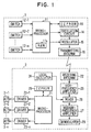
- a keyless entry system comprises, as shown in Fig. 1, a transmitter 1, and a receiver 2 installed on the vehicle to receive radio wave control signals from the transmitter 1 and to drive and control devices installed on the vehicle.
- the receiver 2 executes control operations, for example, to give a locking or unlocking drive signal to a door locking motor installed on a door, and to give an opening drive signal to a trunk opening motor installed on a trunk.
- the transmitter 1 may be contained in a master key to be used for starting the engine of the vehicle and for locking and unlocking the doors of the vehicle or may be an individual transmitter.
- the transmitter 1 comprises a microprocessor 11, i.e., a control unit for controlling all the operations of the transmitter 1, control switches 12-1, 12-2, ... and 12-n, an oscillation circuit 14, a modulator 15, a transmitting antenna 16, and an EEPROM 19, i.e., a memory (storage) unit.
- the control switches 12-1, 12-2, ... and 12-n are used for specifying different functions, such as a door locking function, a door unlocking function, a trunk opening function, a seat position setting function and such, respectively, in a remote control mode. Signals indicating the operation of the control switches 12-1, 12-2, ... and 12-n are applied to the microprocessor 11.
- An ID code identifying the transmitter 1 is stored in an EEPROM 19 connected to the microprocessor 11.
- a rolling code, the contents of information expressed by which changes every time the rolling code is transmitted, and information for generating a transmission code are stored in a DRAM 11a, i.e., an internal memory unit, included in the microprocessor 11.
- the microprocessor 11 decides which one of the control switches 12-1, 12-2, ... and 12-n is operated, and generates a transmission code including a function code expressing a function assigned to the operated control switch.
- the oscillation circuit 14 and the modulator 15 are connected to the microprocessor 11.
- a transmission code generated by the microprocessor 11 is modulated to provide a modulated signal, and a weak radio wave corresponding to the modulated signal is radiated by the transmitting antenna 16.
- the receiver 2 comprises a microprocessor 21, i.e., a control unit for controlling all the operations of the receiver 2, a receiving antenna 22, driving circuits 23-1, 23-2, ... and 23-n, a local oscillator 24, a high-frequency amplifier 25, a mixer 26, a medium-frequency amplifier 27, a demodulator 28 and an EEPROM 29, i.e., a memory unit.
- the weak radio wave transmitted by the transmitter 1 is received by the receiving antenna 22, the radio wave is demodulated by a receiving demodulating unit comprising the local oscillator 24, the high-frequency amplifier 25, the mixer 26, the medium-frequency amplifier 27 and the demodulator 28 to provide a demodulated signal, the demodulated signal is converted into a corresponding digital signal, and the digital signal is applied to the microprocessor 21.
- a receiving demodulating unit comprising the local oscillator 24, the high-frequency amplifier 25, the mixer 26, the medium-frequency amplifier 27 and the demodulator 28 to provide a demodulated signal
- the demodulated signal is converted into a corresponding digital signal
- the digital signal is applied to the microprocessor 21.
- the microprocessor 21 executes a predetermined processing to generate an ID code and a rolling code on the basis of the demodulated signal.
- a code corresponding to the ID code identifying the transmitter 1 is stored in the EEPROM 29 connected to the microprocessor 21.
- Actuators 3-1, 3-2, ... and 3-n installed on the vehicle are connected to the driving circuits 23-1, 23-2, ... and 23-n connected to the microprocessor 21.
- the driving circuits 23-1, 23-2, ... and 23-n provide driving signals according to control signals given thereto to drive the actuators 3-1, 3-2, ... and 3-n. If the actuator 3-1 is a door locking motor, the driving circuit 23-1 provides either a door locking signal for driving the actuator 3-1 for a door locking operation or a door unlocking signal for driving the actuator 3-1 for a door unlocking operation.
- control switches 12-1 and 12-2 of the transmitter 1 are used individually for providing a door locking signal and a door unlocking signal, respectively, in this embodiment because the controlled actuator installed on the door has a locking function and an unlocking function.
- the microprocessor 21 of the receiver 2 gives a control signal requesting a door locking operation or a door unlocking operation to the driving circuit 23-1, and the driving circuit 23-1 gives a driving signal for driving the actuator 3-1, i.e., the door locking motor, for either a door locking operation or a door unlocking operation.
- the control switch 12-2 assigned for door unlocking operation of the transmitter is operated only once if it is desired to unlock only the door beside the driver's seat, the same control switch 12-2 is operated twice within, for example three seconds if it is desired to unlock all the doors of the vehicle.
- control switch is operated twice within a short time, it is possible that the control switch is operated for the second time while a code transmission process started in result of the first operation of the control switch is being executed.
- code transmission processes corresponding to the operations of the control switches 12-1, 12-2, ... and 12-n are surely executed even if the control switches 12-1, 12-2, ... and 12-n are operated a plurality of times within a short time to avoid the foregoing undesirable operation.
- the microprocessor 11 of the transmitter 1 is programmed to execute a main control routine shown in Fig. 2.
- the main control routine is started when any one of the control switches 12-1, 12-2, ... and 12-n is operated.
- An initializing process is executed in step S10, an ID code is read from the EEPROM 19 in step S20, a rolling code (ROL code) is read from the RAM 11a in step S30, and a transmission code is generated by using the ID code and the rolling code in step S40.
- the ID code is peculiar to the transmitter 1. If the ID code is stolen, a locking mechanism controlled by the transmitter 1 may be unlocked by an unauthorized user, which is undesirable from the viewpoint of security. Therefore, the ID code is enciphered by using a progressively changed rolling code obtained by progressively changing a rolling code according to the number of transmission cycles in a predetermined sequence.
- a procedure for generating the transmission code may be performed as disclosed in EP-0697491 (U.S. Application No. 08/510469, JP-A 8-102982), the details of which is incorporated herein by reference. That is, an exclusive OR operation is performed for the rolling code and the ID code, and the result of exclusive OR and the rolling code are rearranged on the basis of a predetermined order of arrangement. A format bits (start bit and stop bit), a function bit, a parity bit and a random number of predetermined bits are added to the rearranged code to generate a transmission code.
- step S50 After the transmission data has been generated in step S40, a determination is made in step S50 to check if a cycle flag is set. Step S50 is repeated until the result in step S50 becomes affirmative (YES). If the result in step S50 is affirmative, step S60 is executed. The cycle flag is set in a subroutine shown in Fig. 6.
- This interrupt subroutine shown in Fig. 6 is executed every 780 ⁇ s.
- a transmission request flag is "1" i.e., the result of a determination made in step S2010 is affirmative
- a data transmission process is executed in step S2020, and then the routine goes to step S2030.
- step S2020 for the data transmission process is skipped and the routine goes to step S2030. If the cycle flag is set at a predetermined cycle of 12.48 ms, i.e., the result of a determination made in step S2030 is affirmative, the cycle flag is set in step S2040 and then the routine goes to step S2050.
- step S2040 is skipped and the routine goes to step S2050. If the cycle flag is set at a predetermined cycle of 6.24 ms, i.e., the result of a determination made in step S2050 is affirmative, a WD timer is cleared in step S2060 and the subroutine is ended. If the cycle flag is not set at the predetermined cycle of 6.24 ms, i.e., the result of a determination made in step S2050 is negative, the subroutine is ended without clearing the WD timer.
- step S60 If the cycle flag is set at the predetermined cycle of 12.48 ms (S2030, S2040) in the subroutine (Fig. 6) and the cycle flag is set, i.e., the result in step S50 of the main routine (Fig. 2) is affirmative, step S60 and the following steps are executed. Consequently, the step S60 and the following steps are executed every 12.48 ms, and the cycle flag is used for determining a main cycle.
- step S60 the cycle flag is cleared and the WD counter is cleared. If the count of the WD counter is not smaller than a fixed value, step S2060 for clearing the WD counter is not executed and the WD counter is reset.
- step S70 the operated control switch among the control switches 12-1. 12-2, ... and 12-n is identified. If the operated control switch is identified, i.e., if the result of a determination made in step S80 is affirmative, a timer monitoring process is executed in step S90, and then a data transmission control routine is executed in step S100.
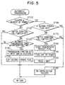
- step S1010 In the data transmission control routine shown in Fig. 4 to be executed by step S100, a determination is made in step S1010 to check whether an ordinary transmission mode is selected or whether an automatic transmission mode is selected. If the ordinary transmission mode is selected, an ordinary transmission mode routine is executed in step S1020, and then the routine goes to step S1040. The transmission request flag is set to "1" during the ordinary transmission mode routine. If the automatic transmission mode is selected, an automatic transmission mode routine is executed in step S1030.
- step S1110 a determination is made in step S1110 to check if the count of a frame transmission counter is not smaller than the number of automatic transmission frames.
- the count of the frame transmission counter is incremented by one every time one frame is transmitted. If the count of the frame transmission counter is less than the number of automatic transmission frames, i.e., if all the frames to be transmitted have not been transmitted (the result of the determination made in step S1110 is negative), a determination is made in step S1120 to check if a switch condition after an input switch filtering process is an all-switch-off condition.
- the switch condition after an input switch filtering process is a switch condition after double coincidence sampling. If the result of the determination made in step S1120 is affirmative, the automatic transmission mode routine is ended, and the routine returns to step S1040 (Fig. 4).
- step S1130 determines whether an automatic transmission timer is set for a time not shorter than an automatic transmission confirmation time. If the automatic transmission timer is set for a time not shorter than the automatic transmission confirmation time, i.e., if the result of the determination made in step S1130 is affirmative, a transmission function bit is set in the switch condition after the input switch filtering process in step S1140, the second memory flag is set in step S1150, and then the routine returns to step S1040 (Fig. 4). If the time for which the automatic transmission timer is less than the automatic transmission confirmation time, i.e., the result of the determination made in step S1130 is negative, the automatic transmission mode routine is ended and the routine returns to step S1040 (Fig. 4).
- step S1160 determines whether the second memory flag is set. If the result of the determination made in step S1160 is negative, a determination is made in step S1170 to check if the switch condition after input switch filtering process is the all-switch-off state. If the result of the determination made in step S1170 is negative, a re-initialization routine is executed in step S1210, the automatic transmission mode routine is ended and the routine returns to step S1040 ( Fig. 4). The re-initialization routine of step S1210 sets a transmission data generation request flag. If the transmission data generation request flag is set, the result of the determination made in step S110 (Fig. 2) is affirmative.
- step S1170 If the switch condition after the input switch filtering process is the all-switch-off condition, i.e., the result of the determination made in step S1170 is affirmative, the transmission request flag is cleared in step S1180, an RF power supply is turned off in step S1190 and a wait mode is set in step S1200. Subsequently, the automatic transmission mode routine is ended and the routine returns to step S1040 (Fig. 4).
- step S1040 (Fig. 4), a determination is mad to check if the switch condition after the input switch filtering process is the all-switch-off condition.
- the automatic transmission timer is cleared in step S1050, the data transmission control routine is ended and the routine returns to step S110 (Fig. 2) if the result of the determination made in step S1040 is affirmative.
- the data transmission control routine is ended without executing step S1050 and the routine returns to step S110 (Fig. 2) if the result of the determination made in step S1040 is negative..
- step S110 (Fig. 2) to check if a transmission data generation is requested.
- the routine returns to step S30 if the result of the determination made in step S110 is affirmative.
- Step S120 (Fig. 3) is executed if the result of the determination made in step S110 is negative.
- An LED output control process is executed in step S120 to notify the operator of acceptance of operation of one of the control switches 12-1, 12-2, ... and 12-n.
- step S130 A determination is made in step S130 to check if an end request is set.
- the end request is set when a predetermined stop migration condition is met. If the end request is not set, i.e., if the result of the determination made in step S130 is negative, step S50 (Fig. 2) and the following steps are repeated.
- the transmission request flag is cleared in step S140, the RF power supply is turned off in step S150, a rolling code updating process is executed in step S160 and the main routine is ended if the result of the determination made in step S130 is affirmative.
- Steps of the procedures to be carried out by the microprocessor 11 of the transmitter 1 have been described in connection with the flow charts shown in Figs. 2 to 5. Operations to be carried out when the door unlocking control switch 12-2 of the transmitter 1 is operated twice to open all the doors will be described in connection with the relevant principal processes shown in Figs. 2 to 5.
- the main routine (Fig. 2) is started and steps S10 to S40 are executed when the control switch 12-2 is operated once.
- the transmission request flag is not yet set, i.e., the result of the determination made in step S2010 is negative, the data transmission process is not executed in step S2020 and the routine goes to S2030.
- the cycle flag is set at predetermined intervals of 12.48 ms (S2030, S2040)
- the result of the determination made in step S50 of the main routine is affirmative, and then steps S60 to S90 are executed, and the data transmission control routine of step S100 is executed.
- step S1010 In the data transmission control routine shown in Fig. 4 to be executed in step S100, it is decided in step S1010 that the ordinary transmission mode is selected, and the transmission request flag is set to "1" while the ordinary transmission mode process is being executed in step S1020. Consequently, in the subroutine shown in Fig. 6, the result of the determination made in step S2010 is affirmative, and the data transmission process is executed in step S2020. When the result of the determination made in step S1040 is affirmative, the automatic transmission timer is cleared in step S1050, and the routine returns to step S110 (Fig. 2).
- step S110 The result of the determination made in step S110 is negative, the LED output control process is executed in step S120 and, since the result of the determination made in step S130 is negative, step S50 and the following steps are repeated (Fig. 2).
- step S100 In the second cycle of the data transmission control process executed in step S100, it is decided that the automatic transmission mode is selected in step S1010 (Fig. 4) and the automatic transmission mode routine is executed in step S1030.
- step S1030 if all the frames to be transmitted have not been transmitted, i.e., the result of the determination made in step S1110 is negative, a determination is made in step S1120 to check if all the control switches after the input switch filtering process are in the OFF state. If the control switch 12-2 is not operated, all the control switches are in the OFF state, i.e., the result of the determination made in step S1120 is affirmative, the automatic transmission mode routine is ended and the routine returns to step S1040 (Fig. 4).
- step S1120 If the control switch 12-2 is operated before all the frames to be transmitted are transmitted, not all the control switches are in the OFF state, i.e., the result of the determination made in step S1120 is negative. Therefore, if the result of the determination made in step S1130 is affirmative, a signal entered by operating the control switch 12-2 for the second time is set as a function bit to be transmitted in the second transmission cycle, and the second memory flag is set in step S1150.
- step S1040 Fig. 4
- step S1040 Since the result of the determination made in step S1040 is negative, the automatic transmission timer clearing process of step S1050 is not executed and the routine returns to step S110. Since the result of the determination made in step S110 is negative, the LED output control process is executed in step S120. Since the result of the determination made in step S130 is negative, the routine returns to step S50 and the data transmission control routine is executed again in step S100.
- step S1140 a transmission function bit corresponding to the second operation is set in step S1140, the second memory flag is set in step S1150. Therefore, the result of the determination made in step S1110 becomes affirmative upon the completion of the first data transmission cycle and the step S1160 is executed. Since the second memory flag is set, the re-initialization routine is executed in step S1210.
- step S1040 The result of the determination made subsequently in step S1040 is affirmative, the automatic transmission timer is cleared in step S1050, and then the routine returns to step S110 (Fig. 2). Since a transmission data generation request is set by the re-initialization routine in step S1210, the result of the determination made in step S110 is affirmative and then steps S30 to S90 are executed to transmit data in result of the second operation of the control switch.
- step S100 shown in Fig. 4
- step S1010 it is decided in step S1010 that the automatic transmission mode is selected, and the automatic transmission mode routine is executed in step S1030.
- step S1120 determines whether the switch condition after the input switch filtering process is the all-switch-off condition. Since the control switch 12-2 is not operated, the switch condition after the input switch filtering process is the all-switch-off condition, i.e., the result of the determination made in step S1120 is affirmative, the automatic transmission mode routine is ended and the routine returns to step S1040 (Fig. 4). The result of the determination made in step S1040 is affirmative, and the automatic transmission timer is cleared in step S1050.
- step S1160 Upon the completion of data transmission for the second operation of the control switch, i.e., the result of the determination made in step S1110 is affirmative, step S1160 is executed. Since the second memory flag is not set, i.e., the result of the determination made in step S1160 is negative, step S1170 is executed.
- step S1170 Since the switch condition after the input switch filtering process is the all-switch-off condition, i.e., the result of the determination made in step S1170 is affirmative, the transmission request flag is cleared in step S1180, the RF power supply is turned off in step S1190, and the wait mode is set in step S1200.
- the automatic transmission mode routine is ended, the routine returns to the subroutine shown in Fig. 4, the subroutine shown in Fig. 4 is ended, and then step S110 (Fig. 2) and the following steps are executed. Since the predetermined stop migration condition is met, the result of the determination made in step S130 (Fig. 3) is affirmative, the transmission request flag is cleared in step S140, the RF power supply is turned off in step S150, the rolling code updating process is executed in step S160 and the main routine is ended.
- the door unlocking control switch 12-2 of the transmitter it is necessary only to operate the door unlocking control switch 12-2 of the transmitter once if it is desired to open only the door beside the driver's seat, and it is necessary only to operate the same door unlocking control switch 12-2 of the transmitter 1 twice within, for example, three seconds if it is desired to unlock all the doors.
- the control switch is operated for the second time while the code transmission process is being executed in result of the first operation of the same control switch if the control switch is operated twice within the short time, the code transmission process corresponding to the second operation of the control switch can surely be executed after the code transmission process corresponding to the first operation of the control switch has been completed.
- the transmitter 1 is capable of surely executing the code transmission process corresponding to the second operation of the control switch after the completion of the code transmission process corresponding to the first operation of the control switch even if the control switch is operated for the second time while the code transmission process corresponding to the first operation of the control switch is being executed; that is, if the operator operates the control switch 12-2 twice with an intention to unlock all the doors, the door beside the driver's seat is unlocked by the transmission process corresponding to the first operation of the control switch and the rest of the doors are unlocked by the transmission process corresponding to the second operation of the control switch, which conforms the intention of the operator.
- the function codes specified by the states of operation of the control switches 12-1, 12-2, ... and 12-n are stored if the control switches 12-1, 12-2, ... and 12-n are operated for the second time during transmission processes corresponding to the first operation of the control switches 12-1, 12-2, ... and 12-n.
- the states of operation indicating which of control switches 12-1, 12-2, ... and 12-n are operated may be stored, function codes may be specified on the basis of the stored states of operation after the completion of the preceding transmission process, and remote control signals obtained by converting the function codes thus specified may be transmitted.
- the keyless entry system operates in the same mode, for example, when the control switches are operated to unlock the door and to unlock the trunk instead of signifying an operation to unlock the door beside the driver's seat by the one operation of the control switch and an operation to unlock all the doors by the two operations of the same control switch.
- the operator expecting that both the operations specified by operating the control switch twice be achieved will consider that the keyless entry system is malfunctioning if the trunk is opened and the door is not unlocked. Therefore, it is effective to carry out the transmission processes corresponding to the two operations of the control switches.
- the keyless entry system operates in the same mode when the control switch is operated three or more times.
- states of the second and the third operation of the control switch or function codes specified by the states of the second and the third operation of the control switch may be stored, a transmission process corresponding to the second operation of the control switch may be executed after the completion of the transmission process corresponding to the first operation of the control switch, and transmission corresponding to the second operation of the control switch may be executed.
- control switches 12-1, 12-2, ... and 12-n are operated a plurality of times, a state of the last operation or a function code specified by the state of the second operation may be stored.
- the receiver 2 is provided with the driving circuits 23-1, 23-2, ... and 23-n, to give driving signals to the actuators 3-1, 3-2, ... and 3-n on the basis of function codes determined by analyzing the received remote control signals.
- the receiver may only analyze the function codes and such, and the function codes may be received by an additional body ECU installed in the vehicle, and driving signals may be given to the actuators 3-1, 3-2, ... and 3-n by an ECU (electronic control unit) mounted in a vehicle.
Landscapes
- Engineering & Computer Science (AREA)
- Computer Networks & Wireless Communication (AREA)
- Physics & Mathematics (AREA)
- General Physics & Mathematics (AREA)
- Lock And Its Accessories (AREA)
- Selective Calling Equipment (AREA)
Claims (10)
- Un système de commande d'entrée sans clef (1, 2) ayant un dispositif d'entrée (3-1 à 3-n), comprenant:un interrupteur de commande (12-1 à 12-n) pour sélectionner les fonctions devant être effectuées par le dispositif d'entrée ;une unité d'émission (11, 16) pour convertir en un signal de commande à distance d'une onde radio un code de fonction indiquant le dispositif d'entrée et une opération devant être effectuée par le dispositif d'entrée spécifié par l'actionnement de l'interrupteur de commande, et pour produire le signal d'onde radio de commande; etune unité de commande d'émission (11) pour stocker des données sur un état de fonctionnement de l'interrupteur de commande effectué pour un processus d'émission de code ou le code de fonction spécifié par l'état de fonctionnement si l'interrupteur de commande est actionné pendant que l'unité de transmission est engagé dans un processus d'émission de signal, pour convertir en un signal correspondant de commande à distance d'une onde radio le code de fonction spécifié par les données stockées sur l'état de fonctionnement ou le code de fonction stocké, et en amenant l'unité d'émission à produire le signal de commande à distance après l'achèvement d'une émission précédente.
- Le système selon la revendication 1, dans lequel :l'unité de commande d'émission (11) stocke des données sur l'état d'un dernier fonctionnement de l'interrupteur ou un code de fonction spécifié par le dernier fonctionnement de l'interrupteur si l'interrupteur de commande (12-1 à 12-n) est actionné une pluralité de fois pendant que l'unité d'émission est engagé dans un processus d'émission.
- Le système selon la revendication 1 ou 2, dans lequel :l'unité de commande d'émission (11) détermine que le fonctionnement de l'interrupteur de commande (12-1 à 12-n) est incorrect si la durée de fonctionnement de l'interrupteur de commande est inférieure à une limite inférieure prédéterminée et désactive l'opération devant être utilisée pour spécifier le code de fonction devant être émis par l'unité d'émission (16).
- Le système selon l'une quelconque des revendications de 1 à 3, comprenant en outre :un récepteur (2) installé sur un véhicule pour recevoir le signal de commande à distance et commander le dispositif d'entrée (3-1 à 3-n) installé sur le véhicule.
- Le système selon l'une quelconque des revendications de 1 à 3, comprenant en outre :un récepteur (2) pour recevoir le signal de commande à distance et commander le dispositif d'entrée (3-1 à 3-n) afin d'obtenir le fonctionnement spécifié par le signal de commande à distance.
- Le système selon la revendication 5, dans lequel :le dispositif d'entrée (3-1 à 3-n) a une pluralité de fonctions de déverrouillage de portières pour déverrouiller une pluralité de portières d'un véhicule, qui peuvent être spécifiées en actionnant l'interrupteur de commande (12-1 à 12-n) ; etle récepteur (2) déverrouille seulement une portière située à côté du siège du conducteur en réponse au signal de commande à distance correspondant au code de fonction indiquant la fonction de déverrouillage de portières, et déverrouille d'autres portières situées à côté d'autres sièges que le siège du conducteur en réponse à un autre signal de commande à distance correspondant au code de fonction indiquant la même fonction de déverrouillage de portières dans une période de temps prédéterminée après la réception d'un signal antérieur de commande à distance.
- Le système selon la revendication 5 ou 6, dans lequel :le signal de commande à distance comprend un code d'identification ID spécifique d'un utilisateur, en plus du code de fonction ; etle récepteur (2) analyse le signal de commande à distance pour vérifier si le code ID d'identification coïncide avec un code ID d'identification antérieurement stocké dans celui-ci, et actionne le dispositif d'entrée (3-1 à 3-n) pour un fonctionnement spécifié par le code de fonction inclus dans le signal de commande à distance seulement lorsque le code ID d'identification coïncide avec le code d'identification ID antérieurement stocké dans celui-ci.
- Un procédé de commande d'entrée sans clef comprenant en outre les opérations consistant à :actionner un interrupteur (12-1 à 12-n) d'un émetteur (1) pour ordonner un premier fonctionnement prédéterminé d'une pluralité d'actionneurs (3-1 à 3-n);émettre, de l'émetteur (1) vers un récepteur (2), un premier signal de commande à distance indiquant le premier fonctionnement prédéterminé des actionneurs (3-1 à 3-n) ;vérifier si l'interrupteur (12-1 à 12-n) est actionné de nouveau pour un second fonctionnement prédéterminé des actionneurs (3-1 à 3-n), tandis que l'émetteur (1) est dans un processus d'émission de signal pour le premier fonctionnement prédéterminé des actionneurs (3-1 à 3-n) ;stocker dans l'émetteur (1) un autre actionnement de l'interrupteur (12-1 à 12-n) pour le second fonctionnement des actionneurs (3-1 à 3-n) si l'autre actionnement se produit dans une période de temps prédéterminée correspondant au fonctionnement en émission de l'émetteur (1) ;après achèvement de l'opération d'émission du premier signal de commande à distance, émettre depuis l'émetteur (1) vers le récepteur (2) un second signal de commande à distance indiquant le second fonctionnement prédéterminé des actionneurs (3-1 à 3-n) en réponse à l'autre fonctionnement stocké de l'interrupteur (12-1 à 12-n) ; etcommander les actionneurs (3-1 à 3-n) par le récepteur (2) en réponse au premier signal reçu de commande à distance et au second signal de commande à distance pour effectuer respectivement le premier fonctionnement prédéterminé et le second fonctionnement prédéterminé des actionneurs.
- Le procédé de commande selon la revendication 8, dans lequel :le premier fonctionnement prédéterminé des actionneurs (3-1 à 3-n) est le déverrouillage d'une portière d'un véhicule située à côté du siège du conducteur; etle second fonctionnement prédéterminé des actionneurs (3-1 à 3-n) est le déverrouillage des autres portières du véhicule.
- Le procédé de commande selon la revendication 8, dans lequel :le nombre d'actionnements de l'interrupteur (12-1 à 12-n) est établi différemment entre le premier fonctionnement prédéterminé et le second fonctionnement prédéterminé.
Applications Claiming Priority (3)
| Application Number | Priority Date | Filing Date | Title |
|---|---|---|---|
| JP24106097 | 1997-09-05 | ||
| JP241060/97 | 1997-09-05 | ||
| JP24106097A JP3339378B2 (ja) | 1997-09-05 | 1997-09-05 | キーレスエントリシステム用の送信機及びキーレスエントリシステム |
Publications (2)
| Publication Number | Publication Date |
|---|---|
| EP0900902A1 EP0900902A1 (fr) | 1999-03-10 |
| EP0900902B1 true EP0900902B1 (fr) | 2004-08-25 |
Family
ID=17068715
Family Applications (1)
| Application Number | Title | Priority Date | Filing Date |
|---|---|---|---|
| EP98116829A Expired - Lifetime EP0900902B1 (fr) | 1997-09-05 | 1998-09-04 | Commande d'entrée sans clef et émetteur associé |
Country Status (4)
| Country | Link |
|---|---|
| US (1) | US6396389B1 (fr) |
| EP (1) | EP0900902B1 (fr) |
| JP (1) | JP3339378B2 (fr) |
| DE (1) | DE69825827T2 (fr) |
Families Citing this family (24)
| Publication number | Priority date | Publication date | Assignee | Title |
|---|---|---|---|---|
| JP4603640B2 (ja) * | 1999-04-14 | 2010-12-22 | 富士通テン株式会社 | 遠隔制御装置および遠隔制御用受信装置 |
| JP3844908B2 (ja) * | 1999-05-27 | 2006-11-15 | アルプス電気株式会社 | 車両用遠隔制御装置 |
| JP3562387B2 (ja) * | 1999-06-04 | 2004-09-08 | トヨタ自動車株式会社 | 車載機器遠隔制御装置 |
| JP4753482B2 (ja) * | 2001-03-19 | 2011-08-24 | 文化シヤッター株式会社 | 開閉装置の通信システム、非開閉装置側通信装置および開閉装置側通信装置 |
| US6954134B2 (en) | 2001-09-28 | 2005-10-11 | Alps Automotive, Inc. | Apparatus and method for timing an output of a remote keyless entry system |
| US6864800B2 (en) | 2001-09-28 | 2005-03-08 | Alps Automotive, Inc. | Apparatus and method of calibrating a keyless transmitter |
| US6643598B2 (en) * | 2001-09-28 | 2003-11-04 | Alps Automotive, Inc. | Apparatus and method for calibrating a timing circuit in a remote keyless entry system using programmable commands |
| KR20040022482A (ko) * | 2002-09-07 | 2004-03-16 | 현대자동차주식회사 | 자동차의 키레스 엔트리장치 제어방법 |
| US7898387B2 (en) * | 2003-01-22 | 2011-03-01 | Chrysler Group Llc | Portable remote transmitter to remotely control a vehicle function |
| JP4321349B2 (ja) * | 2004-05-12 | 2009-08-26 | 株式会社デンソー | スマートエントリシステム |
| JP4679933B2 (ja) * | 2005-03-02 | 2011-05-11 | アルプス電気株式会社 | キーレスエントリー装置 |
| US8332645B2 (en) * | 2006-09-11 | 2012-12-11 | Yeda Research And Development Co. Ltd | Method, apparatus and product for RFID authentication |
| JP2008084120A (ja) * | 2006-09-28 | 2008-04-10 | Fujitsu Ten Ltd | 電子制御装置 |
| JP4747117B2 (ja) * | 2007-02-19 | 2011-08-17 | 株式会社東海理化電機製作所 | 送信機 |
| JP5199923B2 (ja) * | 2009-03-10 | 2013-05-15 | 富士重工業株式会社 | キーレスエントリーシステム |
| JP2015074958A (ja) | 2013-10-11 | 2015-04-20 | アルプス電気株式会社 | キーレスエントリシステム |
| US9807172B2 (en) * | 2013-10-18 | 2017-10-31 | At&T Intellectual Property I, L.P. | Mobile device intermediary for vehicle adaptation |
| US9203843B2 (en) | 2013-11-08 | 2015-12-01 | At&T Mobility Ii Llc | Mobile device enabled tiered data exchange via a vehicle |
| US9892199B2 (en) * | 2013-12-20 | 2018-02-13 | Lenovo (Singapore) Pte. Ltd. | Specialized virtual personal assistant setup |
| CN106856037A (zh) * | 2015-12-08 | 2017-06-16 | 重庆尊来科技有限责任公司 | 一种双波四码汽车遥控发射设计方案 |
| CN106920376A (zh) * | 2015-12-27 | 2017-07-04 | 重庆尊来科技有限责任公司 | 一种双波双码接收设计方案 |
| CN106920375A (zh) * | 2015-12-27 | 2017-07-04 | 重庆尊来科技有限责任公司 | 一种双波四码汽车遥控接收器 |
| JP6664100B2 (ja) * | 2016-10-07 | 2020-03-13 | パナソニックIpマネジメント株式会社 | 車載器、及び車両用無線通信システム |
| DE102017200380A1 (de) * | 2017-01-11 | 2018-07-12 | Ford Global Technologies, Llc | Verfahren zum Verriegeln, Entriegeln und Starten eines Fahrzeugs |
Family Cites Families (9)
| Publication number | Priority date | Publication date | Assignee | Title |
|---|---|---|---|---|
| US4890108A (en) | 1988-09-09 | 1989-12-26 | Clifford Electronics, Inc. | Multi-channel remote control transmitter |
| JP3383674B2 (ja) | 1992-03-26 | 2003-03-04 | 松下電工株式会社 | 照明装置 |
| JPH06153274A (ja) | 1992-11-10 | 1994-05-31 | Toshiba Corp | 遠隔監視制御装置 |
| JPH07303286A (ja) * | 1994-05-06 | 1995-11-14 | Nissan Motor Co Ltd | 送受信機を用いた制御装置 |
| JPH07303386A (ja) | 1994-05-09 | 1995-11-14 | Brother Ind Ltd | ミシンモータの制御装置 |
| JP3319230B2 (ja) * | 1994-08-05 | 2002-08-26 | 株式会社デンソー | 遠隔操作装置 |
| DE19530724A1 (de) * | 1995-08-18 | 1997-02-20 | Kiekert Ag | Steueranlage für ein Kraftfahrzeug mit Mehrfunktionstaste einer Fernbedienungseinrichtung |
| EP0769435A3 (fr) | 1995-10-17 | 1999-04-28 | DesignTech International, Inc. | Module de commande d'une unité auxiliaire pour utilisation avec un module de commande à distance existant dans un véhicule |
| US5955981A (en) * | 1995-12-12 | 1999-09-21 | Rangan; Karur S. | Security for remote operation devices |
-
1997
- 1997-09-05 JP JP24106097A patent/JP3339378B2/ja not_active Expired - Lifetime
-
1998
- 1998-09-04 DE DE1998625827 patent/DE69825827T2/de not_active Expired - Lifetime
- 1998-09-04 EP EP98116829A patent/EP0900902B1/fr not_active Expired - Lifetime
- 1998-09-04 US US09/148,418 patent/US6396389B1/en not_active Expired - Lifetime
Also Published As
| Publication number | Publication date |
|---|---|
| JP3339378B2 (ja) | 2002-10-28 |
| DE69825827D1 (de) | 2004-09-30 |
| DE69825827T2 (de) | 2005-09-01 |
| JPH1181764A (ja) | 1999-03-26 |
| EP0900902A1 (fr) | 1999-03-10 |
| US6396389B1 (en) | 2002-05-28 |
Similar Documents
| Publication | Publication Date | Title |
|---|---|---|
| EP0900902A1 (fr) | Commande d'entrée sans clef et émetteur associé | |
| US7109843B2 (en) | Remote control system for controlling a vehicle with priority of control access being assigned to the most recent user of the vehicle | |
| JP3632463B2 (ja) | 車載機器遠隔制御装置 | |
| US6127922A (en) | Vehicle security system with remote systems control | |
| US7501931B2 (en) | Vehicular remote locking and unlocking control apparatus | |
| US6944528B2 (en) | Wireless communication system for vehicle | |
| EP0787875A2 (fr) | Emetteur-récepteur portable à retard de phase pour un système d'entrée sans clé dans un véhicule | |
| JPS63574A (ja) | 解錠制御装置 | |
| WO2007081586A1 (fr) | Émetteur et procédé pour la transmission d'un signal de commande radiofréquence | |
| KR20080094592A (ko) | 원격 제어 시스템 및 방법 | |
| JPH07303286A (ja) | 送受信機を用いた制御装置 | |
| EP0985789B1 (fr) | Appareil de commande à distance et méthode de commande à distance | |
| EP1614592B1 (fr) | Dispositif d'entrée sans clé | |
| US7148584B2 (en) | Lock control apparatus for use in vehicle | |
| EP1339026B1 (fr) | Appareil à clé électronique pour véhicule et procédé d'annulation du blocage pour dispositif de blocage de rotation | |
| JPH02162997A (ja) | 自動車用遠隔操作装置 | |
| JP3230469B2 (ja) | 車載機器遠隔操作装置 | |
| JP2002339612A (ja) | 車両用電子キー装置 | |
| US6959181B2 (en) | Transmitter device having means for automatically transmitting data remaining therein upon its re-activation | |
| JP2001040921A (ja) | スマートエントリシステム | |
| JP4585961B2 (ja) | 無線通信制御システム | |
| JP2000045589A (ja) | キーレスエントリシステム及びその施解錠制御方法 | |
| JP2921170B2 (ja) | キー閉じ込め防止装置 | |
| JP3226385B2 (ja) | 車輌用ロック制御装置 | |
| JP3344445B2 (ja) | 遠隔操作装置 |
Legal Events
| Date | Code | Title | Description |
|---|---|---|---|
| PUAI | Public reference made under article 153(3) epc to a published international application that has entered the european phase |
Free format text: ORIGINAL CODE: 0009012 |
|
| AK | Designated contracting states |
Kind code of ref document: A1 Designated state(s): DE FR GB |
|
| AX | Request for extension of the european patent |
Free format text: AL;LT;LV;MK;RO;SI |
|
| 17P | Request for examination filed |
Effective date: 19990416 |
|
| AKX | Designation fees paid |
Free format text: DE FR GB |
|
| 17Q | First examination report despatched |
Effective date: 20030625 |
|
| GRAP | Despatch of communication of intention to grant a patent |
Free format text: ORIGINAL CODE: EPIDOSNIGR1 |
|
| GRAS | Grant fee paid |
Free format text: ORIGINAL CODE: EPIDOSNIGR3 |
|
| GRAA | (expected) grant |
Free format text: ORIGINAL CODE: 0009210 |
|
| AK | Designated contracting states |
Kind code of ref document: B1 Designated state(s): DE FR GB |
|
| REG | Reference to a national code |
Ref country code: GB Ref legal event code: FG4D |
|
| REF | Corresponds to: |
Ref document number: 69825827 Country of ref document: DE Date of ref document: 20040930 Kind code of ref document: P |
|
| ET | Fr: translation filed | ||
| PLBE | No opposition filed within time limit |
Free format text: ORIGINAL CODE: 0009261 |
|
| STAA | Information on the status of an ep patent application or granted ep patent |
Free format text: STATUS: NO OPPOSITION FILED WITHIN TIME LIMIT |
|
| REG | Reference to a national code |
Ref country code: GB Ref legal event code: 746 Effective date: 20050704 |
|
| 26N | No opposition filed |
Effective date: 20050526 |
|
| REG | Reference to a national code |
Ref country code: FR Ref legal event code: PLFP Year of fee payment: 19 |
|
| REG | Reference to a national code |
Ref country code: FR Ref legal event code: PLFP Year of fee payment: 20 |
|
| PGFP | Annual fee paid to national office [announced via postgrant information from national office to epo] |
Ref country code: FR Payment date: 20170928 Year of fee payment: 20 Ref country code: GB Payment date: 20170921 Year of fee payment: 20 Ref country code: DE Payment date: 20170928 Year of fee payment: 20 |
|
| REG | Reference to a national code |
Ref country code: DE Ref legal event code: R071 Ref document number: 69825827 Country of ref document: DE |
|
| REG | Reference to a national code |
Ref country code: GB Ref legal event code: PE20 Expiry date: 20180903 |
|
| PG25 | Lapsed in a contracting state [announced via postgrant information from national office to epo] |
Ref country code: GB Free format text: LAPSE BECAUSE OF EXPIRATION OF PROTECTION Effective date: 20180903 |