EP0900516B1 - Verfahren und Einrichtung zur Aufnahme von Sämlingen aus einer Sämlingschale - Google Patents
Verfahren und Einrichtung zur Aufnahme von Sämlingen aus einer Sämlingschale Download PDFInfo
- Publication number
- EP0900516B1 EP0900516B1 EP98101478A EP98101478A EP0900516B1 EP 0900516 B1 EP0900516 B1 EP 0900516B1 EP 98101478 A EP98101478 A EP 98101478A EP 98101478 A EP98101478 A EP 98101478A EP 0900516 B1 EP0900516 B1 EP 0900516B1
- Authority
- EP
- European Patent Office
- Prior art keywords
- seedling
- tray
- storage cells
- rods
- row
- Prior art date
- Legal status (The legal status is an assumption and is not a legal conclusion. Google has not performed a legal analysis and makes no representation as to the accuracy of the status listed.)
- Expired - Lifetime
Links
- 238000000034 method Methods 0.000 title claims abstract description 19
- 210000000352 storage cell Anatomy 0.000 claims abstract description 107
- 230000007246 mechanism Effects 0.000 claims description 52
- 238000003780 insertion Methods 0.000 claims description 47
- 230000037431 insertion Effects 0.000 claims description 47
- 239000012530 fluid Substances 0.000 claims description 20
- 230000003028 elevating effect Effects 0.000 claims description 2
- 210000004027 cell Anatomy 0.000 description 50
- 239000011295 pitch Substances 0.000 description 39
- 238000010276 construction Methods 0.000 description 13
- 230000006835 compression Effects 0.000 description 7
- 238000007906 compression Methods 0.000 description 7
- 238000001514 detection method Methods 0.000 description 7
- 238000002054 transplantation Methods 0.000 description 5
- 238000011144 upstream manufacturing Methods 0.000 description 3
- 238000010899 nucleation Methods 0.000 description 2
- PPBRXRYQALVLMV-UHFFFAOYSA-N Styrene Chemical compound C=CC1=CC=CC=C1 PPBRXRYQALVLMV-UHFFFAOYSA-N 0.000 description 1
- 238000007792 addition Methods 0.000 description 1
- 210000000078 claw Anatomy 0.000 description 1
- 238000005520 cutting process Methods 0.000 description 1
- 230000001419 dependent effect Effects 0.000 description 1
- 238000011161 development Methods 0.000 description 1
- 230000018109 developmental process Effects 0.000 description 1
- 230000000694 effects Effects 0.000 description 1
- 238000003825 pressing Methods 0.000 description 1
- 238000005096 rolling process Methods 0.000 description 1
- 239000000725 suspension Substances 0.000 description 1
Images


Classifications
-
- A—HUMAN NECESSITIES
- A01—AGRICULTURE; FORESTRY; ANIMAL HUSBANDRY; HUNTING; TRAPPING; FISHING
- A01G—HORTICULTURE; CULTIVATION OF VEGETABLES, FLOWERS, RICE, FRUIT, VINES, HOPS OR SEAWEED; FORESTRY; WATERING
- A01G9/00—Cultivation in receptacles, forcing-frames or greenhouses; Edging for beds, lawn or the like
- A01G9/08—Devices for filling-up flower-pots or pots for seedlings; Devices for setting plants or seeds in pots
- A01G9/086—Devices for repotting
-
- A—HUMAN NECESSITIES
- A01—AGRICULTURE; FORESTRY; ANIMAL HUSBANDRY; HUNTING; TRAPPING; FISHING
- A01C—PLANTING; SOWING; FERTILISING
- A01C11/00—Transplanting machines
- A01C11/02—Transplanting machines for seedlings
- A01C11/025—Transplanting machines using seedling trays; Devices for removing the seedlings from the trays
-
- Y—GENERAL TAGGING OF NEW TECHNOLOGICAL DEVELOPMENTS; GENERAL TAGGING OF CROSS-SECTIONAL TECHNOLOGIES SPANNING OVER SEVERAL SECTIONS OF THE IPC; TECHNICAL SUBJECTS COVERED BY FORMER USPC CROSS-REFERENCE ART COLLECTIONS [XRACs] AND DIGESTS
- Y10—TECHNICAL SUBJECTS COVERED BY FORMER USPC
- Y10S—TECHNICAL SUBJECTS COVERED BY FORMER USPC CROSS-REFERENCE ART COLLECTIONS [XRACs] AND DIGESTS
- Y10S47/00—Plant husbandry
- Y10S47/901—Plant container with flats, filling, planting, or conveying
Definitions
- the present invention relates to a method and a device for picking up seedlings from a seedling tray, and inparticular for picking up seedlings from a plurality of seedling storage cells formed in a seedling tray.
- the conventional seedling tray transporting apparatus is constructed with a seedling tray 113, in which a plurality of seedling storage cells 112 are embossed in a sheet form tray body 111, and a transporting member 115 transversely extending between a pair of transporting strips 114, 114 (only one is shown), being inserted between adjacent seedling storage cells 112, 112.
- a pair of transporting strips 114, 114 are intermittently driven at a predetermined pitch for driving the seedling storage cells 112 by the transporting member 115 to stop each of the seedling storage cells at a predetermined seedling picking up position, at which a seedling picking up claw 116 is provided.
- the seedling tray is stopped when the arithmetically calculated transporting distance matches with the predetermined pitch. Therefore, it is possible that the actual transporting distance and the calculated transporting distance become inconsistent due to accumulated error of a measured value to be a reference in calculation of the transporting distance or a play in the transporting mechanism portion of the seedling tray.
- the position of the seedling pushing rod and the rod insertion hole in the bottom portion of the seedling storage cells of the seedling tray causes offset to make insertion of the seedling pushing rod into the seedling storage cells to thus make it impossible to pick-up the seedling from the seedling tray.
- the seedling tray in the transporting path of the seedling tray, it is typical to arrange a guide rail or the like so that the seedling tray may travel in straight.
- the seedling tray in certain setting of the gap between the guide rail and the seedling tray, the seedling tray may be transported in the tilted attitude.
- the seedling pushing rod and the rod insertion hole in the bottom portion of the seedling storage cells of the seedling tray become offset to each other to make it impossible to pick-up the seedling from the seedling tray.
- transportation of the seedling tray in the tilted attitude can be caused when the tray is worn or deformed.
- the prior art document WO 94 03040 A discloses a method and an apparatus for picking up seedlings from a seedling tray.
- the seedlings are picked up per each row of storage cells from in alignment at a predetermined pitch.
- tray positioning rods pegs linked together and actuated by cylinders
- the pegs move perpendicular to the moving direction of the tray. Further, seedling pushing rods perform an inserting operation.
- the trays have, in addition to holes in the bottom walls thereof for being used to push seedlings by means of seedling pushing rods, holes in the side walls for being used to receive pegs for indexing the tray. Further, the tray is (or can be) moved while being in a vertical position.
- rod insertion holes of the seedling storage cells are used for positioning the seedling tray as well as for pushing seedlings.
- the tray positioning rods according to the present invention are provided in front of the seedling pushing rods and beneath the tray to be positioned.
- the tray positioning rods according to the present invention are provided for positioning the tray. According to the present invention, the tray is moved while the seedlings are provided in an upright position and the tray positioning rods as well as the seedling pushing rods are provided so as to contact the trays by means of holes in the bottom walls thereof, while the trays are moved in a horizontal position.
- a seedling tray in which a plurality of seedling storage cells are formed, is positioned at a predetermined position and an insertion of seedling pushing rods is performed in the positioned condition of the seedling tray.
- a device for picking up seedlings from a seedling tray comprises tray positioning rods for positioning the seedling tray at the predetermined position and seedling pushing rods to be inserted into respective of the seedling storage cells with maintaining the seedling tray at the condition positioned at the predetermined position.
- a method for picking up seedlings from a seedling tray by inserting a seedling pushing rod into rod insertion holes formed in bottoms of respective of seedling storage cells per each row of the seedling storage cells formed in alignment at a predetermined pitch in the seedling tray transported in one direction comprises the steps of:
- the seedling can be securely picked up with accurately opposing the seedling storage cells and the seedling pushing rods even when the seedling tray is transported in tilted fashion and furthermore even when wearing or deformation is caused in the seedling tray.
- the tray positioning rods may be inserted into some of the seedling storage cells in a row other than a row of the seedling storage cells, to which the seedling pushing rods are about inserted.
- the seedling tray may be positioned by inserting the tray positioning rod into some of the seedling storage cells in Nth row and the seedling pushing rods are inserted into the seedling storage cells in (N+1)th row.
- the seedling tray may be positioned by inserting the tray positioning rod into some of the seedling storage cells in Nth row, the tray positioning rod is moved in a magnitude corresponding to an arrangement pitch of the seedling storage cells, toward downstream in a transporting direction of the seedling tray with maintaining the condition where the tray positioning rod is inserted into some of the seedling storage cells, and the seedling pushing rods are inserted into respective of the seedling storage cells in (N+1)th row.
- the seedling tray may be positioned by abutting the tray positioning rod to a front end face of the seedling tray, the seedling pushing rods are inserted into respective of the seedling storage cells in a Nth row for picking up the seedling stored therein, subsequently, the seedling tray is positioned by inserting the tray positioning rod into some of the seedling storage cells in Nth row, the tray positioning rod is moved in a magnitude corresponding to an arrangement pitch of the seedling storage cells, toward downstream in a transporting direction of the seedling tray with maintaining the condition where the tray positioning rod is inserted into some of the seedling storage cells, and the seedling pushing rods are inserted into respective of the seedling storage cells in (N+1)th row.
- a plurality of tray positioning holes for inserting the tray position rod in alignment at predetermined interval may be formed in the seedling tray, and the seedling tray is positioned by inserting the tray positioning rod in the tray positioning hole.
- the tray positioning rod may be shifted in the magnitude corresponding to the arrangement pitch of the seedling storage cells toward downstream side of a transporting direction of the seedling tray with maintaining a condition where the tray positioning rod is inserted in some of the tray positioning hole, and then insertion of the seedling pushing rods into the seedling storage cells is performed.
- the seedling tray can be transported by a predetermined arrangement pitch. Also, it is not necessary to position the seedling tray after once transport for the predetermined arrangement pitch. Furthermore, the front end face of the seedling tray is abutted on the tray positioning rod to initially position the seedling tray accurately.
- the dedicated tray positioning holes are formed so that the tray positioning rods are inserted into the dedicated tray positioning holes without inserting the same into openings at the bottom of the seedling storage cells. Therefore, the seedling tray or the seedling storage cells may not be damaged by the tray positioning rods during seedling pick-up operation.
- the method further comprises the use of seedling holding needles to be downwardly shifted into the seedling storage cells from upper surface opening thereof for piercing and holding the seedling stored in the seedling storage cells by the seedling holding needles. Then, the seedling pushing rods are elevated upwardly to abut onto the bottom surface of the seedling pierced and held by the seedling holding needles under pressure for pushing up the seedling by elevating the seedling holding needles and the seedling pushing rods at the same speed.
- a device for picking up seedlings from a seedling tray per each row of the seedling storage cells formed in alignment at a predetermined pitch in the seedling tray transported in one direction comprises:
- a device for picking up seedlings from a seedling tray per each row of the seedling storage cells formed in alignment at a predetermined pitch in the seedling tray transported in one direction comprises:
- a device for picking up seedlings from a seedling tray per each row of the seedling storage cells formed in alignment at a predetermined pitch in the seedling tray transported in one direction comprises:
- the device may further comprise a tray transporting device intermittently transporting the seedling tray by shifting in the magnitude corresponding to arrangement pitch of the seedling storage cells toward downstream side in the transporting direction of the seedling tray with maintaining the condition where the tray positioning rod is inserted into some of the seedling storage cell in the seedling tray.
- the tray position rod and the seedling pushing rods may be arranged with an interval corresponding to the arrangement pitch of the seedling storage cells.
- the tray positioning rod and the seedling pushing rods may be simultaneously shifted with maintaining an interval between each other constant in the transporting direction of the seedling tray, and shifted in vertical direction independently of the other.
- the device may further comprise two link mechanisms supporting the tray positioning rod and the seedling pushing rods in vertically movable fashion independently of the other, a seedling pushing mechanism provided in each link mechanism and constituted of a fluid pressure cylinder, and a tray transporting driving portion reciprocally shifting the seedling pushing mechanism at the same stroke as the arrangement pitch of the seedling storage cell in the transporting direction of the seedling tray.
- the seedling pushing rods may be opposed to the seedling storage cells.
- the mechanism for positioning the seedling tray can be simplified to shorten the period required for positioning.
- the tray positioning rod may be arranged at a position opposing the seedling storage cell arranged at the most outside of the seedling storage cell in the row of cells.
- the tray positioning rod is inserted into the seedling storage cells arranged at the outermost position of the seedling storage cells to simplify the construction with assuring positioning.
- a device for picking up seedlings from a seedling tray per each row of the seedling storage cells formed in alignment at a predetermined pitch in the seedling tray transported in one direction comprises:
- the tray positioning holes for inserting the tray positioning rods are formed instead of opening the bottom portions of the seedling storage cells. Therefore, it will not be possible to damage the thin bottom portion of the seedling storage cells as in the case where the tray positioning rods are inserted into the openings formed in the bottom portion of the seedling tray having thin wall thickness.
- the device may further comprise a tray transporting device intermittently transporting the seedling tray by shifting in the magnitude corresponding to arrangement pitch of the seedling storage cells toward downstream side in the transporting direction of the seedling tray with maintaining the condition where the tray positioning rod is inserted into some of the positioning rod insertion.
- the positioning rod insertion holes may be formed in alignment with an interval corresponding to the arrangement pitch of the seedling storage cells.
- the positioning rod may have a tip end portion formed into cone shaped configuration, and an intermediate portion following to the tip end portion, which intermediate portion has an external diameter matching with an internal diameter of the positioning rod insertion hole.
- the seedling tray can be accurately positioned within correcting the offset associating with insertion of the tray positioning rod into the rod insertion hole as long as the tip end of the tray positioning rod is placed in opposition with the rod insertion hole.
- the intermediate portion of the tray positioning rod is provided with the external diameter corresponding to the internal diameter of the rod insertion hole, positioning of the seeding tray can be accurate.
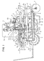
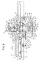
- the transplantation machine includes a main frame 4 frontwardly projecting upper and lower connecting pieces 1 and 2 for connection with a tractor (not shown) and provided driving wheels at rear side, and a movable frame 6 vertically pivotable about a driving shaft 5 transversely extended on the front side of the main frame 4.
- a movable frame 6 On the movable frame 6, rolling coulters 7, 7 for cutting foreign matter, openers 8, 8 for forming ridge grooves, seedling planting wheels 9, 9 for planting seedlings P in the ridge grooves and two sets of press down wheels 10, 10 for pressing down the planted seedlings P are arranged in sequential order from the front side to back side of the movable frame.
- a pair of left and right seedling supply units A, A for supplying respective seedling to the seedling planting wheels 9, 9 are also mounted on the movable frame 6.
- the seedling supply unit A is constructed with the preferred embodiment of the seedling pick-up device according to the present invention for picking up seedlings P from the seedling tray T, a tray transporting device V transporting the seedling tray T toward the seedling pick-up device B, and a transplantation unit E for transferring the seedling P picked up from the seedling pick-up device B to an outfeeding conveyer D.
- the seedling supply unit A constructed set forth above is integrally mounted on the movable frame 6 and a machine frame 11 vertically extending on the front side of the movable frame.
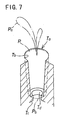
- the seedling tray T is formed by arranging a plurality of cylindrical hole shaped seedling storage cells (hereinafter simply referred to as "cell”) Ta, ... in a tray body of foamed styrol, in a lattice like array with a predetermined pitch ⁇ in back and forth and left and right directions.
- Each cell Ta is formed with gradually reducing diameter from the upper surface opening Tb to a bottom portion Tc.
- a rod insertion hole Td is formed (Figs. 5 to 7 ) .
- the given pitch ⁇ is also provided between a front end face Te of the seedling tray T and a first row of the cells (in the same direction as a transporting direction ⁇ of the seedling tray).
- Such seedling tray T is horizontally mounted on the tray transporting device C in the upright position in each cell Ta in a condition positioning a leaf portion Pa of the seedling P upside.
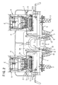
- the tray transporting device C is constructed with a tray transporting drive portion F suspended in the lower portion of the center of a pair of laterally elongated side plates 12 and 13 and a tray transporting conveyer G driven by tray transporting drive portion F (Figs. 1 and 3).
- a construction of the tray transporting conveyer G is as follow.
- a tray transporting belt 16 is stretched on two belt stretching rollers 14 and 15 which are located at the rear end portion and an intermediate portion of the side plates. Between both belt stretching rollers 14 and 15, a belt holding plate 17 is arranged for holding an upper traveling portion 16a so that the upper traveling portion 16a of the tray transporting belt 16 forms a flat surface.
- a gear 19 is mounted via an electromagnetic clutch 18 (Figs. 4 and 5) permitting rotation in one direction, namely only movement of the upper traveling portion 16a of the tray transporting conveyer 16 in the direction of the downstream side in the transporting direction ⁇ of the seedling tray T. Via the electromagnetic clutch 18 and the gear 19, a driving force from the tray transporting drive portion F which will be discussed later, is transmitted to the belt stretching roller 15 (Fig. 5).
- a pair of tray supporting plates 20, 20 for supporting the seedling tray T transferred from the tray transporting conveyer G are arranged to be substantially flush with transverse members 20a, 20a extending laterally between the side plates 12 and 13 and the upper traveling portion 16a of the tray transporting belt 16 by a bracket (not shown) fixed to the transverse members 29a, 20a.
- tray retaining rollers 21, 21 which restrict lifting of the seedling tray T transported thereto, are provided on both sides across the transporting path of the seedling tray T.
- transverse members 22, 22 are extended therebetween.
- a link support shaft 25 is mounted via brackets 26, 26 arranged on both ends thereof.
- a snagglettoothed gear 23 meshing with the gear 19 is fixed at one end.
- suspension links 24, 24 arranged at both end portions the side plate support shaft 29 is suspended.
- a bracket 32 is rigidly secured.
- a drive rod 34 of a fluid pressure cylinder 33 such as pneumatic cylinder, hydraulic cylinder and so forth, is provided.
- a bracket 36 is rigidly secured at the center portion of a transverse member 35 extending transversely between the laterally extending side walls 12 and 13 located at lower portion of the tray transporting conveyer G.
- a bracket 36 is rigidly secured at the center portion of a transverse member 35 extending transversely between the laterally extending side walls 12 and 13 located at lower portion of the tray transporting conveyer G.
- a bracket 36 is rigidly secured.
- a cylinder body 37 of the fluid pressure cylinder 33 is mounted on the bracket 36.
- the snagglettoothed gear 23 is rotated within a predetermined angular range about the link support shaft 25. Associating with this, the belt stretching roller 15 is rotated intermittently in one direction via the gear 19 and the electromagnetic clutch 18.
- the tray transporting belt 16 intermittently drives the upper traveling portion 16a to travel with an internal of the arrangement pitch ⁇ of the cells Ta of the seedling tray T in the transporting direction ⁇ .
- the movable side plates 31, 31 also swing in back and forth direction.
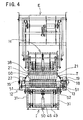
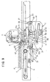
- the seedling pick-up device B includes a seedling holding mechanism H for moving a seedling holding needle 38 which pierces and holds the seedling P, in vertical direction and the seedling pushing mechanism I which pushes up the seedling P stored in the cell Ta of the seedling tray T (Figs. 1, 3, 8).
- the seedling pushing mechanism I is constituted of two link mechanisms which are constructed as follows.
- a connecting member 44 is extended.
- a drive rod 47 of a fluid pressure cylinder 46 such as a hydraulic cylinder, is mounted via a bracket 45 which is provided at the center portion of the connecting member 44.
- a cylinder body 48 is pivotably supported by a bracket 50 provided at the center portion of a connecting member 49 extending transversely on the lower end portion at the center of the movable side plates 31, 31 (Figs . 3, 5, 8).
- the tray positioning rod 51 is formed to have cone-shaped tip end portion 51a, and an intermediate portion 51b following the tip end portion 51a is formed to have an external diameter matching with an internal diameter of rod insertion holes Td.
- the base end portion 51c is formed into cylindrical shape formed to have greater diameter than the rod insertion hole Td.
- the position error of the seedling tray T can be corrected to position the seedling tray T associating with insertion of the tray positioning rod 51 into the tray insertion hole Td.
- the seedling tray T can be accurately positioned.
- the tray positioning rods 51, 51 can be placed at a tray positioning position (b) and a stand-by position (c). Namely, by expansion and compression stroke of the drive rod 47 of the fluid pressure cylinder 46, the vertical lines 41, 41 are moved vertically via swing links 42, 42, 43, 43. Thus, the tray positioning rods 51, 51 are inserted into the cells Ta of the seedling tray T for reciprocally moving between the tray positioning position (b) for positioning the seedling tray T, and the stand-up position (c), in which the tray positioning rods 51, 51 move below the seedling tray.
- a connecting member 55 is extended transversely.
- a bracket 56 rigidly secured at the center of the connecting member 55, a drive rod 58 of a fluid pressure cylinder 57 is mounted on a bracket 56 rigidly secured at the center of the connecting member 55.
- the cylinder body 59 of the fluid pressure cylinder 57 is pivotably connected to a bracket 50 provided at the lower end portion at the center of the movable side plates 31, 31.
- a push rod support member 61 is extended transversely, on which seedling push rods 60 ... for pushing the seedlings P stored in the cells Ta arranged in rows in the seedling tray T, are extended vertically.
- the seedling pushing rods 60 ... are arranged in a distance equal to an arrangement pitch ⁇ of the cell Ta of the seedling tray T, on the upstream side of the transporting direction ⁇ of the seedling tray T from the tray positioning rod 51 (Figs. 1, 3, 8).
- Each seedling pushing rod 60 is a round-bas member having a thickness to be inserted into the rod insertion hole Td of the cell Ta of the seedling tray T.
- the seedling pushing rods 60 corresponding to respective cells Ta ... forming the row of the cells are arranged in the same number as that of the cells Ta ... in equal pitch ⁇ .
- the vertical links 52, 52 are moved vertically via the swing links 53, 53, 54, 54.
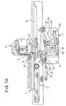
- the seedling contact surface of the seedling pushing rods 60 can be moved reciprocally between a pushing completion position (d) pushing the seedling contact surface to project upper side beyond the upper surface of the seedling tray and a pushing stand-by position (e) placing the seedling contact surface below the seedling tray T (Figs. 9 and 10).
- tray detection sensors 62, 62 for detecting the seedling tray T transported toward the tray positioning rod 51 are arranged.
- the seedling pushing rods 60 ... are driven to elevate upwardly by detecting the seedling tray T by the tray detection sensors 61, 62.
- the seedling tray T mounted on the tray transporting conveyer G are intermittently transported toward downstream side in the transporting direction ⁇ associating with expansion and compression stroke of the drive rod 34 of the fluid pressure cylinder 33 (Fig. 8).
- the tray positioning rod 51 is moved to the tray positioning position (b).
- the seedling pushing rod 60 is moved to the pushing stand-by position (e).
- the drive rod 34 of the fluid pressure cylinder 33 By several times of expansion and compression strokes of the drive rod 34 of the fluid pressure cylinder 33, the front end face Te of the seedling tray T comes into contact with the intermediate portion 51b of the tray positioning rod 51. On the other hand, at a position where the seedling pushing rod 60 matches with the seedling pick-up position (a), the drive cylinder 34 of the fluid pressure cylinder stops at expanded condition.
- the cells Ta ... forming the first row in the seedling tray T is moved to the seedling pick-up position (a).
- This condition is detected by the tray detection sensors 62, 62.
- the seedling pushing rod 60 ... are elevated upwardly to be inserted into respective cells Ta ... forming the first row.
- the seedling P stored in respective cells Ta are pushed up to be picked up (Fig. 9).
- the stand-by position of the tray positioning rod 51 (c) is driven to be lowered.
- the driving rod 34 of the fluid pressure cylinder 33 is contractingly driven.
- the tray positioning rod 51 is moved to the seedling pick-up position (a).
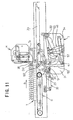
- the seedling pushing rod 60 is placed in opposition to the second row of the cells of the seedling tray T (Fig. 11).
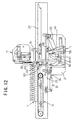
- the tray positioning rod 51 is moved upwardly to the tray positioning position (b) to be inserted into the cells Ta, Ta respectively located at the both ends of the first row of cells in the seedling tray T (Fig. 12). By this, the seedling tray T can be positioned by the tray positioning rod 51.
- the seedling tray T can be shifted for the arrangement pitch ⁇ of the cells Ta toward downstream side in the transporting direction ⁇ of the seedling tray T in the condition where the tray position rods 51 are inserted into the cells Ta, Ta in the first row of the cells. Then, the second row of cells Ta ... are moved to the seedling pick-up position (a) (Fig. 13).
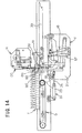
- the tray positioning rod 51 is moved to the pushing completed position (d) by driving the seedling push rods 60 ... upwardly, in the condition where the tray positioning rods 51 are maintained in the condition inserted into the cells Ta, Ta of both ends of the first row of the cells of the seedling tray T to push up the seedlings P stored in the cells Ta ... in the second row (Fig. 14).
- the seedling pushing rods 60 ... can be inserted into the cells in the Nth row of the seedling tray T for picking up the seedlings P. Subsequently, the tray positioning rods 51, 51 are moved for the arrangement pitch of the seedling storage cells Ta toward the downstream side in the transporting direction ⁇ of the seedling tray. Subsequently, the seedling pushing rod 60 is inserted into the cells Ta in the (N+1)th row. Thus, the seedlings P stored in the first row to subsequent rows are picked up in sequential order.
- the seedling holding mechanism H is supported the seedling holding needles 38 which are inserted into the cells Ta forming respective rows moved into the seedling pick-up position (a) for reciprocal movement between the seedling piercing position (f) placing the seedling holding needles in the closest position to the upper opening Tb of the cells Ta and a seedling release position (g) above the transporting conveyer for transferring the seedling P to the transporting conveyer D.
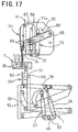
- the construction will be discussed for the case where the seedling holding mechanism H is shifted to the seedling piercing position (f) (Figs. 15, 16).
- a needle supporting member 64 On the read end portion side of a pair of side plates 63, 63, a needle supporting member 64, on which a plurality of seedling holding needles 38 ... are vertically provided in alignment on the tip end portion and a guide plate 67 formed with guide grooves 66 guiding the rollers 65, 65 arranged on both sides of the needle supporting member 64.
- the needle supporting member 64 is pivoted between the free end portions of swing arms 69, 69 pivoted the base end portion about a shaft extending between the front end portions of the left and right side plates 63, 63.
- a fluid pressure cylinder 73 utilizing fluid pressure, such as pneumatic pressure, hydraulic pressure or so forth, is disposed (Figs. 15 to 17).
- the fluid pressure cylinder 73 is adapted to be driven in synchronism with the seedling pushing mechanism I by detecting the seedling tray T by the tray detecting sensor 62.
- the seedling holding needle 38 is straight.
- the seedling holding needles 38 are arranged in alignment along the direction of the row of the cells with a pitch corresponding to the pitch ⁇ between the cells Ta of the seedling tray T, each two needles for each cell.
- the seedling release plate 74 on which needle loosely insertion holes (not shown), loosely receiving respective seedling holding needles 38 are provided in alignment, are provided.
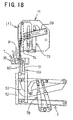
- a drive rod 73a of the fluid pressure cylinder 73 is driven for compression to downwardly drive the seedling holding needles 38 to pierce the seedlings P stored in the cells Ta ...
- the seedling pushing rods 60 are moved upwardly to contact the seeding contact faces with the bottom surface of the seedlings P within the cells Ta.
- the seedling holding needles 38 are driven upwardly at the same speed as that of the seedling pushing rods 60 (Fig. 18).
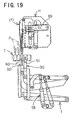
- the seedlings P are maintained in the position pierced by the seedling holding needles 38, and is moved to the pushing completed position (d) (Fig, 19) in the condition supported from the lower side by the seedling pushing rods 60 for preventing loosing off.
- the construction of the transfer device E is as follow.
- a connection pipe 76 is transversely extended between the upper end portions of a pair of left and right side plates 75, 75. Between support legs 77 to 79 vertically extended from the side plates 75, 75, support shafts 81 fixed brackets 80, 80 at both ends thereof, are rotatably extended thereacross. On the other hand, between the support legs 77 and 78, a motor M is fixed. In conjunction therewith, a rotary shaft 84, on which a drive gear 83 meshes with a gear 82 fixed to a drive shaft of the motor M, is fixed at the inner end portion.
- the pivotal arms 87 and 87 are pivoted for shifting the seedling holding mechanism H between the seedling piecing position (f) and the seedling release position (g).
- a small gear 91 meshing with the drive gear 83 is fixed. Also, on the brackets 80, 80 provided on both ends of the support shaft 81, the upper end portion of support arms 93, 93 pivoting the side plates 63, 63 of the seedling holding mechanism H, are mounted via a shaft 92 which is provided between the lower end portions between the brackets 80, 80.
- the eccentric shaft 83a is moved from the drive starting position (h) to the drive terminating position (i) to cause upward pivotal movement of the brackets 80, 80.
- a force for upwardly pivoting about the shaft 86 of the pivotal arms 87, 87 acts on the side plates 63, 63 of the seedling holding mechanism H.
- the seedling holding mechanism H is upwardly pivoted over 90° about the shaft 86 so that the seedling holding needles 38 is oriented in substantially horizontal direction. With maintaining this attitude, the seedling holding mechanism H is moved to the seedling release position (g).
- the seedling holding mechanism H is returned from the seedling release position (g) to the seedling piercing direction (f) through the reversed path.
- the transporting conveyer D is supported about a tray space SP defined on the front end portion of a pair of left and right side plates 12 and 13, at the upper end portion of the machine frame 11.
- a vertical conveyer 94 transporting the seedling P toward seedling planting rings 9, 9, is provided (Fig. 1).
- the seedling pushing rod 600 is returned to the pushing stand-by position (e).
- the seedling holding mechanism H is shifted from the seedling piercing position (f) to the seedling release position (g). During this, the seedling holding mechanism H is pivoted over 90° about the shaft 86.
- the fluid pressure cylinder 73 of the seedling holding mechanism H is driven to expand the drive rod to abruptly retract the seedling holding needle 38 between the side plates 63, 63.
- each seedling P pierced by the seedling holding needle 38 is released by the seedling release plate 74.
- the seedling is released on the outfeeding conveyer D located at the lower position.
- the seedling P released on the outfeeding conveyer D is subsequently transferred to the vertical conveyer 94 and transported toward the seedling planting ring 9.
- the seedling holding mechanism H In conjunction with releasing of the seedling P, the seedling holding mechanism H is moved to return to the seedling piercing position (f), and the seedling pushing rod 60 of the seedling pushing mechanism I is returned to the pushing stand-by position (e). Then, the seedling tray T is intermittently transported to place the next row of the cells at the seedling pick-up position (a).
- the tray positioning rod is inserted into a part of the seedling storage cells in the row or rows other than the row of the cells, to which the seedling pushing rods are about inserted.
- the positioning may be done in the following manner.
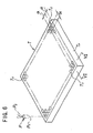
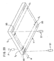
- a seedling tray T' shown in Fig. 20 is formed with a plurality of positioning rod insertion holes 95 ... in both side portions of the bottom surface. In parallel to the transporting direction ⁇ of the seedling tray T' and with an interval consistent with the arrangement pitch ⁇ of the cells Ta ... , the positioning rod insertion holes 95 ... are aligned.
- the positioning rod insertion hole 95 may be the same shape as the cell Ta, or, in the alternative, the positioning rod insertion hole 95 may be formed in recessed manner in the bottom surface so that it may not be seen from the upper surface of the seedling tray T'.
- a plurality of positioning rod insertion holes 95 ... are formed in both side portions of the bottom surface of the seedling tray T' in parallel to the transporting direction ⁇ of the seedling tray T' and in alignment in a pitch corresponding to the arrangement pitch ⁇ of the cells Ta ..., the arranging position of the tray positioning rods 51, 51 of the seedling pushing mechanism I, the seedling tray T' can be transported only by arranging pairs of left and right rod insertion holes 95, 95 at an interval for placing the rod insertion holes in opposition to the tray positioning rods 51, 51.
- a plurality of positioning rod insertion holes 95 ... is not limited to those formed in the pitch corresponding to the arrangement pitch ⁇ of the cells Ta ... but can be any necessary interval. In this case, by setting the interval of the positioning rod insertion holes in 1/n (n is integer) of the arrangement pitch ⁇ of the cells Ta ..., the seedling tray T' can be easily transported.
- tray positioning rods are inserted into two cells in the same row
- the present invention should not be limited to the shown construction. It is possible to position the seedling tray by inserting two tray positioning rods into the cells in different rows. Furthermore, number of the tray positioning rods is not specified to two but can be three or more for positioning the seedling tray.
Landscapes
- Life Sciences & Earth Sciences (AREA)
- Environmental Sciences (AREA)
- Soil Sciences (AREA)
- Cultivation Receptacles Or Flower-Pots, Or Pots For Seedlings (AREA)
- Transplanting Machines (AREA)
- Pretreatment Of Seeds And Plants (AREA)
- Hydroponics (AREA)
Claims (17)
- Verfahren zum Aufnehmen von Sämlingen (P) aus einer Sämlingsstiege (T; T') durch Einfügen von Sämlings-Stoßstäben (60) in Stab-Einfügelöcher (Td), die in Böden (Tc) von jeweiligen Sämlings-Lagerungszellen (Ta) ausgebildet sind, die in Zeilen ausgebildet sind und die in Ausrichtung mit einer vorbestimmten Teilung (α) in der Sämlingsstiege (T; T') ausgebildet sind, die in einer Richtung (β) transportiert wird, wobei die Sämlings-Stoßstäbe (60) entsprechend den Sämlings-Lagerungszellen (Ta) in einer Zeile und in Ausrichtung mit der vorbestimmten Teilung (α) angeordnet sind, wobei das Verfahren die folgenden Schritte aufweist:Positionieren der Sämlingsstiege (T; T') bei einer vorbestimmten Position mittels Stiegen-Positionierstäben (51), die die Sämlingsstiege (T; T') durch Bewegen der Sämlingsstiege (T; T') in einer Richtung senkrecht zu der einen Richtung (β) und Einfügen der Stiegen-Positionierstäbe (51 ) in einige der Stab-Einfügelöcher (Td) und/oder in einige Stiegen-Positionierlöcher (95), die in beiden Seitenteilen der unteren Oberfläche der Sämlingsstiege (T') ausgebildet sind, wobei die Stiegen-Positionierlöcher (95) parallel zu der einen Richtung (β) der Sämlingsstiege (T') ausgerichtet und mit einem vorbestimmten Intervall zueinander sind; undEinfügen der Sämlings-Stoßstäbe (60) in die Stab-Einfügelöcher (Td), in welche die Stiegen-Positionierstäbe (51) nicht eingefügt sind, während die Sämlingsstiege (T; T') in einem positionierten Zustand beibehalten wird.
- Verfahren nach Anspruch 1, wobei die Stiegen-Positionierstäbe (51) in einige Sämlings-Lagerungszellen (Ta) eingefügt werden, die in einer Zeile angeordnet sind, und die Sämlings-Stoßstäbe (60) in einige Sämlings-Lagerungszellen (Ta) eingefügt werden, die in einer anderen Zeile angeordnet sind.
- Verfahren nach Anspruch 2, wobei die eine Zeile und die andere Zeile jeweils die N-te Zeile und die (N+1)-te Zeile sind.
- Verfahren nach einem der vorangehenden Ansprüche, wobei die Stiegen-Positionierstäbe (51) während eines Positionierens der Sämlingsstiegen (T; T') unter Beibehaltung des Zustands, in welchem die Stiegen-Positionierstäbe (51 ) in die Sämlings-Lagerungszellen (Ta) eingefügt sind um ein Ausmaß entsprechend der vorbestimmten Teilung (α) in einer Transportrichtung der Sämlingsstiegen (T; T') stromabwärts bewegt werden.
- Verfahren nach einem der vorangehenden Ansprüche, wobei die Sämlingsstiegen (T; T') durch Anlegen der Stiegen-Positionierstäbe (51) an eine vordere Endfläche der Sämlingsstiege (T; T') positioniert werden.
- Verfahren nach einem der vorangehenden Ansprüche, wobei das vorbestimmte Intervall zwischen den Stiegen-Positionierlöchem (95) mit der vorbestimmten Teilung (α) der Sämlings-Lagerungszellen (Ta) übereinstimmt oder derart eingestellt wird, dass es 1/n, wobei n eine ganze Zahl ist, der vorbestimmten Teilung (α) der Sämlings-Lagerungszellen (Ta) ist.
- Verfahren nach einem der vorangehenden Ansprüche, wobei Sämlings-Haltenadeln (38) in die Sämlings-Lagerungszellen (Ta) von einer oberen Oberfläche, die sich von dort öffnet, aus nach unten geschoben werden, um die in den Sämlings-Lagerungszellen (Ta) gelagerten Sämlinge (P) durch die Sämlings-Haltenadeln (38) zu durchdringen und zu halten, und dann die Sämlings-Stoßstäbe (60) nach oben angehoben werden, um an der unteren Oberfläche der durch die Sämlings-Haltenadeln (38) durchdrungenen und gehaltenen Sämlinge (P) zum Stoßen der Sämlinge (P) durch Anheben der Sämlings-Haltenadeln (38) und der Sämlings-Stoßstäbe (60) mit derselben Geschwindigkeit nach oben unter Druck anzuliegen.
- Vorrichtung zum Aufnehmen von Sämlingen (P) aus einer zugehörigen Sämlingsstiege (T; T'), wobei die Sämlinge (P) pro jeweiliger Zeile von Lagerungszellen (Ta) aufgenommen werden, die in Zeilen ausgebildet sind und die in Ausrichtung mit einer vorbestimmten Teilung (α) in der Sämlingsstiege (T; T') ausgebildet sind, die in einer Richtung (β) transportiert wird, wobei die Vorrichtung folgendes aufweist:Stiegen-Positionierstäbe (51 ), um, eingefügt in einige von Stab-Einfügelöchern (Td), die in Böden (Tc) von jeweiligen Sämlings-Lagerungszellen (Ta) ausgebildet sind, und/oder in einige von Stiegen-Positionierlöchern (95), die in beiden Seitenteilen der unteren Oberfläche der Sämlingsstiege (T') ausgebildet sind, in einer Richtung senkrecht zu der einen Richtung (β) der Sämlingsstiege (T; T') bewegt zu werden, wobei die Stiegen-Positionierlöcher (95) parallel zu der einen Richtung (β) der Sämlingsstiege (T') ausgerichtet und mit einem vorbestimmten Intervall zueinander sind, und im eingefügten Zustand zusammen mit der Sämlingsstiege (T; T') zu einer vorbestimmten Position bewegt werden; undSämlings-Stoßstäbe (60), die entsprechend den Sämlings-Lagerungszellen (Ta) in einer Zeile und in Ausrichtung mit der vorbestimmten Teilung (α) angeordnet sind und eine Einfügeoperation in die Stab-Einfügelöcher (Td) durchführen, in welche die Stiegen-Positionierstäbe (51) nicht eingefügt sind, während ein Zustand beibehalten wird, in welchem die Sämlingsstiege (T; T) bei der vorbestimmten Position positioniert ist.
- Vorrichtung nach Anspruch 8, wobei die Stiegen-Positionierstäbe (51 ) angeordnet sind, um in einige Sämlings-Lagerungszellen (Ta) eingefügt zu werden, die in einer Zeile angeordnet sind, und die Sämlings-Stoßstäbe (60) angeordnet sind, um in einige Sämlings-Lagerungszellen (Ta) eingefügt zu werden, die in einer anderen Zeile angeordnet sind.
- Vorrichtung nach Anspruch 9, wobei die eine Zeile und die andere Zeile jeweils die N-te Zeile und die (N+1 )-te Zeile sind.
- Vorrichtung nach einem der Ansprüche 8 bis 10, die weiterhin eine Stiegen-Positioniervorrichtung (C) aufweist, die die Sämlingsstiege (T; T') während eines Positionierens der Sämlingsstiegen (T; T) unter Beibehaltung des Zustands, in welchem die Stiegen-Positionierstäbe (51) in die Sämlings-Lagerungszellen (Ta) eingefügt sind, durch Verschieben der Stiegen-Positionierstäbe (51) um ein Ausmaß entsprechend der vorbestimmten Teilung (α) in einer Transportrichtung der Sämlingsstiegen (T; T') stromabwärts intermittierend transportiert.
- Vorrichtung nach einem der Ansprüche 8 bis 11, wobei die Stiegen-Positionierstäbe (51 ) und die Stiegen-Stoßstäbe (60) mit einem Intervall entsprechend der vorbestimmten Teilung (α) der Sämlings-Lagerungszellen (Ta) zueinander angeordnet sind.
- Vorrichtung nach einem der Ansprüche 8 bis 12, wobei die Stiegen-Positionierstäbe (51) und die Stiegen-Stoßstäbe (60) angeordnet sind, um unter Beibehaltung eines konstanten Intervalls in der einen Richtung (β) gleichzeitig verschoben zu werden und um in der Richtung senkrecht zu der einen Richtung (β) unabhängig voneinander verschoben zu werden.
- Vorrichtung nach einem der Ansprüche 12 oder 13, die weiterhin folgendes aufweist: zwei Verbindungsmechanismen, die die Stiegen-Positionierstäbe (51) und die Sämlings-Stoßstäbe (60) auf bewegliche Weise unabhängig voneinander in der Richtung senkrecht zu der einen Richtung (β) stützen, einen Sämlings-Stoßmechanismus (I), der in jedem Verbindungsmechanismus vorgesehen ist und aus einem FluidDruckzylinder aufgebaut ist, und einen Stiegen-Transportantriebsteil (F), der den Sämlings-Stoßmechanismus mit demselben Hub wie der vorbestimmten Teilung (α) in der einen Richtung (β) hin- und herbewegend verschiebt.
- Vorrichtung nach einem der Ansprüche 8 bis 14, wobei die Stiegen-Positionierstäbe (51 ) bei Positionen gegenüberliegend zu den Sämlings-Lagerungszellen (Ta) angeordnet sind, die an der äußersten Seite der Sämlings-Lagerungszellen (Ta) in einer Zeile angeordnet sind.
- Vorrichtung nach einem der Ansprüche 8 bis 15, wobei das vorbestimmte Intervall zwischen den Stiegen-Positionierlöchern (95) mit der vorbestimmten Teilung (α) der Sämlings-Lagerungszellen (Ta) übereinstimmt oder derart eingestellt ist, dass es 1/n, wobei n eine ganze Zahl ist, der vorbestimmten Teilung (α) der Sämlings-Lagerungszellen (Ta) ist.
- Vorrichtung nach einem der Ansprüche 8 bis 16, wobei die Stiegen-Positionierstab (51) einen äußersten Endabschnitt hat, der in einer konusförmigen Konfiguration ausgebildet ist, und einen dem äußersten Endabschnitt folgenden mittleren Abschnitt, welcher mittlere Abschnitt einen Außendurchmesser hat, der mit einem Innendurchmesser des Stab-Einfügelochs (Td) und/oder des Stiegen-Positionierlochs (95) übereinstimmt.
Applications Claiming Priority (3)
| Application Number | Priority Date | Filing Date | Title |
|---|---|---|---|
| JP25792797 | 1997-09-08 | ||
| JP257927/97 | 1997-09-08 | ||
| JP25792797A JP3849084B2 (ja) | 1997-09-08 | 1997-09-08 | 苗株トレイからの苗株取出し方法とその装置 |
Publications (2)
| Publication Number | Publication Date |
|---|---|
| EP0900516A1 EP0900516A1 (de) | 1999-03-10 |
| EP0900516B1 true EP0900516B1 (de) | 2003-11-19 |
Family
ID=17313136
Family Applications (1)
| Application Number | Title | Priority Date | Filing Date |
|---|---|---|---|
| EP98101478A Expired - Lifetime EP0900516B1 (de) | 1997-09-08 | 1998-01-28 | Verfahren und Einrichtung zur Aufnahme von Sämlingen aus einer Sämlingschale |
Country Status (10)
| Country | Link |
|---|---|
| US (1) | US6044778A (de) |
| EP (1) | EP0900516B1 (de) |
| JP (1) | JP3849084B2 (de) |
| AT (1) | ATE254390T1 (de) |
| AU (1) | AU731084B2 (de) |
| CA (1) | CA2246394C (de) |
| DE (1) | DE69819829T2 (de) |
| DK (1) | DK0900516T3 (de) |
| ES (1) | ES2212151T3 (de) |
| PT (1) | PT900516E (de) |
Families Citing this family (25)
| Publication number | Priority date | Publication date | Assignee | Title |
|---|---|---|---|---|
| ES1044131Y (es) * | 1999-08-19 | 2000-08-16 | Semirec S L | Transplantadora automatica de hortalizas. |
| US7984583B2 (en) * | 2001-01-24 | 2011-07-26 | Tagawa Greenhouse Enterprises, Llc | Plant punch methods and apparatus |
| US20040118730A1 (en) * | 2002-11-05 | 2004-06-24 | Rynel, Inc. | Trays for growth plugs, and methods of producing them |
| US20060130720A1 (en) | 2003-05-01 | 2006-06-22 | Bart Parrein | Method and apparatus for transporting seedlings in a planting machine |
| US20050220580A1 (en) * | 2004-03-15 | 2005-10-06 | Thomas Arnold | Dual mode stacking system and method of use |
| CN103181259B (zh) * | 2013-03-29 | 2015-04-22 | 罗忠良 | 一种水稻自动抛秧装置 |
| CN103190307B (zh) * | 2013-04-24 | 2014-12-03 | 东北农业大学 | 育秧大棚自动摆盘装置 |
| JP5939211B2 (ja) * | 2013-07-02 | 2016-06-22 | 井関農機株式会社 | 移植機 |
| KR101654088B1 (ko) * | 2013-05-31 | 2016-09-05 | 이세키노우키가부시키가이샤 | 이식기 |
| TWI566683B (zh) * | 2014-07-17 | 2017-01-21 | An automatic seedling transplanting facility | |
| FI125975B (fi) | 2014-10-31 | 2016-05-13 | Risutec Oy | Menetelmä taimien istutuskoneessa ja taimien istutuskone |
| WO2016195604A1 (en) * | 2015-06-03 | 2016-12-08 | Kasetsart University | An apparatus for transferring seedlings or plant propagation materials and process thereof |
| USD783421S1 (en) | 2016-01-05 | 2017-04-11 | Van Belle Nursery Inc. | Seedling tray |
| CN112889412B (zh) * | 2021-03-11 | 2024-10-22 | 陆川县永成家庭农场 | 一种水稻播种机 |
| CN113079774B (zh) * | 2021-04-27 | 2022-02-15 | 江苏大学 | 一种自动移栽机用苗盘输送定位装置及输送投苗方法 |
| CN113711746B (zh) * | 2021-10-18 | 2022-10-21 | 无锡悦田农业机械科技有限公司 | 一种穴盘苗自动移栽机顶苗装置 |
| CN114830893B (zh) * | 2022-04-25 | 2025-07-25 | 湖南农业大学 | 一种钵苗取输苗装置 |
| CN115176567B (zh) * | 2022-05-16 | 2023-09-05 | 贵州理工学院 | 一种抛秧无人机 |
| CN115880688B (zh) * | 2022-12-08 | 2025-12-19 | 西北农林科技大学 | 一种酿酒葡萄副芽定位与抹除方法 |
| TWI810128B (zh) * | 2022-12-21 | 2023-07-21 | 國立中興大學 | 氣壓式穴盤之自動化播種裝置 |
| GB2629044A (en) * | 2023-02-22 | 2024-10-16 | Univ Jiangsu | Self-propelled full-automatic densely-planting vegetable transplanter and planting control method thereof |
| CN116438985B (zh) * | 2023-04-21 | 2025-06-20 | 江西农业大学 | 一种凸轮周转连续并行顶出式取苗装置 |
| CN117378333B (zh) * | 2023-11-07 | 2024-06-04 | 河北热点农业发展有限公司 | 基于智慧农业的自动化分苗机 |
| CN118266307B (zh) * | 2024-06-04 | 2024-08-06 | 云南珍竹农业科技有限公司 | 用于竹子种植的辅助直立设备 |
| CN121153515B (zh) * | 2025-11-03 | 2026-04-14 | 中国热带农业科学院农业机械研究所 | 一种立体育苗设施 |
Family Cites Families (8)
| Publication number | Priority date | Publication date | Assignee | Title |
|---|---|---|---|---|
| JPS6094023U (ja) * | 1983-07-29 | 1985-06-27 | 株式会社サークル鉄工 | 移植機の紙筒苗選別搬送装置 |
| FR2658980B1 (fr) * | 1990-03-02 | 1992-07-10 | Claire Fontaine Ateliers | Perfectionnement aux machines a repiquer des plants en mottes et porte-plateau interface adapte a ces machines. |
| ATE193411T1 (de) * | 1992-08-10 | 2000-06-15 | Williames Hi Tech Int | Automatische pflanzmaschine topfballen aus einer saatkiste nehmend |
| EP0712271A4 (de) * | 1993-08-04 | 1996-10-23 | Speedling Inc | Pflanzmaschine für topfballen |
| JPH07184421A (ja) * | 1993-12-28 | 1995-07-25 | Yanmar Agricult Equip Co Ltd | 移植機のトレイ縦送り装置 |
| US5860372A (en) * | 1995-02-21 | 1999-01-19 | Bouldin & Lawson, Inc. | Seedling transplanter with planting fingers |
| US5596938A (en) * | 1995-06-07 | 1997-01-28 | Shaw; Lawrance N. | Apparatus for unloading seedlings from a tray and transporting them elsewhere |
| JP3215941B2 (ja) * | 1996-05-10 | 2001-10-09 | 株式会社サークル鉄工 | 苗株搬送装置とその搬送方法 |
-
1997
- 1997-09-08 JP JP25792797A patent/JP3849084B2/ja not_active Expired - Fee Related
-
1998
- 1998-01-14 US US09/006,882 patent/US6044778A/en not_active Expired - Fee Related
- 1998-01-28 DK DK98101478T patent/DK0900516T3/da active
- 1998-01-28 ES ES98101478T patent/ES2212151T3/es not_active Expired - Lifetime
- 1998-01-28 AT AT98101478T patent/ATE254390T1/de not_active IP Right Cessation
- 1998-01-28 DE DE69819829T patent/DE69819829T2/de not_active Expired - Fee Related
- 1998-01-28 EP EP98101478A patent/EP0900516B1/de not_active Expired - Lifetime
- 1998-01-28 PT PT98101478T patent/PT900516E/pt unknown
- 1998-09-02 CA CA002246394A patent/CA2246394C/en not_active Expired - Fee Related
- 1998-09-07 AU AU83165/98A patent/AU731084B2/en not_active Ceased
Also Published As
| Publication number | Publication date |
|---|---|
| US6044778A (en) | 2000-04-04 |
| DK0900516T3 (da) | 2004-03-29 |
| CA2246394A1 (en) | 1999-03-08 |
| DE69819829T2 (de) | 2004-09-23 |
| JP3849084B2 (ja) | 2006-11-22 |
| ES2212151T3 (es) | 2004-07-16 |
| ATE254390T1 (de) | 2003-12-15 |
| AU8316598A (en) | 1999-03-18 |
| JPH1175436A (ja) | 1999-03-23 |
| CA2246394C (en) | 2003-08-05 |
| EP0900516A1 (de) | 1999-03-10 |
| PT900516E (pt) | 2004-04-30 |
| DE69819829D1 (de) | 2003-12-24 |
| AU731084B2 (en) | 2001-03-22 |
Similar Documents
| Publication | Publication Date | Title |
|---|---|---|
| EP0900516B1 (de) | Verfahren und Einrichtung zur Aufnahme von Sämlingen aus einer Sämlingschale | |
| US9408398B2 (en) | Apparatus for aligning and positioning pieces of food dough | |
| JP3872549B2 (ja) | ピックアップ装置 | |
| JP3215941B2 (ja) | 苗株搬送装置とその搬送方法 | |
| JPH08504709A (ja) | 物品をプラスチック製袋の壁に取付ける装置及び方法 | |
| JPH04367417A (ja) | 包装機への物品の自動整列供給方法と装置 | |
| KR101220279B1 (ko) | 진단키트의 생산시스템 | |
| CN106856757A (zh) | 一种钵苗脱盘装置 | |
| JPH0650321Y2 (ja) | 塊状物の充填装置 | |
| CN208159247U (zh) | 一种钵苗移送装置 | |
| JPH09266707A (ja) | 苗株トレイの搬送方法とその装置 | |
| MXPA98007269A (en) | Method and device for collecting seed plant from a semi plant table | |
| JPH09226934A (ja) | 複数ヘッドのピッチ変更機構 | |
| CN217416257U (zh) | 物料编组装置 | |
| CN216613001U (zh) | 一种物料输出装置 | |
| JPH0379247B2 (de) | ||
| CN224159513U (zh) | 一种营养粥用的定量灌装设备 | |
| JPH10178889A (ja) | きのこ種菌接種機 | |
| JPH09220537A (ja) | 苗判別用センシングコンベア | |
| JPH09266706A (ja) | 苗株取出し方法とその装置 | |
| JP3717296B2 (ja) | 乾麺移載装置 | |
| CN118923303A (zh) | 烟草气控全自动送盘取苗装置 | |
| JPH11318208A (ja) | きのこ種菌接種機 | |
| CN120482602A (zh) | 自动管翅布排设备 | |
| JPS601537Y2 (ja) | 移植機の苗供給装置における駆動構造 |
Legal Events
| Date | Code | Title | Description |
|---|---|---|---|
| PUAI | Public reference made under article 153(3) epc to a published international application that has entered the european phase |
Free format text: ORIGINAL CODE: 0009012 |
|
| AK | Designated contracting states |
Kind code of ref document: A1 Designated state(s): AT BE CH DE DK ES FI FR GB GR IE IT LI LU MC NL PT SE |
|
| AX | Request for extension of the european patent |
Free format text: AL;LT;LV;MK;RO;SI |
|
| 17P | Request for examination filed |
Effective date: 19990823 |
|
| AKX | Designation fees paid |
Free format text: AT BE CH DE DK ES FI FR GB GR IE IT LI LU MC NL PT SE |
|
| 17Q | First examination report despatched |
Effective date: 20010711 |
|
| GRAH | Despatch of communication of intention to grant a patent |
Free format text: ORIGINAL CODE: EPIDOS IGRA |
|
| RTI1 | Title (correction) |
Free format text: METHOD AND DEVICE FOR PICKING UP SEEDLING FROM SEEDLING TRAY |
|
| GRAS | Grant fee paid |
Free format text: ORIGINAL CODE: EPIDOSNIGR3 |
|
| GRAA | (expected) grant |
Free format text: ORIGINAL CODE: 0009210 |
|
| AK | Designated contracting states |
Kind code of ref document: B1 Designated state(s): AT BE CH DE DK ES FI FR GB GR IE IT LI LU MC NL PT SE |
|
| REG | Reference to a national code |
Ref country code: GB Ref legal event code: FG4D |
|
| REG | Reference to a national code |
Ref country code: CH Ref legal event code: EP |
|
| REF | Corresponds to: |
Ref document number: 69819829 Country of ref document: DE Date of ref document: 20031224 Kind code of ref document: P |
|
| REG | Reference to a national code |
Ref country code: IE Ref legal event code: FG4D |
|
| REG | Reference to a national code |
Ref country code: CH Ref legal event code: NV Representative=s name: ROTTMANN, ZIMMERMANN + PARTNER AG |
|
| REG | Reference to a national code |
Ref country code: SE Ref legal event code: TRGR |
|
| REG | Reference to a national code |
Ref country code: GR Ref legal event code: EP Ref document number: 20040400523 Country of ref document: GR |
|
| REG | Reference to a national code |
Ref country code: DK Ref legal event code: T3 |
|
| REG | Reference to a national code |
Ref country code: PT Ref legal event code: SC4A Free format text: AVAILABILITY OF NATIONAL TRANSLATION Effective date: 20040217 |
|
| ET | Fr: translation filed | ||
| REG | Reference to a national code |
Ref country code: ES Ref legal event code: FG2A Ref document number: 2212151 Country of ref document: ES Kind code of ref document: T3 |
|
| PLBE | No opposition filed within time limit |
Free format text: ORIGINAL CODE: 0009261 |
|
| STAA | Information on the status of an ep patent application or granted ep patent |
Free format text: STATUS: NO OPPOSITION FILED WITHIN TIME LIMIT |
|
| 26N | No opposition filed |
Effective date: 20040820 |
|
| PGFP | Annual fee paid to national office [announced via postgrant information from national office to epo] |
Ref country code: FI Payment date: 20060120 Year of fee payment: 9 Ref country code: MC Payment date: 20060120 Year of fee payment: 9 |
|
| PGFP | Annual fee paid to national office [announced via postgrant information from national office to epo] |
Ref country code: SE Payment date: 20060121 Year of fee payment: 9 |
|
| PGFP | Annual fee paid to national office [announced via postgrant information from national office to epo] |
Ref country code: CH Payment date: 20060124 Year of fee payment: 9 Ref country code: GR Payment date: 20060124 Year of fee payment: 9 |
|
| PGFP | Annual fee paid to national office [announced via postgrant information from national office to epo] |
Ref country code: DK Payment date: 20060125 Year of fee payment: 9 |
|
| PGFP | Annual fee paid to national office [announced via postgrant information from national office to epo] |
Ref country code: LU Payment date: 20060203 Year of fee payment: 9 |
|
| PG25 | Lapsed in a contracting state [announced via postgrant information from national office to epo] |
Ref country code: FI Free format text: LAPSE BECAUSE OF NON-PAYMENT OF DUE FEES Effective date: 20070128 |
|
| PG25 | Lapsed in a contracting state [announced via postgrant information from national office to epo] |
Ref country code: SE Free format text: LAPSE BECAUSE OF NON-PAYMENT OF DUE FEES Effective date: 20070129 |
|
| PG25 | Lapsed in a contracting state [announced via postgrant information from national office to epo] |
Ref country code: MC Free format text: LAPSE BECAUSE OF NON-PAYMENT OF DUE FEES Effective date: 20070131 Ref country code: LI Free format text: LAPSE BECAUSE OF NON-PAYMENT OF DUE FEES Effective date: 20070131 Ref country code: CH Free format text: LAPSE BECAUSE OF NON-PAYMENT OF DUE FEES Effective date: 20070131 |
|
| REG | Reference to a national code |
Ref country code: CH Ref legal event code: PL |
|
| EUG | Se: european patent has lapsed | ||
| REG | Reference to a national code |
Ref country code: DK Ref legal event code: EBP |
|
| PG25 | Lapsed in a contracting state [announced via postgrant information from national office to epo] |
Ref country code: DK Free format text: LAPSE BECAUSE OF NON-PAYMENT OF DUE FEES Effective date: 20070131 |
|
| PGFP | Annual fee paid to national office [announced via postgrant information from national office to epo] |
Ref country code: ES Payment date: 20080125 Year of fee payment: 11 |
|
| PGFP | Annual fee paid to national office [announced via postgrant information from national office to epo] |
Ref country code: PT Payment date: 20080115 Year of fee payment: 11 Ref country code: NL Payment date: 20080124 Year of fee payment: 11 Ref country code: IT Payment date: 20080126 Year of fee payment: 11 Ref country code: IE Payment date: 20080129 Year of fee payment: 11 Ref country code: GB Payment date: 20080123 Year of fee payment: 11 Ref country code: DE Payment date: 20080128 Year of fee payment: 11 |
|
| PGFP | Annual fee paid to national office [announced via postgrant information from national office to epo] |
Ref country code: AT Payment date: 20080123 Year of fee payment: 11 |
|
| PGFP | Annual fee paid to national office [announced via postgrant information from national office to epo] |
Ref country code: FR Payment date: 20080118 Year of fee payment: 11 |
|
| PGFP | Annual fee paid to national office [announced via postgrant information from national office to epo] |
Ref country code: BE Payment date: 20080123 Year of fee payment: 11 |
|
| PG25 | Lapsed in a contracting state [announced via postgrant information from national office to epo] |
Ref country code: GR Free format text: LAPSE BECAUSE OF NON-PAYMENT OF DUE FEES Effective date: 20070802 |
|
| REG | Reference to a national code |
Ref country code: PT Ref legal event code: MM4A Free format text: LAPSE DUE TO NON-PAYMENT OF FEES Effective date: 20090728 |
|
| PG25 | Lapsed in a contracting state [announced via postgrant information from national office to epo] |
Ref country code: LU Free format text: LAPSE BECAUSE OF NON-PAYMENT OF DUE FEES Effective date: 20070128 |
|
| GBPC | Gb: european patent ceased through non-payment of renewal fee |
Effective date: 20090128 |
|
| NLV4 | Nl: lapsed or anulled due to non-payment of the annual fee |
Effective date: 20090801 |
|
| REG | Reference to a national code |
Ref country code: IE Ref legal event code: MM4A |
|
| PG25 | Lapsed in a contracting state [announced via postgrant information from national office to epo] |
Ref country code: PT Free format text: LAPSE BECAUSE OF NON-PAYMENT OF DUE FEES Effective date: 20090728 Ref country code: DE Free format text: LAPSE BECAUSE OF NON-PAYMENT OF DUE FEES Effective date: 20090801 Ref country code: AT Free format text: LAPSE BECAUSE OF NON-PAYMENT OF DUE FEES Effective date: 20090128 |
|
| REG | Reference to a national code |
Ref country code: FR Ref legal event code: ST Effective date: 20091030 |
|
| PG25 | Lapsed in a contracting state [announced via postgrant information from national office to epo] |
Ref country code: NL Free format text: LAPSE BECAUSE OF NON-PAYMENT OF DUE FEES Effective date: 20090801 Ref country code: GB Free format text: LAPSE BECAUSE OF NON-PAYMENT OF DUE FEES Effective date: 20090128 |
|
| PG25 | Lapsed in a contracting state [announced via postgrant information from national office to epo] |
Ref country code: IE Free format text: LAPSE BECAUSE OF NON-PAYMENT OF DUE FEES Effective date: 20090128 |
|
| PG25 | Lapsed in a contracting state [announced via postgrant information from national office to epo] |
Ref country code: BE Free format text: LAPSE BECAUSE OF NON-PAYMENT OF DUE FEES Effective date: 20090131 |
|
| REG | Reference to a national code |
Ref country code: ES Ref legal event code: FD2A Effective date: 20090129 |
|
| PG25 | Lapsed in a contracting state [announced via postgrant information from national office to epo] |
Ref country code: FR Free format text: LAPSE BECAUSE OF NON-PAYMENT OF DUE FEES Effective date: 20090202 Ref country code: ES Free format text: LAPSE BECAUSE OF NON-PAYMENT OF DUE FEES Effective date: 20090129 |
|
| PG25 | Lapsed in a contracting state [announced via postgrant information from national office to epo] |
Ref country code: IT Free format text: LAPSE BECAUSE OF NON-PAYMENT OF DUE FEES Effective date: 20090128 |