EP0900516B1 - Method and device for picking up seedling from seedling tray - Google Patents
Method and device for picking up seedling from seedling tray Download PDFInfo
- Publication number
- EP0900516B1 EP0900516B1 EP98101478A EP98101478A EP0900516B1 EP 0900516 B1 EP0900516 B1 EP 0900516B1 EP 98101478 A EP98101478 A EP 98101478A EP 98101478 A EP98101478 A EP 98101478A EP 0900516 B1 EP0900516 B1 EP 0900516B1
- Authority
- EP
- European Patent Office
- Prior art keywords
- seedling
- tray
- storage cells
- rods
- row
- Prior art date
- Legal status (The legal status is an assumption and is not a legal conclusion. Google has not performed a legal analysis and makes no representation as to the accuracy of the status listed.)
- Expired - Lifetime
Links
Images


Classifications
-
- A—HUMAN NECESSITIES
- A01—AGRICULTURE; FORESTRY; ANIMAL HUSBANDRY; HUNTING; TRAPPING; FISHING
- A01G—HORTICULTURE; CULTIVATION OF VEGETABLES, FLOWERS, RICE, FRUIT, VINES, HOPS OR SEAWEED; FORESTRY; WATERING
- A01G9/00—Cultivation in receptacles, forcing-frames or greenhouses; Edging for beds, lawn or the like
- A01G9/08—Devices for filling-up flower-pots or pots for seedlings; Devices for setting plants or seeds in pots
- A01G9/086—Devices for repotting
-
- A—HUMAN NECESSITIES
- A01—AGRICULTURE; FORESTRY; ANIMAL HUSBANDRY; HUNTING; TRAPPING; FISHING
- A01C—PLANTING; SOWING; FERTILISING
- A01C11/00—Transplanting machines
- A01C11/02—Transplanting machines for seedlings
- A01C11/025—Transplanting machines using seedling trays; Devices for removing the seedlings from the trays
-
- Y—GENERAL TAGGING OF NEW TECHNOLOGICAL DEVELOPMENTS; GENERAL TAGGING OF CROSS-SECTIONAL TECHNOLOGIES SPANNING OVER SEVERAL SECTIONS OF THE IPC; TECHNICAL SUBJECTS COVERED BY FORMER USPC CROSS-REFERENCE ART COLLECTIONS [XRACs] AND DIGESTS
- Y10—TECHNICAL SUBJECTS COVERED BY FORMER USPC
- Y10S—TECHNICAL SUBJECTS COVERED BY FORMER USPC CROSS-REFERENCE ART COLLECTIONS [XRACs] AND DIGESTS
- Y10S47/00—Plant husbandry
- Y10S47/901—Plant container with flats, filling, planting, or conveying
Definitions
- the present invention relates to a method and a device for picking up seedlings from a seedling tray, and inparticular for picking up seedlings from a plurality of seedling storage cells formed in a seedling tray.
- the conventional seedling tray transporting apparatus is constructed with a seedling tray 113, in which a plurality of seedling storage cells 112 are embossed in a sheet form tray body 111, and a transporting member 115 transversely extending between a pair of transporting strips 114, 114 (only one is shown), being inserted between adjacent seedling storage cells 112, 112.
- a pair of transporting strips 114, 114 are intermittently driven at a predetermined pitch for driving the seedling storage cells 112 by the transporting member 115 to stop each of the seedling storage cells at a predetermined seedling picking up position, at which a seedling picking up claw 116 is provided.
- the seedling tray is stopped when the arithmetically calculated transporting distance matches with the predetermined pitch. Therefore, it is possible that the actual transporting distance and the calculated transporting distance become inconsistent due to accumulated error of a measured value to be a reference in calculation of the transporting distance or a play in the transporting mechanism portion of the seedling tray.
- the position of the seedling pushing rod and the rod insertion hole in the bottom portion of the seedling storage cells of the seedling tray causes offset to make insertion of the seedling pushing rod into the seedling storage cells to thus make it impossible to pick-up the seedling from the seedling tray.
- the seedling tray in the transporting path of the seedling tray, it is typical to arrange a guide rail or the like so that the seedling tray may travel in straight.
- the seedling tray in certain setting of the gap between the guide rail and the seedling tray, the seedling tray may be transported in the tilted attitude.
- the seedling pushing rod and the rod insertion hole in the bottom portion of the seedling storage cells of the seedling tray become offset to each other to make it impossible to pick-up the seedling from the seedling tray.
- transportation of the seedling tray in the tilted attitude can be caused when the tray is worn or deformed.
- the prior art document WO 94 03040 A discloses a method and an apparatus for picking up seedlings from a seedling tray.
- the seedlings are picked up per each row of storage cells from in alignment at a predetermined pitch.
- tray positioning rods pegs linked together and actuated by cylinders
- the pegs move perpendicular to the moving direction of the tray. Further, seedling pushing rods perform an inserting operation.
- the trays have, in addition to holes in the bottom walls thereof for being used to push seedlings by means of seedling pushing rods, holes in the side walls for being used to receive pegs for indexing the tray. Further, the tray is (or can be) moved while being in a vertical position.
- rod insertion holes of the seedling storage cells are used for positioning the seedling tray as well as for pushing seedlings.
- the tray positioning rods according to the present invention are provided in front of the seedling pushing rods and beneath the tray to be positioned.
- the tray positioning rods according to the present invention are provided for positioning the tray. According to the present invention, the tray is moved while the seedlings are provided in an upright position and the tray positioning rods as well as the seedling pushing rods are provided so as to contact the trays by means of holes in the bottom walls thereof, while the trays are moved in a horizontal position.
- a seedling tray in which a plurality of seedling storage cells are formed, is positioned at a predetermined position and an insertion of seedling pushing rods is performed in the positioned condition of the seedling tray.
- a device for picking up seedlings from a seedling tray comprises tray positioning rods for positioning the seedling tray at the predetermined position and seedling pushing rods to be inserted into respective of the seedling storage cells with maintaining the seedling tray at the condition positioned at the predetermined position.
- a method for picking up seedlings from a seedling tray by inserting a seedling pushing rod into rod insertion holes formed in bottoms of respective of seedling storage cells per each row of the seedling storage cells formed in alignment at a predetermined pitch in the seedling tray transported in one direction comprises the steps of:
- the seedling can be securely picked up with accurately opposing the seedling storage cells and the seedling pushing rods even when the seedling tray is transported in tilted fashion and furthermore even when wearing or deformation is caused in the seedling tray.
- the tray positioning rods may be inserted into some of the seedling storage cells in a row other than a row of the seedling storage cells, to which the seedling pushing rods are about inserted.
- the seedling tray may be positioned by inserting the tray positioning rod into some of the seedling storage cells in Nth row and the seedling pushing rods are inserted into the seedling storage cells in (N+1)th row.
- the seedling tray may be positioned by inserting the tray positioning rod into some of the seedling storage cells in Nth row, the tray positioning rod is moved in a magnitude corresponding to an arrangement pitch of the seedling storage cells, toward downstream in a transporting direction of the seedling tray with maintaining the condition where the tray positioning rod is inserted into some of the seedling storage cells, and the seedling pushing rods are inserted into respective of the seedling storage cells in (N+1)th row.
- the seedling tray may be positioned by abutting the tray positioning rod to a front end face of the seedling tray, the seedling pushing rods are inserted into respective of the seedling storage cells in a Nth row for picking up the seedling stored therein, subsequently, the seedling tray is positioned by inserting the tray positioning rod into some of the seedling storage cells in Nth row, the tray positioning rod is moved in a magnitude corresponding to an arrangement pitch of the seedling storage cells, toward downstream in a transporting direction of the seedling tray with maintaining the condition where the tray positioning rod is inserted into some of the seedling storage cells, and the seedling pushing rods are inserted into respective of the seedling storage cells in (N+1)th row.
- a plurality of tray positioning holes for inserting the tray position rod in alignment at predetermined interval may be formed in the seedling tray, and the seedling tray is positioned by inserting the tray positioning rod in the tray positioning hole.
- the tray positioning rod may be shifted in the magnitude corresponding to the arrangement pitch of the seedling storage cells toward downstream side of a transporting direction of the seedling tray with maintaining a condition where the tray positioning rod is inserted in some of the tray positioning hole, and then insertion of the seedling pushing rods into the seedling storage cells is performed.
- the seedling tray can be transported by a predetermined arrangement pitch. Also, it is not necessary to position the seedling tray after once transport for the predetermined arrangement pitch. Furthermore, the front end face of the seedling tray is abutted on the tray positioning rod to initially position the seedling tray accurately.
- the dedicated tray positioning holes are formed so that the tray positioning rods are inserted into the dedicated tray positioning holes without inserting the same into openings at the bottom of the seedling storage cells. Therefore, the seedling tray or the seedling storage cells may not be damaged by the tray positioning rods during seedling pick-up operation.
- the method further comprises the use of seedling holding needles to be downwardly shifted into the seedling storage cells from upper surface opening thereof for piercing and holding the seedling stored in the seedling storage cells by the seedling holding needles. Then, the seedling pushing rods are elevated upwardly to abut onto the bottom surface of the seedling pierced and held by the seedling holding needles under pressure for pushing up the seedling by elevating the seedling holding needles and the seedling pushing rods at the same speed.
- a device for picking up seedlings from a seedling tray per each row of the seedling storage cells formed in alignment at a predetermined pitch in the seedling tray transported in one direction comprises:
- a device for picking up seedlings from a seedling tray per each row of the seedling storage cells formed in alignment at a predetermined pitch in the seedling tray transported in one direction comprises:
- a device for picking up seedlings from a seedling tray per each row of the seedling storage cells formed in alignment at a predetermined pitch in the seedling tray transported in one direction comprises:
- the device may further comprise a tray transporting device intermittently transporting the seedling tray by shifting in the magnitude corresponding to arrangement pitch of the seedling storage cells toward downstream side in the transporting direction of the seedling tray with maintaining the condition where the tray positioning rod is inserted into some of the seedling storage cell in the seedling tray.
- the tray position rod and the seedling pushing rods may be arranged with an interval corresponding to the arrangement pitch of the seedling storage cells.
- the tray positioning rod and the seedling pushing rods may be simultaneously shifted with maintaining an interval between each other constant in the transporting direction of the seedling tray, and shifted in vertical direction independently of the other.
- the device may further comprise two link mechanisms supporting the tray positioning rod and the seedling pushing rods in vertically movable fashion independently of the other, a seedling pushing mechanism provided in each link mechanism and constituted of a fluid pressure cylinder, and a tray transporting driving portion reciprocally shifting the seedling pushing mechanism at the same stroke as the arrangement pitch of the seedling storage cell in the transporting direction of the seedling tray.
- the seedling pushing rods may be opposed to the seedling storage cells.
- the mechanism for positioning the seedling tray can be simplified to shorten the period required for positioning.
- the tray positioning rod may be arranged at a position opposing the seedling storage cell arranged at the most outside of the seedling storage cell in the row of cells.
- the tray positioning rod is inserted into the seedling storage cells arranged at the outermost position of the seedling storage cells to simplify the construction with assuring positioning.
- a device for picking up seedlings from a seedling tray per each row of the seedling storage cells formed in alignment at a predetermined pitch in the seedling tray transported in one direction comprises:
- the tray positioning holes for inserting the tray positioning rods are formed instead of opening the bottom portions of the seedling storage cells. Therefore, it will not be possible to damage the thin bottom portion of the seedling storage cells as in the case where the tray positioning rods are inserted into the openings formed in the bottom portion of the seedling tray having thin wall thickness.
- the device may further comprise a tray transporting device intermittently transporting the seedling tray by shifting in the magnitude corresponding to arrangement pitch of the seedling storage cells toward downstream side in the transporting direction of the seedling tray with maintaining the condition where the tray positioning rod is inserted into some of the positioning rod insertion.
- the positioning rod insertion holes may be formed in alignment with an interval corresponding to the arrangement pitch of the seedling storage cells.
- the positioning rod may have a tip end portion formed into cone shaped configuration, and an intermediate portion following to the tip end portion, which intermediate portion has an external diameter matching with an internal diameter of the positioning rod insertion hole.
- the seedling tray can be accurately positioned within correcting the offset associating with insertion of the tray positioning rod into the rod insertion hole as long as the tip end of the tray positioning rod is placed in opposition with the rod insertion hole.
- the intermediate portion of the tray positioning rod is provided with the external diameter corresponding to the internal diameter of the rod insertion hole, positioning of the seeding tray can be accurate.
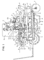
- the transplantation machine includes a main frame 4 frontwardly projecting upper and lower connecting pieces 1 and 2 for connection with a tractor (not shown) and provided driving wheels at rear side, and a movable frame 6 vertically pivotable about a driving shaft 5 transversely extended on the front side of the main frame 4.
- a movable frame 6 On the movable frame 6, rolling coulters 7, 7 for cutting foreign matter, openers 8, 8 for forming ridge grooves, seedling planting wheels 9, 9 for planting seedlings P in the ridge grooves and two sets of press down wheels 10, 10 for pressing down the planted seedlings P are arranged in sequential order from the front side to back side of the movable frame.
- a pair of left and right seedling supply units A, A for supplying respective seedling to the seedling planting wheels 9, 9 are also mounted on the movable frame 6.
- the seedling supply unit A is constructed with the preferred embodiment of the seedling pick-up device according to the present invention for picking up seedlings P from the seedling tray T, a tray transporting device V transporting the seedling tray T toward the seedling pick-up device B, and a transplantation unit E for transferring the seedling P picked up from the seedling pick-up device B to an outfeeding conveyer D.
- the seedling supply unit A constructed set forth above is integrally mounted on the movable frame 6 and a machine frame 11 vertically extending on the front side of the movable frame.
- the seedling tray T is formed by arranging a plurality of cylindrical hole shaped seedling storage cells (hereinafter simply referred to as "cell”) Ta, ... in a tray body of foamed styrol, in a lattice like array with a predetermined pitch ⁇ in back and forth and left and right directions.
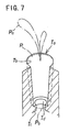
- Each cell Ta is formed with gradually reducing diameter from the upper surface opening Tb to a bottom portion Tc.
- a rod insertion hole Td is formed (Figs. 5 to 7 ) .
- the given pitch ⁇ is also provided between a front end face Te of the seedling tray T and a first row of the cells (in the same direction as a transporting direction ⁇ of the seedling tray).
- Such seedling tray T is horizontally mounted on the tray transporting device C in the upright position in each cell Ta in a condition positioning a leaf portion Pa of the seedling P upside.
- the tray transporting device C is constructed with a tray transporting drive portion F suspended in the lower portion of the center of a pair of laterally elongated side plates 12 and 13 and a tray transporting conveyer G driven by tray transporting drive portion F (Figs. 1 and 3).
- a construction of the tray transporting conveyer G is as follow.
- a tray transporting belt 16 is stretched on two belt stretching rollers 14 and 15 which are located at the rear end portion and an intermediate portion of the side plates. Between both belt stretching rollers 14 and 15, a belt holding plate 17 is arranged for holding an upper traveling portion 16a so that the upper traveling portion 16a of the tray transporting belt 16 forms a flat surface.
- a gear 19 is mounted via an electromagnetic clutch 18 (Figs. 4 and 5) permitting rotation in one direction, namely only movement of the upper traveling portion 16a of the tray transporting conveyer 16 in the direction of the downstream side in the transporting direction ⁇ of the seedling tray T. Via the electromagnetic clutch 18 and the gear 19, a driving force from the tray transporting drive portion F which will be discussed later, is transmitted to the belt stretching roller 15 (Fig. 5).
- a pair of tray supporting plates 20, 20 for supporting the seedling tray T transferred from the tray transporting conveyer G are arranged to be substantially flush with transverse members 20a, 20a extending laterally between the side plates 12 and 13 and the upper traveling portion 16a of the tray transporting belt 16 by a bracket (not shown) fixed to the transverse members 29a, 20a.
- tray retaining rollers 21, 21 which restrict lifting of the seedling tray T transported thereto, are provided on both sides across the transporting path of the seedling tray T.
- transverse members 22, 22 are extended therebetween.
- a link support shaft 25 is mounted via brackets 26, 26 arranged on both ends thereof.
- a snagglettoothed gear 23 meshing with the gear 19 is fixed at one end.
- suspension links 24, 24 arranged at both end portions the side plate support shaft 29 is suspended.
- a bracket 32 is rigidly secured.
- a drive rod 34 of a fluid pressure cylinder 33 such as pneumatic cylinder, hydraulic cylinder and so forth, is provided.
- a bracket 36 is rigidly secured at the center portion of a transverse member 35 extending transversely between the laterally extending side walls 12 and 13 located at lower portion of the tray transporting conveyer G.
- a bracket 36 is rigidly secured at the center portion of a transverse member 35 extending transversely between the laterally extending side walls 12 and 13 located at lower portion of the tray transporting conveyer G.
- a bracket 36 is rigidly secured.
- a cylinder body 37 of the fluid pressure cylinder 33 is mounted on the bracket 36.
- the snagglettoothed gear 23 is rotated within a predetermined angular range about the link support shaft 25. Associating with this, the belt stretching roller 15 is rotated intermittently in one direction via the gear 19 and the electromagnetic clutch 18.
- the tray transporting belt 16 intermittently drives the upper traveling portion 16a to travel with an internal of the arrangement pitch ⁇ of the cells Ta of the seedling tray T in the transporting direction ⁇ .
- the movable side plates 31, 31 also swing in back and forth direction.
- the seedling pick-up device B includes a seedling holding mechanism H for moving a seedling holding needle 38 which pierces and holds the seedling P, in vertical direction and the seedling pushing mechanism I which pushes up the seedling P stored in the cell Ta of the seedling tray T (Figs. 1, 3, 8).
- the seedling pushing mechanism I is constituted of two link mechanisms which are constructed as follows.
- a connecting member 44 is extended.
- a drive rod 47 of a fluid pressure cylinder 46 such as a hydraulic cylinder, is mounted via a bracket 45 which is provided at the center portion of the connecting member 44.
- a cylinder body 48 is pivotably supported by a bracket 50 provided at the center portion of a connecting member 49 extending transversely on the lower end portion at the center of the movable side plates 31, 31 (Figs . 3, 5, 8).
- the tray positioning rod 51 is formed to have cone-shaped tip end portion 51a, and an intermediate portion 51b following the tip end portion 51a is formed to have an external diameter matching with an internal diameter of rod insertion holes Td.
- the base end portion 51c is formed into cylindrical shape formed to have greater diameter than the rod insertion hole Td.
- the position error of the seedling tray T can be corrected to position the seedling tray T associating with insertion of the tray positioning rod 51 into the tray insertion hole Td.
- the seedling tray T can be accurately positioned.
- the tray positioning rods 51, 51 can be placed at a tray positioning position (b) and a stand-by position (c). Namely, by expansion and compression stroke of the drive rod 47 of the fluid pressure cylinder 46, the vertical lines 41, 41 are moved vertically via swing links 42, 42, 43, 43. Thus, the tray positioning rods 51, 51 are inserted into the cells Ta of the seedling tray T for reciprocally moving between the tray positioning position (b) for positioning the seedling tray T, and the stand-up position (c), in which the tray positioning rods 51, 51 move below the seedling tray.
- a connecting member 55 is extended transversely.
- a bracket 56 rigidly secured at the center of the connecting member 55, a drive rod 58 of a fluid pressure cylinder 57 is mounted on a bracket 56 rigidly secured at the center of the connecting member 55.
- the cylinder body 59 of the fluid pressure cylinder 57 is pivotably connected to a bracket 50 provided at the lower end portion at the center of the movable side plates 31, 31.
- a push rod support member 61 is extended transversely, on which seedling push rods 60 ... for pushing the seedlings P stored in the cells Ta arranged in rows in the seedling tray T, are extended vertically.
- the seedling pushing rods 60 ... are arranged in a distance equal to an arrangement pitch ⁇ of the cell Ta of the seedling tray T, on the upstream side of the transporting direction ⁇ of the seedling tray T from the tray positioning rod 51 (Figs. 1, 3, 8).
- Each seedling pushing rod 60 is a round-bas member having a thickness to be inserted into the rod insertion hole Td of the cell Ta of the seedling tray T.
- the seedling pushing rods 60 corresponding to respective cells Ta ... forming the row of the cells are arranged in the same number as that of the cells Ta ... in equal pitch ⁇ .
- the vertical links 52, 52 are moved vertically via the swing links 53, 53, 54, 54.
- the seedling contact surface of the seedling pushing rods 60 can be moved reciprocally between a pushing completion position (d) pushing the seedling contact surface to project upper side beyond the upper surface of the seedling tray and a pushing stand-by position (e) placing the seedling contact surface below the seedling tray T (Figs. 9 and 10).
- tray detection sensors 62, 62 for detecting the seedling tray T transported toward the tray positioning rod 51 are arranged.
- the seedling pushing rods 60 ... are driven to elevate upwardly by detecting the seedling tray T by the tray detection sensors 61, 62.
- the seedling tray T mounted on the tray transporting conveyer G are intermittently transported toward downstream side in the transporting direction ⁇ associating with expansion and compression stroke of the drive rod 34 of the fluid pressure cylinder 33 (Fig. 8).
- the tray positioning rod 51 is moved to the tray positioning position (b).
- the seedling pushing rod 60 is moved to the pushing stand-by position (e).
- the drive rod 34 of the fluid pressure cylinder 33 By several times of expansion and compression strokes of the drive rod 34 of the fluid pressure cylinder 33, the front end face Te of the seedling tray T comes into contact with the intermediate portion 51b of the tray positioning rod 51. On the other hand, at a position where the seedling pushing rod 60 matches with the seedling pick-up position (a), the drive cylinder 34 of the fluid pressure cylinder stops at expanded condition.
- the cells Ta ... forming the first row in the seedling tray T is moved to the seedling pick-up position (a).
- This condition is detected by the tray detection sensors 62, 62.
- the seedling pushing rod 60 ... are elevated upwardly to be inserted into respective cells Ta ... forming the first row.
- the seedling P stored in respective cells Ta are pushed up to be picked up (Fig. 9).
- the stand-by position of the tray positioning rod 51 (c) is driven to be lowered.
- the driving rod 34 of the fluid pressure cylinder 33 is contractingly driven.
- the tray positioning rod 51 is moved to the seedling pick-up position (a).
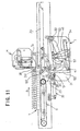
- the seedling pushing rod 60 is placed in opposition to the second row of the cells of the seedling tray T (Fig. 11).
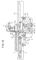
- the tray positioning rod 51 is moved upwardly to the tray positioning position (b) to be inserted into the cells Ta, Ta respectively located at the both ends of the first row of cells in the seedling tray T (Fig. 12). By this, the seedling tray T can be positioned by the tray positioning rod 51.
- the seedling tray T can be shifted for the arrangement pitch ⁇ of the cells Ta toward downstream side in the transporting direction ⁇ of the seedling tray T in the condition where the tray position rods 51 are inserted into the cells Ta, Ta in the first row of the cells. Then, the second row of cells Ta ... are moved to the seedling pick-up position (a) (Fig. 13).
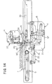
- the tray positioning rod 51 is moved to the pushing completed position (d) by driving the seedling push rods 60 ... upwardly, in the condition where the tray positioning rods 51 are maintained in the condition inserted into the cells Ta, Ta of both ends of the first row of the cells of the seedling tray T to push up the seedlings P stored in the cells Ta ... in the second row (Fig. 14).
- the seedling pushing rods 60 ... can be inserted into the cells in the Nth row of the seedling tray T for picking up the seedlings P. Subsequently, the tray positioning rods 51, 51 are moved for the arrangement pitch of the seedling storage cells Ta toward the downstream side in the transporting direction ⁇ of the seedling tray. Subsequently, the seedling pushing rod 60 is inserted into the cells Ta in the (N+1)th row. Thus, the seedlings P stored in the first row to subsequent rows are picked up in sequential order.
- the seedling holding mechanism H is supported the seedling holding needles 38 which are inserted into the cells Ta forming respective rows moved into the seedling pick-up position (a) for reciprocal movement between the seedling piercing position (f) placing the seedling holding needles in the closest position to the upper opening Tb of the cells Ta and a seedling release position (g) above the transporting conveyer for transferring the seedling P to the transporting conveyer D.
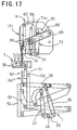
- the construction will be discussed for the case where the seedling holding mechanism H is shifted to the seedling piercing position (f) (Figs. 15, 16).
- a needle supporting member 64 On the read end portion side of a pair of side plates 63, 63, a needle supporting member 64, on which a plurality of seedling holding needles 38 ... are vertically provided in alignment on the tip end portion and a guide plate 67 formed with guide grooves 66 guiding the rollers 65, 65 arranged on both sides of the needle supporting member 64.
- the needle supporting member 64 is pivoted between the free end portions of swing arms 69, 69 pivoted the base end portion about a shaft extending between the front end portions of the left and right side plates 63, 63.
- a fluid pressure cylinder 73 utilizing fluid pressure, such as pneumatic pressure, hydraulic pressure or so forth, is disposed (Figs. 15 to 17).
- the fluid pressure cylinder 73 is adapted to be driven in synchronism with the seedling pushing mechanism I by detecting the seedling tray T by the tray detecting sensor 62.
- the seedling holding needle 38 is straight.
- the seedling holding needles 38 are arranged in alignment along the direction of the row of the cells with a pitch corresponding to the pitch ⁇ between the cells Ta of the seedling tray T, each two needles for each cell.
- the seedling release plate 74 on which needle loosely insertion holes (not shown), loosely receiving respective seedling holding needles 38 are provided in alignment, are provided.
- a drive rod 73a of the fluid pressure cylinder 73 is driven for compression to downwardly drive the seedling holding needles 38 to pierce the seedlings P stored in the cells Ta ...
- the seedling pushing rods 60 are moved upwardly to contact the seeding contact faces with the bottom surface of the seedlings P within the cells Ta.
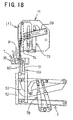
- the seedling holding needles 38 are driven upwardly at the same speed as that of the seedling pushing rods 60 (Fig. 18).
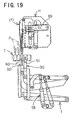
- the seedlings P are maintained in the position pierced by the seedling holding needles 38, and is moved to the pushing completed position (d) (Fig, 19) in the condition supported from the lower side by the seedling pushing rods 60 for preventing loosing off.
- the construction of the transfer device E is as follow.
- a connection pipe 76 is transversely extended between the upper end portions of a pair of left and right side plates 75, 75. Between support legs 77 to 79 vertically extended from the side plates 75, 75, support shafts 81 fixed brackets 80, 80 at both ends thereof, are rotatably extended thereacross. On the other hand, between the support legs 77 and 78, a motor M is fixed. In conjunction therewith, a rotary shaft 84, on which a drive gear 83 meshes with a gear 82 fixed to a drive shaft of the motor M, is fixed at the inner end portion.
- the pivotal arms 87 and 87 are pivoted for shifting the seedling holding mechanism H between the seedling piecing position (f) and the seedling release position (g).
- a small gear 91 meshing with the drive gear 83 is fixed. Also, on the brackets 80, 80 provided on both ends of the support shaft 81, the upper end portion of support arms 93, 93 pivoting the side plates 63, 63 of the seedling holding mechanism H, are mounted via a shaft 92 which is provided between the lower end portions between the brackets 80, 80.
- the eccentric shaft 83a is moved from the drive starting position (h) to the drive terminating position (i) to cause upward pivotal movement of the brackets 80, 80.
- a force for upwardly pivoting about the shaft 86 of the pivotal arms 87, 87 acts on the side plates 63, 63 of the seedling holding mechanism H.
- the seedling holding mechanism H is upwardly pivoted over 90° about the shaft 86 so that the seedling holding needles 38 is oriented in substantially horizontal direction. With maintaining this attitude, the seedling holding mechanism H is moved to the seedling release position (g).
- the seedling holding mechanism H is returned from the seedling release position (g) to the seedling piercing direction (f) through the reversed path.
- the transporting conveyer D is supported about a tray space SP defined on the front end portion of a pair of left and right side plates 12 and 13, at the upper end portion of the machine frame 11.
- a vertical conveyer 94 transporting the seedling P toward seedling planting rings 9, 9, is provided (Fig. 1).
- the seedling pushing rod 600 is returned to the pushing stand-by position (e).
- the seedling holding mechanism H is shifted from the seedling piercing position (f) to the seedling release position (g). During this, the seedling holding mechanism H is pivoted over 90° about the shaft 86.
- the fluid pressure cylinder 73 of the seedling holding mechanism H is driven to expand the drive rod to abruptly retract the seedling holding needle 38 between the side plates 63, 63.
- each seedling P pierced by the seedling holding needle 38 is released by the seedling release plate 74.
- the seedling is released on the outfeeding conveyer D located at the lower position.
- the seedling P released on the outfeeding conveyer D is subsequently transferred to the vertical conveyer 94 and transported toward the seedling planting ring 9.
- the seedling holding mechanism H In conjunction with releasing of the seedling P, the seedling holding mechanism H is moved to return to the seedling piercing position (f), and the seedling pushing rod 60 of the seedling pushing mechanism I is returned to the pushing stand-by position (e). Then, the seedling tray T is intermittently transported to place the next row of the cells at the seedling pick-up position (a).
- the tray positioning rod is inserted into a part of the seedling storage cells in the row or rows other than the row of the cells, to which the seedling pushing rods are about inserted.
- the positioning may be done in the following manner.
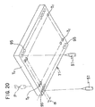
- a seedling tray T' shown in Fig. 20 is formed with a plurality of positioning rod insertion holes 95 ... in both side portions of the bottom surface. In parallel to the transporting direction ⁇ of the seedling tray T' and with an interval consistent with the arrangement pitch ⁇ of the cells Ta ... , the positioning rod insertion holes 95 ... are aligned.
- the positioning rod insertion hole 95 may be the same shape as the cell Ta, or, in the alternative, the positioning rod insertion hole 95 may be formed in recessed manner in the bottom surface so that it may not be seen from the upper surface of the seedling tray T'.
- a plurality of positioning rod insertion holes 95 ... are formed in both side portions of the bottom surface of the seedling tray T' in parallel to the transporting direction ⁇ of the seedling tray T' and in alignment in a pitch corresponding to the arrangement pitch ⁇ of the cells Ta ..., the arranging position of the tray positioning rods 51, 51 of the seedling pushing mechanism I, the seedling tray T' can be transported only by arranging pairs of left and right rod insertion holes 95, 95 at an interval for placing the rod insertion holes in opposition to the tray positioning rods 51, 51.
- a plurality of positioning rod insertion holes 95 ... is not limited to those formed in the pitch corresponding to the arrangement pitch ⁇ of the cells Ta ... but can be any necessary interval. In this case, by setting the interval of the positioning rod insertion holes in 1/n (n is integer) of the arrangement pitch ⁇ of the cells Ta ..., the seedling tray T' can be easily transported.
- tray positioning rods are inserted into two cells in the same row
- the present invention should not be limited to the shown construction. It is possible to position the seedling tray by inserting two tray positioning rods into the cells in different rows. Furthermore, number of the tray positioning rods is not specified to two but can be three or more for positioning the seedling tray.
Abstract
Description
- The present invention relates to a method and a device for picking up seedlings from a seedling tray, and inparticular for picking up seedlings from a plurality of seedling storage cells formed in a seedling tray.
- As the conventional seedling picking up device from a seedling tray, there is a device disclosed in JP-A-07184421.
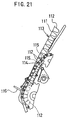
- As shown in Fig. 21, the conventional seedling tray transporting apparatus is constructed with a
seedling tray 113, in which a plurality ofseedling storage cells 112 are embossed in a sheetform tray body 111, and a transportingmember 115 transversely extending between a pair of transporting strips 114, 114 (only one is shown), being inserted between adjacentseedling storage cells seedling storage cells 112 by the transportingmember 115 to stop each of the seedling storage cells at a predetermined seedling picking up position, at which a seedling picking upclaw 116 is provided. - However, the conventional device encounters the following problems.
- (1) As the seedling tray, in addition to a sheet type, in
which a plurality of
seedling storage cells 112 are embossed, as set forth above, there is a board type, in which a plurality of seedling storage cells is recessed in a board form tray body. In the conventional transporting device, in which theseedling storage cells 112 are pushed by the transportingmember 115 inserted between adjacentseedling storage cells 112, it is not possible to transport the board type cell having flat bottom surface. - (2) When other sheet type seedling tray which differentiates arrangement pitch and the size of the seedling storage cells, is used, it does not become possible to register the seedling storage cell to the predetermined seedling picking up position unless the traveling pitches of the transporting strips 114, 114 are significantly differentiated. Therefore, complicate exchanging operation becomes necessary for respective of different types of the seedling tray for lowering work efficiency.
-
- It is desirable to enable picking-up the seedling by stopping the seedling storage cell at predetermined seedling pick-up position even when the arrangement pitches of the seedling storage cells and/or the sizes are different in the seedling storage cells or the types of the seedling trays are different, such as the sheet type, board type and so forth. This can be achieved by an apparatus detecting the front end face of the seedling tray in the transporting direction by a tray detecting sensor to stop the first row of the seedling storage cells in the seedling tray at the seedling pick-up position, subsequently calculating a transporting distance of the seedling tray from the detected position of the front end face of the seedling tray in the transporting direction by the tray detection sensor, making judgment whether the calculated transporting distance matches with the arrangement pitch or not so that the seedling tray is stopped every time of matching of the transporting distance and the predetermined arrangement pitch of the seedling storage cells and thereby stopping the each row of the seedling storage cells at the seedling pick-up position.
- However, in the foregoing transporting device of the seedling tray, irrespective of the actual transporting distance of the seedling tray, the seedling tray is stopped when the arithmetically calculated transporting distance matches with the predetermined pitch. Therefore, it is possible that the actual transporting distance and the calculated transporting distance become inconsistent due to accumulated error of a measured value to be a reference in calculation of the transporting distance or a play in the transporting mechanism portion of the seedling tray.
- In such case, the position of the seedling pushing rod and the rod insertion hole in the bottom portion of the seedling storage cells of the seedling tray causes offset to make insertion of the seedling pushing rod into the seedling storage cells to thus make it impossible to pick-up the seedling from the seedling tray.
- On the other hand, in the transporting path of the seedling tray, it is typical to arrange a guide rail or the like so that the seedling tray may travel in straight. However, in certain setting of the gap between the guide rail and the seedling tray, the seedling tray may be transported in the tilted attitude. In such case, the seedling pushing rod and the rod insertion hole in the bottom portion of the seedling storage cells of the seedling tray become offset to each other to make it impossible to pick-up the seedling from the seedling tray. Also, transportation of the seedling tray in the tilted attitude can be caused when the tray is worn or deformed.
- The prior art document WO 94 03040 A discloses a method and an apparatus for picking up seedlings from a seedling tray. The seedlings are picked up per each row of storage cells from in alignment at a predetermined pitch. There are provided tray positioning rods (pegs linked together and actuated by cylinders) for positioning (indexing) the tray. The pegs move perpendicular to the moving direction of the tray. Further, seedling pushing rods perform an inserting operation.
- According to the above mentioned document, the trays have, in addition to holes in the bottom walls thereof for being used to push seedlings by means of seedling pushing rods, holes in the side walls for being used to receive pegs for indexing the tray. Further, the tray is (or can be) moved while being in a vertical position.
- It is the object of the present invention to provide a method and a device for picking up seedlings from a seedling tray which can reliably establish opposing position of a seedling storage cell and a seedling pushing rod irrespective a transporting attitude of the seedling tray and even when wearing or deformation is caused on the seedling tray without the need for forming any special holes in the seedling tray.
- This object is solved by a method as defined in
claim 1 and a device as defined inclaim 8. The respective dependent claims 2 to 7 and 9 to 17 show advantageous further developments of the method and the device according to the present invention. - Especially, rod insertion holes of the seedling storage cells are used for positioning the seedling tray as well as for pushing seedlings. The tray positioning rods according to the present invention are provided in front of the seedling pushing rods and beneath the tray to be positioned. The tray positioning rods according to the present invention are provided for positioning the tray. According to the present invention, the tray is moved while the seedlings are provided in an upright position and the tray positioning rods as well as the seedling pushing rods are provided so as to contact the trays by means of holes in the bottom walls thereof, while the trays are moved in a horizontal position.
- A seedling tray, in which a plurality of seedling storage cells are formed, is positioned at a predetermined position and an insertion of seedling pushing rods is performed in the positioned condition of the seedling tray.
- According to the present invention, a device for picking up seedlings from a seedling tray comprises tray positioning rods for positioning the seedling tray at the predetermined position and seedling pushing rods to be inserted into respective of the seedling storage cells with maintaining the seedling tray at the condition positioned at the predetermined position.
- According to the present invention, a method for picking up seedlings from a seedling tray by inserting a seedling pushing rod into rod insertion holes formed in bottoms of respective of seedling storage cells per each row of the seedling storage cells formed in alignment at a predetermined pitch in the seedling tray transported in one direction, comprises the steps of:
- positioning the seedling tray at a predetermined position by means of a tray positioning rod; and
- inserting the seedling pushing rods with maintaining the seedling tray in the positioned condition.
-
- According to the present invention, the seedling can be securely picked up with accurately opposing the seedling storage cells and the seedling pushing rods even when the seedling tray is transported in tilted fashion and furthermore even when wearing or deformation is caused in the seedling tray.
- In the preferred construction, the tray positioning rods may be inserted into some of the seedling storage cells in a row other than a row of the seedling storage cells, to which the seedling pushing rods are about inserted.
- The seedling tray may be positioned by inserting the tray positioning rod into some of the seedling storage cells in Nth row and the seedling pushing rods are inserted into the seedling storage cells in (N+1)th row.
- The seedling tray may be positioned by inserting the tray positioning rod into some of the seedling storage cells in Nth row, the tray positioning rod is moved in a magnitude corresponding to an arrangement pitch of the seedling storage cells, toward downstream in a transporting direction of the seedling tray with maintaining the condition where the tray positioning rod is inserted into some of the seedling storage cells, and the seedling pushing rods are inserted into respective of the seedling storage cells in (N+1)th row. The seedling tray may be positioned by abutting the tray positioning rod to a front end face of the seedling tray, the seedling pushing rods are inserted into respective of the seedling storage cells in a Nth row for picking up the seedling stored therein, subsequently, the seedling tray is positioned by inserting the tray positioning rod into some of the seedling storage cells in Nth row, the tray positioning rod is moved in a magnitude corresponding to an arrangement pitch of the seedling storage cells, toward downstream in a transporting direction of the seedling tray with maintaining the condition where the tray positioning rod is inserted into some of the seedling storage cells, and the seedling pushing rods are inserted into respective of the seedling storage cells in (N+1)th row. A plurality of tray positioning holes for inserting the tray position rod in alignment at predetermined interval, may be formed in the seedling tray, and the seedling tray is positioned by inserting the tray positioning rod in the tray positioning hole. The tray positioning rod may be shifted in the magnitude corresponding to the arrangement pitch of the seedling storage cells toward downstream side of a transporting direction of the seedling tray with maintaining a condition where the tray positioning rod is inserted in some of the tray positioning hole, and then insertion of the seedling pushing rods into the seedling storage cells is performed.
- With the construction set forth above, the seedling tray can be transported by a predetermined arrangement pitch. Also, it is not necessary to position the seedling tray after once transport for the predetermined arrangement pitch. Furthermore, the front end face of the seedling tray is abutted on the tray positioning rod to initially position the seedling tray accurately. On the other hand, in the alternative construction set forth above, the dedicated tray positioning holes are formed so that the tray positioning rods are inserted into the dedicated tray positioning holes without inserting the same into openings at the bottom of the seedling storage cells. Therefore, the seedling tray or the seedling storage cells may not be damaged by the tray positioning rods during seedling pick-up operation.
- The method further comprises the use of seedling holding needles to be downwardly shifted into the seedling storage cells from upper surface opening thereof for piercing and holding the seedling stored in the seedling storage cells by the seedling holding needles. Then, the seedling pushing rods are elevated upwardly to abut onto the bottom surface of the seedling pierced and held by the seedling holding needles under pressure for pushing up the seedling by elevating the seedling holding needles and the seedling pushing rods at the same speed.
- With the construction set forth above, it becomes possible to prevent drop out of the seedling pierced by the seedling holding needle. Furthermore, since the seedling is pierced while it is stored in the seedling storage cells, the seedling can be securely pierced with maintaining the upright position.
- According to the present invention, a device for picking up seedlings from a seedling tray per each row of the seedling storage cells formed in alignment at a predetermined pitch in the seedling tray transported in one direction, comprises:
- a tray positioning rod for positioning the seedling tray from which the seedlings stored in the respective seedling storage cells are to be picked up; and
- seedling pushing rods performing insertion operation for respective of seedling storage cells with maintaining a condition where the seedling tray is positioned at a predetermined position by the tray positioning rod.
-
- According to the present invention, a device for picking up seedlings from a seedling tray per each row of the seedling storage cells formed in alignment at a predetermined pitch in the seedling tray transported in one direction, comprises:
- a tray positioning rod being inserted into some of the seedling storage cells in a row other than a row of the seedling storage cells, to which the seedling pushing rods are about inserted, for positioning the seedling tray from which the seedlings stored in the respective seedling storage cells are to be picked up; and
- seedling pushing rods performing insertion operation for respective of seedling storage cells with maintaining a condition where the seedling tray is positioned at a predetermined position by inserting the tray positioning rod into some of the seedling storage cells.
-
- According to the present invention, a device for picking up seedlings from a seedling tray per each row of the seedling storage cells formed in alignment at a predetermined pitch in the seedling tray transported in one direction, comprises:
- a tray positioning rod being inserted into some of the seedling storage cells in a Nth row, for positioning the seedling tray from which the seedlings stored in the respective seedling storage cells are to be picked up; and
- seedling pushing rods performing insertion operation for respective of seedling storage cells in (N+1)th row with maintaining a condition where the seedling tray is positioned at a predetermined position by inserting the tray positioning rod into some of the seedling storage cells in the Nth row.
-
- According to the above described aspects of the present invention, the same effect as that of the firstly described aspect of the invention can be achieved.
- The device may further comprise a tray transporting device intermittently transporting the seedling tray by shifting in the magnitude corresponding to arrangement pitch of the seedling storage cells toward downstream side in the transporting direction of the seedling tray with maintaining the condition where the tray positioning rod is inserted into some of the seedling storage cell in the seedling tray. The tray position rod and the seedling pushing rods may be arranged with an interval corresponding to the arrangement pitch of the seedling storage cells. The tray positioning rod and the seedling pushing rods may be simultaneously shifted with maintaining an interval between each other constant in the transporting direction of the seedling tray, and shifted in vertical direction independently of the other. The device may further comprise two link mechanisms supporting the tray positioning rod and the seedling pushing rods in vertically movable fashion independently of the other, a seedling pushing mechanism provided in each link mechanism and constituted of a fluid pressure cylinder, and a tray transporting driving portion reciprocally shifting the seedling pushing mechanism at the same stroke as the arrangement pitch of the seedling storage cell in the transporting direction of the seedling tray.
- By positioning the seedling tray by means of the tray positioning rod, the seedling pushing rods may be opposed to the seedling storage cells. By this, the mechanism for positioning the seedling tray can be simplified to shorten the period required for positioning.
- The tray positioning rod may be arranged at a position opposing the seedling storage cell arranged at the most outside of the seedling storage cell in the row of cells.
- The tray positioning rod is inserted into the seedling storage cells arranged at the outermost position of the seedling storage cells to simplify the construction with assuring positioning.
- According to the present invention, a device for picking up seedlings from a seedling tray per each row of the seedling storage cells formed in alignment at a predetermined pitch in the seedling tray transported in one direction, comprises:
- a plurality of positioning rod insertion holes formed in the seedling tray in parallel to a transporting direction of the seedling tray and in alignment with a predetermined interval;
- tray positioning rods to be inserted into some of the positioning rod insertion holes for positioning the seedling tray; and
- seedling pushing rods performing insertion operation for respective of the seedling storage cells with maintaining the condition where the tray position rods are inserted into some of the positioning rod insertion holes for positioning.
-
- The tray positioning holes for inserting the tray positioning rods are formed instead of opening the bottom portions of the seedling storage cells. Therefore, it will not be possible to damage the thin bottom portion of the seedling storage cells as in the case where the tray positioning rods are inserted into the openings formed in the bottom portion of the seedling tray having thin wall thickness.
- The device may further comprise a tray transporting device intermittently transporting the seedling tray by shifting in the magnitude corresponding to arrangement pitch of the seedling storage cells toward downstream side in the transporting direction of the seedling tray with maintaining the condition where the tray positioning rod is inserted into some of the positioning rod insertion.
- The positioning rod insertion holes may be formed in alignment with an interval corresponding to the arrangement pitch of the seedling storage cells.
- The positioning rod may have a tip end portion formed into cone shaped configuration, and an intermediate portion following to the tip end portion, which intermediate portion has an external diameter matching with an internal diameter of the positioning rod insertion hole.
- With the construction set forth above, even when the seedling tray is slightly offset, the seedling tray can be accurately positioned within correcting the offset associating with insertion of the tray positioning rod into the rod insertion hole as long as the tip end of the tray positioning rod is placed in opposition with the rod insertion hole.
- Furthermore, since the intermediate portion of the tray positioning rod is provided with the external diameter corresponding to the internal diameter of the rod insertion hole, positioning of the seeding tray can be accurate.
- The present invention will be understood more fully from the detailed description given herebelow and from the accompanying drawings of the preferred embodiment of the present invention, which, however, should not be taken- to be limitative to the invention, but are for explanation and understanding only.
- In the drawings:
- Fig. 1 is a side elevation of a seedling transplantation machine, in which the preferred embodiment of a seedling picking-up device from a seedling tray according to the present invention is installed;
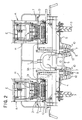
- Fig. 2 is a front elevation of the seedling transplantation machine of Fig. 1;
- Fig. 3 is a side elevation of a seedling supply unit, in which is illustrated a condition where a f irst row of cells of the seedling tray is moved to a seedling pick-up position;
- Fig. 4 is a front elevation of the seedling supply unit of Fig. 3;
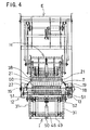
- Fig. 5 is an enlarged front elevation of the portion around the seedling pick-up position;
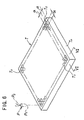
- Fig. 6 is a perspective view of a seedling tray;
- Fig. 7 is a partial section taken along line VII - VII of Fig. 6;
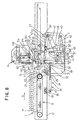
- Fig. 8 is an explanatory illustration showing operation of a tray transporting device and a seedling push-up mechanism, in which a condition is illustrated where the seedling tray is transported toward the seedling pick-up position;
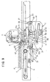
- Fig. 9 is an explanatory illustration showing operation of a tray transporting device and a seedling push-up mechanism similar to Fig. 8, in which a condition is illustrated where the seedling tray is positioned by abutting the front end face thereof on a tray positioning rod and the seedling is picked up with maintaining the positioned condition;
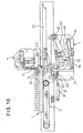
- Fig. 10 is an explanatory illustration showing operation of a tray transporting device and a seedling push-up mechanism similar to Fig. 8, in which a condition is illustrated, where the seedling tray is maintained in place and the tray positioning rod and a seedling pushing rod are lowered;
- Fig. 11 is an explanatory illustration showing operation of a tray transporting device and a seedling push-up mechanism similar to Fig. 8, in which a condition is illustrated, where the seedling tray is maintained in place and the tray positioning rod is moved to the seedling pick-up position;
- Fig. 12 is an explanatory illustration showing operation of a tray transporting device and a seedling push-up mechanism similar to Fig. 8, in which a condition is illustrated, where the tray positioning rod is moved to a tray positioning position for positioning the seedling tray;
- Fig. 13 is an explanatory illustration showing operation of a tray transporting device and a seedling push-up mechanism similar to Fig. 8, in which a condition is illustrated, where the tray positioning rod is moved in a magnitude corresponding to a predetermined pitch of the seedling storage cell toward downstream side in the transporting direction of the seedling tray;
- Fig. 14 is an explanatory illustration showing operation of a tray transporting device and a seedling push-up mechanism similar to Fig. 8, in which a condition is illustrated where a seedling is picked up from the seedling storage cell while the seedling tray is positioned by the tray positioning rod;
- Fig. 15 is an enlarged side elevation of a transplanting unit and a seedling holding mechanism;
- Fig. 16 is a front elevation of the transplanting unit and the seedling holding mechanism of Fig. 15;
- Fig. 17 is an explanatory illustration showing operation of a seedling pushing mechanism and the seedling holding mechanism, in which a condition is illustrated, where the seedling tray is positioned by the tray positioning rod and a seedling holding needle is lowered within the seedling storage cells;
- Fig. 18 is an explanatory illustration showing operation of a seedling pushing mechanism and the seedling holding mechanism similar to Fig. 17, in which a condition is illustrated, where the seedling holding needle piercing and holding the seedling, and the seedling push rod are elevated synchronously with each other;
- Fig. 19 is an explanatory illustration showing operation of a seedling pushing mechanism and the seedling holding mechanism similar to Fig. 17, in which a condition is illustrated, where the seedling holding needle and the seedling push rod are moved to a pushing completion position;
- Fig. 20 is a perspective view of the seedling tray formed with a positioning rod insertion hole; and
- Fig. 21 is a side elevation of the major part of the conventional transporting device of the seedling tray.
-
- The present invention will be discussed hereinafter in detail in terms of the preferred embodiment of the present invention with reference to the accompanying drawings. In the following description, numerous specific details are set forth in order to provide a thorough understanding of the present invention. It will be obvious, however, to those skilled in the art that the present invention may be practiced without these specific details. In other instance, well-known structures are not shown in detail in order to avoid unnecessary obscure the present invention.
- Hereinafter, the preferred embodiment of a seedling pick-up device for picking-up a seedling from a seedling tray, according to the present invention will be discussed together with general construction of a seedling transplantation machine, into which the same is installed.
- The transplantation machine includes a
main frame 4 frontwardly projecting upper and lower connectingpieces 1 and 2 for connection with a tractor (not shown) and provided driving wheels at rear side, and amovable frame 6 vertically pivotable about a drivingshaft 5 transversely extended on the front side of themain frame 4. On themovable frame 6, rollingcoulters openers seedling planting wheels wheels seedling planting wheels movable frame 6. - The seedling supply unit A is constructed with the preferred embodiment of the seedling pick-up device according to the present invention for picking up seedlings P from the seedling tray T, a tray transporting device V transporting the seedling tray T toward the seedling pick-up device B, and a transplantation unit E for transferring the seedling P picked up from the seedling pick-up device B to an outfeeding conveyer D. The seedling supply unit A constructed set forth above is integrally mounted on the
movable frame 6 and amachine frame 11 vertically extending on the front side of the movable frame. - The seedling tray T is formed by arranging a plurality of cylindrical hole shaped seedling storage cells (hereinafter simply referred to as "cell") Ta, ... in a tray body of foamed styrol, in a lattice like array with a predetermined pitch α in back and forth and left and right directions. Each cell Ta is formed with gradually reducing diameter from the upper surface opening Tb to a bottom portion Tc. Also, in the bottom portion Tc, a rod insertion hole Td is formed (Figs. 5 to 7 ) . On the other hand, the given pitch α is also provided between a front end face Te of the seedling tray T and a first row of the cells (in the same direction as a transporting direction β of the seedling tray).
- Such seedling tray T is horizontally mounted on the tray transporting device C in the upright position in each cell Ta in a condition positioning a leaf portion Pa of the seedling P upside.
- The tray transporting device C is constructed with a tray transporting drive portion F suspended in the lower portion of the center of a pair of laterally elongated
side plates - A construction of the tray transporting conveyer G is as follow.
- Between the laterally elongated
side plates tray transporting belt 16 is stretched on twobelt stretching rollers belt stretching rollers belt holding plate 17 is arranged for holding anupper traveling portion 16a so that the upper travelingportion 16a of thetray transporting belt 16 forms a flat surface. - On one end portion of the
belt stretching roller 15, agear 19 is mounted via an electromagnetic clutch 18 (Figs. 4 and 5) permitting rotation in one direction, namely only movement of the upper travelingportion 16a of thetray transporting conveyer 16 in the direction of the downstream side in the transporting direction β of the seedling tray T. Via theelectromagnetic clutch 18 and thegear 19, a driving force from the tray transporting drive portion F which will be discussed later, is transmitted to the belt stretching roller 15 (Fig. 5). - From the intermediate portion to the front end portion of the laterally elongated
side plates tray supporting plates transverse members side plates portion 16a of thetray transporting belt 16 by a bracket (not shown) fixed to thetransverse members 29a, 20a. - On the upper side of the rear end of the
tray supporting plates tray retaining rollers - The construction of the tray transporting drive portion F is as follow.
- At the intermediate portion of the laterally elongated
side plates transverse members 22, 22 (only one is shown) are extended therebetween. On thetransverse member 22 on the upstream side of the transporting direction β among thesetransverse members link support shaft 25 is mounted viabrackets link support shaft 25,asnagglettoothed gear 23 meshing with thegear 19 is fixed at one end. Also, via suspension links 24, 24 arranged at both end portions, the sideplate support shaft 29 is suspended. - On the both ends of the side
plate supporting shafts movable side plates - At the center portion of the side
plate support shaft 29, abracket 32 is rigidly secured. On thebracket 32, adrive rod 34 of afluid pressure cylinder 33, such as pneumatic cylinder, hydraulic cylinder and so forth, is provided. On the other hand, at the center portion of atransverse member 35 extending transversely between the laterally extendingside walls bracket 36 is rigidly secured. On thebracket 36, a cylinder body 37 of thefluid pressure cylinder 33 is mounted. - By expansion and compression strokes of the
drive rod 34 of thefluid pressure cylinder 33, thesnagglettoothed gear 23 is rotated within a predetermined angular range about thelink support shaft 25. Associating with this, thebelt stretching roller 15 is rotated intermittently in one direction via thegear 19 and theelectromagnetic clutch 18. - Accordingly, the
tray transporting belt 16 intermittently drives the upper travelingportion 16a to travel with an internal of the arrangement pitch α of the cells Ta of the seedling tray T in the transporting direction β. On the other hand, associating with expansion and compression strokes of thedrive rod 34, themovable side plates - Next, the seedling pick-up device B includes a seedling holding mechanism H for moving a
seedling holding needle 38 which pierces and holds the seedling P, in vertical direction and the seedling pushing mechanism I which pushes up the seedling P stored in the cell Ta of the seedling tray T (Figs. 1, 3, 8). - The seedling pushing mechanism I is constituted of two link mechanisms which are constructed as follows.
- Between the upper and lower ends of the front side of the
movable side plates link supporting shafts - On the
link supporting shafts 39, base end portions of a pair ofswing links link support shaft 40, base end portions of a pair ofswing links lower swing links vertical links - Between the swing links 42, 42, a connecting
member 44 is extended. Adrive rod 47 of afluid pressure cylinder 46, such as a hydraulic cylinder, is mounted via abracket 45 which is provided at the center portion of the connectingmember 44. On the other hand, acylinder body 48 is pivotably supported by abracket 50 provided at the center portion of a connectingmember 49 extending transversely on the lower end portion at the center of themovable side plates 31, 31 (Figs . 3, 5, 8). - Between upper end portions of the
vertical links tray positioning rods - The
tray positioning rod 51 is formed to have cone-shaped tip end portion 51a, and anintermediate portion 51b following the tip end portion 51a is formed to have an external diameter matching with an internal diameter of rod insertion holes Td. On the other hand, thebase end portion 51c is formed into cylindrical shape formed to have greater diameter than the rod insertion hole Td. - Namely, even when the seedling tray T is slightly shifted, as long as the cone-shaped tip end portion 51a is placed in opposition to the rod insertion hole Td, the position error of the seedling tray T can be corrected to position the seedling tray T associating with insertion of the
tray positioning rod 51 into the tray insertion hole Td. - Furthermore, by inserting and engaging the
intermediate portion 51b in the rod insertion hole Td, the seedling tray T can be accurately positioned. - The
tray positioning rods drive rod 47 of thefluid pressure cylinder 46, thevertical lines tray positioning rods tray positioning rods - On the
link support shaft 39, the base end portions of a pair of upper andlower swing links link support shaft 40, the base end portion of a pair ofsing links swing links vertical links - Furthermore, between the
vertical links member 55 is extended transversely. On abracket 56 rigidly secured at the center of the connectingmember 55, adrive rod 58 of afluid pressure cylinder 57 is mounted. Thecylinder body 59 of thefluid pressure cylinder 57 is pivotably connected to abracket 50 provided at the lower end portion at the center of themovable side plates - Between the upper end portions of the
vertical links rod support member 61 is extended transversely, on which seedling pushrods 60 ... for pushing the seedlings P stored in the cells Ta arranged in rows in the seedling tray T, are extended vertically. - The
seedling pushing rods 60 ... are arranged in a distance equal to an arrangement pitch α of the cell Ta of the seedling tray T, on the upstream side of the transporting direction β of the seedling tray T from the tray positioning rod 51 (Figs. 1, 3, 8). - Each
seedling pushing rod 60 is a round-bas member having a thickness to be inserted into the rod insertion hole Td of the cell Ta of the seedling tray T. Theseedling pushing rods 60 corresponding to respective cells Ta ... forming the row of the cells are arranged in the same number as that of the cells Ta ... in equal pitch α. - By expansion and compression strokes of the
drive rod 58 of thefluid pressure cylinder 57, thevertical links seedling pushing rods 60 ... can be moved reciprocally between a pushing completion position (d) pushing the seedling contact surface to project upper side beyond the upper surface of the seedling tray and a pushing stand-by position (e) placing the seedling contact surface below the seedling tray T (Figs. 9 and 10). - On the upstream side in the transporting direction β of the seedling tray T at the tray positioning position (b) where the
tray positioning rod 51 is in upwardly shifted position,tray detection sensors tray positioning rod 51, are arranged. - When the
tray positioning rods seedling pushing rods 60 ... are driven to elevate upwardly by detecting the seedling tray T by thetray detection sensors - Operation of the tray transporting device C and the seedling pushing mechanism I constructed as set forth above, will be discussed with reference to Figs. 8 to 14.
- The seedling tray T mounted on the tray transporting conveyer G are intermittently transported toward downstream side in the transporting direction β associating with expansion and compression stroke of the
drive rod 34 of the fluid pressure cylinder 33 (Fig. 8). - At this time, the
tray positioning rod 51 is moved to the tray positioning position (b). On the other hand, theseedling pushing rod 60 is moved to the pushing stand-by position (e). - By several times of expansion and compression strokes of the
drive rod 34 of thefluid pressure cylinder 33, the front end face Te of the seedling tray T comes into contact with theintermediate portion 51b of thetray positioning rod 51. On the other hand, at a position where theseedling pushing rod 60 matches with the seedling pick-up position (a), thedrive cylinder 34 of the fluid pressure cylinder stops at expanded condition. - By contacting the front end face Te of the seedling tray T onto the
intermediate portion 51b of thetray positioning rod 51, the cells Ta ... forming the first row in the seedling tray T is moved to the seedling pick-up position (a). This condition is detected by thetray detection sensors tray detection sensors seedling pushing rod 60 ... are elevated upwardly to be inserted into respective cells Ta ... forming the first row. By this, the seedling P stored in respective cells Ta are pushed up to be picked up (Fig. 9). - In the condition where the seedling tray T is stopped, the stand-by position of the tray positioning rod 51 (c) is driven to be lowered. In conjunction therewith, after driving to lower the
seedling pushing rod 60 to the pushing stand-by position (e) (Fig. 10), the drivingrod 34 of thefluid pressure cylinder 33 is contractingly driven. Thetray positioning rod 51 is moved to the seedling pick-up position (a). In conjunction therewith, theseedling pushing rod 60 is placed in opposition to the second row of the cells of the seedling tray T (Fig. 11). In the seedling pick-up position (a), thetray positioning rod 51 is moved upwardly to the tray positioning position (b) to be inserted into the cells Ta, Ta respectively located at the both ends of the first row of cells in the seedling tray T (Fig. 12). By this, the seedling tray T can be positioned by thetray positioning rod 51. - Next, by driving the
drive rod 34 of thefluid pressure cylinder 33 for expansion, the seedling tray T can be shifted for the arrangement pitch α of the cells Ta toward downstream side in the transporting direction β of the seedling tray T in the condition where thetray position rods 51 are inserted into the cells Ta, Ta in the first row of the cells. Then, the second row of cells Ta ... are moved to the seedling pick-up position (a) (Fig. 13). - Then, the
tray positioning rod 51 is moved to the pushing completed position (d) by driving theseedling push rods 60 ... upwardly, in the condition where thetray positioning rods 51 are maintained in the condition inserted into the cells Ta, Ta of both ends of the first row of the cells of the seedling tray T to push up the seedlings P stored in the cells Ta ... in the second row (Fig. 14). - Thus, the
seedling pushing rods 60 ... can be inserted into the cells in the Nth row of the seedling tray T for picking up the seedlings P. Subsequently, thetray positioning rods seedling pushing rod 60 is inserted into the cells Ta in the (N+1)th row. Thus, the seedlings P stored in the first row to subsequent rows are picked up in sequential order. - Next, the seedling holding mechanism H is supported the
seedling holding needles 38 which are inserted into the cells Ta forming respective rows moved into the seedling pick-up position (a) for reciprocal movement between the seedling piercing position (f) placing the seedling holding needles in the closest position to the upper opening Tb of the cells Ta and a seedling release position (g) above the transporting conveyer for transferring the seedling P to the transporting conveyer D. The construction will be discussed for the case where the seedling holding mechanism H is shifted to the seedling piercing position (f) (Figs. 15, 16). - On the read end portion side of a pair of
side plates needle supporting member 64, on which a plurality ofseedling holding needles 38 ... are vertically provided in alignment on the tip end portion and aguide plate 67 formed withguide grooves 66 guiding therollers needle supporting member 64. - The
needle supporting member 64 is pivoted between the free end portions ofswing arms right side plates bracket 70 provided at the center portion of theshaft 68 and abracket 72 provided at the center of thetransverse member 71 extending transversely at the center of the lower end portion of theside plates fluid pressure cylinder 73 utilizing fluid pressure, such as pneumatic pressure, hydraulic pressure or so forth, is disposed (Figs. 15 to 17). - The
fluid pressure cylinder 73 is adapted to be driven in synchronism with the seedling pushing mechanism I by detecting the seedling tray T by thetray detecting sensor 62. - The
seedling holding needle 38 is straight. The seedling holding needles 38 are arranged in alignment along the direction of the row of the cells with a pitch corresponding to the pitch α between the cells Ta of the seedling tray T, each two needles for each cell. On the other hand, in the rear end portion of theside plates seedling release plate 74, on which needle loosely insertion holes (not shown), loosely receiving respectiveseedling holding needles 38 are provided in alignment, are provided. - In the seedling piercing position (f) when the seedling tray T is detected by the
tray detection sensor 62, adrive rod 73a of thefluid pressure cylinder 73 is driven for compression to downwardly drive theseedling holding needles 38 to pierce the seedlings P stored in the cells Ta ... At substantially the same timing, theseedling pushing rods 60 are moved upwardly to contact the seeding contact faces with the bottom surface of the seedlings P within the cells Ta. - After contacting the seedling contact faces of the
seedling pushing rods 60 with the bottom surface of the seedling P within the cells Ta, in synchronism with driving of the seedling pushing rods upwardly, theseedling holding needles 38 are driven upwardly at the same speed as that of the seedling pushing rods 60 (Fig. 18). In other words, the seedlings P are maintained in the position pierced by the seedling holding needles 38, and is moved to the pushing completed position (d) (Fig, 19) in the condition supported from the lower side by theseedling pushing rods 60 for preventing loosing off. - The construction of the transfer device E is as follow.
- A
connection pipe 76 is transversely extended between the upper end portions of a pair of left andright side plates support legs 77 to 79 vertically extended from theside plates support shafts 81 fixedbrackets support legs rotary shaft 84, on which adrive gear 83 meshes with agear 82 fixed to a drive shaft of the motor M, is fixed at the inner end portion. - On an
arm support shaft 85 transversely extending between the upper end portions of theside plates pivotal arms side plates shafts member 88 transversely extending between a pair ofpivotal arms bracket 89 is provided at the center portion thereof. To thebracket 89 and aneccentric shaft 83a of thedrive gear 83, both ends of the connectingrod 90 is rotatably mounted. - As driving the
eccentric shaft 83a of thedrive gear 83 in forward and reverse direction between the drive starting position (h) and the drive terminating position (i), thepivotal arms - At the center portion of the
support shaft 81, asmall gear 91 meshing with thedrive gear 83 is fixed. Also, on thebrackets support shaft 81, the upper end portion ofsupport arms side plates shaft 92 which is provided between the lower end portions between thebrackets - According to rotation of the
drive gear 83, theeccentric shaft 83a is moved from the drive starting position (h) to the drive terminating position (i) to cause upward pivotal movement of thebrackets side plates shaft 86 of thepivotal arms shaft 86 so that the seedling holding needles 38 is oriented in substantially horizontal direction. With maintaining this attitude, the seedling holding mechanism H is moved to the seedling release position (g). - By driving the motor M in the reverse direction, the seedling holding mechanism H is returned from the seedling release position (g) to the seedling piercing direction (f) through the reversed path.
- The transporting conveyer D is supported about a tray space SP defined on the front end portion of a pair of left and
right side plates machine frame 11. On the transportation terminating end, avertical conveyer 94 transporting the seedling P toward seedling planting rings 9, 9, is provided (Fig. 1). After completion of piercing of the seedling P, the seedling pushing rod 600 is returned to the pushing stand-by position (e). Then, the seedling holding mechanism H is shifted from the seedling piercing position (f) to the seedling release position (g). During this, the seedling holding mechanism H is pivoted over 90° about theshaft 86. - Once the seedling holding mechanism H is shifted to the seedling release position (g), the
fluid pressure cylinder 73 of the seedling holding mechanism H is driven to expand the drive rod to abruptly retract theseedling holding needle 38 between theside plates - By retracting operation, each seedling P pierced by the
seedling holding needle 38 is released by theseedling release plate 74. Thus, the seedling is released on the outfeeding conveyer D located at the lower position. The seedling P released on the outfeeding conveyer D is subsequently transferred to thevertical conveyer 94 and transported toward theseedling planting ring 9. - In conjunction with releasing of the seedling P, the seedling holding mechanism H is moved to return to the seedling piercing position (f), and the
seedling pushing rod 60 of the seedling pushing mechanism I is returned to the pushing stand-by position (e). Then, the seedling tray T is intermittently transported to place the next row of the cells at the seedling pick-up position (a). - Thus, once picking up of the seedling P stored in the preceding seedling tray T is completed, the seedling P stored in the following seedling tray T is picked up in the same manner.
- Although the present invention has been illustrated and described with respect to exemplary embodiment thereof, it should be understood by those skilled in the art that the foregoing and various other changes, omissions and additions may be made therein and thereto, without departing from the scope of the present invention. Therefore, the present invention should not be understood as limited to the specific embodiment set out above but to include all possible embodiments which can be embodied within a scope encompassed and equivalents thereof with respect to the feature set out in the appended claims.
- For instance, while the foregoing embodiment has been discussed in the construction, in which the tray positioning rod is inserted into a part of the seedling storage cells in the row or rows other than the row of the cells, to which the seedling pushing rods are about inserted. However, the positioning may be done in the following manner.
- A seedling tray T' shown in Fig. 20 is formed with a plurality of positioning rod insertion holes 95 ... in both side portions of the bottom surface. In parallel to the transporting direction β of the seedling tray T' and with an interval consistent with the arrangement pitch α of the cells Ta ... , the positioning rod insertion holes 95 ... are aligned.
- The positioning
rod insertion hole 95 may be the same shape as the cell Ta, or, in the alternative, the positioningrod insertion hole 95 may be formed in recessed manner in the bottom surface so that it may not be seen from the upper surface of the seedling tray T'. - A plurality of positioning rod insertion holes 95 ... are formed in both side portions of the bottom surface of the seedling tray T' in parallel to the transporting direction β of the seedling tray T' and in alignment in a pitch corresponding to the arrangement pitch α of the cells Ta ..., the arranging position of the
tray positioning rods tray positioning rods - It should be noted that a plurality of positioning rod insertion holes 95 ... is not limited to those formed in the pitch corresponding to the arrangement pitch α of the cells Ta ... but can be any necessary interval. In this case, by setting the interval of the positioning rod insertion holes in 1/n (n is integer) of the arrangement pitch α of the cells Ta ..., the seedling tray T' can be easily transported.
- In the foregoing embodiment, discussion has been given for an example that the tray positioning rods are inserted into two cells in the same row, the present invention should not be limited to the shown construction. It is possible to position the seedling tray by inserting two tray positioning rods into the cells in different rows. Furthermore, number of the tray positioning rods is not specified to two but can be three or more for positioning the seedling tray.
Claims (17)
- A method for picking up seedlings (P) from a seedling tray (T; T') by inserting seedling pushing rods (60) into rod insertion holes (Td) formed in bottoms (Tc) of respective seedling storage cells (Ta) formed in rows and formed in alignment at a predetermined pitch (α) in said seedling tray (T; T') being transported in one direction (β), wherein said seedling pushing rods (60) are, corresponding to said seedling storage cells (Ta), arranged in one row and in alignment at said predetermined pitch (α), said method comprising the steps of:positioning said seedling tray (T; T) at a predetermined position by means of tray positioning rods (51) which position said seedling tray (T; T') by moving in a direction perpendicular to said one direction (β) of said seedling tray (T; T') and inserting said tray positioning rods (51) into some of said rod insertion holes (Td) and/or into some of tray positioning holes (95) formed in both side portions of the bottom surface of said seedling tray (T), said tray positioning holes (95) being aligned in parallel to said one direction (β) of said seedling tray (T') and with a predetermined interval between each other, andinserting said seedling pushing rods (60) into said rod insertion holes (Td), into which said tray positioning rods (51) are not inserted, while maintaining said seedling tray (T; T') in a positioned condition.
- A method according to claim 1, wherein said tray positioning rods (51) are inserted into some seedling storage cells (Ta) arranged in one row and said seedling pushing rods (60) are inserted into some seedling storage cells (Ta) arranged in another row.
- A method according to claim 2, wherein said one row and said another row are the N-th row and the (N+1)-th row, respectively.
- A method according to any of the preceding claims, wherein, during positioning said seedling trays (T; T'), said tray positioning rods (51 ) are moved by an amount corresponding to said predetermined pitch (α) downstream in a transporting direction of said seedling trays (T; T') while maintaining the condition where said tray positioning rods (51) are inserted into said seedling storage cells (Ta).
- A method according to any of the preceding claims, wherein said seedling trays (T; T') are positioned by abutting said tray positioning rods (51 ) to a front end face of said seedling tray (T; T').
- A method according to any of the preceding claims, wherein said predetermined interval between said tray positioning holes (95) is consistent with said predetermined pitch (α) of said seedling storage cells (Ta) or is set to be 1/n, wherein n is an integer, of said predetermined pitch (α) of said seedling storage cells (Ta).
- A method according to any of the preceding claims, wherein seedling holding needles (38) are downwardly shifted into said seedling storage cells (Ta) from an upper surface opening thereof for piercing and holding said seedlings (P) stored in said seedling storage cells (Ta) by said seedling holding needles (38) and, then, said seedling pushing rods (60) are elevated upwardly to abut onto the bottom surface of the seedlings (P) pierced and held by said seedling holding needles (38) under pressure for pushing up the seedlings (P) by elevating said seedling holding needles (38) and said seedling pushing rods (60) at the same speed.
- A device for picking up seedlings (P) from an associated seedling tray (T; T'), the seedlings (P) being picked up per each row of storage cells (Ta) formed in rows and formed in alignment at a predetermined pitch (α) in said seedling tray (T; T') being transported in one direction (β), said device comprising:tray positioning rods (51) for being moved in a direction perpendicular to said one direction (β) of said seedling tray (T; T'), inserted into some of rod insertion holes (Td) formed in bottoms (Tc) of respective seedling storage cells (Ta) and/or into some of tray positioning holes (95) formed in both side portions of the bottom surface of said seedling tray (T), said tray positioning holes (95) being aligned in parallel to said one direction (β) of said seedling tray (T') and with a predetermined interval between each other, and, in said inserted condition, moved together with said seedling tray (T; T) to a predetermined position; andseedling pushing rods (60) being, corresponding to said seedling storage cells (Ta), arranged in one row and in alignment at said predetermined pitch (α), and performing an insertion operation into said rod insertion holes (Td), into which said tray positioning rods (51) are not inserted, while maintaining a condition wherein said seedling tray (T; T') is positioned at said predetermined position.
- A device according to claim 8, wherein said tray positioning rods (51 ) are arranged to be inserted into some seedling storage cells (Ta) arranged in one row and said seedling pushing rods (60) are arranged to be inserted into some seedling storage cells (Ta) arranged in another row.
- A device according to claim 9, wherein said one rows and said another row are the N-th row and the (N+1)-th row, respectively.
- A device according to any of the claims 8 to 10, which further comprises a tray positioning device (C) intermittently transporting said seedling tray (T; T') by shifting, during positioning said seedling trays (T; T'), said tray positioning rods (51) by an amount corresponding to said predetermined pitch (α) downstream in a transporting direction of said seedling trays (T; T') with maintaining the condition where said tray positioning rods (51 ) are inserted into said seedling storage cells (Ta).
- A device according to any of the claims 8 to 11, wherein said tray positioning rods (51 ) and said seedling pushing rods (60) are arranged with an interval between each other corresponding to said predetermined pitch (α) of said seedling storage cells (Ta).
- A device according to any of the claims 8 to 12, wherein said tray positioning rods (51 ) and said seedling pushing rods (60) are arranged to be simultaneously shifted with maintaining an interval between each other constant in said one direction (β), and to be shifted independently of each other in said direction perpendicular to said one direction (β).
- A device according to any of the claims 12 or 13, which further comprises two link mechanisms supporting said tray positioning rods (51) and said seedling pushing rods (60) in a movable fashion independently of each other in said direction perpendicular to said one direction (β), a seedling pushing mechanism (I) provided in each link mechanism and constituted of a fluid pressure cylinder, and a tray transporting driving portion (F) reciprocally shifting said seedling pushing mechanism at the same stroke as the predetermined pitch (α) in said one direction (β).
- A device according to any of the claims 8 to 14, wherein said tray positioning rods (51 ) are arranged at positions opposing said seedling storage cells (Ta) arranged at the most outside of said seedling storage cells (Ta) in a row.
- A device according to any of the claims 8 to 15, wherein said predetermined interval between said tray positioning holes (95) is consistent with said predetermined pitch (α) of said seedling storage cells (Ta) or is set to be 1/n, wherein n is an integer, of said predetermined pitch (α) of said seedling storage cells (Ta).
- A device according to any of the claims 8 to 16, wherein said tray positioning rod (51 ) has a tip end portion formed into cone shaped configuration and an intermediate portion following said tip end portion, which intermediate portion has an external diameter matching with an internal diameter of said rod insertion hole (Td) and/or said tray positioning hole (95).
Applications Claiming Priority (3)
| Application Number | Priority Date | Filing Date | Title |
|---|---|---|---|
| JP25792797 | 1997-09-08 | ||
| JP25792797A JP3849084B2 (en) | 1997-09-08 | 1997-09-08 | Method and apparatus for removing seedling from seedling tray |
| JP257927/97 | 1997-09-08 |
Publications (2)
| Publication Number | Publication Date |
|---|---|
| EP0900516A1 EP0900516A1 (en) | 1999-03-10 |
| EP0900516B1 true EP0900516B1 (en) | 2003-11-19 |
Family
ID=17313136
Family Applications (1)
| Application Number | Title | Priority Date | Filing Date |
|---|---|---|---|
| EP98101478A Expired - Lifetime EP0900516B1 (en) | 1997-09-08 | 1998-01-28 | Method and device for picking up seedling from seedling tray |
Country Status (10)
| Country | Link |
|---|---|
| US (1) | US6044778A (en) |
| EP (1) | EP0900516B1 (en) |
| JP (1) | JP3849084B2 (en) |
| AT (1) | ATE254390T1 (en) |
| AU (1) | AU731084B2 (en) |
| CA (1) | CA2246394C (en) |
| DE (1) | DE69819829T2 (en) |
| DK (1) | DK0900516T3 (en) |
| ES (1) | ES2212151T3 (en) |
| PT (1) | PT900516E (en) |
Families Citing this family (17)
| Publication number | Priority date | Publication date | Assignee | Title |
|---|---|---|---|---|
| ES1044131Y (en) * | 1999-08-19 | 2000-08-16 | Semirec S L | AUTOMATIC VEGETABLE TRANSPLANTER. |
| US7984583B2 (en) * | 2001-01-24 | 2011-07-26 | Tagawa Greenhouse Enterprises, Llc | Plant punch methods and apparatus |
| CA2504731A1 (en) * | 2002-11-05 | 2004-05-27 | Rynel, Inc. | Trays for growth plugs, and methods of producing them |
| EP1624743B1 (en) | 2003-05-01 | 2007-03-14 | N.V. Agriplant S.A. | A method and apparatus for transporting seedlings in a planting machine |
| US20050220580A1 (en) * | 2004-03-15 | 2005-10-06 | Thomas Arnold | Dual mode stacking system and method of use |
| CN103181259B (en) * | 2013-03-29 | 2015-04-22 | 罗忠良 | Automatic rice seedling thrown device |
| CN103190307B (en) * | 2013-04-24 | 2014-12-03 | 东北农业大学 | Automatic tray placing device of seedling raising greenhouse |
| JP5939211B2 (en) * | 2013-07-02 | 2016-06-22 | 井関農機株式会社 | Transplanter |
| KR101654088B1 (en) * | 2013-05-31 | 2016-09-05 | 이세키노우키가부시키가이샤 | Transplanter |
| TWI566683B (en) * | 2014-07-17 | 2017-01-21 | An automatic seedling transplanting facility | |
| FI125975B (en) | 2014-10-31 | 2016-05-13 | Risutec Oy | Method of seedling planter and seedling planter |
| WO2016195604A1 (en) * | 2015-06-03 | 2016-12-08 | Kasetsart University | An apparatus for transferring seedlings or plant propagation materials and process thereof |
| USD783421S1 (en) | 2016-01-05 | 2017-04-11 | Van Belle Nursery Inc. | Seedling tray |
| CN113079774B (en) * | 2021-04-27 | 2022-02-15 | 江苏大学 | Seedling tray conveying and positioning device for automatic transplanter and conveying and seedling throwing method |
| CN113711746B (en) * | 2021-10-18 | 2022-10-21 | 无锡悦田农业机械科技有限公司 | Seedling ejecting device of automatic plug seedling transplanter |
| CN114830893A (en) * | 2022-04-25 | 2022-08-02 | 湖南农业大学 | Seedling device is got to alms bowl seedling |
| CN115176567B (en) * | 2022-05-16 | 2023-09-05 | 贵州理工学院 | Seedling throwing unmanned aerial vehicle |
Family Cites Families (8)
| Publication number | Priority date | Publication date | Assignee | Title |
|---|---|---|---|---|
| JPS6094023U (en) * | 1983-07-29 | 1985-06-27 | 株式会社サークル鉄工 | Paper tube seedling sorting and conveying device for transplanting machine |
| FR2658980B1 (en) * | 1990-03-02 | 1992-07-10 | Claire Fontaine Ateliers | IMPROVEMENT IN MACHINES FOR CROSSING PLANTS IN CLOTS AND INTERFACE TRAY HOLDER SUITABLE FOR THESE MACHINES. |
| ES2148237T3 (en) * | 1992-08-10 | 2000-10-16 | Williames Hi Tech Internat Pty | APPARATUS TO PLANT AUTOMATICALLY NURSERY PLANTS TAKEN FROM A HARD TRAY OF NURSERY PLANTS. |
| JPH09502087A (en) * | 1993-08-04 | 1997-03-04 | スピードリング,インコーポレイテッド | Method and device for transferring seedlings from plant tray |
| JPH07184421A (en) * | 1993-12-28 | 1995-07-25 | Yanmar Agricult Equip Co Ltd | Longitudinal tray feeder of transplanter |
| US5860372A (en) * | 1995-02-21 | 1999-01-19 | Bouldin & Lawson, Inc. | Seedling transplanter with planting fingers |
| US5596938A (en) * | 1995-06-07 | 1997-01-28 | Shaw; Lawrance N. | Apparatus for unloading seedlings from a tray and transporting them elsewhere |
| JP3215941B2 (en) * | 1996-05-10 | 2001-10-09 | 株式会社サークル鉄工 | Seedling transfer device and its transfer method |
-
1997
- 1997-09-08 JP JP25792797A patent/JP3849084B2/en not_active Expired - Fee Related
-
1998
- 1998-01-14 US US09/006,882 patent/US6044778A/en not_active Expired - Fee Related
- 1998-01-28 EP EP98101478A patent/EP0900516B1/en not_active Expired - Lifetime
- 1998-01-28 DK DK98101478T patent/DK0900516T3/en active
- 1998-01-28 ES ES98101478T patent/ES2212151T3/en not_active Expired - Lifetime
- 1998-01-28 AT AT98101478T patent/ATE254390T1/en not_active IP Right Cessation
- 1998-01-28 DE DE69819829T patent/DE69819829T2/en not_active Expired - Fee Related
- 1998-01-28 PT PT98101478T patent/PT900516E/en unknown
- 1998-09-02 CA CA002246394A patent/CA2246394C/en not_active Expired - Fee Related
- 1998-09-07 AU AU83165/98A patent/AU731084B2/en not_active Ceased
Also Published As
| Publication number | Publication date |
|---|---|
| DK0900516T3 (en) | 2004-03-29 |
| ATE254390T1 (en) | 2003-12-15 |
| CA2246394C (en) | 2003-08-05 |
| PT900516E (en) | 2004-04-30 |
| ES2212151T3 (en) | 2004-07-16 |
| JP3849084B2 (en) | 2006-11-22 |
| JPH1175436A (en) | 1999-03-23 |
| AU731084B2 (en) | 2001-03-22 |
| CA2246394A1 (en) | 1999-03-08 |
| DE69819829T2 (en) | 2004-09-23 |
| US6044778A (en) | 2000-04-04 |
| EP0900516A1 (en) | 1999-03-10 |
| AU8316598A (en) | 1999-03-18 |
| DE69819829D1 (en) | 2003-12-24 |
Similar Documents
| Publication | Publication Date | Title |
|---|---|---|
| EP0900516B1 (en) | Method and device for picking up seedling from seedling tray | |
| US9408398B2 (en) | Apparatus for aligning and positioning pieces of food dough | |
| JPH08504709A (en) | Device and method for attaching articles to walls of plastic bags | |
| JPH04367417A (en) | Method and device for automatic aligned feeding of article to packaging machine | |
| JP3215941B2 (en) | Seedling transfer device and its transfer method | |
| EP0488256B1 (en) | Apparatus for selecting seedlings and transferring the same | |
| JPH0640429A (en) | Device for manufacturing carton from tubular blank in flat state | |
| JPH0650321Y2 (en) | Lump filling device | |
| JPH09266707A (en) | Conveying of seedling stock tray and apparatus therefor | |
| MXPA98007269A (en) | Method and device for collecting seed plant from a semi plant table | |
| JPH09226934A (en) | Pitch changing mechanism for a plurality of heads | |
| CN218087816U (en) | Automatic seat ring swinging machine | |
| CN216613001U (en) | Material output device | |
| JPH10178889A (en) | Mushroom spawning machine | |
| CN217416257U (en) | Material marshalling device | |
| CN218200567U (en) | Carrier backflow mechanism | |
| JP2853021B2 (en) | Method and apparatus for transferring rows of linked seedlings | |
| JPH09266706A (en) | Picking out seedling root and device therefor | |
| JP3717296B2 (en) | Dry noodle transfer device | |
| JPH0379247B2 (en) | ||
| JPH11318208A (en) | Mushroom spawn inoculating machine | |
| JP2000270688A (en) | Device for charging seedling-raising mat | |
| JPS601537Y2 (en) | Drive structure in seedling feeding device of transplanter | |
| JPH09220537A (en) | Sensing conveyor for discriminating seedling | |
| JP2000247306A (en) | Egg-sucking device |
Legal Events
| Date | Code | Title | Description |
|---|---|---|---|
| PUAI | Public reference made under article 153(3) epc to a published international application that has entered the european phase |
Free format text: ORIGINAL CODE: 0009012 |
|
| AK | Designated contracting states |
Kind code of ref document: A1 Designated state(s): AT BE CH DE DK ES FI FR GB GR IE IT LI LU MC NL PT SE |
|
| AX | Request for extension of the european patent |
Free format text: AL;LT;LV;MK;RO;SI |
|
| 17P | Request for examination filed |
Effective date: 19990823 |
|
| AKX | Designation fees paid |
Free format text: AT BE CH DE DK ES FI FR GB GR IE IT LI LU MC NL PT SE |
|
| 17Q | First examination report despatched |
Effective date: 20010711 |
|
| GRAH | Despatch of communication of intention to grant a patent |
Free format text: ORIGINAL CODE: EPIDOS IGRA |
|
| RTI1 | Title (correction) |
Free format text: METHOD AND DEVICE FOR PICKING UP SEEDLING FROM SEEDLING TRAY |
|
| GRAS | Grant fee paid |
Free format text: ORIGINAL CODE: EPIDOSNIGR3 |
|
| GRAA | (expected) grant |
Free format text: ORIGINAL CODE: 0009210 |
|
| AK | Designated contracting states |
Kind code of ref document: B1 Designated state(s): AT BE CH DE DK ES FI FR GB GR IE IT LI LU MC NL PT SE |
|
| REG | Reference to a national code |
Ref country code: GB Ref legal event code: FG4D |
|
| REG | Reference to a national code |
Ref country code: CH Ref legal event code: EP |
|
| REF | Corresponds to: |
Ref document number: 69819829 Country of ref document: DE Date of ref document: 20031224 Kind code of ref document: P |
|
| REG | Reference to a national code |
Ref country code: IE Ref legal event code: FG4D |
|
| REG | Reference to a national code |
Ref country code: CH Ref legal event code: NV Representative=s name: ROTTMANN, ZIMMERMANN + PARTNER AG |
|
| REG | Reference to a national code |
Ref country code: SE Ref legal event code: TRGR |
|
| REG | Reference to a national code |
Ref country code: GR Ref legal event code: EP Ref document number: 20040400523 Country of ref document: GR |
|
| REG | Reference to a national code |
Ref country code: DK Ref legal event code: T3 |
|
| REG | Reference to a national code |
Ref country code: PT Ref legal event code: SC4A Free format text: AVAILABILITY OF NATIONAL TRANSLATION Effective date: 20040217 |
|
| ET | Fr: translation filed | ||
| REG | Reference to a national code |
Ref country code: ES Ref legal event code: FG2A Ref document number: 2212151 Country of ref document: ES Kind code of ref document: T3 |
|
| PLBE | No opposition filed within time limit |
Free format text: ORIGINAL CODE: 0009261 |
|
| STAA | Information on the status of an ep patent application or granted ep patent |
Free format text: STATUS: NO OPPOSITION FILED WITHIN TIME LIMIT |
|
| 26N | No opposition filed |
Effective date: 20040820 |
|
| PGFP | Annual fee paid to national office [announced via postgrant information from national office to epo] |
Ref country code: FI Payment date: 20060120 Year of fee payment: 9 Ref country code: MC Payment date: 20060120 Year of fee payment: 9 |
|
| PGFP | Annual fee paid to national office [announced via postgrant information from national office to epo] |
Ref country code: SE Payment date: 20060121 Year of fee payment: 9 |
|
| PGFP | Annual fee paid to national office [announced via postgrant information from national office to epo] |
Ref country code: CH Payment date: 20060124 Year of fee payment: 9 Ref country code: GR Payment date: 20060124 Year of fee payment: 9 |
|
| PGFP | Annual fee paid to national office [announced via postgrant information from national office to epo] |
Ref country code: DK Payment date: 20060125 Year of fee payment: 9 |
|
| PGFP | Annual fee paid to national office [announced via postgrant information from national office to epo] |
Ref country code: LU Payment date: 20060203 Year of fee payment: 9 |
|
| PG25 | Lapsed in a contracting state [announced via postgrant information from national office to epo] |
Ref country code: FI Free format text: LAPSE BECAUSE OF NON-PAYMENT OF DUE FEES Effective date: 20070128 |
|
| PG25 | Lapsed in a contracting state [announced via postgrant information from national office to epo] |
Ref country code: SE Free format text: LAPSE BECAUSE OF NON-PAYMENT OF DUE FEES Effective date: 20070129 |
|
| PG25 | Lapsed in a contracting state [announced via postgrant information from national office to epo] |
Ref country code: MC Free format text: LAPSE BECAUSE OF NON-PAYMENT OF DUE FEES Effective date: 20070131 Ref country code: LI Free format text: LAPSE BECAUSE OF NON-PAYMENT OF DUE FEES Effective date: 20070131 Ref country code: CH Free format text: LAPSE BECAUSE OF NON-PAYMENT OF DUE FEES Effective date: 20070131 |
|
| REG | Reference to a national code |
Ref country code: CH Ref legal event code: PL |
|
| EUG | Se: european patent has lapsed | ||
| REG | Reference to a national code |
Ref country code: DK Ref legal event code: EBP |
|
| PG25 | Lapsed in a contracting state [announced via postgrant information from national office to epo] |
Ref country code: DK Free format text: LAPSE BECAUSE OF NON-PAYMENT OF DUE FEES Effective date: 20070131 |
|
| PGFP | Annual fee paid to national office [announced via postgrant information from national office to epo] |
Ref country code: ES Payment date: 20080125 Year of fee payment: 11 |
|
| PGFP | Annual fee paid to national office [announced via postgrant information from national office to epo] |
Ref country code: PT Payment date: 20080115 Year of fee payment: 11 Ref country code: NL Payment date: 20080124 Year of fee payment: 11 Ref country code: IT Payment date: 20080126 Year of fee payment: 11 Ref country code: IE Payment date: 20080129 Year of fee payment: 11 Ref country code: GB Payment date: 20080123 Year of fee payment: 11 Ref country code: DE Payment date: 20080128 Year of fee payment: 11 |
|
| PGFP | Annual fee paid to national office [announced via postgrant information from national office to epo] |
Ref country code: AT Payment date: 20080123 Year of fee payment: 11 |
|
| PGFP | Annual fee paid to national office [announced via postgrant information from national office to epo] |
Ref country code: FR Payment date: 20080118 Year of fee payment: 11 |
|
| PGFP | Annual fee paid to national office [announced via postgrant information from national office to epo] |
Ref country code: BE Payment date: 20080123 Year of fee payment: 11 |
|
| PG25 | Lapsed in a contracting state [announced via postgrant information from national office to epo] |
Ref country code: GR Free format text: LAPSE BECAUSE OF NON-PAYMENT OF DUE FEES Effective date: 20070802 |
|
| REG | Reference to a national code |
Ref country code: PT Ref legal event code: MM4A Free format text: LAPSE DUE TO NON-PAYMENT OF FEES Effective date: 20090728 |
|
| PG25 | Lapsed in a contracting state [announced via postgrant information from national office to epo] |
Ref country code: LU Free format text: LAPSE BECAUSE OF NON-PAYMENT OF DUE FEES Effective date: 20070128 |
|
| GBPC | Gb: european patent ceased through non-payment of renewal fee |
Effective date: 20090128 |
|
| NLV4 | Nl: lapsed or anulled due to non-payment of the annual fee |
Effective date: 20090801 |
|
| REG | Reference to a national code |
Ref country code: IE Ref legal event code: MM4A |
|
| PG25 | Lapsed in a contracting state [announced via postgrant information from national office to epo] |
Ref country code: PT Free format text: LAPSE BECAUSE OF NON-PAYMENT OF DUE FEES Effective date: 20090728 Ref country code: DE Free format text: LAPSE BECAUSE OF NON-PAYMENT OF DUE FEES Effective date: 20090801 Ref country code: AT Free format text: LAPSE BECAUSE OF NON-PAYMENT OF DUE FEES Effective date: 20090128 |
|
| REG | Reference to a national code |
Ref country code: FR Ref legal event code: ST Effective date: 20091030 |
|
| PG25 | Lapsed in a contracting state [announced via postgrant information from national office to epo] |
Ref country code: NL Free format text: LAPSE BECAUSE OF NON-PAYMENT OF DUE FEES Effective date: 20090801 Ref country code: GB Free format text: LAPSE BECAUSE OF NON-PAYMENT OF DUE FEES Effective date: 20090128 |
|
| PG25 | Lapsed in a contracting state [announced via postgrant information from national office to epo] |
Ref country code: IE Free format text: LAPSE BECAUSE OF NON-PAYMENT OF DUE FEES Effective date: 20090128 |
|
| PG25 | Lapsed in a contracting state [announced via postgrant information from national office to epo] |
Ref country code: BE Free format text: LAPSE BECAUSE OF NON-PAYMENT OF DUE FEES Effective date: 20090131 |
|
| REG | Reference to a national code |
Ref country code: ES Ref legal event code: FD2A Effective date: 20090129 |
|
| PG25 | Lapsed in a contracting state [announced via postgrant information from national office to epo] |
Ref country code: FR Free format text: LAPSE BECAUSE OF NON-PAYMENT OF DUE FEES Effective date: 20090202 Ref country code: ES Free format text: LAPSE BECAUSE OF NON-PAYMENT OF DUE FEES Effective date: 20090129 |
|
| PG25 | Lapsed in a contracting state [announced via postgrant information from national office to epo] |
Ref country code: IT Free format text: LAPSE BECAUSE OF NON-PAYMENT OF DUE FEES Effective date: 20090128 |