EP0881330A2 - Procédé et dispositif pour enduire un matériau fluide ou pâteux sur une bande en mouvement - Google Patents
Procédé et dispositif pour enduire un matériau fluide ou pâteux sur une bande en mouvement Download PDFInfo
- Publication number
- EP0881330A2 EP0881330A2 EP98109532A EP98109532A EP0881330A2 EP 0881330 A2 EP0881330 A2 EP 0881330A2 EP 98109532 A EP98109532 A EP 98109532A EP 98109532 A EP98109532 A EP 98109532A EP 0881330 A2 EP0881330 A2 EP 0881330A2
- Authority
- EP
- European Patent Office
- Prior art keywords
- application
- nozzles
- nozzle
- individual application
- medium
- Prior art date
- Legal status (The legal status is an assumption and is not a legal conclusion. Google has not performed a legal analysis and makes no representation as to the accuracy of the status listed.)
- Granted
Links
- 239000000463 material Substances 0.000 title claims description 39
- 238000000034 method Methods 0.000 title claims description 36
- 235000011837 pasties Nutrition 0.000 title claims description 18
- 230000008569 process Effects 0.000 title description 4
- 239000012530 fluid Substances 0.000 title 1
- 239000007788 liquid Substances 0.000 claims abstract description 18
- 239000011248 coating agent Substances 0.000 claims abstract description 14
- 238000000576 coating method Methods 0.000 claims abstract description 14
- 238000009826 distribution Methods 0.000 claims description 13
- 239000007921 spray Substances 0.000 claims description 12
- 238000001035 drying Methods 0.000 claims description 6
- 238000005507 spraying Methods 0.000 claims description 4
- 238000007786 electrostatic charging Methods 0.000 claims description 3
- 238000011144 upstream manufacturing Methods 0.000 claims description 3
- 238000007600 charging Methods 0.000 claims description 2
- 230000008901 benefit Effects 0.000 description 4
- 230000008859 change Effects 0.000 description 3
- 238000004140 cleaning Methods 0.000 description 3
- 229920000049 Carbon (fiber) Polymers 0.000 description 2
- 238000000889 atomisation Methods 0.000 description 2
- 239000004917 carbon fiber Substances 0.000 description 2
- 239000011111 cardboard Substances 0.000 description 2
- 238000010276 construction Methods 0.000 description 2
- 239000000498 cooling water Substances 0.000 description 2
- 230000004069 differentiation Effects 0.000 description 2
- 230000000694 effects Effects 0.000 description 2
- VNWKTOKETHGBQD-UHFFFAOYSA-N methane Chemical compound C VNWKTOKETHGBQD-UHFFFAOYSA-N 0.000 description 2
- 239000000123 paper Substances 0.000 description 2
- 230000035515 penetration Effects 0.000 description 2
- 230000005855 radiation Effects 0.000 description 2
- 230000001105 regulatory effect Effects 0.000 description 2
- 206010010774 Constipation Diseases 0.000 description 1
- 229920002472 Starch Polymers 0.000 description 1
- 239000004809 Teflon Substances 0.000 description 1
- 229920006362 Teflon® Polymers 0.000 description 1
- 238000006243 chemical reaction Methods 0.000 description 1
- 239000002131 composite material Substances 0.000 description 1
- 230000005686 electrostatic field Effects 0.000 description 1
- 230000002349 favourable effect Effects 0.000 description 1
- 239000003292 glue Substances 0.000 description 1
- 238000012423 maintenance Methods 0.000 description 1
- 238000004519 manufacturing process Methods 0.000 description 1
- 230000004048 modification Effects 0.000 description 1
- 238000012986 modification Methods 0.000 description 1
- 238000005457 optimization Methods 0.000 description 1
- 239000011087 paperboard Substances 0.000 description 1
- 239000011049 pearl Substances 0.000 description 1
- 230000000149 penetrating effect Effects 0.000 description 1
- 239000004033 plastic Substances 0.000 description 1
- 229920001343 polytetrafluoroethylene Polymers 0.000 description 1
- 239000004810 polytetrafluoroethylene Substances 0.000 description 1
- 238000003825 pressing Methods 0.000 description 1
- 238000003892 spreading Methods 0.000 description 1
- 230000007480 spreading Effects 0.000 description 1
- 235000019698 starch Nutrition 0.000 description 1
- 239000008107 starch Substances 0.000 description 1
- 239000004753 textile Substances 0.000 description 1
Images


Classifications
-
- B—PERFORMING OPERATIONS; TRANSPORTING
- B05—SPRAYING OR ATOMISING IN GENERAL; APPLYING FLUENT MATERIALS TO SURFACES, IN GENERAL
- B05B—SPRAYING APPARATUS; ATOMISING APPARATUS; NOZZLES
- B05B14/00—Arrangements for collecting, re-using or eliminating excess spraying material
-
- B—PERFORMING OPERATIONS; TRANSPORTING
- B05—SPRAYING OR ATOMISING IN GENERAL; APPLYING FLUENT MATERIALS TO SURFACES, IN GENERAL
- B05B—SPRAYING APPARATUS; ATOMISING APPARATUS; NOZZLES
- B05B1/00—Nozzles, spray heads or other outlets, with or without auxiliary devices such as valves, heating means
- B05B1/26—Nozzles, spray heads or other outlets, with or without auxiliary devices such as valves, heating means with means for mechanically breaking-up or deflecting the jet after discharge, e.g. with fixed deflectors; Breaking-up the discharged liquid or other fluent material by impinging jets
- B05B1/262—Nozzles, spray heads or other outlets, with or without auxiliary devices such as valves, heating means with means for mechanically breaking-up or deflecting the jet after discharge, e.g. with fixed deflectors; Breaking-up the discharged liquid or other fluent material by impinging jets with fixed deflectors
- B05B1/267—Nozzles, spray heads or other outlets, with or without auxiliary devices such as valves, heating means with means for mechanically breaking-up or deflecting the jet after discharge, e.g. with fixed deflectors; Breaking-up the discharged liquid or other fluent material by impinging jets with fixed deflectors the liquid or other fluent material being deflected in determined directions
-
- B—PERFORMING OPERATIONS; TRANSPORTING
- B05—SPRAYING OR ATOMISING IN GENERAL; APPLYING FLUENT MATERIALS TO SURFACES, IN GENERAL
- B05B—SPRAYING APPARATUS; ATOMISING APPARATUS; NOZZLES
- B05B13/00—Machines or plants for applying liquids or other fluent materials to surfaces of objects or other work by spraying, not covered by groups B05B1/00 - B05B11/00
- B05B13/02—Means for supporting work; Arrangement or mounting of spray heads; Adaptation or arrangement of means for feeding work
- B05B13/0207—Means for supporting work; Arrangement or mounting of spray heads; Adaptation or arrangement of means for feeding work the work being an elongated body, e.g. wire or pipe
-
- B—PERFORMING OPERATIONS; TRANSPORTING
- B05—SPRAYING OR ATOMISING IN GENERAL; APPLYING FLUENT MATERIALS TO SURFACES, IN GENERAL
- B05B—SPRAYING APPARATUS; ATOMISING APPARATUS; NOZZLES
- B05B5/00—Electrostatic spraying apparatus; Spraying apparatus with means for charging the spray electrically; Apparatus for spraying liquids or other fluent materials by other electric means
- B05B5/08—Plant for applying liquids or other fluent materials to objects
- B05B5/14—Plant for applying liquids or other fluent materials to objects specially adapted for coating continuously moving elongated bodies, e.g. wires, strips, pipes
-
- D—TEXTILES; PAPER
- D21—PAPER-MAKING; PRODUCTION OF CELLULOSE
- D21H—PULP COMPOSITIONS; PREPARATION THEREOF NOT COVERED BY SUBCLASSES D21C OR D21D; IMPREGNATING OR COATING OF PAPER; TREATMENT OF FINISHED PAPER NOT COVERED BY CLASS B31 OR SUBCLASS D21G; PAPER NOT OTHERWISE PROVIDED FOR
- D21H23/00—Processes or apparatus for adding material to the pulp or to the paper
- D21H23/02—Processes or apparatus for adding material to the pulp or to the paper characterised by the manner in which substances are added
- D21H23/22—Addition to the formed paper
- D21H23/50—Spraying or projecting
-
- B—PERFORMING OPERATIONS; TRANSPORTING
- B05—SPRAYING OR ATOMISING IN GENERAL; APPLYING FLUENT MATERIALS TO SURFACES, IN GENERAL
- B05C—APPARATUS FOR APPLYING FLUENT MATERIALS TO SURFACES, IN GENERAL
- B05C11/00—Component parts, details or accessories not specifically provided for in groups B05C1/00 - B05C9/00
- B05C11/02—Apparatus for spreading or distributing liquids or other fluent materials already applied to a surface ; Controlling means therefor; Control of the thickness of a coating by spreading or distributing liquids or other fluent materials already applied to the coated surface
- B05C11/023—Apparatus for spreading or distributing liquids or other fluent materials already applied to a surface
- B05C11/025—Apparatus for spreading or distributing liquids or other fluent materials already applied to a surface with an essentially cylindrical body, e.g. roll or rod
-
- D—TEXTILES; PAPER
- D21—PAPER-MAKING; PRODUCTION OF CELLULOSE
- D21H—PULP COMPOSITIONS; PREPARATION THEREOF NOT COVERED BY SUBCLASSES D21C OR D21D; IMPREGNATING OR COATING OF PAPER; TREATMENT OF FINISHED PAPER NOT COVERED BY CLASS B31 OR SUBCLASS D21G; PAPER NOT OTHERWISE PROVIDED FOR
- D21H19/00—Coated paper; Coating material
- D21H19/66—Coatings characterised by a special visual effect, e.g. patterned, textured
Definitions
- the present invention relates to a method and a Device for direct or indirect one or Apply liquid or pasty on both sides Application medium on a running surface.
- DE 195 04 652 A1 describes one method and one Known device that serves a single, trace of a liquid or pasty medium as narrow as possible, preferably glue, on a running web of material to apply.
- the device has one Nozzle head with a single nozzle from which the medium directly and contactless on a narrow section of the Material web is sprayed on.
- the present invention is based on the object innovative, simple and effective process for im essential full-surface direct or indirect one or Apply liquid or pasty on both sides To create application medium on a running surface.
- Another object is to find a suitable device for To provide implementation of this procedure.
- the first-mentioned problem is solved by a Method according to the invention with the features of claim 1.
- this procedure for direct or indirect one or Apply liquid or pasty on both sides Application medium on a running surface, it will Application medium using a variety of widthwise and / or longitudinal direction of the surface spaced apart arranged side by side and / or one behind the other and single application nozzles distant from the surface, from which the order medium emerges, in a variety of individual order areas on the Surface applied, with each adjacent Single order areas in their respective border areas penetrate at least partially, so that a Application medium layer over essentially the entire width the surface to be coated is generated.
- the running surface can be in the sense of Invention both for a web of material, in particular Paper or cardboard, trade (e.g. with direct order) or but also around the surface of an application roller (e.g. at the indirect method) or another type of circulating Support or support surface.
- the order medium is contactless from the respective individual application nozzles onto the running surface applied, i.e. between the nozzles and there is no direct contact with the surface.
- the single ones Application nozzles form one in the method according to the invention Row of nozzles that are essentially in the width direction of the current surface or extends obliquely to it.
- the Nozzles can be evenly or in a row arranged unevenly and in relation to the longitudinal direction the running surface may also be offset from one another.
- the single application nozzles can furthermore in a specific arrangement pattern via im essentially the entire width of the to be coated running surface be distributed, including apparent Overlaps of individual sections of the series possible are.
- suitable application nozzles a variety of nozzle types into consideration. That's how nozzles are conceivable that a free jet, i.e.
- Spraying devices with electrostatic and / or mechanical atomizers, e.g. High-rotation bell spray systems, and the same.
- the penetration of the respective border areas adjacent Individual application areas of the coated surface can either done by the fact that of two neighboring single application nozzles in a single Job medium ejected before or during of application to the surface, i.e. to the Example by overlapping the spray cones or jets of these nozzles, or in that individual order areas only overlap in successive work steps to Example by two in a row and "on gap" arranged rows of nozzles.
- the method according to the invention is particularly constructive simple and inexpensive means feasible and permitted manufacturing in a simple and effective manner a uniform and high quality full surface Order for both direct and indirect Order process. Since the entire order, as previously explained, from a variety of small, by means of the single application nozzles formed individual order areas can be put together, if necessary, in one common process step both a longitudinal profile as well a cross profile of the order created or to be generated adjusted, manipulated or at least to a high degree be pre-regulated. Because the single application nozzles are also individually controllable, can be the method according to the invention is particularly simple effective control and / or regulation concept realize.
- the application medium is preferably essentially without Excess applied to the surface, whereby only so much application medium from the individual application nozzles is ejected as for the structure of the given Layer thickness is required.
- the application medium according to another possible embodiment of the invention in excess to be applied the amount of application medium preferably corresponds to 2 to 5 times the final order to be achieved.
- the invention is not exclusively based on the previous ones specified quantities fixed. If necessary, you can Values can be exceeded or fallen short of. Further is each optionally provided, that applied in excess Application medium by means of at least one doctor element to scrape off and into an order medium cycle attributed. As already briefly indicated above, is it in the context of the present invention at least another embodiment also provide that on the application medium applied to the running surface to equalize at least one leveling device.
- Squeegee elements such as squeegee blades, squeegee bars, or squeegees the like for use.
- a doctor bar in particular a smooth doctor rod is used, it is advisable if it has the largest possible diameter.
- the smooth doctor blade can basically also be doctor blades with a grooved or rough surface.
- the diameter of the doctor rod should be if possible be at least 14 mm, but preferably approx. 35 mm. However, the invention is not to these dimensions limited. Depending on the application, the values mentioned can may well be exceeded or fallen short of.
- a Device according to the invention with the features of Claim 14.
- This device for direct or indirect one- or two-sided application of a liquid or pasty application medium on a running surface a variety of related to the width direction and / or Spaced longitudinally of the surface from each other single application nozzles arranged side by side and / or one behind the other, from which the order medium emerges, and which are clearly distant from the surface.
- the device according to the invention also offers the already in Explained in connection with the inventive method Advantages.
- the device according to the invention constructively particularly simple and inexpensive realize, has a very robust structure and allows because of their simpler construction, it is also easier Handling and maintenance.
- Fig. 1 is a schematic lateral Sectional view of a first embodiment of a Device according to the invention shown, the present Case as a device for direct application of a liquid or pasty application medium 2 to a running Material web 4 is designed.
- the device comprises a Counter or support roller 6, over which the material web 4 runs.
- the direction of rotation of the support roller 6 and thus the running direction the material web 4 is indicated by an arrow.
- Of the device further has one of the support roller 6 opposite support beam 8 on which one Application device A is held.
- the order facility A is with a distribution pipe 10 feeding the application medium 2 equipped to which a variety of related to the Width direction (see reference numeral B in Fig.
- Material web 4 spaced apart from each other arranged individual application nozzles 12 are provided, which are here in a straight row evenly distributed across extend the entire web width.
- the one with the Single application nozzles 12 is communicating distribution pipe 10 provided with a non-stick coating 24 or at least partially with a material Non-stick properties, for example PTFE (Teflon) or CFRP (Carbon fiber plastic). So that can Single application nozzles 12 not supplied application medium 2 adhere to the distribution pipe 10 and there are no special ones Cleaning measures necessary, which is particularly the case with a Conversion to another order medium type is an advantage is.
- the respective individual application nozzles 12 clearly from the surface of the coating material web 4 distanced.
- the distance D the Single application nozzles 12 to the surface of the material web 4 is adjustable in the present example. This happens through a corresponding manual and / or automatic, possibly caused by a combined movement, Height adjustment of the support beam 8 that the distribution pipe 10th and carries the nozzles 12. This adjustment movement is through a double arrow 26 indicated.
- the support beam 8 can in principle, however, also other suitable and to this Purpose-designed device components for Example a modified manifold 10 to be moved.
- In 1 is the exit angle with the reference symbol ⁇ one from a respective single application nozzle 12 emerging jet 18 marked.
- the application device A is based on the direction of rotation the support roller 6 a squeegee and leveling device 14 downstream. Serves as said device 14 in this Example of a smooth roll doctor bar with a large one Diameter of approx. 35 mm.
- the distribution pipe 10 and the between the application device A and the doctor device 14 located area of the device are covered and Collector plates 16 clad.
- FIG. 1 is the individual application nozzles 12 based on the direction of rotation the material web 4 one in the form of a scraper configured air boundary layer removal device 28 connected upstream from the current surface 4 entrained air boundary layer 30 immediately before actual job location removed and thus to a Optimization of the order result contributes.
- a Scraper can also suitable suction or Blow-out device find application.
- FIG. 2 is a schematic frontal view of the Arrangement of the individual application nozzles 12 based on the Width direction B of the material web 4 and the Ejection characteristic, i.e. here the radiation pattern the nozzles 12 to remove.
- the application medium emerges from the respective individual application nozzles in the form of a wedge-shaped or fan-shaped expanding and running through the surrounding atmosphere Jet or free jet 18, is on the Material web 4 sprayed and forms one of the respective ones Nozzle associated single application area.
- Jet or free jet 18 is on the Material web 4 sprayed and forms one of the respective ones Nozzle associated single application area.
- Each of the individual application nozzles 12 can in the present example via a tax and / or Control device 20 individually controlled and thereby the Emission characteristics of the nozzles 12 and / or the amount of radiated application medium for presetting a desired cross and / or longitudinal profile of the Application medium layer are manipulated.
- the order medium is applied in excess in the present case and that final longitudinal and / or transverse profile over the downstream doctor device 14, which is not mandatory is employed. It is also within the scope of the invention however, provided the order medium in an alternative Process step essentially without excess to the apply coating surface and only so much Eject application medium from the individual application nozzles 12 or spray, as for building a given Layer thickness is required.
- the device is also electrostatic Charging device 22 equipped, the current Material web 4 during the spraying of the application medium 2 charges electrostatically and therefore a special one uniform and effective order guaranteed.
- the charging device 22 for clarity for the sake of only between the material web 4 and one from the Plenty of individual application nozzles 12 shown. However, there is expediently between all nozzles 12 and the material web 4 has a suitable potential.
- FIG. 3 shows a schematic sectional view of a Single application nozzle 12 of the device according to FIGS. 1 and 2.
- application nozzles are used known tongue nozzles used that a wide fanned, narrow flat jet (free jet) with one generate a sharply defined spray pattern and especially at pasty application media as insensitive to constipation and have proven to be easy to maintain.
- the invention is not exclusively fixed to this type of nozzle.
- suitable nozzles e.g. so-called Flat jet nozzles or nozzles with a circular Spray pattern, as well as high-speed bell spray devices (also with external ionization electrodes) with electrostatic or mechanical atomization application find combinations of the different Nozzle types.
- the application medium is atomized purely mechanically and then the coating surface electrostatically with the help a flow of steering air, which is also used to regulate the The width and homogeneity of the spray jet is used.
- the air for the steering beam can, for example, from behind the Rotation bell arranged air holes ring-shaped flow out and directs the droplets of the application medium together with the electrostatic field forces to the coating surface.
- the single application nozzles also with one Air admixture may be provided. 3 is Furthermore, it can be seen that the single application nozzle 12 with is equipped with a non-stick coating 24, so that Application medium does not adhere to the nozzle 12, but from it pearls off. Thus, there are none for this single application nozzle 12 special cleaning measures necessary, which is also particularly important when switching to another order medium type from is a big advantage.
- FIG. 4 is analogous to the representation of FIG. 3 is a schematic sectional view of another type of in a single application nozzle to be used according to the invention 12 shown.
- This nozzle is also involved a flat jet nozzle, but one essentially parallel to that by a dash-dotted line indicated straight longitudinal axis of the nozzle fanned out flat jet.
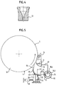
- FIG. 5 shows analogously to the representation according to FIG. 1 a schematic, much simplified side Sectional view of an essential portion of a Device according to the invention according to a second Embodiment.
- This variant is a device for indirect application of a liquid or pasty Application medium 2 designed on an application roller 32, wherein the circumference of the rotating applicator roller 32 that of the Single application nozzles 12 with the application medium 2 acted upon running surface 4 forms.
- the coating the material web itself then takes place in a nip, through which the material web runs and in which the Application medium 2 from the one serving as the carrier surface Roll surface 4 is transferred to the material web.
- the Material web and the nip as well as their arrangement are in the drawing for clarity not shown and may be assumed to be known as such.
- the Distribution tube 10 is in this example as a double wall Component made of a material with non-stick properties, namely a carbon fiber composite, manufactured, wherein an inner tube 10.2 the feed channel for the application medium 2 and the outer tube jacket 10.4 a channel for cooling water 34th forms.
- the single application nozzles 12 are as through the body of the distribution pipe 10 passing narrow, slit-like Outflow channels with a substantially rectangular Passage cross section designed and act as Flat fan nozzles that have a thin, fanned out Generate flat jet 18 of application medium 2.
- nozzle jet deflection device 36 which deflects the respective jet jet 18 of the application medium 2 emerging from a respective flat jet nozzle 12 in the direction of the running surface 4 .
- all flat jet nozzles 12 are assigned a common jet deflection device 36, which extends essentially over the entire width of the application roller 32.
- the nozzle jet deflection device is designed here as a concave baffle plate 36.
- the baffle 36 can of course have other suitable shape.
- the baffle plate 36 can be flat or can be concave or convex curved.
- the drawing also shows that the baffle plate 36 is arranged at a distance D1 from the flat jet nozzles 12.
- the distance between the nozzle outlet opening and the impact area on the baffle plate 36 is identified by the reference symbol D2.
- the nozzle jet 18 is deflected in the direction of the running surface 4 and leaves the baffle plate 36 again at its upper free end in order to then move over a further section through the free ambient atmosphere to the surface 4 to be coated.
- the nozzle jet leaving the baffle plate 36 which, as will be explained in more detail below, has special properties, is identified here with the reference symbol 18 L.
- the invention is not restricted to the values mentioned above. Depending on the application and type of the individual application nozzles used and the respective jet deflection device, a modification according to the invention can deviate considerably from this data.
- the distance is not fixed, but can be set variably.
- the arrangement of the nozzle jet deflection device 36 that is to say the baffle plate 36, is adjustable relative to the flat jet nozzles 12.
- the baffle plate 36 is fastened on a holder 38 which can be moved in a predetermined distance range from the flat jet nozzles 12.
- This holder 38 can be moved toward and away from the flat jet nozzles 12 by means of a plurality of first actuators 40, which are spaced apart from one another in the width direction of the application roller 32 and act on the holder 38 (indicated by double arrows in FIG. 5).
- the baffle plate 36 is also pivotally mounted on the holder 38 via an axis 42 and is arranged relative to the flat jet nozzles 12 and the running surface by means of a plurality of second actuators 44 which are spaced apart from one another in the width direction of the application roller 32 and act on the baffle plate 36 and the holder 38 4 swiveling. In this way, the angle of incidence of the flat jets 18 on the baffle plate 36 and the angle of incidence of the jet jet 18 L leaving the baffle plate 36 on the running surface 4 can be adjusted.
- the flapper 36 also has some flexibility owns, both by evenly pressing all first actuators 40 over substantially the entire Applicator roller width uniform change of the distance as well as by actuating only certain first actuators 40 a locally different change in the distance be achieved.
- an even one allows Actuate all second actuators 44 one in the essentially the entire application roller width is uniform Change the impact angle during an actuation only certain second actuators 44 one locally causes different changes in the impact angle. It it can be seen that in this way not only the location of the Baffle plate 36 with respect to the flow direction of the Jet streams 18 but also the geometry of the jet stream deflecting device 36 can be manipulated.
- the nozzle jet deflecting device on the one hand brings about an equalization of the nozzle jets 18, it thus functions simultaneously as a nozzle jet equalizing device arranged between the individual application nozzles 12 and the running surface 4, and on the other hand a certain delay or two-dimensional extension or spreading of the Nozzle jets 18. It has been shown that surprisingly, laminar individual jets or flat jets 18 L can be generated in this way, which not only can be localized relatively precisely, but which also have a very even distribution of the application medium due to the interference of the respective individual jets 18 L 2 enable on the current surface 4.
- the incident or incident angle of the nozzle jet 18 of the liquid or pasty application medium 2 on the nozzle jet deflection device determine the degree of the resulting jet extension, ie the angle of propagation of the laminar flat jet 18 L generated.
- the excess Order medium 2 is made with the help of a the order location downstream doctor element 14, here: a rotating smooth roll doctor bar with approx. 35 mm diameter, doctored and returned to an order medium cycle, which by reference numeral 46 is indicated.
- the doctor blade stick 14 also serves as Leveling device, that on the running surface 4 applied application medium 2 evened out.
- Fig. 6a shows analogous to the representation of Fig. 1 and Fig. 5 is a schematic side sectional view of a essential part of a device according to the invention according to a third embodiment.
- the device 5 also has this model between the Flat jet nozzles 12 and the running surface 4 arranged and again as a baffle-like construction trained jet deflector 48.
- the jet deflecting device 48 immediately in front of the nozzle outlet openings of the Flat jet nozzles 12 is arranged and one of the Nozzle outlet opening in the direction of the one to be coated Surface 4 extending guide surface 48.2 for the respective jet 18 of the emerging from a nozzle Order medium 2 forms.
- the jet deflection device 48 here is a lip-like extension of the Flat jet nozzles 12. On the exact design of this special nozzle jet deflection device 48 will follow be discussed in more detail.
- the distribution pipe 10 has a rectangular cross-sectional shape in the present case. Narrow and essentially rectangular (round, oval or other suitable shapes are possible) discharge bores designed as single application nozzles 12 are provided on the intersection between two wall sections of the distribution pipe 10 which are perpendicular to one another. In cooperation with the nozzle jet deflection device 48, these outflow bores largely have the properties of flat jet nozzles, that is to say they each produce a flat, fanned-out jet jet 18 L (see also FIG. 6 b).
- each individual application nozzle 12 is shown (in FIG. 6b only two adjacent nozzles are shown for reasons of clarity, which are designated 12a and 12b for better distinction) are assigned their own separate nozzle jet deflection device 48 (here: 48a and 48b).
- the latter device is in each case a baffle plate fastened to an outer wall of the rectangular distribution pipe 10, which, however, is referred to as baffle strip 48 in the context of the present description for better differentiation from the baffle plate 36 mentioned above.
- the baffle bar 48 has a guide surface section 48.2, which adjoins the nozzle outlet opening of the individual application nozzle 12 in a fluidically favorable manner.
- the nozzle jet 18 leaving the outlet opening of a respective individual application nozzle 12 thus flows directly onto the guide surface section 48.2 of the baffle strip 48 and along this section 48.2, is deflected in the direction of the roller 32 and leaves the guide surface section 48.2 and thus the baffle strip 48 (here : 48a and 48b) at their upper free end as a narrow, fanned laminar flat jet 18 L.
- the laminar flat jet 18 L then runs a certain distance through the free ambient atmosphere and then strikes the surface 4 of the roller 32. As indicated in FIG.
- the respectively adjacent nozzle jet deflection devices or baffle strips 48a, 48b are offset arranged in relation to each other, so that the adjacent fanned flat jets 18 L emanating from the adjacent individual application nozzles 12a and 12b (hereinafter analogous to the two nozzles 12a, 12b considered here and their respective jet deflection devices 48a and 48b with 18a L and 18b L denotes) of the application medium 2 on their way to the surface 4 to be coated, do not touch or penetrate.
- the offset V is therefore expediently greater than or equal to the thickness of the respective flat beams 18a L , 18b L.
- the fanned flat beams 18a L , 18b L and partial areas of the adjacent baffle strips 48a, 48b are shown folded into the viewing plane for illustrative purposes.
- the lines of incidence La, Lb of the adjacent flat beams 18a L , 18b L are also drawn into the image plane. It can be seen that the distance Va of the impact lines La, Lb measured in the running direction of the surface 4 approximately corresponds to the offset V of the baffle strips 48a, 48b if, as assumed here, the orientations of the baffle strips 48a, 48b relative to the surface 4 and thus the In the lateral direction, the radiation angles (similar to ⁇ in FIG. 1) of the flat beams 18a L , 18b L relative to the surface 4 are the same.
- the distance Va can be changed, for example, by varying the aforementioned parameters, Va can also become 0, ie the flat beams 18a L , 18b L then penetrate each other when they strike the surface 4 at a common line of incidence.
- the adjacent individual application areas generated by such a configuration of the individual application nozzles 12 and their associated nozzle jet deflection devices 48a, 48b can at least partially penetrate (U) in their respective edge regions due to the overlay effect resulting from the movement of the running surface 4, so that As the running surface 4 progresses, a closed application medium layer can be produced over essentially the entire width of the surface 4 to be coated.
- This Device comprises several, i.e. in the present case two, a running material web 4 in the width direction B extensive and from a variety of single application nozzles 12 (each facing the material web 4 and in the figure indicated by circles) formed nozzle rows R1, R2, which in Longitudinal direction of the material web 4, that of the in the drawing direction of progress indicated by an arrow Material web 4 corresponds to, are spaced.
- the row of nozzles R1 runs essentially parallel to Width direction B, while the nozzle row R2 is in one Angle ⁇ extends to the width direction B.
- the invention is not limited to the above embodiments, which is only the general explanation of the basic idea serve the invention, limited. Within the scope of protection can the inventive method and device according to the invention rather than that Assume the embodiments described above.
- the method and the device can in particular Features that are a combination of the respective Represent individual features of the associated claims.
- the device can also have one or more Application nozzles upstream of doctor blades or Have cleaning doctor devices and the like.
- the invention provides the application medium by two or more in the width direction of the Surface and / or extending at an angle to it the individual application nozzles formed rows of nozzles, each are spaced apart in the longitudinal direction of the surface, to be applied, differing from the individual rows of nozzles ejected individual quantities of the application medium during the Progression of the current surface to one Total required total order quantity.
- the order can also be used here either without or with Surplus.
- the invention also includes such a variant in which one separate jet deflection device only for certain Flat jet nozzles from the total number of available Flat jet nozzles is provided. Otherwise, the on the length of the jet deflecting device relative to the jet direction be variably adjustable. It is also through a specific local length specification of the jet deflection device their effect on the jet influenceable.
Applications Claiming Priority (2)
| Application Number | Priority Date | Filing Date | Title |
|---|---|---|---|
| DE19722159A DE19722159A1 (de) | 1997-05-27 | 1997-05-27 | Verfahren und Vorrichtung zum direkten oder indirekten Auftragen eines flüssigen oder pastösen Auftragsmediums auf eine laufende Oberfläche |
| DE19722159 | 1997-05-27 |
Publications (3)
| Publication Number | Publication Date |
|---|---|
| EP0881330A2 true EP0881330A2 (fr) | 1998-12-02 |
| EP0881330A3 EP0881330A3 (fr) | 1999-10-13 |
| EP0881330B1 EP0881330B1 (fr) | 2002-11-06 |
Family
ID=7830632
Family Applications (1)
| Application Number | Title | Priority Date | Filing Date |
|---|---|---|---|
| EP98109532A Expired - Lifetime EP0881330B1 (fr) | 1997-05-27 | 1998-05-26 | Procédé et dispositif pour enduire un matériau fluide ou pâteux sur une bande en mouvement |
Country Status (7)
| Country | Link |
|---|---|
| US (3) | US6063450A (fr) |
| EP (1) | EP0881330B1 (fr) |
| JP (1) | JPH10328585A (fr) |
| AT (1) | ATE227376T1 (fr) |
| BR (1) | BR9802994A (fr) |
| CA (1) | CA2238846A1 (fr) |
| DE (2) | DE19722159A1 (fr) |
Cited By (8)
| Publication number | Priority date | Publication date | Assignee | Title |
|---|---|---|---|---|
| EP0949380A2 (fr) * | 1998-04-11 | 1999-10-13 | Voith Sulzer Papiertechnik Patent GmbH | Dispositif pour enduire directement ou indirectement une ou deux faces d'une surface en mouvement avec un matériau fluide ou pâteux |
| WO2000018514A1 (fr) * | 1998-09-30 | 2000-04-06 | Voith Sulzer Papiertechnik Patent Gmbh | Procede et dispositif pour appliquer une substance liquide ou pateuse sur un substrat en mouvement |
| WO2000042254A1 (fr) * | 1999-01-18 | 2000-07-20 | Metso Paper, Inc. | Procede de couchage par pulverisation et dispositif de couchage par pulverisation |
| EP1050622A2 (fr) * | 1999-05-07 | 2000-11-08 | Voith Sulzer Papiertechnik Patent GmbH | Dispositif et procédé d'application pour une machine à papier |
| EP1253241A2 (fr) | 2001-04-27 | 2002-10-30 | Giesecke & Devrient GmbH | Procédé et dispositif pour insérer des éléments de sécurité dans une bande de papier |
| EP1759846A1 (fr) * | 2005-08-10 | 2007-03-07 | Oxy-Dry Maschinen GmbH | Buse de matière élastique souple |
| WO2008151943A1 (fr) * | 2007-06-13 | 2008-12-18 | Voith Patent Gmbh | Dispositif racleur |
| EP3332955A1 (fr) * | 2016-12-08 | 2018-06-13 | Valmet Aktiebolag | Dispositif de pulvérisation d'un revêtement chimique sur une surface mobile d'une machine à papier |
Families Citing this family (32)
| Publication number | Priority date | Publication date | Assignee | Title |
|---|---|---|---|---|
| DE19722159A1 (de) * | 1997-05-27 | 1998-12-03 | Voith Sulzer Papiermasch Gmbh | Verfahren und Vorrichtung zum direkten oder indirekten Auftragen eines flüssigen oder pastösen Auftragsmediums auf eine laufende Oberfläche |
| DE19844979A1 (de) * | 1997-05-27 | 2000-04-06 | Voith Sulzer Papiermasch Gmbh | Verfahren zum direkten oder indirekten Auftragen eines flüssigen oder pastösen Auftragmediums auf eine laufende Oberfläche |
| DE19844023A1 (de) * | 1998-09-25 | 2000-04-20 | Alcatel Sa | Vorrichtung zum Beschichten einer optischen Faser |
| FI108993B (fi) * | 1999-06-30 | 2002-05-15 | Metso Paper Inc | Menetelmä ja sovitelma käsittelyaineen levittämiseksi liikkuvalle pinnalle |
| US20020192360A1 (en) * | 2001-04-24 | 2002-12-19 | 3M Innovative Properties Company | Electrostatic spray coating apparatus and method |
| JP2002235272A (ja) * | 2001-02-02 | 2002-08-23 | Tsudakoma Corp | 経糸糊付け機 |
| FI20010985A0 (fi) * | 2001-05-10 | 2001-05-10 | Metso Paper Inc | Menetelmä ja sovitelma paperin tai kartongin käsittelemiseksi |
| FI115149B (fi) * | 2001-08-03 | 2005-03-15 | Corenso United Oy Ltd | Menetelmä ja laitteisto sideaineen annostelemiseksi |
| FI111870B (fi) * | 2002-01-15 | 2003-09-30 | Metso Paper Inc | Suutinryhmä |
| FI111562B (fi) * | 2002-01-16 | 2003-08-15 | Metso Paper Inc | Menetelmä ja laitteisto käsittelyaineen syöttämiseksi liikkuvalle pinnalle |
| EP1396286B1 (fr) * | 2002-09-06 | 2006-03-22 | Lactec Gesellschaft für moderne Lackiertechnik mbH | Dispositif pour appliquer matière de revêtement liquide, spécialement une feuille liquide |
| DE10241222B4 (de) * | 2002-09-06 | 2006-04-13 | LacTec Gesellschaft für moderne Lacktechnik GmbH | Vorrichtung zum Auftragen eines flüssigen Beschichtungsmaterials, insbesondere einer Flüssigfolie |
| FI113884B (fi) * | 2002-09-26 | 2004-06-30 | Metso Paper Inc | Suutin |
| US8545574B2 (en) * | 2003-06-17 | 2013-10-01 | The Procter & Gamble Company | Methods for treating fibrous structures |
| DE10343038A1 (de) * | 2003-09-16 | 2005-04-07 | Voith Paper Patent Gmbh | Auftragsverfahren |
| DE10343021A1 (de) * | 2003-09-16 | 2005-04-07 | Voith Paper Patent Gmbh | Auftragsverfahren |
| SE526978C2 (sv) * | 2004-04-20 | 2005-11-29 | Metso Paper Karlstad Ab | Skyddsanordning för sprayutrustning och sätt att skydda denna och dess omgivning |
| US20060266485A1 (en) * | 2005-05-24 | 2006-11-30 | Knox David E | Paper or paperboard having nanofiber layer and process for manufacturing same |
| JP2009517213A (ja) * | 2005-12-01 | 2009-04-30 | スリーエム イノベイティブ プロパティズ カンパニー | 多成分液体噴霧システム |
| US20070125877A1 (en) * | 2005-12-01 | 2007-06-07 | 3M Innovative Properties Company | Multi-component liquid spray systems |
| US20070125886A1 (en) * | 2005-12-01 | 2007-06-07 | 3M Innovative Properties Company | Methods of spraying multi-component liquids |
| US20070148365A1 (en) * | 2005-12-28 | 2007-06-28 | Knox David E | Process and apparatus for coating paper |
| DE102006028258A1 (de) * | 2006-06-20 | 2007-12-27 | Abb Patent Gmbh | Verfahren zur Ermittlung von Sprühparametern zur Steuerung eines Sprühmittel einsetzenden Lackiergeräts |
| EP2391459B1 (fr) * | 2009-02-02 | 2014-08-06 | Siemens Vai Metals Technologies SAS | Methode et dispositif d'arrosage d'une installation de laminage |
| DE102010029815A1 (de) | 2010-06-08 | 2011-12-08 | Voith Patent Gmbh | Verfahren und Vorrichtung zum ein- oder beidseitigen Auftragen eines flüssigen oder pastösen Auftragsmediums in Form wenigstens eines Sprühstrahles |
| WO2011159276A1 (fr) | 2010-06-15 | 2011-12-22 | 3M Innovative Properties Company | Collecteur de distribution à aiguilles de distribution multiples |
| US8985051B2 (en) * | 2011-12-15 | 2015-03-24 | Honeywell Asca Inc. | Apparatus for producing a spray of changed droplets of aqueous liquid |
| CN102886981A (zh) * | 2012-10-15 | 2013-01-23 | 北京印刷学院 | 一种用于橡皮滚筒清洗装置的喷洒机构及其喷嘴 |
| EP2868802A1 (fr) * | 2013-10-31 | 2015-05-06 | Valmet Technologies, Inc. | Agencement dans une ligne de production de toile fibreuse et procédé associé |
| WO2017077696A1 (fr) * | 2015-11-06 | 2017-05-11 | 三洋電機株式会社 | Procédé permettant de fabriquer une plaque d'électrode pour des appareils de stockage d'énergie et appareil de revêtement |
| IT201700056951A1 (it) * | 2017-05-25 | 2018-11-25 | Biesse Spa | Macchina per la bordatura di pannelli di legno o simili |
| EP3842591A1 (fr) | 2019-12-23 | 2021-06-30 | Andritz Küsters GmbH | Dispositif d'application d'un milieu d'application |
Citations (10)
| Publication number | Priority date | Publication date | Assignee | Title |
|---|---|---|---|---|
| DE1546280A1 (de) * | 1964-04-17 | 1970-02-26 | Fr Des Silicates Speciaux Sifr | Verfahren zum Fuellen von Papier |
| DE1611787A1 (de) * | 1967-01-05 | 1971-03-25 | Ransburg Electro Coating Corp | Verfahren und Vorrichtung zur Herstellung von Papier und aehnlichen Zellulosematerialien durch elektrostatischen Auftrag von fluessigen Staerkedispersionen auf eine fortbewegte wasserhaltige Bahn |
| DE2054752A1 (de) * | 1969-11-07 | 1971-05-13 | Tunzini Sames, Grenoble (Frankreich) | Verfahren und Fertigungsanlage zur Herstellung einer klebfahigen Papierbahn |
| DE1761858A1 (de) * | 1968-07-15 | 1971-10-28 | Feldmuehle Ag | Vorrichtung zum Beschichten oder Impraegnieren von flaechigen Bahnen |
| EP0373276A1 (fr) * | 1987-11-04 | 1990-06-20 | Ogilvie Aquitaine S.A. | Procédé et dispositif de pulvérisation continue d'adjuvants sur des produits perméables en bande lors de leur défilement |
| EP0421262A2 (fr) * | 1989-09-30 | 1991-04-10 | ATOTECH Deutschland GmbH | Procédé de traitement d'objets avec un fluide et dispositif de mise en oeuvre de ce procédé |
| DE4205313A1 (de) * | 1992-02-21 | 1993-08-26 | Voith Gmbh J M | Duesenauftragswerk zum auftragen von streichfarbe auf eine papierbahn |
| DE29506334U1 (de) * | 1995-04-12 | 1996-08-14 | Itw Dynatec Gmbh Klebetechnik | Vorrichtung zum Auftragen von Leim o.dgl. und dafür geeignete Düsenplatte |
| DE19504652A1 (de) * | 1995-02-13 | 1996-08-14 | Kotterer Grafotec | Vorrichtung zur Erzeugung eines Flüssigkeitsstrahls |
| WO1997013035A1 (fr) * | 1995-10-05 | 1997-04-10 | Valmet Corporation | Procede et dispositif servant a effectuer le revetement d'une bande de papier ou de carton en deplacement |
Family Cites Families (40)
| Publication number | Priority date | Publication date | Assignee | Title |
|---|---|---|---|---|
| US2733172A (en) * | 1956-01-31 | Apparatus and method of producing | ||
| US1662641A (en) * | 1927-02-21 | 1928-03-13 | Container Corp | Process for sizing paper |
| US2130241A (en) * | 1934-06-18 | 1938-09-13 | Seaman Paper Company | Method for coating paper |
| US2233122A (en) * | 1938-02-28 | 1941-02-25 | United States Gypsum Co | Method and apparatus for manufacturing roofing materials |
| US2236526A (en) * | 1938-08-30 | 1941-04-01 | Du Pont | Nonfibrous structure and method for preparing same |
| US2839425A (en) * | 1951-03-13 | 1958-06-17 | Apparatus and method of coating articles | |
| DE1184287B (de) * | 1957-04-18 | 1964-12-23 | Davy & United Eng Co Ltd | Duese zum Erzeugen eines flachen Schmieroelstrahls, insbesondere fuer die Bearbeitung von Blechbahnen |
| US3056416A (en) * | 1958-07-11 | 1962-10-02 | Nat Res Dev | Control means for fluid pressure systems |
| US3152918A (en) * | 1961-06-02 | 1964-10-13 | Kimberly Clark Co | Process of coating paper with a trailing blade |
| US3333570A (en) * | 1964-10-09 | 1967-08-01 | Jens A Paasche | Anti-ink offset powder assembly |
| GB1382828A (en) * | 1971-04-02 | 1975-02-05 | Plessey Co Ltd | Liquidspraying devices having a nozzle subjected to high-frequency vibrations |
| GB1430231A (en) * | 1972-02-17 | 1976-03-31 | Kennedy Engs Ltd | Retention of strip material in an uncreased condition |
| US3885066A (en) * | 1972-11-24 | 1975-05-20 | Ppg Industries Inc | Method for coating continuously advancing substrate |
| US4064295A (en) * | 1973-11-06 | 1977-12-20 | National Research Development Corporation | Spraying atomized particles |
| US3998084A (en) * | 1974-11-01 | 1976-12-21 | Marotta Scientific Controls, Inc. | Cooling spray system for rolling mill |
| US4088093A (en) * | 1976-04-13 | 1978-05-09 | Continental Can Company, Inc. | Web coating and powder feed |
| DE2731799C3 (de) * | 1977-07-14 | 1984-10-18 | Reich Spezialmaschinen GmbH, 7440 Nürtingen | Kantenanleimmaschine mit einer Schmelzkammer |
| DE3024564A1 (de) * | 1980-06-28 | 1982-02-04 | Veba-Glas Ag, 4300 Essen | Verfahren und vorrichtung zum beschichten der aussenflaechen von glasflaschen |
| EP0102765B1 (fr) * | 1982-08-20 | 1986-11-12 | British United Shoe Machinery Limited | Buse d'application |
| FI75285C (fi) * | 1983-02-21 | 1988-07-08 | Jagenberg Ag | Anordning foer belaeggning av loepande materialbanor. |
| US4524716A (en) * | 1984-01-18 | 1985-06-25 | Appleton Papers Inc. | Adjustable air knife |
| JPS60183067A (ja) * | 1984-03-02 | 1985-09-18 | Honda Motor Co Ltd | 塗装方法 |
| US4601727A (en) * | 1984-08-13 | 1986-07-22 | Rca Corporation | Textile dyeing process and apparatus for multicolor patterns |
| DE8520129U1 (fr) * | 1985-07-12 | 1987-02-19 | Hoechst Ag, 6230 Frankfurt, De | |
| ES2029264T3 (es) * | 1987-07-21 | 1992-08-01 | Agfa-Gevaert Naamloze Vennootschap | Metodo de revestimiento. |
| DE3734097A1 (de) * | 1987-10-09 | 1989-04-27 | Du Pont Deutschland | Verfahren und vorrichtung zum behandeln eines photographischen aufzeichnungsmaterials |
| DE4000405A1 (de) * | 1990-01-09 | 1991-07-11 | Hoechst Ag | Verfahren und vorrichtung zum gleichmaessigen aufbringen eines fluids auf eine bewegte materialbahn |
| DE4013322A1 (de) * | 1990-04-26 | 1991-10-31 | Heino Kaiser | Mehrfach-auftragskopf |
| JP2532323Y2 (ja) * | 1990-10-26 | 1997-04-16 | 株式会社いけうち | ノズル |
| GB2250935B (en) * | 1990-12-04 | 1994-02-23 | Marshall Welded Steel Limited | Automatic sprayer apparatus |
| EP0489978B1 (fr) * | 1990-12-12 | 1996-03-20 | Agfa-Gevaert N.V. | Enduiseuse à rideau |
| DE9100980U1 (fr) * | 1991-01-29 | 1992-05-27 | Eduard Kuesters Maschinenfabrik Gmbh & Co Kg, 4150 Krefeld, De | |
| DE4337438C2 (de) * | 1993-11-03 | 1996-03-14 | Schiele Josef | Verfahren zum Durchlauf-Vakuum-Rundumbeschichten und Vakuum-Durchlauf-Rundum-Beschichtungskammer zur Durchführung des Verfahrens |
| DE4412084C1 (de) * | 1994-04-08 | 1996-01-11 | Fraunhofer Ges Forschung | Werkstückträger zur Verwendung bei elektrostatischen Beschichtungsverfahren |
| US5622599A (en) * | 1994-06-28 | 1997-04-22 | Sproule; Barry | Method and apparatus for coating pulp products |
| US5849321A (en) * | 1994-07-01 | 1998-12-15 | Valmet Corporation | Method and apparatus for spray-coating a paper or board web |
| US5557307A (en) * | 1994-07-19 | 1996-09-17 | Moore Business Forms, Inc. | Continuous cleaning thread for inkjet printing nozzle |
| DE19527501A1 (de) * | 1995-07-27 | 1997-01-30 | Linde Ag | Verfahren und Vorrichtung zum Beschichten eines Gegenstandes |
| EP0761877A3 (fr) * | 1995-09-06 | 1997-06-25 | Voith Sulzer Papiermasch Gmbh | Dispositif d'application directe ou indirecte de matériau fluide ou pâteux sur une bande en mouvement, en particulier de papier ou carton |
| DE19722159A1 (de) * | 1997-05-27 | 1998-12-03 | Voith Sulzer Papiermasch Gmbh | Verfahren und Vorrichtung zum direkten oder indirekten Auftragen eines flüssigen oder pastösen Auftragsmediums auf eine laufende Oberfläche |
-
1997
- 1997-05-27 DE DE19722159A patent/DE19722159A1/de not_active Withdrawn
-
1998
- 1998-05-26 CA CA002238846A patent/CA2238846A1/fr not_active Abandoned
- 1998-05-26 AT AT98109532T patent/ATE227376T1/de active
- 1998-05-26 US US09/084,727 patent/US6063450A/en not_active Expired - Lifetime
- 1998-05-26 JP JP10144021A patent/JPH10328585A/ja active Pending
- 1998-05-26 EP EP98109532A patent/EP0881330B1/fr not_active Expired - Lifetime
- 1998-05-26 DE DE59806147T patent/DE59806147D1/de not_active Expired - Lifetime
- 1998-05-27 BR BR9802994-0A patent/BR9802994A/pt not_active IP Right Cessation
-
2000
- 2000-05-15 US US09/571,104 patent/US6494954B1/en not_active Expired - Fee Related
- 2000-05-15 US US09/570,822 patent/US6410100B1/en not_active Expired - Fee Related
Patent Citations (10)
| Publication number | Priority date | Publication date | Assignee | Title |
|---|---|---|---|---|
| DE1546280A1 (de) * | 1964-04-17 | 1970-02-26 | Fr Des Silicates Speciaux Sifr | Verfahren zum Fuellen von Papier |
| DE1611787A1 (de) * | 1967-01-05 | 1971-03-25 | Ransburg Electro Coating Corp | Verfahren und Vorrichtung zur Herstellung von Papier und aehnlichen Zellulosematerialien durch elektrostatischen Auftrag von fluessigen Staerkedispersionen auf eine fortbewegte wasserhaltige Bahn |
| DE1761858A1 (de) * | 1968-07-15 | 1971-10-28 | Feldmuehle Ag | Vorrichtung zum Beschichten oder Impraegnieren von flaechigen Bahnen |
| DE2054752A1 (de) * | 1969-11-07 | 1971-05-13 | Tunzini Sames, Grenoble (Frankreich) | Verfahren und Fertigungsanlage zur Herstellung einer klebfahigen Papierbahn |
| EP0373276A1 (fr) * | 1987-11-04 | 1990-06-20 | Ogilvie Aquitaine S.A. | Procédé et dispositif de pulvérisation continue d'adjuvants sur des produits perméables en bande lors de leur défilement |
| EP0421262A2 (fr) * | 1989-09-30 | 1991-04-10 | ATOTECH Deutschland GmbH | Procédé de traitement d'objets avec un fluide et dispositif de mise en oeuvre de ce procédé |
| DE4205313A1 (de) * | 1992-02-21 | 1993-08-26 | Voith Gmbh J M | Duesenauftragswerk zum auftragen von streichfarbe auf eine papierbahn |
| DE19504652A1 (de) * | 1995-02-13 | 1996-08-14 | Kotterer Grafotec | Vorrichtung zur Erzeugung eines Flüssigkeitsstrahls |
| DE29506334U1 (de) * | 1995-04-12 | 1996-08-14 | Itw Dynatec Gmbh Klebetechnik | Vorrichtung zum Auftragen von Leim o.dgl. und dafür geeignete Düsenplatte |
| WO1997013035A1 (fr) * | 1995-10-05 | 1997-04-10 | Valmet Corporation | Procede et dispositif servant a effectuer le revetement d'une bande de papier ou de carton en deplacement |
Cited By (17)
| Publication number | Priority date | Publication date | Assignee | Title |
|---|---|---|---|---|
| EP0949380A2 (fr) * | 1998-04-11 | 1999-10-13 | Voith Sulzer Papiertechnik Patent GmbH | Dispositif pour enduire directement ou indirectement une ou deux faces d'une surface en mouvement avec un matériau fluide ou pâteux |
| EP0949380A3 (fr) * | 1998-04-11 | 2000-06-07 | Voith Sulzer Papiertechnik Patent GmbH | Dispositif pour enduire directement ou indirectement une ou deux faces d'une surface en mouvement avec un matériau fluide ou pâteux |
| WO2000018514A1 (fr) * | 1998-09-30 | 2000-04-06 | Voith Sulzer Papiertechnik Patent Gmbh | Procede et dispositif pour appliquer une substance liquide ou pateuse sur un substrat en mouvement |
| WO2000042254A1 (fr) * | 1999-01-18 | 2000-07-20 | Metso Paper, Inc. | Procede de couchage par pulverisation et dispositif de couchage par pulverisation |
| US6627261B1 (en) | 1999-01-18 | 2003-09-30 | Metso Paper, Inc. | Spray-coating method and spray-coater |
| US6494988B1 (en) | 1999-05-07 | 2002-12-17 | Voith Sulzer Papiertechnik Patent Gmbh | Process for improving the surface of offset paper |
| EP1050622A3 (fr) * | 1999-05-07 | 2001-08-16 | Voith Paper Patent GmbH | Dispositif et procédé d'application pour une machine à papier |
| EP1050622A2 (fr) * | 1999-05-07 | 2000-11-08 | Voith Sulzer Papiertechnik Patent GmbH | Dispositif et procédé d'application pour une machine à papier |
| EP1253241A2 (fr) | 2001-04-27 | 2002-10-30 | Giesecke & Devrient GmbH | Procédé et dispositif pour insérer des éléments de sécurité dans une bande de papier |
| DE10120818A1 (de) * | 2001-04-27 | 2002-10-31 | Giesecke & Devrient Gmbh | Verfahren und Vorrichtung zum Einbringen von Merkmalsstoffen in eine Papierbahn |
| EP1253241A3 (fr) * | 2001-04-27 | 2004-02-04 | Giesecke & Devrient GmbH | Procédé et dispositif pour insérer des éléments de sécurité dans une bande de papier |
| EP1759846A1 (fr) * | 2005-08-10 | 2007-03-07 | Oxy-Dry Maschinen GmbH | Buse de matière élastique souple |
| US7644659B2 (en) | 2005-08-10 | 2010-01-12 | Oxy-Dry Maschinen Gmbh | Cleaning apparatus for cylinder surfaces of a printing machine and spray nozzle for such a cleaning apparatus |
| WO2008151943A1 (fr) * | 2007-06-13 | 2008-12-18 | Voith Patent Gmbh | Dispositif racleur |
| EP3332955A1 (fr) * | 2016-12-08 | 2018-06-13 | Valmet Aktiebolag | Dispositif de pulvérisation d'un revêtement chimique sur une surface mobile d'une machine à papier |
| CN108177394A (zh) * | 2016-12-08 | 2018-06-19 | 维美德股份公司 | 用于将化学涂料喷涂到造纸机的移动表面上的装置 |
| CN108177394B (zh) * | 2016-12-08 | 2020-12-18 | 维美德股份公司 | 用于将化学涂料喷涂到造纸机的移动表面上的装置 |
Also Published As
| Publication number | Publication date |
|---|---|
| DE59806147D1 (de) | 2002-12-12 |
| EP0881330B1 (fr) | 2002-11-06 |
| CA2238846A1 (fr) | 1998-11-27 |
| JPH10328585A (ja) | 1998-12-15 |
| EP0881330A3 (fr) | 1999-10-13 |
| US6063450A (en) | 2000-05-16 |
| BR9802994A (pt) | 1999-11-03 |
| DE19722159A1 (de) | 1998-12-03 |
| US6494954B1 (en) | 2002-12-17 |
| ATE227376T1 (de) | 2002-11-15 |
| US6410100B1 (en) | 2002-06-25 |
Similar Documents
| Publication | Publication Date | Title |
|---|---|---|
| EP0881330B1 (fr) | Procédé et dispositif pour enduire un matériau fluide ou pâteux sur une bande en mouvement | |
| DE19718773B4 (de) | Lackierkopf | |
| AT505228B1 (de) | Verfahren und vorrichtung zum behandeln einer faserbahn | |
| EP2183057A2 (fr) | Procédé et dispositif d'application de revêtements plastiques | |
| EP0928845A2 (fr) | Dispositif pour appliquer un liquide ou un produit pâteux sur une bande en mouvement, particulièrement de papier ou de carton | |
| DE10131680A1 (de) | Auftragsvorrichtung | |
| EP1516087B2 (fr) | Dispositif d'enduction des deux faces d'une bande notamment de papier ou de carton et de sechage de cette bande | |
| DE19634448C2 (de) | Verfahren und Vorrichtung zum Auftragen eines flüssigen oder pastösen Mediums auf eine laufende Materialbahn | |
| DE19921592A1 (de) | Applikationsvorrichtung und -verfahren für eine Papiermaschine | |
| EP2157240A2 (fr) | Dispositif d'application de rideau | |
| EP1782891B1 (fr) | Méthode et appareil pour le dépôt d'au moins deux couches de peinture sur la surface d'une bande continue, en particulier d'une bande continue de papier ou de carton | |
| DE10232949A1 (de) | Vorhang-Auftragsvorrichtung | |
| EP2146003A2 (fr) | Unité d'application de rideau | |
| EP0855464A2 (fr) | Dispositif et méthode d'enduction directe ou indirecte d'une substance liquide ou pâteuse ssur une bande en mouvement | |
| DE10012345A1 (de) | Vorhang-Auftragsvorrichtung | |
| DE10057731A1 (de) | Vorhang-Auftragsvorrichtung | |
| DE102009000639A1 (de) | Verfahren zum Beschichten eines Bandes, insbesondere einer Papiermaschinenbespannung | |
| WO2006069904A2 (fr) | Procede et dispositif pour traiter une bande de papier, carton ou autre matiere fibreuse en mouvement | |
| EP1375746B1 (fr) | Procédé et dispositif pour enduire une ou deux faces avec un matériau fluide jusqu' au pâteux | |
| DE19743246A1 (de) | Kombinations-Auftragsvorrichtung | |
| DE102015014715A1 (de) | Vorrichtung und Verfahren zur Bepuderung von Druckbogen | |
| WO2000018514A1 (fr) | Procede et dispositif pour appliquer une substance liquide ou pateuse sur un substrat en mouvement | |
| DE102010029815A1 (de) | Verfahren und Vorrichtung zum ein- oder beidseitigen Auftragen eines flüssigen oder pastösen Auftragsmediums in Form wenigstens eines Sprühstrahles | |
| DE19960772A1 (de) | Auftragsverfahren | |
| DE1575043C3 (de) | Strömungsmitteldüse mit Stellvorrichtung für Streich- und Beschichtungsmaschinen |
Legal Events
| Date | Code | Title | Description |
|---|---|---|---|
| PUAI | Public reference made under article 153(3) epc to a published international application that has entered the european phase |
Free format text: ORIGINAL CODE: 0009012 |
|
| AK | Designated contracting states |
Kind code of ref document: A2 Designated state(s): AT DE FI FR IT SE |
|
| AX | Request for extension of the european patent |
Free format text: AL;LT;LV;MK;RO;SI |
|
| PUAL | Search report despatched |
Free format text: ORIGINAL CODE: 0009013 |
|
| AK | Designated contracting states |
Kind code of ref document: A3 Designated state(s): AT BE CH CY DE DK ES FI FR GB GR IE IT LI LU MC NL PT SE |
|
| AX | Request for extension of the european patent |
Free format text: AL;LT;LV;MK;RO;SI |
|
| RIC1 | Information provided on ipc code assigned before grant |
Free format text: 6D 21H 23/50 A, 6B 05B 1/26 B, 6B 05B 5/14 B, 6D 21H 19:66 Z |
|
| RAP1 | Party data changed (applicant data changed or rights of an application transferred) |
Owner name: VOITH SULZER PAPIERTECHNIK PATENT GMBH |
|
| 17P | Request for examination filed |
Effective date: 20000211 |
|
| AKX | Designation fees paid |
Free format text: AT DE FI FR IT SE |
|
| RAP1 | Party data changed (applicant data changed or rights of an application transferred) |
Owner name: VOITH PAPER PATENT GMBH |
|
| 17Q | First examination report despatched |
Effective date: 20010307 |
|
| GRAG | Despatch of communication of intention to grant |
Free format text: ORIGINAL CODE: EPIDOS AGRA |
|
| RIC1 | Information provided on ipc code assigned before grant |
Free format text: 7D 21H 23/50 A, 7B 05B 1/26 B, 7B 05B 5/14 B, 7D 21H 19:66 Z |
|
| GRAG | Despatch of communication of intention to grant |
Free format text: ORIGINAL CODE: EPIDOS AGRA |
|
| GRAH | Despatch of communication of intention to grant a patent |
Free format text: ORIGINAL CODE: EPIDOS IGRA |
|
| GRAH | Despatch of communication of intention to grant a patent |
Free format text: ORIGINAL CODE: EPIDOS IGRA |
|
| GRAA | (expected) grant |
Free format text: ORIGINAL CODE: 0009210 |
|
| AK | Designated contracting states |
Kind code of ref document: B1 Designated state(s): AT DE FI FR IT SE |
|
| REF | Corresponds to: |
Ref document number: 227376 Country of ref document: AT Date of ref document: 20021115 Kind code of ref document: T |
|
| REF | Corresponds to: |
Ref document number: 59806147 Country of ref document: DE Date of ref document: 20021212 |
|
| ET | Fr: translation filed | ||
| PLBE | No opposition filed within time limit |
Free format text: ORIGINAL CODE: 0009261 |
|
| STAA | Information on the status of an ep patent application or granted ep patent |
Free format text: STATUS: NO OPPOSITION FILED WITHIN TIME LIMIT |
|
| 26N | No opposition filed |
Effective date: 20030807 |
|
| PGFP | Annual fee paid to national office [announced via postgrant information from national office to epo] |
Ref country code: SE Payment date: 20110513 Year of fee payment: 14 |
|
| PGFP | Annual fee paid to national office [announced via postgrant information from national office to epo] |
Ref country code: IT Payment date: 20110525 Year of fee payment: 14 |
|
| REG | Reference to a national code |
Ref country code: SE Ref legal event code: EUG |
|
| PG25 | Lapsed in a contracting state [announced via postgrant information from national office to epo] |
Ref country code: SE Free format text: LAPSE BECAUSE OF NON-PAYMENT OF DUE FEES Effective date: 20120527 Ref country code: IT Free format text: LAPSE BECAUSE OF NON-PAYMENT OF DUE FEES Effective date: 20120526 |
|
| PGFP | Annual fee paid to national office [announced via postgrant information from national office to epo] |
Ref country code: AT Payment date: 20120511 Year of fee payment: 15 |
|
| PGFP | Annual fee paid to national office [announced via postgrant information from national office to epo] |
Ref country code: FR Payment date: 20130603 Year of fee payment: 16 |
|
| REG | Reference to a national code |
Ref country code: AT Ref legal event code: MM01 Ref document number: 227376 Country of ref document: AT Kind code of ref document: T Effective date: 20140526 |
|
| PG25 | Lapsed in a contracting state [announced via postgrant information from national office to epo] |
Ref country code: AT Free format text: LAPSE BECAUSE OF NON-PAYMENT OF DUE FEES Effective date: 20140526 |
|
| REG | Reference to a national code |
Ref country code: FR Ref legal event code: ST Effective date: 20150130 |
|
| PG25 | Lapsed in a contracting state [announced via postgrant information from national office to epo] |
Ref country code: FR Free format text: LAPSE BECAUSE OF NON-PAYMENT OF DUE FEES Effective date: 20140602 |
|
| PGFP | Annual fee paid to national office [announced via postgrant information from national office to epo] |
Ref country code: DE Payment date: 20170523 Year of fee payment: 20 |
|
| PGFP | Annual fee paid to national office [announced via postgrant information from national office to epo] |
Ref country code: FI Payment date: 20170511 Year of fee payment: 20 |
|
| REG | Reference to a national code |
Ref country code: DE Ref legal event code: R071 Ref document number: 59806147 Country of ref document: DE |