EP0878110B1 - Reseau electronique synchronise comprenant des unites pilotes d'assistance - Google Patents
Reseau electronique synchronise comprenant des unites pilotes d'assistance Download PDFInfo
- Publication number
- EP0878110B1 EP0878110B1 EP96924415A EP96924415A EP0878110B1 EP 0878110 B1 EP0878110 B1 EP 0878110B1 EP 96924415 A EP96924415 A EP 96924415A EP 96924415 A EP96924415 A EP 96924415A EP 0878110 B1 EP0878110 B1 EP 0878110B1
- Authority
- EP
- European Patent Office
- Prior art keywords
- synchronizing signal
- synchronizing
- signals
- signal
- unit
- Prior art date
- Legal status (The legal status is an assumption and is not a legal conclusion. Google has not performed a legal analysis and makes no representation as to the accuracy of the status listed.)
- Expired - Lifetime
Links
Images


Classifications
-
- H—ELECTRICITY
- H04—ELECTRIC COMMUNICATION TECHNIQUE
- H04Q—SELECTING
- H04Q9/00—Arrangements in telecontrol or telemetry systems for selectively calling a substation from a main station, in which substation desired apparatus is selected for applying a control signal thereto or for obtaining measured values therefrom
- H04Q9/04—Arrangements for synchronous operation
-
- G—PHYSICS
- G07—CHECKING-DEVICES
- G07C—TIME OR ATTENDANCE REGISTERS; REGISTERING OR INDICATING THE WORKING OF MACHINES; GENERATING RANDOM NUMBERS; VOTING OR LOTTERY APPARATUS; ARRANGEMENTS, SYSTEMS OR APPARATUS FOR CHECKING NOT PROVIDED FOR ELSEWHERE
- G07C9/00—Individual registration on entry or exit
- G07C9/20—Individual registration on entry or exit involving the use of a pass
- G07C9/28—Individual registration on entry or exit involving the use of a pass the pass enabling tracking or indicating presence
-
- H—ELECTRICITY
- H04—ELECTRIC COMMUNICATION TECHNIQUE
- H04J—MULTIPLEX COMMUNICATION
- H04J3/00—Time-division multiplex systems
- H04J3/02—Details
- H04J3/06—Synchronising arrangements
- H04J3/0635—Clock or time synchronisation in a network
- H04J3/0638—Clock or time synchronisation among nodes; Internode synchronisation
- H04J3/0641—Change of the master or reference, e.g. take-over or failure of the master
Definitions
- the invention is concerned with a method for securing synchronization of operation of a plurality of electronic devices and a synchronized network of electronic devices.
- Co-pending patent application Ser. No. 08/437,313, pending entitled “Zone-based Asset Tracking and Control System” discloses an integrated system for automatically keeping track of the location of individuals or objects by means of transponders attached to the individuals or objects.
- the asset tracking system disclosed in that application may be considered a type of electronic article surveillance system which detects multi-bit marker identification signals generated by suitable markers in addition to detecting the presence of the markers.
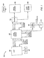
- reference numeral 50 generally indicates an asset tracking system.
- the system 50 includes a group of antennas 52 installed in association with a portal or doorway.
- the portal antennas 52 are arranged to receive signals generated by a marker 54.
- a marker signal reader device 56 is connected to the portal antennas 52.
- the reader 56 controls operation of the portal antennas 52 and reads data present in the signal generated by the marker 54.
- the reader 56 also receives data from, and may provide control signals for controlling, other devices installed at the portal.
- These other devices are represented by a block 58, and may include an electromechanical door lock, a biometric reading unit, status indicator lights, or the like.
- the reader 56 is also connected to exchange data with a local control module 60.
- Data provided from the reader 56 to the local control module 60 includes individual or asset identification data transmitted from the marker 54 and received by the reader 56 through the portal antennas 52.
- Data provided from the control module 60 to the reader 56 may include appropriate commands, including commands permitting passage of an individual or asset through the portal.
- the control module 60 is connected to exchange data with several other readers like the reader 56 shown in FIG. 1.
- the control module 60 also controls a video camera 62 and a VCR 64.
- the local control module 60 is connected for data communication with a host computer 66.
- the host computer 66 is interfaced with a printer 67 which may be used to print reports derived from a database stored in the host computer 66.
- the host 66 is connected to other local control modules in additional to the local control module 60 shown in the FIG. 1.
- the number of other local control modules may be large, amounting to several hundred in some cases.
- Each of the local control modules may be connected to gather data from a respective group of readers comprising several readers. Accordingly, the total number of readers in the system may be quite large, amounting in some embodiments to more than a thousand readers, each connected to receive signals from a respective antenna installation or installations at one or more portals.
- Data indicating passage of individuals or assets through the various portals is uploaded via the local control modules to computer 66 to provide a comprehensive and virtually real-time database record of movement of individuals and assets bearing the transponders used in the system.
- the transponders used as the markers 54 are of the types provided by Texas Instruments in connection with its "TIRIS" automatic identification system. This type of transponder is not provided with a battery or any other type of internal power source. Rather, an interrogation signal is transmitted from the portal antennas 52 to stimulate the transponder to transmit its unique identification signal. The interrogation signal is also a radiated power signal which charges up a power storage capacitor within the transponder. The stored power is then used by the transponder to transmit the transponder's identification signal.
- FIG. 2 A typical interrogation/response cycle for the "TIRIS" transponder is shown in FIG. 2.
- the horizonal axis in FIG. 2 represents elapsed time, while the vertical axis represents the state of charging of the transponder's storage capacitor.
- the interrogation signal/power burst is transmitted from the antenna 52, and the transponder's power storage capacitor is accordingly charged up during this time period. Then, during the period from time T2 to time T3, the stored power is used by the transponder to transmit a modulated identification signal using a frequency shift keying system in which one of the transmitted frequencies is the same as the frequency of the interrogation/power signal.
- the period between time T3 and time T4 is reserved for signal processing or the like at reader 56, and then the time T4 marks the beginning of another interrogation/response cycle.
- a problem encountered with this type of transponder system is the need to synchronize operations of readers which control neighboring antenna installations.
- the interrogation signal transmitted from one antenna coincides in time with the marker identification signal transmitted by a marker that has just been interrogated by a neighboring antenna, then the marker identification signal may be interfered with or "jammed" by the coincident neighboring interrogation signal.
- a reader or another device, is designated to be a "master" device which transmits timing or synchronizing signals to all of the readers in the system, or to all readers in a group of neighboring readers.
- the readers acknowledge the synchronization signal and transmit interrogation signals only at a timing determined in accordance with the synchronizing signals transmitted by the master unit.
- a disadvantage of this technique is that a large part or all of the asset control system can be disabled if the master unit happens to go out of service.
- Another known technique does not use a master unit which generates synchronizing signals. Instead, each reader is required to "listen" for potentially interfering signals and to initiate the interrogation/response cycle only at times when no interfering signals are detected.
- a disadvantage of this technique is that the timing at which each reader transmits interrogation signals is not deterministic and can be indefinitely delayed, resulting in a reduced number of interrogation cycles per unit time and deterioration of the system's performance in terms of detecting and tracking transponders.
- US 4,596,012 discloses an apparatus and a method which permits a plurality of master stations to be attached to a communications channel and to provide an arbitrating mechanism within each master by which one master station is designated as in control of the communications channel.
- the method overcomes the single point failure of the true master slave station by providing redundant masters.
- each station in the network is polled by a grand transmission at a constant interval of time irrespective of which master is in control of the bus to assure efficient utilization of the bus.
- EP 0 642 096 A2 discloses an updatable, interrogation system provided for simultaneously interrogating a plurality of portable data cards.
- a method of synchronizing a plurality of electronic devices including a master unit and a plurality of other units, with the method including the steps of transmitting a synchronizing signal at predetermined intervals from the master unit to at least one of the other units, and, in each of at least two of the other units, detecting whether a synchronizing signal is received by each of the at least two other units within a respective predetermined period of time and changing a mode of operation of the respective other unit if a synchronizing signal is not received by the respective other unit within the respective predetermined period of time.
- the mode of operation of the respective other unit may be changed from a first mode of operation in which the respective other unit transmits a synchronizing signal only in response to receiving a synchronizing signal to a second mode of operation in which the respective other unit transmits a synchronizing signal at predetermined intervals without receiving a synchronizing signal.
- the mode of operation of the respective other unit may be changed from a first mode of operation in which the respective other unit does not transmit any synchronizing signal to a second mode of operation in which the respective other unit transmits a synchronizing signal at predetermined intervals.
- a synchronized network of electronic devices including a plurality of electronic devices and means for interconnecting the devices for transmission of synchronizing signals among the devices, with the plurality of electronic devices including (a) a master unit for transmitting a synchronizing signal at predetermined intervals to at least one other of the electronic devices and (b) at least two back-up units each for detecting whether a synchronizing signal is received by the back-up unit within a respective predetermined period of time and for transmitting a synchronizing signal at predetermined intervals if a synchronizing signal is not received by the respective back-up unit within the respective predetermined period of time.
- the means for interconnecting may include means for interconnecting the devices in daisy-chain fashion, with each device other than the master unit transmitting a synchronizing signal to a next one of the devices in response to receiving a synchronizing signal from a previous one of the devices.
- Each of the devices may include a first port for receiving synchronizing signals, a second port for transmitting synchronizing signals, and relay means for selectively providing a short-circuit connection between the first and second ports.
- the means for interconnecting may include a bus line for connecting all of the devices in common, with the respective predetermined period of time for each back-up unit being different in duration from the respective predetermined period of time for each of the other back-up units.
- each of the devices includes means for transmitting an electronic article surveillance interrogation signal, and each device other than the master unit transmits the interrogation signal in response to receiving a synchronizing signal.
- a synchronized network of electronic devices including a master device which includes means for generating synchronizing signals at regular intervals and an output terminal for outputting the synchronizing signals, a second device including an input terminal connected to the output terminal of the master device, means for generating a synchronizing signal in response to receipt of the synchronizing signal at the input terminal, and an output terminal for outputting the synchronizing signal generated by the means for generating of the second device, and a third device which includes an input terminal connected to an output terminal of the second device, means for generating a synchronizing signal in response to receipt of a synchronizing signal at the input terminal of the third device and an output terminal for outputting the synchronizing signal generated by the means for generating of the third device.
- the second device includes means for determining whether a synchronizing signal is received at the input terminal of the second device during a predetermined period of time and for generating synchronizing signals at regular intervals if it is determined that no synchronizing signal is received at the input terminal of the second device during the predetermined period of time.
- the synchronized network of electronic devices may further include a fourth device having an input terminal connected to an output terminal of the third device, with the third device including means for determining whether a synchronizing signal was received at the input terminal of the third device during a respective predetermined period of time and for generating synchronizing signals at regular intervals if it is determined that no synchronizing signal is received at the input terminal of the third device during the respective predetermined period of time.
- the second, third, and fourth devices may all be substantially identical to each other and may be electronic article surveillance readers which include means for generating a signal for interrogating an electronic article surveillance marker in response to receipt of a synchronizing signal at the input terminal of the respective device.
- the master device may also be an electronic article surveillance reader which includes means for generating signals for interrogating an electronic article surveillance marker at regular intervals in synchronism with the synchronizing signals generated by the master device.
- a device for reading an electronic article surveillance marker including receive means for receiving a synchronizing signal, means for generating, in response to receipt of the synchronizing signal by the receive means, an interrogation signal for interrogating the marker, control means for determining whether a synchronizing signal is received by the receive means during a predetermined period of time, and sync means, responsive to the control means, for generating periodic synchronizing signals at regular intervals, and for generating interrogation signals at regular intervals in synchronism with the periodic synchronizing signals generated at regular intervals, if it is determined by the control means that no synchronizing signal is received by the receive means during the predetermined period of time.
- a device for reading an electronic article surveillance marker including receive means for receiving synchronization signals, interrogation means for generating interrogation signals for interrogating the marker, and sync means for generating synchronization signals, with the device being selectively operated in a first mode of operation in which the interrogation means and the sync means are responsive to the receive means for respectively generating an interrogation signal and a synchronization signal upon receipt of the synchronizing signal by the receive means and a second mode of operation in which the interrogation means and the sync means respectively generate interrogation signals and synchronization signals at regular intervals in synchronism with each other during periods in which the receive means receives no synchronization signals, the device further including control means, operatively associated with the receive means, the interrogation means and the sync means for switching the device between the first and second modes of operation.
- a synchronized network of electronic devices including a synchronizing signal bus connection; a master device including circuitry for generating synchronizing signals at regular intervals, a first output terminal connected to the synchronizing signal bus connection for transmitting the synchronizing signals onto the bus connection, and a second output terminal for outputting the synchronizing signals; a back-up device including circuitry for selectively generating synchronizing signals at regular intervals, an output terminal connected to the synchronizing signal bus connection for transmitting onto the bus connection the synchronizing signals selectively generated in the back-up device, and an input terminal connected to the second output terminal of the master device for receiving the synchronizing signals outputted from the second output terminal; and a plurality of slave devices connected to the synchronizing signal bus connection for receiving the synchronizing signals transmitted from the first output terminal of the master device and for operating in synchronism with the synchronizing signals received by the slave devices.
- the back-up device may also include a second output terminal for outputting synchronizing signals generated in the back-up device and the network may also include an additional device which includes circuitry for selectively generating synchronizing signals at regular intervals, an output terminal connected to the synchronizing signal bus connection for transmitting onto the bus connection the synchronizing signals selectively generated in the additional device, and an input terminal connected to the second output terminal of the back-up device for receiving the synchronizing signals generated in the back-up device.
- each of the slave devices may be an electronic article surveillance reader which includes circuitry for generating a signal for interrogating an electronic article surveillance marker in response to receipt of a synchronizing signal
- each of the master device and the back-up device may be an electronic article surveillance reader.
- the back-up device may include circuitry for determining whether a synchronizing signal is received at the input terminal of the back-up device during a predetermined period of time, with the back-up device being arranged to enter into a mode of operation in which the back-up device generates synchronizing signals at regular intervals and transmits those signals onto the synchronizing signal bus connection, if it is determined that no synchronizing signal is received at the input terminal of the back-up device during the predetermined period of time.
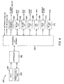
- the major components of the reader 56 are a controller board 142, a radio frequency module 144, a transmit/receive multiplex board 146, an L-expansion board 148 and a dynamic auto-tuning module 150.
- the controller board 142 exchanges data with the local control module 60 (FIG. 1) to which the reader 56 is connected, and also may provide command signals for other portal devices 58 (FIG. 1) and/or may exchange data with the other portal devices.
- the reader controller board 142 also controls the RF module 144 and the transmit/receipt multiplexer board 146 for the purpose of controlling the transmission of interrogation signals from, or receipt of transponder signals through, portal antenna 52.
- the L-expansion board 148 associated with RF module 144 is provided to accommodate the reader 56 to variations in length of the cable connecting the reader 56 to the antenna 52.
- the dynamic auto tuning module 150 is also provided in association with RF module 144, for the purpose of maintaining the portal antennas in a correct tuning condition.
- the controller board 142 includes a controller 152, which may be constituted by a conventional control circuit such as the model 80C320 microcontroller available from Dallas Semiconductor Corp., Dallas, Texas.
- An input device 154 is connected to the controller 152 for the purpose of providing various control and calibration setting signals.
- Also associated with the controller 152 is conventional power conditioning and electromagnetic interference suppression circuitry 156.
- An interface decoder 158 is provided to route data and control signals between the microcontroller 152 and various input/output and peripheral devices, including a Weigand encoding unit 160, an RS232 interface 162, an RS485 interface 164, a relay driver and interface 166, an LED driver and interface 168 and a piezo driver and interface 170.
- a Weigand encoding unit 160 an RS232 interface 162
- an RS485 interface 164 a relay driver and interface 166
- an LED driver and interface 168 and a piezo driver and interface 170.
- the RS422 interface 172 is Also connected to the controller 152 by way of the peripheral decoder 158 is an RS422 interface 172.
- the RS422 interface 172 is provided for receipt and/or transmission of synchronizing signals used to synchronize operation of the reader 56 and other readers in the asset tracking system 50, in accordance with techniques to be described below.
- a daisy-chain arrangement for interconnecting some or all of the readers included in the asset tracking system is shown in FIG. 5. If fewer than all of the readers are interconnected together, it is to be understood that, at least, each group of neighboring readers is interconnected.
- a reader 56-1 is at the head of the chain of readers, with other readers 56 provided downstream from the reader 56-1.
- a signal path connection 201 is provided from the reader 56-1 to the next reader in the chain, and from each reader downstream from the reader 56-1 to a following reader in the chain.
- the signal connection 201 may be provided in the form of an 18 gauge twisted-pair wire, for example.
- the sync signal connection is made through the respective reader's RS422 interface and an associated port or ports.
- Respective antennas 52 controlled by each reader 56 are also shown in FIG. 5.
- the number of readers 52 daisy-chained together may, of course, exceed the four readers explicitly shown in FIG. 5.
- FIG. 7 illustrates, in a somewhat schematic and simplified form, an embodiment of a reader 56 adapted for use in the daisy-chain arrangement shown in FIG. 5.
- the reader 56 as shown in FIG. 7 includes a control function 202, a sync pulse detection function 204, a sync pulse generating function 206, a timing function 208 and an interrogation signal generating function 210.
- the functions 202, 204, 206 and 208 may be constituted, at least in part, by the controller 152 (FIG. 4).
- Programming signals are provided for the control function 202 by means of the previously mentioned input device 154 (FIG. 4), which is also shown in FIG. 7.
- a power supply 212 (which may be constituted, at least in part, by the power conditioning and EMI circuit 156) is also provided in the reader 56 as a source of power for the components making up the reader 56.
- a power sense function 214 is associated with the power supply 212 for the purpose of detecting failure of the power supply 212.
- the power sense function 214 may be constituted, in part, by the controller 152.
- the reader 56 also has an input port 216 for receiving synchronizing signals and an output port 218 for transmitting synchronizing signals generated in the reader 56.
- a relay circuit 220 is connected between the input port 216 and the output port 218.
- the relay circuit 220 is normally maintained in the position shown in FIG. 7 so that synchronizing signals received at the input port 216 are provided for detection by the pulse detecting function 204.
- the relay circuit 220 is switched to a position in which the input port 216 is directly connected to the output port 218. In this way, a failure of the power supply for the reader 56 will not "break the chain" of the sync signal network depicted in FIG. 5.
- the ports 216 and 218, relay circuit 220 and a portion of the pulse detection and generation functions, may be constituted by the RS422 interface 172 shown in FIG. 4.
- step 252 After power is supplied to the reader (step 250), an initialization routine is carried out (step 252).
- step 258 a predetermined time-out interval is initiated.
- the time-out interval may be twice as long as the duration of interrogation signal cycle shown in FIG. 2 (that is, twice as long as the time interval from time T1 to time T4.)
- step 260 at which it is determined whether a synchronizing signal is received at the input port 216 of the reader prior to expiration of the time-out period.
- step 262 follows step 260.
- the reader generates a synchronizing signal in response to the synchronizing signal received at the input port 216 and transmits from the output port 218 the synchronizing signal generated by the reader.
- the reader generates an interrogation signal. Accordingly, it will be recognized that the timing at which interrogation signals are generated by the reader is controlled by the timing at which synchronizing signals are received at the input port 216, when the reader is functioning as a slave unit.
- step 262 the procedure of FIG. 9 loops back to step 258, at which the time-out period is again initiated. Assuming that synchronizing signals are received at the desired regular intervals, the procedure of FIG. 9 will simply loop through steps 258, 260 and 262 repeatedly, generating interrogation signals and synchronizing signals for re-transmission down the daisy-chain at regular intervals in synchronism with received synchronizing signals.
- the reader 56 is arranged so that detection of the received synchronizing signal and generation and re-transmission of a synchronizing signal in response to the received synchronizing signal are performed quite rapidly and signal propagation delay down the daisy-chain is minimal in comparison with the duration of the desired interrogation signal cycle (FIG. 2).
- step 264 follows step 260, causing the reader in question to act as a master unit. Specifically, in step 264, the reader generates synchronizing signals, and also interrogation signals in synchronism with the synchronizing signals, based on the reader's internal timing function and in accordance with the timing cycle illustrated in FIG. 2. However, in addition, the reader continues to "listen"0 for synchronizing signals received at the input port 216 (step 266).
- step 268 follows step 266.
- the reader responds to the received synchronizing signal by generating internally a synchronizing signal to be transmitted via the output port 218, and the reader 56 also generates an interrogation signal.
- the reader stops generating synchronizing signals and interrogation signals based on its internal timing (step 270), and the procedure loops back to step 258, thereby returning the reader to the loop consisting of steps 258, 260 and 262, in which the reader functions as a slave unit.
- each of the readers shown in FIG. 5 is like the reader shown in FIG. 7 and operates according to the flow-diagram of FIG. 9, with the reader 56-1 at the head of the daisy-chain network acting as a master unit and the other readers functioning as slave units.
- Each reader other than the master unit receives a sync signal, and, in response to receiving the sync signal, generates a sync signal to be propagated down the daisy-chain.
- each reader other than the master responds to receiving a sync signal by generating an interrogation signal.
- the sync signals propagating through the daisy-chain cause all of the daisy-chained readers to operate with synchronized interrogation signal cycles, thereby preventing each antenna from interfering with the transponder signal receiving portion of the interrogation signal cycle of neighboring antennas.
- every reader included in the asset tracking system be connected to the same daisy-chain.
- two or more daisy-chains may be provided, configured so that any pair of antennas that are close enough to each other to interfere with each other are connected via the same daisy-chain.
- the next unit in the chain will detect the absence of synchronizing signals at its input port, and will take over as a back-up master unit, in accordance with step 264 of FIG. 9. If the reader acting as the back-up master unit fails, then the next reader in the chain similarly will take over the function of master unit. Also, as previously noted, if a slave unit fails, the slave unit is arranged to provide a direct connection between its input and output ports so that only the failed slave unit, but not the balance of the chain, is put out of service. It will be recognized that the number of back-up units that can be provided according to the arrangement of FIG.
- contention will quickly be resolved in favor of the unit immediately downstream from the master within one or two interrogation signal cycles.
- the resolution of the contention results from the operation of steps 266, 268 and 270 in the units downstream from the slave unit that is closest to the master.
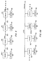
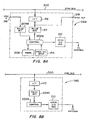
- the daisy-chain arrangement shown in FIG. 5 is a preferred embodiment of the invention because of the relatively low signal current levels that are needed for the transmitted and retransmitted sync signals, and also because of the automatic prioritization of back-up units mentioned in the preceding paragraph. Nevertheless, it is also contemplated to provide multiple back-ups for a master unit in a common-bus-configured arrangement, as illustrated, for example, in FIG. 6A. In particular, the arrangement of FIG.
- 6A includes a common sync bus 300 to which are attached a number of readers 56M (including a unit designated 56M-1) which are capable of acting as master units, and a further group of readers 56S, which function as slave units that generate interrogation signals in response to sync signals transmitted via the sync bus 300 to the slave units from the one of the readers 56M which is acting as master.
- readers 56M including a unit designated 56M-1 which are capable of acting as master units
- readers 56S which function as slave units that generate interrogation signals in response to sync signals transmitted via the sync bus 300 to the slave units from the one of the readers 56M which is acting as master.
- each slave unit 56S is connected to the sync bus 300 so as to receive sync signals present on the sync bus.
- each reader 56M is connected to the sync bus 300 so as to be capable of applying a sync signal to the sync bus, but only the unit acting as the master unit actually applies sync signals to the sync bus.
- the readers 56M are connected in a daisy-chain arrangement by connections 301, with reader 56M-1 at the head of the chain and followed by two back-up units. It is contemplated that fewer or more than two back-up units may be daisy-chained to the reader 56M-1. It is also contemplated to connect to the sync bus 300 more or fewer than the three slave units 56S explicitly shown in FIG. 6A and to connect slave units to any point on the sync bus 300. The master and back-up units may also be connected at any point on the sync bus, although daisy-chaining of the master and back-up units can be more easily accomplished if the master and back-up units are located near to each other.
- a control function 202M is connected to receive sync signals via an input port 216 and a sync signal detection function 204M.
- each reader 56M has its control function 202M connected to the sync bus 300 via a sync signal generating circuit 206M and its RS422 interface 172, so that the reader can apply sync signals to the bus 300.
- the control function 202M is also able to transmit sync signals from an output port 218 through the sync signal generating function 206M.
- Also associated with the control function 202M are an internal timing function 208, an interrogation signal generating function 210 and a programming signal input device 154, all of which may be like the corresponding portions of the reader shown in FIG. 7.
- each reader 56M may also include a mechanism (like switch 220 and power sense function 214 of FIG. 7) for selectively providing a direct connection between its input and output ports.
- FIG. 10A Operation of the daisy-chained readers 56M is illustrated in FIG. 10A and is similar to that of readers 56 (FIGS. 7 and 9).
- the operating procedure of FIG. 10A because of its similarity to that of FIG. 9, need not be explained in detail except to note the inclusion in FIG. 10A of a step 265 between steps 264 and 266.
- the step 265 indicates that when a reader 56M is functioning as a master unit, it applies sync signals to the sync bus 300 while simultaneously transmitting sync signals via its output port 218 to the first back-up unit. (By contrast, in the daisy-chain arrangement, the lead unit only transmits sync signals from its output port.) Otherwise, the procedure of FIG. 10A is like that of FIG.
- the reader When operating as a master unit, the reader generates interrogation and sync signals based on internal timing, and transmits the sync signals both to all of the slave units, via the sync bus, and to the back-up unit immediately downstream via output port 218.
- the reader When operating as a back-up unit, the reader generates interrogation and sync signals only in response to sync signals received via its input port, and, in this mode, the reader only retransmits sync signals via its output port. That is, back-up units do not retransmit sync signals over the sync bus, unless operating as a master unit.
- the mode in which a reader 56M operates is determined by the presence or absence of sync signals at its input port. If sync signals are received at regular intervals shorter than the time-out period, then the reader 56M stays in back-up mode. For the unit 56M-1 at the head of the chain, of course no sync signals are provided, so that unit 56M-1 automatically enters the master mode. The other units will remain in the back-up mode unless the master unit fails. Contention is resolved on the basis of position in the daisy-chain., as discussed in connection with FIG. 9.
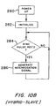
- the slave units 56S are illustrated in simplified functional form in FIG. 8B.
- Each unit 56S includes a control function 202S, connected to receive sync signals from the sync bus 300 via an interface 172 and a sync detection function 204S.
- An interrogation signal generating function 210 generates interrogation signals under the control of control function 202S.
- the slave reader 56S operates so that it generates interrogation signals only in response to synchronizing signals provided on the sync bus 300.
- the slave reader is powered up and initialized (steps 280 and 282 in FIG. 10B) and then waits to receive a synchronizing signal (step 284).
- the slave reader Upon receiving a synchronizing signal, the slave reader generates an interrogation signal (step 286) and then again waits to receive a synchronizing signal. All of the slave readers operate in the same manner, and, accordingly, the operation of all readers 56S is synchronized through the sync bus, under control of the reader 56M which is acting as the master unit.
- the synchronizing network arrangement of FIG. 6A may be considered a hybrid of a bus and a daisy-chain arrangement, since the slave units are controlled through the sync bus 300, and priority among the master units and back-up units is determined through a daisy-chain connection. It will be noted that the master and back-up units need not be readers, i.e., need not include interrogation signal generation and marker signal reading functions.
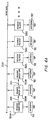
- FIG. 6B shows a sync bus 300 having attached thereto a plurality of readers 56', all of which are capable of acting as a master unit.
- the number of readers attached to the bus 300 may, of course, be much larger than the four units explicitly shown in FIG. 6B.
- the reader 56'(M) designated as the master unit for controlling the synchronization of the other units may be located at essentially any point along the sync bus 300.
- the readers 56' differ in some respects from the readers used in the arrangements that were previously described.
- the reader 56' is connected to the bus 300 through an interface circuit (constituted by RS422 interface 172 shown in FIG. 4), and includes a control function 202', a sync signal detection function 204' and a sync signal generation function 206'.
- the functions 202', 204' and 206' are generally similar, respectively, to the functions 202, 204 and 206 of the reader 56 described in connection with FIG. 7.
- the reader 56' of FIG. 8C also includes a programming signal input device 154, an internal timing function 208 and an interrogation signal generating function 210, all of which may be essentially the same as the corresponding portions of reader 56.
- an initialization routine is carried out (step 352). It is then determined, at step 354, whether the reader 56' has been designated to act as a master unit which controls the timing of all of the readers connected to the sync bus. This determination may be made, for example, by receiving an appropriate programming signal through the input device 154, or by determining whether a signal designating the reader 56' as a master unit has been stored in the reader 56' after having previously been input into the reader via the input device 154.
- step 356 follows, at which the reader 56' generates synchronizing signals at regular intervals based upon timing provided by the timing function 208 which is included in the reader 56'.
- the reader 56' also generates interrogation signals, through interrogation signal generating function 210, in synchronism with the synchronizing signals generated within the reader 56'.
- both the synchronizing signals and the interrogation signals are generated in accordance with the timing cycle illustrated in FIG. 2.
- the common bus arrangement of FIG. 6B does not permit establishment of priority among back-up units based on proximity to the head of a daisy chain, as provided in the arrangements of FIG. 5 and 6A. Another method of establishing priority among potential back-up master units is therefore required. According to a preferred implementation of the bus-based arrangement of FIG. 6B, priority among the back-up units is established by causing the back-up units to have different respective time-out periods. Specifically, in the procedure of FIG. 10C, if the particular reader is not designated to act as a master unit, then step 357 follows up 354.
- the reader sets the duration of its time-out period, so that it has a different time-out period (either longer or shorter) then the time-out period of any other reader. This may be done, for example, by providing unique addresses for each back-up unit (such as 2, 3, 4, and so forth) and then calculating the time-out period for each reader on the basis of its address.
- the reader at address 2 could have a time-out period equal in duration to twice the interrogation signal cycle; the reader at address 3 could have a time-out period equal in duration to three times the interrogation cycle, and so forth.
- step 358 at which the time-out period is commenced.
- the reader then waits to receive a sync signal via the sync bus 300, and if a sync signal is detected before the end of the reader's time-out period, then the reader generates an interrogation signal in response to receiving the sync signal and the routine then loops back to step 358. So long as the master unit is operating properly, sync signals will be provided on the sync bus 300 by the master unit at regular intervals shorter than the pre-determined time-out periods of each of the other readers, and each reader will continue to operate in the slave mode made up of steps 358 and 360. As a result, all of the readers will generate interrogation signals in synchronism with the sync signal produced by the master unit.
- step 364 the reader unit which timed out takes over as master unit and generates sync signals based on its internal timing. These sync signals are transmitted through the sync bus 300 to the other readers so that all of the readers, including the reader acting as back-up master unit, generate interrogation cycles in synchronism with sync signals generated by the back-up unit. Meanwhile, the back-up unit "listens" on the bus for sync pulse contention, which could occur if the master unit goes back into operation or if another unit has also attempted to take over as a back-up master unit.
- step 366 the reader stops generating sync signals based on its internal timing and returns to the loop of steps 358 and 360. Because of the variation in the time-out periods among the readers, any contention can be promptly resolved (i.e., resolved within a few interrogation cycles).
- sync bus 300 of FIGS. 6A and 6B is preferably in the form of a suitable wire or cable connection, but can also be provided in the form of a shared wireless communication channel. It is also contemplated that a number of slave units 56S as shown in FIG. 8B, could be connected to the sync bus 300 in the "pure" bus arrangement of FIG. 6B.
- the synchronization techniques disclosed herein have been described in connection with a network of asset surveillance and tracking system reader devices, the invention is considered to be applicable to other types of electronic devices.
- the disclosed technique can be used in a disk drive unit made up of a number of disk drives that are to be synchronized in terms of rotational phase. It is also contemplated that readers in an asset tracking system could be synchronized through the local control modules 60 (FIG. 1) that are part of the system.
- the local control modules could be synchronized according to the daisy-chain and/or bus techniques disclosed above, and each local control module would then send synchronizing signals to its respective reader units in synchronism with sync signals provided through the daisy-chain or bus synchronizing network used to interconnect the local control modules.
Landscapes
- Engineering & Computer Science (AREA)
- Computer Networks & Wireless Communication (AREA)
- Physics & Mathematics (AREA)
- General Physics & Mathematics (AREA)
- Small-Scale Networks (AREA)
- Synchronisation In Digital Transmission Systems (AREA)
Claims (29)
- Procédé de sécurisation de la synchronisation d'une pluralité de dispositifs électroniques (56) comprenant une unité dans le mode d'unité maître et une pluralité d'autres unités, comprenant les étapes consistant à :transmettre un signal de synchronisation à des intervalles prédéterminés à partir de l'unité maître (56) à au moins deux des autres unités (56), qui sont dans le mode d'unités asservies, le but de chacun des dits signaux de synchronisation étant d'initier un fonctionnement d'un dispositif ayant reçu le signal synchronisation respectifcaractérisé par
le fait qu'il comprend les étapes consistant à
détecter dans les au moins deux autres unités (56) si le signal de synchronisation est reçu par l'autre unité respective (56) dans un laps de temps ou intervalle temporel prédéterminé et
changer un mode de fonctionnement de l'autre unité respective d'un mode d'unité asservie à un mode d'unité maître si le signal de synchronisation n'est pas reçu par l'autre unité respective (56) dans le laps de temps ou intervalle temporel prédéterminé respectif. - Procédé selon la revendication 1, dans lequel, si un signal de synchronisation n'est pas reçu par l'autre unité respective (56) dans le laps de temps respectif prédéterminé, le mode de fonctionnement de l'autre unité respective (56) passe d'un premier mode de fonctionnement dans lequel l'autre unité respective ne transmet un signal de synchronisation qu'en réponse à la réception d'un signal de synchronisation, à un deuxième mode de fonctionnement dans lequel l'autre unité respective (56) transmet un signal de synchronisation à des intervalles prédéterminés sans recevoir de signal de synchronisation.
- Procédé selon la revendication 1, dans lequel, si un signal de synchronisation n'est pas reçu par l'autre unité respective (56) dans le laps de temps respectif prédéterminé, le mode de fonctionnement de l'autre unité respective (56 M) passe d'un premier mode de fonctionnement dans lequel l'autre unité respective ne transmet aucun signal de synchronisation, à un deuxième mode de fonctionnement dans lequel l'autre unité respective (56 M) transmet un signal de synchronisation à des intervalles prédéterminés.
- Réseau synchronisé de dispositifs électroniques, comprenant une pluralité de dispositifs électroniques (56) et un moyen (201, 300) permettant d'interconnecter les dispositifs (56) pour la transmission de signaux de synchronisation parmi les dispositifs (56), le but de chacun des dits signaux de synchronisation étant d'initier un fonctionnement d'un dispositif qui reçoit le signal synchronisation,
comprenant en outre(a) une unité maître (56 M) destinée à transmettre un signal de synchronisation à des intervalles prédéterminés à au moins deux autres des dits dispositifs électroniques (56), et ledit réseau synchronisé étant caractérisé par(b) au moins deux unités de secours ou de réserve (56), chacune étant destinée à détecter si un signal de synchronisation est reçu par l'autre unité de secours ou de réserve respective (56) dans un laps de temps ou intervalle prédéterminé et à transmettre un signal de synchronisation à des intervalles prédéterminés si un signal de synchronisation n'est pas reçu par l'autre unité de secours respective dans le laps de temps ou intervalle respectif prédéterminé. - Réseau synchronisé de dispositifs électroniques (56) selon la revendication 4, dans lequel l'unité maître (56 M) transmet le signal de synchronisation en réponse à un signal de cadencement généré dans l'unité maître (56 M).
- Réseau synchronisé de dispositifs électroniques selon la revendication 5, dans lequel ledit moyen d'interconnexion est un moyen d'interconnexion des dispositifs (56) selon un mode en chaîne ou en guirlande, et dans lequel chaque dispositif (56) autre que l'unité maître (56 M) transmet un signal de synchronisation à un dispositif suivant des dits dispositifs en réponse à la réception d'un signal de synchronisation d'un dispositif précédent des dits dispositifs (56).
- Réseau synchronisé de dispositifs électroniques selon la revendication 6, dans lequel chacun des dits dispositifs (56) comprend un premier port (216) pour la réception de signaux de synchronisation, un deuxième port (218) pour la transmission de signaux de synchronisation et un moyen de relais pour réaliser sélectivement une connexion en court-circuit entre lesdits premier et deuxième ports.
- Réseau synchronisé de dispositifs électroniques selon la revendication 7, dans lequel chacun desdits dispositifs (56) comprend un moyen (210) destiné à la transmission d'un signal d'interrogation de surveillance électronique d'article, et chacun des dits dispositifs (56) autres que l'unité maître (56 M) transmet ledit signal d'interrogation en réponse à la réception d'un signal de synchronisation.
- Réseau synchronisé de dispositifs électroniques selon la revendication 4, dans lequel ledit moyen d'interconnexion comprend un bus (300) pour la connexion de tous les dispositifs (56 M, 56) entre eux, et le laps de temps prédéterminé respectif de chacune des unités de secours est différent du laps de temps prédéterminé respectif pour chacune des autres unités de secours (56).
- Réseau synchronisé de dispositifs électroniques selon la revendication 9, dans lequel chacun desdits dispositifs (56) comprend un moyen (52) destiné à la transmission d'un signal d'interrogation de surveillance électronique d'article, et chacun des dits dispositifs autres que l'unité maître (56 M) transmet ledit signal d'interrogation en réponse à la réception d'un signal de synchronisation.
- Réseau synchronisé de dispositifs électroniques selon l'une des revendications 4 à 10, précédentes,
caractérisé par
le fait qu'il comprend:ledit dispositif maître (56 M) intégrant un moyen de génération de signaux de synchronisation à intervalles réguliers et une borne de sortie pour émettre les signaux de synchronisation ;ledit deuxième dispositif (56) comprenant une borne d'entrée (216) connectée à la borne de sortie (218) de l'unité maître (56 M), un moyen de génération d'un signal de synchronisation en réponse à la réception d'un signal de synchronisation sur la borne d'entrée (216), et une borne de sortie (218) pour émettre le signal de synchronisation généré par le moyen de génération de signal du deuxième dispositif ; etun troisième dispositif comprenant une borne d'entrée (216) connectée à la borne de sortie de la deuxième unité, un moyen de génération d'un signal de synchronisation en réponse à la réception d'un signal de synchronisation sur la borne d'entrée du troisième dispositif, et une borne de sortie destinée à émettre le signal de synchronisation généré par le moyen de génération de signal du troisième dispositif ;ledit deuxième dispositif (56) comprenant en outre un moyen destiné à déterminer si un signal de synchronisation est reçu sur la borne d'entrée du deuxième dispositif pendant un laps de temps prédéterminé et à générer des signaux de synchronisation à intervalles réguliers s'il est déterminé qu'aucun signal de synchronisation n'est reçu sur la borne d'entrée du deuxième dispositif pendant le laps de temps prédéterminé. - Réseau synchronisé de dispositifs électroniques selon la revendication 11, comprenant en outre un quatrième dispositif (56) dont une borne d'entrée est connectée à la borne de sortie (218) du troisième dispositif (56), et dans lequel le troisième dispositif (56) comprend en outre un moyen destiné à déterminer si un signal de synchronisation est reçu sur la borne d'entrée (216) du troisième dispositif (56) pendant un laps de temps prédéterminé respectif et à générer des signaux de synchronisation à des intervalles réguliers s'il est déterminé qu'aucun signal de synchronisation n'est reçu sur la borne d'entrée (216) du troisième dispositif (56) pendant le laps de temps prédéterminé respectif.
- Réseau synchronisé de dispositifs électroniques selon la revendication 12, dans lequel le deuxième, le troisième et le quatrième dispositifs (56) sont sensiblement identiques.
- Réseau synchronisé de dispositifs électroniques selon la revendication 13, dans lequel chacun des deuxième, troisième et quatrième dispositifs (56) est un lecteur de surveillance électronique d'article comprenant un moyen (210) destiné à générer un signal pour interroger un marqueur de surveillance électronique d'article (54) en réponse à la réception d'un signal de synchronisation sur la borne d'entrée (216) du dispositif respectif (56).
- Réseau synchronisé de dispositifs électroniques selon la revendication 14, dans lequel le dispositif maître (56 M) est un lecteur de surveillance électronique d'article comprenant un moyen (210) destiné à générer des signaux pour interroger un marqueur de surveillance électronique d'article (54) à intervalles réguliers en synchronisme avec les signaux de synchronisation générés par le dispositif maître (56 M).
- Réseau synchronisé de dispositifs électroniques selon la revendication 15, dans lequel le deuxième dispositif (56) et le troisième dispositif (56) comprennent chacun un moyen respectif (210) destiné à générer des signaux pour interroger un marqueur de surveillance électronique d'article (54) à intervalles réguliers en synchronisme avec les signaux de synchronisation générés à intervalles réguliers par le dispositif respectif s'il est déterminé qu'aucun signal de synchronisation n'est reçu sur la borne d'entrée du dispositif respectif pendant le laps de temps prédéterminé respectif.
- Réseau synchronisé de dispositifs électroniques selon la revendication 16, dans lequel chacun des deuxième et troisième dispositifs (56) comprend un moyen de relais (220) destiné à réaliser sélectivement une connexion en court-circuit entre la borne d'entrée (216) et la borne de sortie (218) du dispositif respectif (56).
- Réseau synchronisé de dispositifs électroniques selon la revendication 13, comprenant en outre une pluralité d'autres dispositifs (56) connectés au quatrième dispositif (56) selon un mode en guirlande, chacun des autres dispositifs (56) étant sensiblement identique aux deuxième, troisième et quatrième dispositifs (56).
- Réseau synchronisé de dispositifs électroniques selon l'une des revendications 14 à 18 précédentes dans lequel le réseau comprend
un moyen de réception (216) d'un signal de synchronisation ;
un moyen (210) destiné à générer un signal d'interrogation du marqueur (54) en réponse à la réception du signal de synchronisation par le moyen de réception ;
un moyen de commande (202, 204) pour déterminer si un signal de synchronisation est reçu par le moyen de réception pendant un laps de temps prédéterminé ; et
un moyen de synchronisation (206), sensible au moyen de commande, destiné à générer des signaux de synchronisation périodiques à intervalles réguliers, et à générer des signaux d'interrogation à intervalles réguliers en synchronisme avec les signaux de synchronisation périodiques générés à intervalles réguliers, s'il est déterminé par le moyen de commande (202, 204) qu'aucun signal de synchronisation n'est reçu par le moyen de réception pendant un laps de temps prédéterminé. - Dispositif électronique selon la revendication 19, dans lequel ledit moyen de synchronisation (206) comprend un moyen, sensible au moyen de réception, destiné à retransmettre le signal de synchronisation reçu par le moyen de réception.
- Dispositif électronique selon la revendication 20, dans lequel ledit moyen de réception comprend un port d'entrée (216) et ledit moyen de synchronisation (206) comprend un port de sortie (218), le dispositif (56) comprenant en outre un moyen de relais (220) destiné à réaliser sélectivement une connexion en court-circuit entre ledit port d'entrée (216) et ledit port de sortie (218).
- Réseau synchronisé de dispositifs électroniques selon l'une des revendications 4 à 21 précédentes, comprenant :un moyen d'interrogation (210) destiné à générer des signaux d'interrogation du marqueur ; etun moyen de synchronisation (206) destiné à générer des signaux de synchronisation ;le dispositif étant sélectivement exploité dans un premier mode de fonctionnement dans lequel le moyen d'interrogation (210) et le moyen de synchronisation (206) sont chacun sensibles au moyen de réception (204) pour générer respectivement un signal d'interrogation et un signal de synchronisation à réception du signal de synchronisation par le moyen de réception (204) et un deuxième mode de fonctionnement dans lequel le moyen d'interrogation (210) et le moyen de synchronisation (206) génèrent respectivement des signaux d'interrogation et des signaux de synchronisation à intervalles réguliers de façon synchronisée entre eux pendant des périodes dans lesquelles le moyen de réception (204) ne reçoit pas de signaux de synchronisation, le dispositif comprenant en outre un moyen de commande (202), associé de façon opérationnelle au moyen de réception (204), au moyen d'interrogation (210) et au moyen de synchronisation (206), pour commuter le mode de fonctionnement du dispositif du premier mode au deuxième mode.
- Dispositif électronique selon la revendication 22, dans lequel le moyen de commutation comprend un moyen destiné à déterminer si un signal de synchronisation est reçu par le moyen de réception (204) pendant un laps de temps prédéterminé.
- Réseau synchronisé selon la revendication 22, comprenant en outre :une première borne de sortie (218) pour émettre ledit signal de synchronisation généré par le dispositif (56) dans le premier mode de fonctionnement ; etune deuxième borne de sortie, différente de ladite première borne de sortie et connectée à un bus de signaux de synchronisation (300), pour émettre les signaux de synchronisation générés par le dispositif dans le deuxième mode de fonctionnement.
- Réseau synchronisé selon l'une des revendications 4 à 24 précédentes, comprenant :une connexion de bus de signaux de synchronisation (300) ;un dispositif maître (56M) comprenant un moyen destiné à générer des signaux de synchronisation (206) à intervalles réguliers, une première borne de sortie connectée à ladite connexion de bus de signaux de synchronisation pour la transmission des signaux de synchronisation sur ladite connexion de bus (300), et une deuxième borne de sortie destinée à émettre les signaux de synchronisation ;un dispositif de secours ou de réserve (56) comprenant un moyen (206) destiné à générer sélectivement des signaux de synchronisation à intervalles réguliers, une borne de sortie connectée à ladite connexion de bus de signaux de synchronisation (300) pour transmettre sur ladite connexion de bus les signaux de synchronisation générés sélectivement dans le dispositif de secours, et une borne d'entrée connectée à ladite deuxième borne de sortie du dit dispositif maître (56 M) pour recevoir les signaux de synchronisation émis depuis ladite deuxième borne de sortie ; etune pluralité de dispositifs asservis ou esclaves (56) connectés à ladite connexion de bus de signaux de synchronisation (300) pour recevoir les signaux de synchronisation transmis depuis ladite première borne de sortie du dit dispositif maître (56 M) et pour fonctionner en synchronisme avec les signaux de synchronisation reçus par lesdits dispositifs asservis.
- Réseau synchronisé de dispositifs électroniques selon la revendication 25, dans lequel ledit dispositif de secours (56) comprend par ailleurs une deuxième borne de sortie pour émettre des signaux de synchronisation générés dans ledit dispositif de secours, et comprenant en outre :un dispositif supplémentaire comprenant un moyen destiné à générer sélectivement des signaux de synchronisation à intervalles réguliers, une borne de sortie connectée à ladite connexion de bus de signaux de synchronisation (300) pour transmettre sur ladite connexion de bus les signaux de synchronisation générés sélectivement dans le dispositif supplémentaire, et une borne d'entrée connectée à ladite deuxième borne de sortie du dit dispositif de secours (56) pour recevoir les signaux de synchronisation générés dans ledit dispositif de secours.
- Réseau synchronisé de dispositifs électroniques selon la revendication 25, dans lequel chacun des dispositifs asservis (56) est un lecteur de surveillance électronique d'article comprenant un moyen (210) destiné à générer un signal pour interroger un marqueur de surveillance électronique d'article (54) en réponse à la réception d'un signal de synchronisation par le dispositif asservi respectif (56).
- Réseau synchronisé de dispositifs électroniques selon la revendication 27, dans lequel les dispositifs maîtres (56 M) et le dispositif de secours ou de réserve (56) sont des lecteurs de surveillance électronique d'articles.
- Réseau synchronisé de dispositifs électroniques selon la revendication 25, dans lequel ledit dispositif de secours ou de réserve (56) comprend un moyen pour déterminer si un signal de synchronisation est reçu sur la borne d'entrée du dispositif de secours (56) pendant un laps de temps prédéterminé, ledit dispositif de secours (56) étant disposé pour passer dans un mode de fonctionnement dans lequel ledit dispositif de secours génère des signaux de synchronisation à intervalles réguliers et transmet lesdits signaux sur la connexion de bus de signaux de synchronisation (300), s'il est déterminé qu'aucun signal de synchronisation n'est reçu sur la borne d'entrée du dispositif de secours (56) pendant le laps de temps prédéterminé.
Applications Claiming Priority (3)
| Application Number | Priority Date | Filing Date | Title |
|---|---|---|---|
| US08/502,827 US5751220A (en) | 1995-07-14 | 1995-07-14 | Synchronized network of electronic devices including back-up master units |
| US502827 | 1995-07-14 | ||
| PCT/US1996/011504 WO1997004614A1 (fr) | 1995-07-14 | 1996-07-10 | Reseau electronique synchronise comprenant des unites pilotes d'assistance |
Publications (3)
| Publication Number | Publication Date |
|---|---|
| EP0878110A1 EP0878110A1 (fr) | 1998-11-18 |
| EP0878110A4 EP0878110A4 (fr) | 1999-05-19 |
| EP0878110B1 true EP0878110B1 (fr) | 2006-03-29 |
Family
ID=23999589
Family Applications (1)
| Application Number | Title | Priority Date | Filing Date |
|---|---|---|---|
| EP96924415A Expired - Lifetime EP0878110B1 (fr) | 1995-07-14 | 1996-07-10 | Reseau electronique synchronise comprenant des unites pilotes d'assistance |
Country Status (9)
| Country | Link |
|---|---|
| US (1) | US5751220A (fr) |
| EP (1) | EP0878110B1 (fr) |
| JP (1) | JP4671451B2 (fr) |
| AR (1) | AR002821A1 (fr) |
| AU (1) | AU705920B2 (fr) |
| BR (1) | BR9609720A (fr) |
| CA (1) | CA2226322C (fr) |
| DE (1) | DE69635994T2 (fr) |
| WO (1) | WO1997004614A1 (fr) |
Families Citing this family (90)
| Publication number | Priority date | Publication date | Assignee | Title |
|---|---|---|---|---|
| US6134234A (en) * | 1996-07-19 | 2000-10-17 | Nokia Telecommunications Oy | Master-slave synchronization |
| US6147967A (en) * | 1997-05-09 | 2000-11-14 | I/O Control Corporation | Fault isolation and recovery in a distributed control network |
| US6061600A (en) * | 1997-05-09 | 2000-05-09 | I/O Control Corporation | Backup control mechanism in a distributed control network |
| US5907486A (en) | 1997-05-09 | 1999-05-25 | I/O Control Corporation | Wiring method and apparatus for distributed control network |
| US6094416A (en) * | 1997-05-09 | 2000-07-25 | I/O Control Corporation | Multi-tier architecture for control network |
| US6128318A (en) * | 1998-01-23 | 2000-10-03 | Philips Electronics North America Corporation | Method for synchronizing a cycle master node to a cycle slave node using synchronization information from an external network or sub-network which is supplied to the cycle slave node |
| JP3609599B2 (ja) * | 1998-01-30 | 2005-01-12 | 富士通株式会社 | ノード代理システム、ノード監視システム、それらの方法、及び記録媒体 |
| JP2001077919A (ja) * | 1999-09-03 | 2001-03-23 | Fujitsu Ltd | 冗長構成監視制御システム並びにその監視制御装置及び被監視制御装置 |
| US7065779B1 (en) * | 1999-10-13 | 2006-06-20 | Cisco Technology, Inc. | Technique for synchronizing multiple access controllers at the head end of an access network |
| US6732202B1 (en) | 1999-11-17 | 2004-05-04 | I/O Controls Corporation | Network node with plug-in identification module |
| US8645582B2 (en) * | 1999-11-17 | 2014-02-04 | I/O Controls Corporation | Network node with plug-in identification module |
| US6611860B1 (en) | 1999-11-17 | 2003-08-26 | I/O Controls Corporation | Control network with matrix architecture |
| US6396170B1 (en) * | 2000-03-29 | 2002-05-28 | Powerware Corporation | Method and apparatus for coordinating uninterruptible power supply modules to provide scalable, redundant power |
| US6891805B2 (en) * | 2001-02-06 | 2005-05-10 | Telephonics Corporation | Communications system |
| US20020105916A1 (en) * | 2001-02-06 | 2002-08-08 | Bill Smith | Method and apparatus for allocating funtions in an electronics system |
| US6988203B2 (en) * | 2001-04-06 | 2006-01-17 | Honeywell International Inc. | System and method of extending communications with the wiegand protocol |
| US7349430B1 (en) | 2001-06-27 | 2008-03-25 | Cisco Technology, Inc. | Addressing scheme implemented in access networks |
| US7085287B1 (en) | 2001-06-27 | 2006-08-01 | Cisco Technology, Inc. | Map routing technique implemented in access networks |
| US7139923B1 (en) | 2001-06-27 | 2006-11-21 | Cisco Technology, Inc. | Technique for synchronizing network devices in an access data network |
| US7746215B1 (en) * | 2001-07-10 | 2010-06-29 | Fred Bishop | RF transactions using a wireless reader grid |
| WO2003010869A1 (fr) * | 2001-07-13 | 2003-02-06 | Shape Of Time, Inc. | Systeme et procede de gestion de reseau |
| US6848933B1 (en) * | 2001-11-13 | 2005-02-01 | Rockwell Automation Technologies, Inc. | System and methodology providing coordinated and modular conveyor zone control |
| US20030117281A1 (en) * | 2001-12-21 | 2003-06-26 | Timur Sriharto | Dynamic control containment unit |
| US7084769B2 (en) * | 2002-01-09 | 2006-08-01 | Vue Technology, Inc. | Intelligent station using multiple RF antennae and inventory control system and method incorporating same |
| US8339265B2 (en) | 2002-01-09 | 2012-12-25 | Sensormatic Electronics, Llc. | Method of assigning and deducing the location of articles detected by multiple RFID antennae |
| KR100518795B1 (ko) * | 2003-03-13 | 2005-10-05 | 삼성전자주식회사 | 무선 애드호크 네트워크 환경에서의 재동기화 방법 |
| JP4080366B2 (ja) * | 2003-04-01 | 2008-04-23 | シャープ株式会社 | ネットワーク端末、ネットワークシステム、ネットワーク端末の制御方法 |
| KR100552490B1 (ko) * | 2003-06-13 | 2006-02-15 | 삼성전자주식회사 | 무선 애드혹 네트워크 환경에서 중재자 교체방법 및 그방법을 사용하는 통신시스템 |
| US20050043859A1 (en) * | 2003-08-13 | 2005-02-24 | Chia-Ming Tsai | Modular uninterruptible power supply system and control method thereof |
| US7009913B2 (en) * | 2003-10-06 | 2006-03-07 | Mitsubishi Denki Kabushiki Kaisha | Sequence controller |
| US7415002B2 (en) * | 2003-10-24 | 2008-08-19 | Brocade Communications, Inc. | Circuit synchronization over asynchronous links |
| US7026935B2 (en) * | 2003-11-10 | 2006-04-11 | Impinj, Inc. | Method and apparatus to configure an RFID system to be adaptable to a plurality of environmental conditions |
| DE102004004843B4 (de) * | 2004-01-30 | 2010-07-22 | Siemens Ag | Bussystem zur Steuerung einer Komponente einer Druckmaschine und entsprechendes Verfahren |
| US7432814B2 (en) * | 2004-04-13 | 2008-10-07 | Impinj, Inc. | Reconstructing RFID waveform shape for reuse in individual channel |
| US7391329B2 (en) * | 2004-04-13 | 2008-06-24 | Impinj, Inc. | Performance driven adjustment of RFID waveform shape |
| US7436308B2 (en) * | 2004-04-13 | 2008-10-14 | Impinj, Inc. | Adjusting RFID waveform shape in view of signal from another reader |
| US7408466B2 (en) * | 2004-04-13 | 2008-08-05 | Impinj, Inc. | Adjusting RFID waveform shape in view of detected RF energy |
| US7417548B2 (en) * | 2004-04-13 | 2008-08-26 | Impinj, Inc. | Adjusting RFID waveform shape in view of signal from an RFID tag |
| US7548153B2 (en) | 2004-07-09 | 2009-06-16 | Tc License Ltd. | Multi-protocol or multi-command RFID system |
| EP1772970B1 (fr) * | 2004-07-27 | 2011-09-14 | Fujitsu Limited | Système d'interrogateur radio et son procédé de communication radio |
| WO2006029288A2 (fr) * | 2004-09-09 | 2006-03-16 | Inteligistics, Inc. | Unité et système d'expédition modulaires |
| WO2006043473A1 (fr) * | 2004-10-21 | 2006-04-27 | Mediaseek Inc. | Procede et dispositif de communication synchronisee |
| TW200634647A (en) * | 2004-10-26 | 2006-10-01 | Wj Communications Inc | Distributed RFID interrogation system and method of operating the same |
| US7646284B2 (en) * | 2004-11-17 | 2010-01-12 | Lexmark International, Inc. | Systems and apparatus for writing data to multiple RF tags contained on print media |
| WO2006075367A1 (fr) * | 2005-01-13 | 2006-07-20 | Fujitsu Limited | Système d’accès aux informations et méthode pour accéder à des informations dans un dispositif sans contact de stockage d’informations |
| US7978060B2 (en) * | 2005-02-14 | 2011-07-12 | Inteligistics, Inc. | Identification system |
| US20060220875A1 (en) * | 2005-03-03 | 2006-10-05 | Campero Richard J | Apparatus for and method of using an intelligent network and RFID signal router |
| US20060238303A1 (en) * | 2005-04-21 | 2006-10-26 | Sean Loving | Adaptable RFID reader |
| US7570164B2 (en) * | 2005-12-30 | 2009-08-04 | Skyetek, Inc. | System and method for implementing virtual RFID tags |
| US20080001752A1 (en) * | 2005-04-21 | 2008-01-03 | Skyetek, Inc. | System and method for securing rfid tags |
| US7659819B2 (en) * | 2005-04-21 | 2010-02-09 | Skyetek, Inc. | RFID reader operating system and associated architecture |
| US20070046467A1 (en) * | 2005-08-31 | 2007-03-01 | Sayan Chakraborty | System and method for RFID reader to reader communication |
| US7728713B2 (en) | 2005-05-06 | 2010-06-01 | Intelleflex Corporation | Accurate persistent nodes |
| US20060279406A1 (en) * | 2005-06-07 | 2006-12-14 | Robert Stewart | Synchronization and adaptive timing method for multiple RFID reader system |
| US20060289650A1 (en) * | 2005-06-27 | 2006-12-28 | Mobile Aspects, Inc. | Networked monitoring system |
| WO2007009458A2 (fr) * | 2005-07-15 | 2007-01-25 | Pinocchio Data Systems Aps | Algorithme de synchronisation de temps destine a la mesure de systemes avec des retards aleatoires |
| US20070206786A1 (en) * | 2005-08-31 | 2007-09-06 | Skyetek, Inc. | Rfid security system |
| US20080042830A1 (en) * | 2005-12-30 | 2008-02-21 | Skyetek, Inc. | Virtual rfid-based tag sensor |
| US20070206797A1 (en) * | 2006-03-01 | 2007-09-06 | Skyetek, Inc. | Seamless rfid tag security system |
| US20080022160A1 (en) * | 2005-12-30 | 2008-01-24 | Skyetek, Inc. | Malware scanner for rfid tags |
| US8316156B2 (en) * | 2006-02-17 | 2012-11-20 | Intel-Ne, Inc. | Method and apparatus for interfacing device drivers to single multi-function adapter |
| US7830262B1 (en) | 2006-04-25 | 2010-11-09 | Impinj, Inc. | Adjusting communication parameters while inventorying RFID tags |
| US7509350B2 (en) * | 2006-06-01 | 2009-03-24 | Research In Motion Limited | Method and apparatus for synchronizing of databases |
| US8179265B2 (en) | 2006-06-21 | 2012-05-15 | Neology, Inc. | Systems and methods for breakaway RFID tags |
| US7535338B2 (en) * | 2006-06-27 | 2009-05-19 | Sensormatic Electronics Corporation | Wireless synchronized operation of pulsed EAS systems |
| US7526666B1 (en) * | 2006-09-06 | 2009-04-28 | Nvidia Corporation | Derived clock synchronization for reduced skew and jitter |
| US8098135B2 (en) * | 2006-10-27 | 2012-01-17 | Symbol Technologies, Inc. | Coordination of radio frequency communications amongst radio frequency identification (RFID) readers |
| US7859411B2 (en) * | 2007-03-30 | 2010-12-28 | Skyetek, Inc. | RFID tagged item trajectory and location estimation system and method |
| US8414471B2 (en) | 2008-10-28 | 2013-04-09 | Mobile Aspects, Inc. | Endoscope storage cabinet, tracking system, and signal emitting member |
| JP5481089B2 (ja) * | 2009-04-09 | 2014-04-23 | 株式会社アイ・ライティング・システム | 遠隔点灯制御システム |
| US8531273B2 (en) * | 2009-10-12 | 2013-09-10 | Osa Acquisition, Llc | Systems and methods for controlling serially connected RFID transmitters and receivers |
| US8648699B2 (en) | 2010-07-19 | 2014-02-11 | Mobile Aspects, Inc. | Item tracking system and arrangement |
| JP5856306B2 (ja) * | 2011-10-05 | 2016-02-09 | アナログ・デバイシズ・インコーポレーテッド | 高速データおよび配電のための2線式通信システム |
| US10649948B2 (en) | 2011-10-05 | 2020-05-12 | Analog Devices, Inc. | Two-wire communication systems and applications |
| US10142124B2 (en) * | 2012-05-24 | 2018-11-27 | Infineon Technologies Ag | System and method to transmit data over a bus system |
| TW201405315A (zh) * | 2012-07-30 | 2014-02-01 | Acer Inc | 支援雙主控裝置的資料路由系統 |
| US8942108B2 (en) * | 2012-12-14 | 2015-01-27 | General Electric Company | Method and system for current differential protection |
| US9396367B2 (en) | 2013-02-05 | 2016-07-19 | Amtech Systems, LLC | System and method for synchronizing RFID readers utilizing RF or modulation signals |
| US9548871B2 (en) * | 2013-03-07 | 2017-01-17 | General Electric Company | Systems and methods for master arbitration |
| US9892618B2 (en) | 2013-08-09 | 2018-02-13 | Mobile Aspects, Inc. | Signal emitting member attachment system and arrangement |
| US9348013B2 (en) | 2013-09-18 | 2016-05-24 | Mobile Aspects, Inc. | Item hanger arrangement, system, and method |
| US9224124B2 (en) | 2013-10-29 | 2015-12-29 | Mobile Aspects, Inc. | Item storage and tracking cabinet and arrangement |
| JP6121067B2 (ja) * | 2013-11-23 | 2017-04-26 | ケーニッヒ−ペーアー・ゲーエムベーハー | バスパーティシパント装置およびバスパーティシパント装置の動作の方法 |
| US10034400B2 (en) | 2013-12-04 | 2018-07-24 | Mobile Aspects, Inc. | Item storage arrangement system and method |
| EP2884806B1 (fr) * | 2013-12-13 | 2016-05-11 | Siemens Aktiengesellschaft | Contrôle temporel dans un système de commande industrielle |
| EP3092574B1 (fr) * | 2014-01-10 | 2018-05-09 | Philips Lighting Holding B.V. | Bus multi-maître |
| US10121289B1 (en) | 2014-04-11 | 2018-11-06 | Amtech Systems, LLC | Vehicle-based electronic toll system with interface to vehicle display |
| CN106612253B (zh) * | 2015-10-23 | 2019-10-22 | 中国科学院声学研究所 | 一种联动控制权管理装置及方法 |
| WO2020017868A1 (fr) * | 2018-07-16 | 2020-01-23 | 엘지전자 주식회사 | Procédé et dispositif pour permettre à un lecteur d'émettre un signal dans un système de communication sans fil |
| US11620960B2 (en) * | 2020-10-20 | 2023-04-04 | Intermec Ip Corporation | Synchronous display blinking |
Family Cites Families (21)
| Publication number | Priority date | Publication date | Assignee | Title |
|---|---|---|---|---|
| US4521871A (en) * | 1982-04-12 | 1985-06-04 | Allen-Bradley Company | Programmable controller with back-up capability |
| US4677614A (en) * | 1983-02-15 | 1987-06-30 | Emc Controls, Inc. | Data communication system and method and communication controller and method therefor, having a data/clock synchronizer and method |
| US4596012A (en) * | 1983-05-25 | 1986-06-17 | Reed Lockwood W | Master controller succession system for bus control access for data-communications local area networks |
| JPS60111551A (ja) * | 1983-11-21 | 1985-06-18 | Fujitsu Ltd | 端末アドレス設定方式 |
| GB8408538D0 (en) * | 1984-04-03 | 1984-05-16 | Senelco Ltd | Transmitter-responder systems |
| US4709347A (en) * | 1984-12-17 | 1987-11-24 | Honeywell Inc. | Method and apparatus for synchronizing the timing subsystems of the physical modules of a local area network |
| JPH07104984B2 (ja) * | 1985-02-28 | 1995-11-13 | オムロン株式会社 | 電子式キヤツシユレジスタシステム |
| JPS61283249A (ja) * | 1985-06-10 | 1986-12-13 | Canon Inc | 網制御方式 |
| JPS6282744A (ja) * | 1985-10-07 | 1987-04-16 | Nec Corp | デ−タ伝送方式 |
| EP0253096B1 (fr) * | 1986-05-20 | 1995-10-25 | Mitsubishi Denki Kabushiki Kaisha | Procédé de synchronisation des horloges dans un système de transmission de données |
| US5166678A (en) * | 1987-08-11 | 1992-11-24 | Rosemount Inc. | Dual master implied token communication system |
| JP2579963B2 (ja) * | 1987-10-26 | 1997-02-12 | シャープ株式会社 | 通信方式 |
| JPH01256843A (ja) * | 1988-03-25 | 1989-10-13 | Ncr Corp | リンク・コントロール・システム |
| JPH077964B2 (ja) * | 1989-05-19 | 1995-01-30 | 三菱電機株式会社 | カレントループ伝送システム |
| JP3100716B2 (ja) * | 1991-01-04 | 2000-10-23 | シーエスアイアール | 識別装置 |
| US5231273A (en) * | 1991-04-09 | 1993-07-27 | Comtec Industries | Inventory management system |
| KR100309082B1 (ko) * | 1992-08-12 | 2001-12-15 | 요트.게.아. 롤페즈 | 다중스테이션통신버스시스템,주스테이션및종속스테이션 |
| EP0589499B1 (fr) * | 1992-08-12 | 1999-04-07 | Koninklijke Philips Electronics N.V. | Système omnibus de communication à stations multiples ainsi que station maítre et station esclave destinées à être utilisées dans un tel système |
| JP2757700B2 (ja) * | 1992-08-20 | 1998-05-25 | 富士通株式会社 | 状態監視システム |
| US5477215A (en) * | 1993-08-02 | 1995-12-19 | At&T Corp. | Arrangement for simultaneously interrogating a plurality of portable radio frequency communication devices |
| JPH0779186A (ja) * | 1993-09-08 | 1995-03-20 | Fuji Electric Co Ltd | 中継をともなうポーリング方法 |
-
1995
- 1995-07-14 US US08/502,827 patent/US5751220A/en not_active Expired - Lifetime
-
1996
- 1996-07-10 BR BR9609720A patent/BR9609720A/pt not_active IP Right Cessation
- 1996-07-10 WO PCT/US1996/011504 patent/WO1997004614A1/fr active IP Right Grant
- 1996-07-10 JP JP50673097A patent/JP4671451B2/ja not_active Expired - Fee Related
- 1996-07-10 EP EP96924415A patent/EP0878110B1/fr not_active Expired - Lifetime
- 1996-07-10 CA CA002226322A patent/CA2226322C/fr not_active Expired - Fee Related
- 1996-07-10 AU AU64878/96A patent/AU705920B2/en not_active Ceased
- 1996-07-10 DE DE69635994T patent/DE69635994T2/de not_active Expired - Lifetime
- 1996-07-12 AR ARP960103555A patent/AR002821A1/es unknown
Also Published As
| Publication number | Publication date |
|---|---|
| WO1997004614A1 (fr) | 1997-02-06 |
| BR9609720A (pt) | 1999-07-06 |
| JP4671451B2 (ja) | 2011-04-20 |
| AR002821A1 (es) | 1998-04-29 |
| AU705920B2 (en) | 1999-06-03 |
| US5751220A (en) | 1998-05-12 |
| AU6487896A (en) | 1997-02-18 |
| JPH11509394A (ja) | 1999-08-17 |
| CA2226322C (fr) | 2007-02-27 |
| EP0878110A1 (fr) | 1998-11-18 |
| DE69635994D1 (de) | 2006-05-18 |
| EP0878110A4 (fr) | 1999-05-19 |
| CA2226322A1 (fr) | 1997-02-06 |
| DE69635994T2 (de) | 2007-04-12 |
Similar Documents
| Publication | Publication Date | Title |
|---|---|---|
| EP0878110B1 (fr) | Reseau electronique synchronise comprenant des unites pilotes d'assistance | |
| US4612534A (en) | Method of transmitting measuring values in a monitoring system | |
| EP0050451B1 (fr) | Système de concentration et de collection pour données d'alarme | |
| JPH0325103B2 (fr) | ||
| RU98100294A (ru) | Синхронизация передачи данных в двусторонней линии связи | |
| JP3108393B2 (ja) | Plcを用いた制御システム | |
| CN102045227A (zh) | 通信集中控制系统和通信集中控制方法 | |
| USRE34650E (en) | Communication system for video information apparatus | |
| KR100201209B1 (ko) | 텔레미터. 텔레콘트롤시스템 | |
| EP0364558B1 (fr) | Systeme de communication de donnees et procede pour celui-ci | |
| US6838974B2 (en) | Security system | |
| JPS633494B2 (fr) | ||
| JP3393059B2 (ja) | 複数の送信器から単一の受信器への単方向通信方法 | |
| JPS5915583B2 (ja) | 複数の通信装置間のデ−タ伝送における同期方法 | |
| US20020163370A1 (en) | Operating method for a data bus | |
| JPS601953A (ja) | ポ−リング方式遠方監視制御装置 | |
| JPH04239296A (ja) | 多重伝送装置 | |
| JPS6336587B2 (fr) | ||
| JP3353759B2 (ja) | Atm方式によるシリアル通信方式 | |
| JPS6379436A (ja) | ループ式データ伝送制御装置 | |
| JPH02200096A (ja) | 信号伝送システム | |
| JPH05103033A (ja) | 同報通信方式及びそれに使用される同報通信応答回路 | |
| JPH04340827A (ja) | マルチアクセス通信装置 | |
| JPH0367399B2 (fr) | ||
| JPS59132052A (ja) | 多重化演算処理装置 |
Legal Events
| Date | Code | Title | Description |
|---|---|---|---|
| PUAI | Public reference made under article 153(3) epc to a published international application that has entered the european phase |
Free format text: ORIGINAL CODE: 0009012 |
|
| 17P | Request for examination filed |
Effective date: 19980213 |
|
| AK | Designated contracting states |
Kind code of ref document: A1 Designated state(s): DE FR GB SE |
|
| A4 | Supplementary search report drawn up and despatched |
Effective date: 19990408 |
|
| AK | Designated contracting states |
Kind code of ref document: A4 Designated state(s): DE FR GB SE |
|
| RAP1 | Party data changed (applicant data changed or rights of an application transferred) |
Owner name: SENSORMATIC ELECTRONICS CORPORATION |
|
| 17Q | First examination report despatched |
Effective date: 20040326 |
|
| GRAP | Despatch of communication of intention to grant a patent |
Free format text: ORIGINAL CODE: EPIDOSNIGR1 |
|
| GRAS | Grant fee paid |
Free format text: ORIGINAL CODE: EPIDOSNIGR3 |
|
| GRAA | (expected) grant |
Free format text: ORIGINAL CODE: 0009210 |
|
| AK | Designated contracting states |
Kind code of ref document: B1 Designated state(s): DE FR GB SE |
|
| REG | Reference to a national code |
Ref country code: GB Ref legal event code: FG4D |
|
| REF | Corresponds to: |
Ref document number: 69635994 Country of ref document: DE Date of ref document: 20060518 Kind code of ref document: P |
|
| REG | Reference to a national code |
Ref country code: SE Ref legal event code: TRGR |
|
| ET | Fr: translation filed | ||
| PLBE | No opposition filed within time limit |
Free format text: ORIGINAL CODE: 0009261 |
|
| STAA | Information on the status of an ep patent application or granted ep patent |
Free format text: STATUS: NO OPPOSITION FILED WITHIN TIME LIMIT |
|
| 26N | No opposition filed |
Effective date: 20070102 |
|
| REG | Reference to a national code |
Ref country code: GB Ref legal event code: 732E Free format text: REGISTERED BETWEEN 20101111 AND 20101117 |
|
| REG | Reference to a national code |
Ref country code: FR Ref legal event code: TP Owner name: SENSORMATIC ELECTRONICS, LLC, US Effective date: 20110913 |
|
| PGFP | Annual fee paid to national office [announced via postgrant information from national office to epo] |
Ref country code: SE Payment date: 20120727 Year of fee payment: 17 Ref country code: GB Payment date: 20120725 Year of fee payment: 17 |
|
| PGFP | Annual fee paid to national office [announced via postgrant information from national office to epo] |
Ref country code: FR Payment date: 20120731 Year of fee payment: 17 Ref country code: DE Payment date: 20120727 Year of fee payment: 17 |
|
| REG | Reference to a national code |
Ref country code: DE Ref legal event code: R082 Ref document number: 69635994 Country of ref document: DE Representative=s name: HAFNER & PARTNER, DE |
|
| REG | Reference to a national code |
Ref country code: DE Ref legal event code: R082 Ref document number: 69635994 Country of ref document: DE Representative=s name: HAFNER & PARTNER, DE Effective date: 20130612 Ref country code: DE Ref legal event code: R081 Ref document number: 69635994 Country of ref document: DE Owner name: TYCO FIRE & SECURITY GMBH, CH Free format text: FORMER OWNER: SENSORMATIC ELECTRONICS, LLC, BOCA RATON, US Effective date: 20130612 |
|
| REG | Reference to a national code |
Ref country code: SE Ref legal event code: EUG |
|
| GBPC | Gb: european patent ceased through non-payment of renewal fee |
Effective date: 20130710 |
|
| REG | Reference to a national code |
Ref country code: FR Ref legal event code: ST Effective date: 20140331 |
|
| PG25 | Lapsed in a contracting state [announced via postgrant information from national office to epo] |
Ref country code: GB Free format text: LAPSE BECAUSE OF NON-PAYMENT OF DUE FEES Effective date: 20130710 Ref country code: DE Free format text: LAPSE BECAUSE OF NON-PAYMENT OF DUE FEES Effective date: 20140201 Ref country code: SE Free format text: LAPSE BECAUSE OF NON-PAYMENT OF DUE FEES Effective date: 20130711 |
|
| REG | Reference to a national code |
Ref country code: DE Ref legal event code: R119 Ref document number: 69635994 Country of ref document: DE Effective date: 20140201 |
|
| PG25 | Lapsed in a contracting state [announced via postgrant information from national office to epo] |
Ref country code: FR Free format text: LAPSE BECAUSE OF NON-PAYMENT OF DUE FEES Effective date: 20130731 |