EP0867301B1 - Tintenstrahlaufzeichnungsgerät und Fixier-Heizelement für solch ein Gerät - Google Patents
Tintenstrahlaufzeichnungsgerät und Fixier-Heizelement für solch ein Gerät Download PDFInfo
- Publication number
- EP0867301B1 EP0867301B1 EP98105309A EP98105309A EP0867301B1 EP 0867301 B1 EP0867301 B1 EP 0867301B1 EP 98105309 A EP98105309 A EP 98105309A EP 98105309 A EP98105309 A EP 98105309A EP 0867301 B1 EP0867301 B1 EP 0867301B1
- Authority
- EP
- European Patent Office
- Prior art keywords
- recording
- heater
- heating
- ink jet
- recording material
- Prior art date
- Legal status (The legal status is an assumption and is not a legal conclusion. Google has not performed a legal analysis and makes no representation as to the accuracy of the status listed.)
- Expired - Lifetime
Links
- 238000010438 heat treatment Methods 0.000 claims description 179
- 239000000463 material Substances 0.000 claims description 75
- 230000005855 radiation Effects 0.000 claims description 48
- 238000000034 method Methods 0.000 claims description 29
- 239000007788 liquid Substances 0.000 claims description 19
- 229910052742 iron Inorganic materials 0.000 claims description 5
- 229910052710 silicon Inorganic materials 0.000 claims description 5
- 229910052726 zirconium Inorganic materials 0.000 claims description 5
- 230000015572 biosynthetic process Effects 0.000 claims description 4
- 238000007599 discharging Methods 0.000 claims description 4
- 229910052748 manganese Inorganic materials 0.000 claims description 4
- 229910052719 titanium Inorganic materials 0.000 claims description 4
- OKTJSMMVPCPJKN-UHFFFAOYSA-N Carbon Chemical compound [C] OKTJSMMVPCPJKN-UHFFFAOYSA-N 0.000 claims description 3
- 229910052782 aluminium Inorganic materials 0.000 claims description 3
- 229910052799 carbon Inorganic materials 0.000 claims description 3
- 229910052804 chromium Inorganic materials 0.000 claims description 3
- 229910052802 copper Inorganic materials 0.000 claims description 3
- 238000005520 cutting process Methods 0.000 claims description 3
- 229910052759 nickel Inorganic materials 0.000 claims description 3
- 229910052749 magnesium Inorganic materials 0.000 claims description 2
- 235000007575 Calluna vulgaris Nutrition 0.000 claims 1
- 238000000354 decomposition reaction Methods 0.000 claims 1
- XLYOFNOQVPJJNP-UHFFFAOYSA-N water Substances O XLYOFNOQVPJJNP-UHFFFAOYSA-N 0.000 description 28
- 230000000694 effects Effects 0.000 description 27
- 238000010521 absorption reaction Methods 0.000 description 16
- 238000007639 printing Methods 0.000 description 10
- 239000000919 ceramic Substances 0.000 description 8
- 238000001514 detection method Methods 0.000 description 8
- 239000000758 substrate Substances 0.000 description 8
- 239000010410 layer Substances 0.000 description 7
- 238000001454 recorded image Methods 0.000 description 7
- 239000002904 solvent Substances 0.000 description 7
- 238000000862 absorption spectrum Methods 0.000 description 6
- 238000009833 condensation Methods 0.000 description 6
- 230000005494 condensation Effects 0.000 description 6
- 238000002474 experimental method Methods 0.000 description 6
- KDLHZDBZIXYQEI-UHFFFAOYSA-N Palladium Chemical compound [Pd] KDLHZDBZIXYQEI-UHFFFAOYSA-N 0.000 description 5
- PNEYBMLMFCGWSK-UHFFFAOYSA-N aluminium oxide Inorganic materials [O-2].[O-2].[O-2].[Al+3].[Al+3] PNEYBMLMFCGWSK-UHFFFAOYSA-N 0.000 description 5
- 238000007664 blowing Methods 0.000 description 5
- 239000003086 colorant Substances 0.000 description 5
- 238000001035 drying Methods 0.000 description 5
- 238000001704 evaporation Methods 0.000 description 5
- 238000005259 measurement Methods 0.000 description 5
- 238000001228 spectrum Methods 0.000 description 5
- 238000012546 transfer Methods 0.000 description 5
- 238000005033 Fourier transform infrared spectroscopy Methods 0.000 description 4
- 230000004927 fusion Effects 0.000 description 4
- 239000011521 glass Substances 0.000 description 4
- XEKOWRVHYACXOJ-UHFFFAOYSA-N Ethyl acetate Chemical compound CCOC(C)=O XEKOWRVHYACXOJ-UHFFFAOYSA-N 0.000 description 3
- 230000003466 anti-cipated effect Effects 0.000 description 3
- 230000000740 bleeding effect Effects 0.000 description 3
- 230000008859 change Effects 0.000 description 3
- 238000004040 coloring Methods 0.000 description 3
- 230000006378 damage Effects 0.000 description 3
- 238000013461 design Methods 0.000 description 3
- 238000009826 distribution Methods 0.000 description 3
- 239000000975 dye Substances 0.000 description 3
- 238000005530 etching Methods 0.000 description 3
- 238000002329 infrared spectrum Methods 0.000 description 3
- 238000004519 manufacturing process Methods 0.000 description 3
- 230000007246 mechanism Effects 0.000 description 3
- 239000000203 mixture Substances 0.000 description 3
- BASFCYQUMIYNBI-UHFFFAOYSA-N platinum Chemical compound [Pt] BASFCYQUMIYNBI-UHFFFAOYSA-N 0.000 description 3
- 230000004044 response Effects 0.000 description 3
- 230000000630 rising effect Effects 0.000 description 3
- 230000003746 surface roughness Effects 0.000 description 3
- 230000002159 abnormal effect Effects 0.000 description 2
- 229910045601 alloy Inorganic materials 0.000 description 2
- 239000000956 alloy Substances 0.000 description 2
- 230000008901 benefit Effects 0.000 description 2
- 230000015556 catabolic process Effects 0.000 description 2
- 238000001816 cooling Methods 0.000 description 2
- 238000006731 degradation reaction Methods 0.000 description 2
- 238000011161 development Methods 0.000 description 2
- 230000018109 developmental process Effects 0.000 description 2
- 238000010586 diagram Methods 0.000 description 2
- 239000010931 gold Substances 0.000 description 2
- 230000006872 improvement Effects 0.000 description 2
- 230000002265 prevention Effects 0.000 description 2
- 230000003449 preventive effect Effects 0.000 description 2
- 230000009467 reduction Effects 0.000 description 2
- 239000011347 resin Substances 0.000 description 2
- 229920005989 resin Polymers 0.000 description 2
- 230000000391 smoking effect Effects 0.000 description 2
- 230000007480 spreading Effects 0.000 description 2
- 238000003892 spreading Methods 0.000 description 2
- 239000010935 stainless steel Substances 0.000 description 2
- 229910001220 stainless steel Inorganic materials 0.000 description 2
- 239000000126 substance Substances 0.000 description 2
- 239000004642 Polyimide Substances 0.000 description 1
- 229920001131 Pulp (paper) Polymers 0.000 description 1
- 102100040160 Rabankyrin-5 Human genes 0.000 description 1
- 101710086049 Rabankyrin-5 Proteins 0.000 description 1
- 241001274961 Rubus repens Species 0.000 description 1
- BQCADISMDOOEFD-UHFFFAOYSA-N Silver Chemical compound [Ag] BQCADISMDOOEFD-UHFFFAOYSA-N 0.000 description 1
- 229910000831 Steel Inorganic materials 0.000 description 1
- 238000005299 abrasion Methods 0.000 description 1
- 230000009471 action Effects 0.000 description 1
- 230000002238 attenuated effect Effects 0.000 description 1
- 230000006399 behavior Effects 0.000 description 1
- 238000005422 blasting Methods 0.000 description 1
- 230000000903 blocking effect Effects 0.000 description 1
- 238000005524 ceramic coating Methods 0.000 description 1
- 239000003795 chemical substances by application Substances 0.000 description 1
- 239000011248 coating agent Substances 0.000 description 1
- 238000000576 coating method Methods 0.000 description 1
- 150000001875 compounds Chemical class 0.000 description 1
- 230000001143 conditioned effect Effects 0.000 description 1
- 239000004020 conductor Substances 0.000 description 1
- 230000001419 dependent effect Effects 0.000 description 1
- 230000003628 erosive effect Effects 0.000 description 1
- 230000008020 evaporation Effects 0.000 description 1
- 230000006870 function Effects 0.000 description 1
- PCHJSUWPFVWCPO-UHFFFAOYSA-N gold Chemical compound [Au] PCHJSUWPFVWCPO-UHFFFAOYSA-N 0.000 description 1
- 229910052737 gold Inorganic materials 0.000 description 1
- 238000000227 grinding Methods 0.000 description 1
- 229910052736 halogen Inorganic materials 0.000 description 1
- 150000002367 halogens Chemical class 0.000 description 1
- 239000012535 impurity Substances 0.000 description 1
- 239000000976 ink Substances 0.000 description 1
- 239000011256 inorganic filler Substances 0.000 description 1
- 229910003475 inorganic filler Inorganic materials 0.000 description 1
- 230000001788 irregular Effects 0.000 description 1
- 229910052751 metal Inorganic materials 0.000 description 1
- 239000002184 metal Substances 0.000 description 1
- 239000003595 mist Substances 0.000 description 1
- 238000002156 mixing Methods 0.000 description 1
- 230000003287 optical effect Effects 0.000 description 1
- 238000005457 optimization Methods 0.000 description 1
- 229910052763 palladium Inorganic materials 0.000 description 1
- 230000002093 peripheral effect Effects 0.000 description 1
- 230000035699 permeability Effects 0.000 description 1
- 229910052697 platinum Inorganic materials 0.000 description 1
- 229920001721 polyimide Polymers 0.000 description 1
- 230000008569 process Effects 0.000 description 1
- 238000012545 processing Methods 0.000 description 1
- 230000035939 shock Effects 0.000 description 1
- 229910052709 silver Inorganic materials 0.000 description 1
- 239000004332 silver Substances 0.000 description 1
- 229910000679 solder Inorganic materials 0.000 description 1
- 239000007787 solid Substances 0.000 description 1
- 238000004528 spin coating Methods 0.000 description 1
- 238000005507 spraying Methods 0.000 description 1
- 238000010186 staining Methods 0.000 description 1
- 239000010959 steel Substances 0.000 description 1
- 239000008400 supply water Substances 0.000 description 1
- 230000001629 suppression Effects 0.000 description 1
- 239000002344 surface layer Substances 0.000 description 1
- 230000008961 swelling Effects 0.000 description 1
- 239000004753 textile Substances 0.000 description 1
- 238000005979 thermal decomposition reaction Methods 0.000 description 1
- 230000003685 thermal hair damage Effects 0.000 description 1
- 230000008542 thermal sensitivity Effects 0.000 description 1
Images


Classifications
-
- B—PERFORMING OPERATIONS; TRANSPORTING
- B41—PRINTING; LINING MACHINES; TYPEWRITERS; STAMPS
- B41J—TYPEWRITERS; SELECTIVE PRINTING MECHANISMS, i.e. MECHANISMS PRINTING OTHERWISE THAN FROM A FORME; CORRECTION OF TYPOGRAPHICAL ERRORS
- B41J11/00—Devices or arrangements of selective printing mechanisms, e.g. ink-jet printers or thermal printers, for supporting or handling copy material in sheet or web form
- B41J11/0015—Devices or arrangements of selective printing mechanisms, e.g. ink-jet printers or thermal printers, for supporting or handling copy material in sheet or web form for treating before, during or after printing or for uniform coating or laminating the copy material before or after printing
- B41J11/002—Curing or drying the ink on the copy materials, e.g. by heating or irradiating
- B41J11/0021—Curing or drying the ink on the copy materials, e.g. by heating or irradiating using irradiation
- B41J11/00216—Curing or drying the ink on the copy materials, e.g. by heating or irradiating using irradiation using infrared [IR] radiation or microwaves
-
- B—PERFORMING OPERATIONS; TRANSPORTING
- B41—PRINTING; LINING MACHINES; TYPEWRITERS; STAMPS
- B41J—TYPEWRITERS; SELECTIVE PRINTING MECHANISMS, i.e. MECHANISMS PRINTING OTHERWISE THAN FROM A FORME; CORRECTION OF TYPOGRAPHICAL ERRORS
- B41J2/00—Typewriters or selective printing mechanisms characterised by the printing or marking process for which they are designed
- B41J2/005—Typewriters or selective printing mechanisms characterised by the printing or marking process for which they are designed characterised by bringing liquid or particles selectively into contact with a printing material
- B41J2/01—Ink jet
Definitions
- the present invention relates to an ink jet recording apparatus and method for recording images by discharging recording liquid (ink) droplets from the recording head for its adhesion to a recording material.
- recording liquid ink
- An ink jet recording apparatus is utilized for a printer, a copying machine, a facsimile equipment, a textile printer, and a plotter, among some others.
- the ink jet recording apparatus has a number of advantages that it can print at high speeds even on an ordinary paper sheet, and that it can easily print in colors. Therefore, the ink jet recording apparatus has been in use widely and increasingly along the higher speed processing made available by use of a personal computer in recent years.
- ink absorbing speed is slower for recording on an ordinary paper sheet than on a specially treated paper whose ink absorption is made faster.
- image unevenness tends to take place due to the ununiformity of the recording surface of ordinary paper sheets.
- the ordinary paper sheets are supplied by paper manufacturing companies in various places in the world. Therefore, the absorption of ink varies greatly by the variations of materials and methods of manufacture. Particularly, when color images are recorded, the amount of ink to be used is greater than that for a monochromatic recording, which requires a longer time for fixation. For a higher recording on an ordinary paper sheet, it should be an effective means if the fixation of ink is promoted by the application of heat to the recording sheet.
- heating fixation As the so-called "heating fixation” techniques where a recording material and recording liquid are heated for fixation, there have been developed, among some others, a hot plate heating method wherein a recording material is allowed to be in contact with a hot plate, a hot air method where hot air is blown onto recording liquid, a radiation heating method where a recording material is heated by the application of radiant heat using an infrared lamp, an infrared heater, or the like.
- a number of methods are proposed in which each of the heat fixation methods described above is used individually.
- the above-mentioned heating means are combined for use particularly as a countermeasure to cope with the increased recording duties.
- a recording liquid fixing apparatus in which a hot air heating and a radiant heating are combined.
- the techniques disclosed for this apparatus are such that energy saving is implemented for heating devices by circulating most of hot air in the circular path arranged in the positions of heating devices, and also, in the carrier path of a recording sheet.
- a heater blower system is disclosed for use of a color ink jet printer. This system is such that by the combination of an air blasting and exhaust means, together with a radiant heating method, it is intended to materialize a higher recording in a higher quality with the evaporation of ink droplets adhering to a recording material, while effectively removing the vapor thus generated.
- JP-A-8-258254 there is disclosed the means in which heating means using a heat roller, and blowing means are provided for heating a recording sheet to make it possible to apply heat to the recording sheet before and after printing by the provision of a large contact angle for the recording sheet with respect to the circumferential surface of the heat roller, at the same time, making it possible to blow air from below and above in the same direction as the carrying direction of the recording sheet, thus removing the vapor to be generated, at the same time, cooling the recording head.
- US-A-5,479,199 a radiant heating method wherein a reflection plate is provided for a wire heater, and a recording medium is heated from the reverse side thereof immediately under printing.
- a method is disclosed for heating and drying a sheet by the application of hot air from the reverse side thereof.
- JP-A-7-195683 and JP-A-7-314661 means is disclosed for preventing ink from running and suppressing the deformation of paper sheet (crinkling and curling) resulting from the operation of ink jet recording.
- the adoption of any one of them may bring about the excessive power dissipation, but the anticipated effect of image quality enhancement is still insufficient even the application of heat. It is still difficult for any one of them to cope with the higher speed requirement, the lowered image quality due to the vapor generation, and the larger size of the fixing device itself, among some other problems.
- the hot plate heating method in which a recording material should be in contact with a hot plate is of a conduction and heat transfer type. Therefore, rapid heating is difficult, thus making it impossible to meet the higher speed requirement of late. Also, it is impossible to follow the changing condition of contact between the hot plate and the recording material, thus resulting in the drawback that image unevenness is generated.
- the conventional radiant heating method uses an infrared lamp or an infrared heater as heating means.
- a reflection plate in order to converge infrared rays to the region where recording is made.
- ink is heated by the infrared rays that should transmit the recording sheet, the heating effect on ink becomes insufficient.
- the anticipated enhancement of image quality is also insufficient accordingly.
- the heating method in which the hot air and radiant heating are combined should require most of the hot air to circulate in the circulating path. As a result, the hot air becomes more moisture-laden as recording progresses. After a continuous use, dew condensation takes place to allow the dew drops to adhere to the recorded images, thus staining the images or corroding electric parts to cause them to be short circuited or the like.
- An ink jet recording apparatus which is provided with the air blowing and exhausting means combined with the radiant heating method, is capable of instantaneously evaporating ink adhering to the surface of a recording material (paper sheet), thus preventing images from being degraded due to the permeation of water ink into the paper sheet.
- the ink droplets adhering to the recording region are caused to spread by the draft from blowing means.
- ink mist flies to spread in the drafting direction and adheres to the circumference of recorded images, leading to the degradation of its quality.
- the generated water vapors become fog that spreads outside the printer, hence producing unfavorable effect, such as dew condensation, on the peripheral equipment of the printer.
- the microwave heating has a considerable effect on water ink.
- the ink jet recording apparatus which is disclosed in JP-A-57-120447, is capable of effectively heating paper pulp, polymeric substance, inorganic filler, ink solvent, or the like by means of a heating and drying device using the far infrared rays whose wavelength is 4 ⁇ m to 400 ⁇ m.
- the far infrared rays whose maximum value of radiant energy intensity is at around 3.5 ⁇ m are disclosed as the usable one for such apparatus.
- both the recording paper sheet and ink are heated, making it impossible to effectuate any heating fixation that may render a good efficiency.
- only 50% of moisture can be dried at a sheet feeding speed of 0.5 cm per second.
- JP-A-2-182461 it is disclosed that recording sheet and ink are intensively heated and dried by use of far infrared rays having the wavelength of 2 ⁇ m to 1,000 ⁇ m.
- an ink jet recording apparatus of the kind also heats both the recording paper sheet and ink after all.
- EP-A-0 213 855 discloses a heater used for ink drying and emitting a radiation at wavelenghts of 4.1, 4.6 and 4.8 ⁇ m.
- a radiation at wavelenghts of 4.1, 4.6 and 4.8 ⁇ m.
- an ink carrying material is first exposed to a radiation at maximum wavelengths of 3.5 ⁇ m in order to heat the material.
- the above radiation wavelenghts are used for further heating.
- the invention provides an ink jet recording apparatus having heating means for heating the recording material and recording liquid, which is provided with a heater arranged in a position to face the recording head with radiation characteristics having the peak waveform of the maximum value within a range of radiated infrared radiation ratio of 4 ⁇ m to 10 ⁇ m wavelength.
- the ink jet recording apparatus provided with the heater having radiation characteristics with the peak waveform of the maximum value within a range of radiated infrared radiation ratio ⁇ of 4 ⁇ m to 10 ⁇ m wavelength, has a second heater whose radiation characteristics are different from those of the first heater.
- the first heater is in a position to face the recording head, and the second heater is in a position to heat the recording material before recording.
- the second heater may be in a position to heat the recording material after recording.
- the second heater is each in positions to heat the recording material before and after recording.
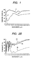
- Fig. 1 is a view which shows the results of measurements of the infrared radiation ratios of the energization heater embodying the present invention and the energization heater conventionally in use, which represents a referential example.
- the measurements are made by use of the Fourier Transform Infrared Spectrometer (hereinafter referred to as an FT-IR device).
- the energization heater (heating means) whose characteristics are indicated by the curved line A is used for the present invention.
- This heater is formed by the provision of the complex oxide film containing Si, Fe, Zr, Ti, and Mn on the surface of the so-called ceramic heater.
- the energization heater whose characteristics are indicated by the curved line B is formed by a ceramic heater having Zr oxide film on the surface thereof, and is conventionally used as a far infrared radiation device.
- the one whose characteristics are indicated by the curved line C is an infrared lamp.
- Each of the curved lines is shown in the form of radiant spectrum per wavelength on condition that the size of each heater is made to be mountable on the FT-IR device.
- the DC1 is applied at 9V and 4A so as to set the surface temperatures thereof at 156°C, and that with the region whose infrared wavelength is 2 ⁇ m to 35 ⁇ m being set at the same temperature of a sample, the ratio between the intensity of infrared radiation of the sample and that of the ideal black object is defined as the radiation ratio ⁇ .
- the specific power is supplied, and the measurement is made in the same manner as described above.
- the radiation ratio of the conventional heater which is indicated by the curved line B, is lower in the shorter wavelength side, and its peak arrives at around 12 ⁇ m.
- the radiation characteristics of the infrared lamp, which is indicated by the curved line C are different from those of the ceramic heaters greatly. At 2 ⁇ m, the peak of the radiation ratio is present, and then, the distribution thereof is parabolic. There is almost no radiation ratio at the wavelength of 5 ⁇ m or more.
- Figs. 2A and 2B are the graphs which illustrate the results of measured infrared absorption characteristics (the so-called infrared absorption spectra) of the heated objects by use of the FT-IR device.
- Fig. 2B shows the three spectra represented in Fig. 2A altogether.
- the curved line A indicates the IR spectrum of ink composed of water soluble dyes C.I, food black 23%, and H 2 O for the remaining portion;
- B the IR spectrum of the recording paper sheet prepared in the form of KBr tablet after the ordinary paper sheet for office use is powered;
- C the IR spectrum of ink composed of oil dyes C.I, solvent black 33%, and ethyl acetate for the remaining portion.
- the infrared absorption of ink presents its main absorption at around 2.8 ⁇ m and 6.3 ⁇ m.
- the former is brought by the H-H stretching vibration, and the latter, by the H-O-H deformation vibration.
- the infrared absorption spectrum of the recording paper sheet presents the intensive absorption within a range of approximately 3 ⁇ m to 11 ⁇ m.
- the infrared rays are absorbed by both ink and paper sheet at around 3 ⁇ m, but at around 6 ⁇ m, the infrared rays are more absorbed by ink, and less by paper sheet. Also, it is clear that at around 10 to 11 ⁇ m, the infrared rays are more absorbed by paper sheet than ink.
- intensive absorption by non-water ink is present at 5.8 ⁇ m and at 7.5 to 8.3 ⁇ m.
- the infrared absorption by ink is greater at around 5.8 ⁇ m, while the infrared rays are absorbed both by paper sheet and ink at around 7.5 to 8.3 ⁇ m.
- the factor that determines the infrared absorption spectra is mainly controlled by solvent. As shown at A and B, the infrared absorption spectra are generally applicable both to water ink and non-water ink. Also, as to recording paper sheet, if it is for use of ink jet recording, its infrared absorption approximates the infrared absorption spectrum at B.
- the wavelength range of less than 4 ⁇ m is the one where the absorption of ink and that of paper sheet are overlaid.
- the infrared rays within this range is capable of heating both ink and paper sheet.
- heat given to ink is generated by the infrared energy that has passed paper sheet after heating paper sheet.
- the energy generated in the heating source is not used efficiently for heating ink.
- the absorption by paper sheet is more intensive. Therefore, ink adhering to paper sheet does not absorb infrared rays more (the infrared rays tend to transmit ink).
- the wavelength range of a heating source so as to provide its peak waveform at the maximum point of the energy distribution at 4 to 10 ⁇ m.
- the combination of each of the heated objects at A and B, and at C and B presents the following:
- ideal heating means is the one that can provide a better thermal action on recording liquid or ink with which to from images (such as to suppress spreading, to prevent color mixture, to enable colorants to produce better colors). Also, there is an upper limit of heating temperature with respect to a recording material. As a result, if ink should be heated indirectly from the recording material, there is also a limit as to the heating effect accordingly. With this in view, the inventors hereof have arrived at the conclusion that ideal heating means can be materialized only in the case of the X described above where the characteristics of infrared radiation of a heating source can be arranged to agree with those of the infrared absorption by ink.
- the energization heater is structured in the same manner as a thermal head.
- a substrate such as alumina, glass
- a pattern formed as a resistor by a conductor such as gold (Au), silver (Ag), platinum (Pt), palladium (Pd) or a compound thereof.
- a resin layer such as polyimide, having a lower rate of thermal transfer between the resistor and the substrate. It is preferable to design the resistor pattern so that the temperature distribution of the heater becomes smaller in the longitudinal and width directions.
- a protection layer for the surface of the resistor by use of glass or some other ceramic coating so that the inner resistor is prevented from abrasion, erosion, shocks, or the like.
- the thickness of the protection layer and the material thereof are selected depending on the design specification, such as temperature, heat response, among some other factors.
- the energization heater of the present embodiment is an infrared radiation device which is capable of radiating the spectrum having its peak waveform of the maximum radiation ratio within a range of the wavelength 4 to 10 ⁇ m.
- the infrared radiation film is provided for the surface layer of the energization heater.
- This layer arrangement may be a film that contains oxide of two or more kinds of elements selected from among the element group given below or may be an oxide film that contains carbon and one or more kinds of elements selected from among the element group given below. It is more preferable that the protection layer itself is a film that contains the above-mentioned oxide. Mg, Al, Si, Ti, Cr, Mn, Fe, Co, Ni, Cu, Zr.
- the element such as Si or Fe, Zr
- the main component element is contained at least 40 wt% or more, and then, other elements are selected in order to enhance the infrared radiation ratio and to adjust the wavelength that indicates the maximum radiation ratio.
- the element group is designated, but there is no influence exerted on the effect thereof even if the film may contain impurity elements included in a film formation material.
- the film is formed by burning after coating a mixed paste, which is prepared by mixing each of metallic fine resin pastes, on the substrate in a specific ratio by means of screen process printing, spraying, spin coating, or the like.
- the above-mentioned film may be formed on a protection layer made of glass or the like. If the thickness of the film is up to approximately 100 ⁇ m, its heat efficiency is not affected unfavorably. Therefore, it is advisable to adopt the inexpensive ceramic heater conventionally in use. In other words, the material used for the present invention may be coated on the surface of the conventional heater.
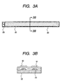
- Figs. 3A and 3B show such an example, the description of which will be made hereunder.
- Fig. 3A is a plan view which shows an energization heater structured as described above.
- Fig. 3B is a cross-sectional view taken along line 3B - 3B in Fig. 3A.
- a reference numeral 20 designates a heat generating resistor pattern formed by an alloy of Ag-Pd; 22, an alumina substrate whose thickness is 0.6 mm; 23, electrodes; 50, an infrared radiation film used for the present embodiment; and 51, a protection layer made of fusion glass.
- the infrared radiation film used for the present embodiment is formed on the surface of the conventional heater, hence making it possible to produce the energization heater that demonstrates the effect of the present embodiment at lower costs.
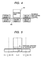
- Fig. 4 is a view which illustrates the anticipated effects obtainable when various heating means are combined in many ways on the basis of the thought described above. In Fig.
- Heating means B is positioned to face a recording head. Any other positions of heating means than that of B are those where no projection of the recording head 401 is possible. It is assumed that these heating means are positioned in the horizontal direction at equal intervals to each other. Also, all the heating means are the same and are arranged to be in contact with the recording sheet 402 (sheet for copying use).
- heating means A to E are divided into one location, two locations, three locations, four locations, and five locations, respectively, and heating is given at the same temperature in any one of the locations.
- characters are recorded on it by means of an ink jet recording head. Recorded characters are observed in enlargement to examine the quality of recorded characters and classify them into five ranks, such as 1, 2, 3, 4, and 5 (5 for the best), in order of those showing better quality.
- those means which provide the quality ranks of 4 and 5 are the following three:
- the surface temperature of heating means B is set at 60°C to 300°C by every 10°C. Recording is then performed in each condition in order to obtain the temperature T5 at which recorded characters present the rank 5. Under this condition, the T5 is 180°C. Further, with the heating performances of (L) and (M) in the heating positions A, B, and D, the surface temperature of each heating means is arranged to change within a specific temperature range centering on T5, thus ranking the quality of recorded characters. In this way, the relationship between the surface temperature of each heating means and the quality of recorded characters is ascertained for each combination of heating positions in (K), (L), and (M), respectively.
- the temperature in the heating position D is made 100°C or more, moisture in the recording paper sheet is evaporated to bring about dew condensation on the reverse side of the sheet. Then, water droplets tend to adhere to it. In some cases, the adhering water droplets may drop off from the reverse side of the sheet onto the surface of the apparatus, hence damaging the interior of the printer. Therefore, the upper limit should be set for the heating temperature in the heating position D so that no water droplets are generated.
- heating position B heating is given from the reverse side of paper sheet.
- moisture in the recording paper sheet and ink is evaporated to the surface side of the paper sheet, and then, with the provision of an appropriate exhausting means, generated vapors are exhausted.
- the possibility of dew condensation in the interior of the printer is much smaller.
- part of generated vapors may adhere to the surface of the recording head.
- this vapor adhesion can be removed by means of the head wiping mechanism.
- vapors adhering to the interior of nozzles of the recording head may supply water to ink in the fine nozzles.
- this adhesion contributes to preventing the ink component from being solidified in the nozzles due to heating.
- this heating position is the best of all to be selected for maintaining the recording reliability.
- the surface temperature of the heating means B should be at the T5 or more.
- the surface temperature of the heating means B should be at T5 or more and the surface temperature of the heating means A should be at less than the T5.
- the surface temperature of the heating means B should be at the T5 or more and the surface temperature of the heating means D should be at less than the T5.
- the temperature of the heating means A or the heating means D may be set at far less than the T5 within a range that satisfies the relationship described above if the obtainable heating area can be obtained large enough, because this arrangement contributes to controlling the amount of moisture contained in a recording sheet constantly, as well as to keeping recording paper sheets in a specific size constantly.
- the temperature should be at the T5 or more. If the heating means A and B are combined or heating means B and D are combined, it should be controlled so that the relationship between the respective surface temperatures maintains B ⁇ A or D.
- the temperature T5 varies depending on the kinds of recording materials, the kinds of ink, and the ratio of shooting amounts of ink. In any case, however, it should be controlled so as not to allow the temperature to cause any thermal decomposition of the recording material irrespective of the heating positions.
- the above-mentioned ceramic heater is used as the energization heater.
- the heating means A or heating means C, D, E it should be good enough if only a specific temperature is obtainable. Therefore, there is no restriction on the heating methods. This is because, in the positions other than B, if only the recording sheet is effectively dried, it should be sufficient.
- the conventional art that adopts the hot plate heating, hot air heating, radiant heating, or the combination of these heating methods is still applicable.
- each arrangement of the heating means A, B, C, D, E is determined in consideration of the measures required to deal with the radiant heat given to the recording head, or in accordance with the width of a recording head, the recording speeds, the recording densities, the amount of ink discharge, the amount of solvent in ink, the permeating speed of ink into the paper sheet, the viscosity of ink, among some other factors.
- the heating means B its position is supposed to face the recording head, but it may be possible to offset the position of the energization heater either to the heating means C side or the heating means A side from the center of the recording head so as not to allow the radiant heat from the heater to be irradiated directly onto the recording head.
- the heating width of the energization heater should be more than 1/2 of the recording width of the recording head (if divisional recording is performed by use of multiple path, the recording width should be for one divisional portion), and it is preferable to position the heater so that more than 1/2 of the recording width should be overlapped with the heating width of the energization heater when these widths are projected.
- the heating width of the energization heater should be more than 1/2 of the recording width of the recording head (if divisional recording is performed by use of multiple path, the recording width should be for one divisional portion), and it is preferable to position the heater so that more than 1/2 of the recording width should be overlapped with the heating width of the energization heater when these widths are projected.
- the heating effect is recognizable if the condition is made to be - 1/2 dh ⁇ Ic ⁇ 1/2 dh.
- the heating effect is recognizable at the condition of - 1/2 dh ⁇ Ic 1/2 dh.
- the heating effect is recognizable at the condition of - dh ⁇ Ic ⁇ dh.
- no heating effect is recognizable at any one of the heating positions.
- the heating means A and D, and the heating means C and E are auxiliary means to enhance the image quality by the application of heat. Therefore, it is unnecessary for them to be face each other. Also, if the energization heaters are incorporated integrally on the substrate as the heating means A and B, and the heating means B and C, the heating distance to the recording sheet becomes longer. As a result, it is made possible to secure the flatness of the recording sheet, hence obtaining a higher effect on the improvement of ink coloring. The costs of manufacture are also made lower accordingly.
- optimization is attempted by the following techniques in consideration of the infrared radiation characteristics of the energization heater.
- An energization heater is installed within a distance where the radiant intensity of infrared rays from the heater is not attenuated, while supporting a recording paper sheet or other recording material in contact.
- a device that can support the recording material in contact it is preferable to arrange the one which is in the mode of netting, for example, and at the same time, it can be heated uniformly over the entire recording region.
- such supporting device should be conditioned so that it does not catch the tip or the leading end of the recording material while it is in progress, and that the device itself is not heated to raise its temperature for the safety (skin burning prevention).
- the supporting device in the form of screen grid provided with a number of apertures having an opening angle in the moving direction of the recording paper sheet.
- the opening angle of the aperture portion is set at 45° as standard to the line of the moving direction of the recording paper sheet, and then, the length of the longer side of the aperture portion should be designed to be approximately 2 1/2 times the recording width of the recording head (the numbers of discharge openings n / recording density dpi).
- Fig. 6 is a plan view which shows a preferred screen grid embodying the present invention.
- the screen grid shown in Fig. 6 is formed by SUS 304 having a plate thickness of 0.1 mm, which is ground until the surface roughness becomes 1.0 ⁇ m or less.
- an arrow ( ⁇ ) indicates the traveling direction of the recording paper sheet.
- the aperture portion 80 is formed by means of etching to be symmetrical to the left and right from the center of the screen grid.
- the opening angle 81 of the aperture portion 80 is 43°.
- the width 82 of the grid is 0.4 mm.
- the configuration of the aperture portion 80 is not necessary quadrangular. It may be egg-shaped.
- Fig. 7 is a detailed view which shows a screen grid having the egg-shaped aperture portion.
- This grid is formed by SUS 304 whose plate thickness is 0.1 mm. It is ground until the surface roughness becomes 1.0 ⁇ m or less.
- an arrow ( ⁇ ) indicates the traveling direction of the recording paper sheet.
- the aperture portion 83 is formed by means of etching to be symmetrical to the left and right from the center of the screen grid.
- the opening angle 84 of the aperture portion 83 is 45°.
- the width 85 of the grid is 0.4 mm.
- the surface of the screen grid and the edge of the aperture portion thereof shown in Fig. 6 and Fig. 7 should be processed by means of grinding, etching, or the like to smooth its contour so that the contact friction with the recording paper sheet is made as small as possible. It is preferable to form the screen grid by stainless steel, coated steel plate, or the like. Then, in order to avoid the temperature rise of the screen grid itself, its surface is finished mirror like to make its infrared radiation ratio 0.1 or less. In other words, the arrangement is made so that most of the infrared rays should be reflected. If the screen grid is formed by such material and in such configuration, it is possible to fulfill the safety requirement described earlier.
- the experiments are conducted to examine the characteristics of the temperature rise with respect to the screen grid shown in Fig. 6.
- the screen grid shown in Fig. 6 is installed in a position which is 0.35 mm apart from the energization heater embodying the present invention. Then, in the environment at the room temperature of 25°C, the energization heater is energized to maintain the surface temperature at 170°C. In this condition, the surface temperature of the screen grid is kept at 50°C constantly. It is thus confirmed that the infrared radiation ratio is made effectively 0.1 or less.
- one sample screen grid is made by rolled stainless steel plate in the same configuration as the one shown in Fig. 6, but the surface of the screen grid is not processed to be glossy.
- This comparison grid is placed under the same environment. Then, when the surface temperature of the energization heater arrives at 170°C, the temperature of this sample screen grid is raised to 140°C. As a result, image unevenness takes place, and the problem of safety is encountered.
- the energization heater that embodies the present invention When the energization heater that embodies the present invention is used in a position that faces a recording head, the moment water ink adheres to the recording paper sheet, the deformation (cockling) of the recording paper sheet takes place.
- the ink jet recording head is installed with a gap of approximately 1 mm to the surface of the recording material. Then, if the cockling is excessive, the surface of the recording head and the recording material are in contact with each other, making it difficult to discharge ink normally in some cases.
- a guide that presses the recording paper sheet from above, while assisting the transfer thereof, in a position that faces the device for supporting the recording material in contact, but does not interfere the operation of the recording head.
- the guide It is preferable to form the guide with a flat plate in a configuration so as to press the entire width of the recording paper sheet. It is also preferable to configure the end portion of the guide with the edge having a number of waveforms provided with opening angle in the traveling direction of the recording paper sheet rather than to make it straight line. This is because, as in the screen grid described earlier, the recording paper sheet should not be caught by the guide, and also because with such configuration of the guide, the generation of irregular cockling should be suppressed.
- the material of the guide is not necessarily confined, but it is preferable to use the one whose infrared radiation ratio is 0.1 or less like the screen grid in consideration of the case where heating is given before the recording position (for example, if the structure is arranged as in the heating means D and B, it is possible to reduce the degree of cooling that may occur during the carrying period of the recording paper sheet that has been heated by heating means D to the recording position where heating means B is located).
- the specific example of the guide is shown in Fig. 8.
- Fig. 8 shows the guide arranged in a position that faces the device that supports a recording material, which assists the transfer of the recording material.
- This guide is formed by SUS 304 whose plate thickness is 0.1 mm, and ground until the surface roughness thereof becomes 1.0 ⁇ m or less.
- the opening angle of the edge 97 of the guide is 45°.
- Various recording media can be the object of an ink jet recording apparatus. It is required to obtain the best result of recording under any recording condition.
- the heating fixation is mainly aimed at allowing only the colorant of dyes contained in ink to remain on a recording paper sheet as much as possible.
- the inventors hereof have found that by the combination of the amount of recording liquid to be given to a recording material per unit time (hereinafter referred to the ratio R of shooting amount of ink) together with the required electric power for heating, a specific temperature can be controlled and set appropriately, and that with such control, the best result of printing is obtainable under any recording condition. On the basis of such finding, the inventors hereof have established this combination as a method for controlling the temperature of an energization heater.
- a condition is defined so that the moment discharge is made, ink adheres to a recording paper sheet, and that the moment ink adheres to the recording paper sheet, it is all transformed into vapor (here, the volume which is equivalent to thermal work is defined as J, and the heat efficient to ink, as ⁇ ).
- the heat efficiency ⁇ is defined by (absorbed energy) / (input energy).
- the absorbed energy is distributed to ink and paper sheet, and ink is heated by heat that has passed the paper sheet. Therefore, the rise of ink temperature ⁇ the temperature rise of the paper sheet.
- the maximum heating efficiency on ink is 50%.
- T (Ws) between the heating power Ws and the surface temperature of the energization heater has been obtained separately, and then, recording should be performed in condition that the temperature Tr is determined uniquely by the ratio Rs of shooting amount of ink.
- N 64
- F 10 kHz
- 4V 3 ⁇ 10 -8 ml
- n 1.0
- T 25°C
- ⁇ 0.5
- the ratio Rs of shooting amount of ink 0.0192 ml/sec.
- the heating power Ws 98.9 W.
- the relationship T(W L ) between the W L and the surface temperature of the energization heater should be obtained separately for the full-line printer, and recording should be performed in condition that the temperature Tr is determined uniquely by the R L .
- the above example of calculation is for an ordinary paper as a recording material.
- recording materials other than the ordinary paper such as transparent film, coated paper, or glossy paper, which has different characteristics of ink absorption from those of the ordinary paper sheet, recording becomes better by setting the different temperatures for the heater. Therefore, the temperatures of the heater can be appropriately set in accordance with the materials of the recording media.
- the temperature functions Tr are obtained for various ratios R of shooting amounts of ink. Further, the temperature designations are combined in accordance with the kinds of recording materials. Then, such information is stored in ROM or the like on the driving circuit of the energization heater as a table of control conditions. In this manner, it is made possible to perform recording in the best heating condition in accordance with a recording material and printing mode designated by means of the printer driver or the like installed in an ink jet recording apparatus.
- an energization heater having electrical resistance of 15 ⁇ is incorporated in a printer BJC-610 (manufactured by Canon Inc.: provided with a recording head of 360 dpi, 64 nozzles; the amount of discharge, 30 pl; the driving frequency, 6 kHz; and water color ink used).
- the gap between the recording paper sheet and the energization heater is set at 0.35 mm.
- the enhancement of image quality is observed (such as suppression of spreading and bleeding, and improvement of optical concentration).
- the surface temperature of the energization heater at that time is 170°C.
- the conventional heat fixing means heat is transferred to ink through a recording paper sheet that has been heated. Therefore, there is a need for giving heat excessively, and only in the heating condition where the solvent (water) in ink may be evaporated completely, it is possible to enhance the image quality good enough.
- the energization heater embodying the present invention has a higher heating efficiency on ink, and as compared with the conventional heater, it is possible to save energy more than 50%.
- the heat fixing means embodying the present invention has an enhanced characteristics of the infrared absorption with respect to ink of the recorded object. It is understandable that since the above-mentioned effect of this means is higher than that of the conventional one, it can improve the image quality with use of a smaller amount of energy. As a result, the heating fixation means of the present invention demonstrates a sufficient effect even without evaporating moisture completely, hence making it possible to design the unit of heating means compactly, and to make the printer smaller accordingly.
- the image quality can be enhanced sufficiently even without evaporating solvent (moisture) completely. Therefore, if an exhaust fan should be provided, it is still possible to minimize its structure for the effective use of the fan.
- Fig. 9 As the driving circuit of the energization heater, one example may be cited as shown in Fig. 9, which is represented in the form of a block diagram.
- a reference numeral 10 designates an energization heater; 11, a power source; 12, a temperature control circuit; 13, a temperature controller; 14, temperature detection means; 15, a CPU for use of printer control; and 16, the safety device of the energization heater (which will be described later in detail).
- the power source 11 may be for an alternate current supply or for a direct current supply. However, it is preferable that the capacitance of the power source has a marge of approximately 10% to the maximum power dissipation.
- the temperature control circuit 12 is the ROM that stores the temperature control conditions described above. On the ROM, there are stored not only the operational temperatures of the energization heater in recording, but also, such information as the heating conditions on the printing standby before a printing command is given; power information required for raising the heater to a given temperature when a printing command is issued; the control temperature between one recording paper sheet and another during a continuous recording; and information required for selecting heating means in a particular position, among some others. On the basis of such information, the CPU 15 performs the temperature control of the energization heaters.
- any type of temperature controller 13 can be adopted if only the controller is able to on and off the load in accordance with the external signals.
- Temperature detection means is to sense the surface temperatures of the energization heater. This means may be formed by a thermo couple, a thermistor, or the like.
- the CPU 15 selects the optimum heating condition from the temperature control circuit (ROM) in according with the contents carried by the signals thus provided.
- the CPU 15 supplies the required power from the power source 11 to the energization heater 10.
- the On-Off control of the power source 11 is controlled through the temperature controller 13.
- the CPU 15 monitors the temperatures of the energization heater 10 in accordance with signals being transmitted from temperature detection means 14.
- the CPU transmits the sheet feeding signal to a sheet carrier device (not shown), thus transferring the recording paper sheet to the recording region. Then, the CPU 15 transmits recording signals to the recording head (not shown) to start printing.
- the CPU 15 controls to heat the energization heater 10 in the warm air condition stored on the temperature control circuit 12.
- the CPU 12 also heats the energization heater in accordance with the information of power rising stored on the temperature control circuit 12. Then, when it is confirmed that the temperature of the heater has arrived at the predetermined one in accordance with signals from the temperature detection means, the CPU controls the ON-OFF of the power supply from the power source 11 to the energization heater 10 through the temperature controller 12, hence keeping the operational temperature constantly in recording.
- the CPU 15 reads the warm air condition from the temperature control circuit 12 for determining whether the power required for the warm air operation should be supplied to the energization heater 10 or the power supply to the energization heater should be suspended.
- the heater has potentially the danger that if the control of the apparatus is disabled, the heater is caused to be runaway; the apparatus may be damaged by an abrupt raise of temperature caused by the thermal damage given to the recording paper sheet that may reside on the heater due to jamming of the recording paper sheet; or fire may break out in the worst case.
- a safety device is effectively adoptable.
- the heater itself with means for cutting off electric current or a mechanism to cut off electric current by means of an external circuit when the temperature rises more than a specific temperature or a complex means having them together.
- a temperature fuse 21 is arranged on a part of the resistor pattern 20 of the heater.
- the temperature fuse works when heater temperature rises abruptly due to disabled control.
- a part of the temperature fuse is formed by thick film to make the area of thermal sensitivity larger.
- a reference numeral 22 designates an alumina substrate of the energization heater, and 23, electrodes for supplying electric power.
- a temperature fuse is used for the device that necessitates the supply of a large power for charging such device. Therefore, it is difficult to make the response time shorter before fusing the temperature fuse.
- the temperature fuse 21 it is preferable to use Sn, solder, or some other metal or an alloy having a lower fusion point.
- the fusion temperature is based on the maximum temperature adopted by the energization heater, and it is desirable to set the fusion temperature slightly higher than such maximum temperature.
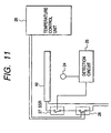
- Fig. 11 is a block diagram which shows the structure of the safety device installed outside the apparatus.
- a reference numeral 24 designates an infrared photosensor; 25, a detection circuit; 26, a temperature controller; 27, SSR (solid state relay); 28, magnetic clutch; and 10, an energization heater.
- the detection circuit 25 transforms into voltage the electric current that runs through the infrared photosensor 24 which changes in proportion to the amount of light received.
- the temperature control unit 26 determines that the energization heater is in operation when the detected voltage is smaller than a specific value. If any abnormal rise of temperature takes place when the temperature control unit 26 recognizes the supply of electric power to the energization heater, such abnormal rise of temperature is sensed immediately by the infrared photosensor 24.
- the detection circuit 25 transfers the voltage higher than the normally detected voltage to the temperature control unit 26. Having received such voltage, the temperature control unit 26 operates as given below.
- the temperature control unit 26 When the temperature control unit 26 receives a voltage higher than the normal detection voltage, this unit turns off the magnetic clutch 28 which is directly connected with the power supply line of the energization heater 10. The power supply to the energization heater 10 is then cut off to prevent it from being runaway.
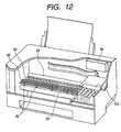
- a reference numeral 30 designates an energization heater installed in the position that faces a recording head 100.
- This heater has the infrared radiation characteristics indicated by the curved line in Fig. 1.
- the energization heater 30 is formed on an alumina substrate of 10 mm width, and 0.6 mm thick, having on it the AG - Pd resistor pattern and Si 55, Fe 18, Zr 15, Ti 8, and Mn (wt %) on such pattern. Its electric resistance is 15 ⁇ . The maximum power dissipation is 35 W.
- the energization heater can demonstrate the heat fixing effect up to the throughput of four A4-sized full color images per minute.
- a reference numeral 32 designates a screen grid formed by SUS 304 whose plate thickness is 0.1 mm; 33, a guide formed by the same material as the screen grid 32; 34, paper sheet carrier means formed in the rubber roller configuration; 35, an auxiliary guide with star wheels that carries the recording paper sheet; and 36, a unit formed by the driving circuit and temperature control unit whose specific structures are the same as those shown in Fig. 9.
- Fig. 13 is a cross-sectional view which shows the recording head 100, the energization heater 30, the screen grid 32, the guide 33, the rubber roller 34, and the star wheeled guide 35, and the relative positional relationship between them as well.
- the ink jet recording apparatus embodying the present invention can demonstrate various effects as described above.
- the fundamental characteristics are such that heat is well absorbed by ink efficiently, while it is not easily absorbed by recording paper sheets, because the infrared radiation characteristics of the energization heater used therefor has its maximum value within a range of 4 to 10 ⁇ m.
- an ordinary paper sheet is placed on the energization heater, and then, the temperature is raised to the one at which the color of the paper changes. However, no color change occurs in three minutes. After that, the recording paper sheet is left intact. Then, although its color changes, no burning nor smoking takes place. Meanwhile, the same experiment is conducted on the energization heater having the conventional infrared radiation characteristics. Then, color change begins in 30 seconds. After that, as the recording paper sheet is left intact, smoking begins to present a dangerous state.
- the recording apparatus of the present embodiment is provided with the sufficient safety measure in order to avoid the runaway of the energization heater, but the energization heater itself has a lower heating efficiency on paper. As a result, the safety of the apparatus is more improved.
- Fig. 14 is a cross-sectional view which shows the structure of an ink jet recording apparatus in accordance with a second embodiment of the present invention.
- the present embodiment is such that a sheet heater 37 is further installed in a position before recording in addition to the first embodiment shown in Fig. 12, and that the recording paper sheet is heated by this heater from the reverse side thereof.
- Any other structures of the present embodiment are the same as those of the embodiment shown in Fig. 12.
- the preventive effect on the thermal deformation of the recording paper sheet is more enhanced than that of the first embodiment.
- Fig. 15 is a cross-sectional view which shows the structure of an ink jet recording apparatus in accordance with a third embodiment of the present invention.
- a halogen lamp heater 38 is installed in a position after recording in addition to the first embodiment shown in Fig. 12 in order to heat the recording paper sheet from the reverse side thereof.
- the obtainable image quality is equal to that of the first embodiment
- the dryness of prints after recording is higher than that of the first embodiment. Also, the deformation thereof is smaller.
- Fig. 16 is a cross-sectional view which shows the structure of an ink jet recording apparatus in accordance with a fourth embodiment of the present invention.
- two energization heaters 39 and 40 are arranged in parallel with the same pattern as shown in Fig. 10, which are formed on an alumina substrate of 40 mm width and 0.6 mm thick as in the first embodiment shown in Fig. 12.
- the energization heater 39 is positioned to face the recording head 100.
- the energization heater 40 is positioned after recording and heats the recording paper sheet from the reverse side thereof.
- the other structures of the present embodiment are the same as those of the embodiment shown in Fig. 12.
- the same effects as the third embodiment can be demonstrated, that is, the obtainable image quality is the same as that of the first embodiment, but the dryness of prints after recording is higher than that of the first embodiment. Also, the deformation thereof is smaller. In accordance with the present embodiment, it is possible to make the recording apparatus smaller than that of the third embodiment.
- Fig. 17 is a cross-sectional view which shows the structure of an ink jet recording apparatus in accordance with a fifth embodiment of the present invention.
- the present embodiment is such that a sheet heater 41 is in a position before recording to heat the recording paper sheet from the surface side thereof, and that an energization heater 42 having the same structure as that of the first embodiment is installed in a position that faces the recording head. Any other structures of the present embodiment are the same as those of the embodiment shown in Fig. 12.
- the preventive effect on the thermal deformation of the recording paper sheet is more enhanced than that of the first embodiment.
- Fig. 18 is a cross-sectional view which shows the structure of an ink jet recording apparatus in accordance with a sixth embodiment of the present invention.
- a ceramic heater 46 is installed in a position after recording to heat the recording paper sheet from the surface thereof, and an energization heater 30 having the same structure as that of the first embodiment is installed in the position that faces the recording head. Any other structures are the same as those of the embodiment shown in Fig. 12.
- the obtainable image quality is equal to that of the first embodiment
- the dryness of prints after recording is higher than that of the first embodiment when the ink whose permeability is smaller is used.
- the prevention effect on the thermal deformation of the recording paper sheet is higher than that of the first embodiment.
- Fig. 19 is a cross-sectional view which shows the structure of an ink jet recording apparatus in accordance with a seventh embodiment of the present invention.
- two energization heaters 43 and 44 are arranged in parallel, each having the same structure as that of the first embodiment.
- the energization heaters 43 and 44 are made a unit in a length larger than the width of an A1-sized recording sheet by 10 mm each on the left and right sides.
- the power dissipation of the energization heaters 43 and 44 are 300 W. Each of them can be controlled individually.
- a reference numeral 45 designate a screen grid for use of a larger sized sheet. In accordance with the present embodiment, it is possible to obtain a high quality recording of the larger-sided sheet, such as the Al size, without creating any cockling and unevenness.
- the ink jet recording apparatus is capable of optimizing the characteristics of the infrared radiation given to the energization heaters, as well as optimizing the heating positions and temperature control thereof, in order to obtain recorded images in the best condition at all the time. Therefore, the ink jet recording apparatus can demonstrate excellent heating fixation effects as given below with a high safety arrangement.
- the ink jet recording apparatus demonstrates such effects as to effectuate a high coloring without smaller amount of spread, and to suppress bleeding for the reduction of cockling. As a result, the quality of recorded images is enhanced.
- the power dissipation is lower to make the capacitance of the power supply smaller. Also, with the smaller numbers of attachment, such as reflection plate, the heater unit can be made smaller accordingly. Therefore, this heating fixation arrangement is applicable to a smaller sized printer for personal use.
- the apparatus can demonstrate high heating effects on water ink, and non-water ink as well.
- An ink jet recording apparatus for recording by discharging recording liquid droplets from the discharge openings to a recording material for the adhesion of the liquid droplets on the recording material for the formation of images includes the carrier path for carrying the recording material, heating means arranged for the carrier path to heat the recording material and recording liquid.
- This heating means is provided with a heater having radiation characteristics with the peak waveform of the maximum value within a range of radiated infrared radiation ratio ⁇ of 4 ⁇ m to 10 ⁇ m wavelength.
Landscapes
- Health & Medical Sciences (AREA)
- General Health & Medical Sciences (AREA)
- Toxicology (AREA)
- Ink Jet (AREA)
- Particle Formation And Scattering Control In Inkjet Printers (AREA)
Claims (17)
- Tintenstrahlaufzeichnungsgerät zum Aufzeichnen durch das Ausstoßen von aufzeichnenden Flüssigkeitströpfchen aus den Ausstoßöffnungen eines Aufzeichnungskopfes (100) auf ein Aufzeichnungsmaterial für die Haftung der flüssigen Tröpfchen auf dem Aufzeichnungsmaterial für die Herausbildung von Bildern weist auf:dadurch gekennzeichnet, daßeine Beförderungsbahn (32, 34, 45) für die Beförderung des Aufzeichnungsmaterials,eine Heizvorrichtung (20, 30, 37, 39, 40, 41, 42, 43, 44, 46, A, B, C, D, E) angeordnet für die Beförderungsbahn (32, 34, 45), um das Aufzeichnungsmaterial und die Aufzeichnungstinte zu erhitzen,eine Heizvorrichtung (20, 30, 37, 39, 40, 41, 42, 43, 44, 46, A, B, C, D, E), die einen Heizer aufweist,
der Heizer eine Strahlungscharakteristik mit einer Hauptwellenform aufweist, deren maximaler Wert innerhalb eines Bereiches des ausgestrahlten Infrarotstrahlungsverhältnisses ε von 4 µm bis 10 µm liegt. - Tintenstrahlaufzeichnungsgerät gemäß Anspruch 1, wobei der Heizer (20, 30, 37, 39, 40, 43, 44, A, B, C) in einer Position angeordnet ist, um das Aufzeichnungsmaterial und die Aufzeichnungstinte von der umgekehrten Seite der Aufzeichnungsoberfläche des Aufzeichnungsmaterials zu beheizen.
- Tintenstrahlaufzeichnungsgerät gemäß Anspruch 1 oder Anspruch 2, wobei ein Stützelement (32, 45), das aus einem Material besteht, das ein geringeres Infrarotstrahlungsverhältnis ε aufweist, angeordnet ist, um das Aufzeichnungsmaterial in einer Position zu halten, in der es der Heizer erwärmen kann.
- Tintenstrahlaufzeichnungsgerät gemäß Anspruch 1, wobei die Oberflächentemperatur des Heizers (20, 30, 37, 39, 40, 43, 44, A, B, C) für das Beheizen des Aufzeichnungsmaterials die Temperatur ist, die durch die Kombination der Art des Aufzeichnungsmaterials und der Menge der für das Aufzeichnungsmaterial pro Zeiteinheit bereitgestellten Aufzeichnungsflüssigkeit festgelegt wird.
- Tintenstrahlaufzeichnungsgerät gemäß Anspruch 1, wobei die vom Heizer (20, 30, 37, 39, 40, 43, 44, A, B, C) beheizte Heizbreite ½ oder mehr von der vom Aufzeichnungskopf (100) aufgezeichneten Aufzeichnungsbreite beträgt, weiterhin ist der Heizer (20, 30, 37, 39, 40, 43, 44, A, B, C) in einer Lage positioniert, die es ermöglicht, daß ½ oder mehr der Aufzeichnungsbreite von der Heizbreite in der Projektion überlappt werden.
- Tintenstrahlaufzeichnungsgerät gemäß Anspruch 1, wobei der Heizer (20, 30, 37, 39, 40, 43, 44, A, B, C) mit einem Film bedeckt ist, der zwei oder mehr Arten Oxidelemente enthält, die aus der Elementgruppe Mg, Al, Si, Ti, Cr, Mn, Fe, Co, Ni, Cu, Zr ausgewählt sind.
- Tintenstrahlaufzeichnungsgerät gemäß Anspruch 1, wobei der Heizer (20, 30, 37, 39, 40, 43, 44, A, B, C) mit einem Oxidfilm bedeckt ist, der Kohlenstoff und eine oder mehr Arten von Elementen enthält, die aus der Elementgruppe Mg, Al, Si, Ti, Cr, Mn, Fe, Co, Ni, Cu, Zr ausgewählt sind.
- Tintenstrahlaufzeichnungsgerät gemäß Anspruch 1, wobei der Heizer (20, 30, 37, 39, 40, 43, 44, A, B, C) mit einer Vorrichtung (21) für die selbsttätige Unterbrechung des für das Heizen verwendeten elektrischen Stromes ausgestattet ist, falls die Temperatur des Heizers selbst eine bestimmte Temperatur übersteigt.
- Tintenstrahlaufzeichnungsgerät gemäß Anspruch 1, wobei ein Abschalt-Schaltkreis angeordnet ist, um den elektrischen Strom zum Heizer (20, 30, 37, 39, 40, 43, 44, A, B, C) für das Heizen zu unterbrechen, wenn die Temperatur des Heizers (20, 30, 37, 39, 40, 43, 44, A, B, C) eine bestimmte Temperatur übersteigt.
- Tintenstrahlaufzeichnungsgerät gemäß Anspruch 3, wobei das Element (32, 45), welches das Aufzeichnungsmaterial trägt, ein gitterartiges, flaches Blech ist, das mit einer Anzahl von Öffnungen versehen ist, die einen Öffnungswinkel zur Beförderungsrichtung des Aufzeichnungsmaterials haben.
- Tintenstrahlaufzeichnungsgerät gemäß Anspruch 10, wobei das Infrarotstrahlungsverhältnis ε des Elementes (32, 45), welches das Aufzeichnungsmaterial trägt, 0,1 oder weniger beträgt.
- Tintenstrahlaufzeichnungsgerät gemäß Anspruch 3, wobei eine Leitvorrichtung (Fig. 8), die aus einem ebenen Blech gebildet ist, die eine Anzahl gewellter Kanten mit einem Öffnungswinkel in der Bewegungsrichtung des Aufzeichnungsmaterials aufweist, in einer Position gegenüber dem Element (32, 45) angeordnet ist, um das Aufzeichnungsmaterial abzustützen oder die Beförderung des Aufzeichnungsmaterials zu unterstützen.
- Tintenstrahlaufzeichnungsgerät gemäß Anspruch 12, wobei das Infrarotstrahlungsverhältnis ε der Leitvorrichtung 0,1 oder weniger beträgt.
- Tintenstrahlaufzeichnungsgerät gemäß allen vorangehenden Ansprüchen, wobei der Heizer in einer Position gegenüber dem Aufzeichnungskopf angeordnet ist.
- Tintenstrahlaufzeichnungsgerät gemäß allen vorangehenden Ansprüchen, wobei besagter Heizer der erste Heizer ist und ein zweiter Heizer eine Strahlungscharakteristik besitzt, die sich von der des ersten Heizers unterscheidet, wobei
der erste Heizer in einer dem Aufzeichnungskopf gegenüberliegenden Position angeordnet ist
der zweite Heizer in einer Position angeordnet ist, um das Aufzeichnungsmaterial vor und/oder nach der Aufzeichnung zu beheizen. - Tintenstrahlaufzeichnungsgerät gemäß Anspruch 15, wobei die Oberflächentemperatur des ersten Heizers größer ist als die Oberflächentemperatur des zweiten Heizers für die Erhitzung des Aufzeichnungsmaterials vor der Aufzeichnung, und gleichzeitig überschreiten die beiden Oberflächentemperaturen des Heizers und des zweiten Heizers nicht die Zersetzungstemperatur, die eine Verformung des Aufzeichnungsmaterials verursachen würde.
- Tintenstrahlaufzeichnungsverfahren zum Erzeugen von Bildern, das einen Aufzeichnungskopf (100) verwendet für das Ausstoßen von aufzeichnenden Flüssigkeitströpfchen aus den Ausstoßöffnungen für die Erzeugung von Bildern durch die Haftung der aufzeichnenden Flüssigkeitströpfchen auf dem Aufzeichnungsmaterial, wobei das Verfahren folgende Schritte aufweist:Erzeugen von Bildern durch die Haftung der aufzeichnenden Flüssigkeitströpfchen auf dem Aufzeichnungsmaterial, undErhitzen des Aufzeichnungsmaterials und der aufzeichnenden Flüssigkeitströpfchen durch die Verwendung von Infrarotstrahlen, die eine Strahlungscharakteristik mit einer Hauptform des Strahlungsverhältnisses ε mit einem maximalen Wert innerhalb des Wellenlängenbereiches von 4 µm oder mehr und 10 µm oder weniger aufweisen.
Applications Claiming Priority (6)
| Application Number | Priority Date | Filing Date | Title |
|---|---|---|---|
| JP7163897 | 1997-03-25 | ||
| JP71638/97 | 1997-03-25 | ||
| JP7163897 | 1997-03-25 | ||
| JP10065215A JPH10323974A (ja) | 1997-03-25 | 1998-03-16 | インクジェット記録方法と装置、及び該装置に用いられる定着発熱体 |
| JP65215/98 | 1998-03-16 | ||
| JP6521598 | 1998-03-16 |
Publications (3)
| Publication Number | Publication Date |
|---|---|
| EP0867301A2 EP0867301A2 (de) | 1998-09-30 |
| EP0867301A3 EP0867301A3 (de) | 1999-11-03 |
| EP0867301B1 true EP0867301B1 (de) | 2004-12-22 |
Family
ID=26406341
Family Applications (1)
| Application Number | Title | Priority Date | Filing Date |
|---|---|---|---|
| EP98105309A Expired - Lifetime EP0867301B1 (de) | 1997-03-25 | 1998-03-24 | Tintenstrahlaufzeichnungsgerät und Fixier-Heizelement für solch ein Gerät |
Country Status (6)
| Country | Link |
|---|---|
| US (1) | US6244700B1 (de) |
| EP (1) | EP0867301B1 (de) |
| JP (1) | JPH10323974A (de) |
| KR (1) | KR100312952B1 (de) |
| CN (1) | CN1103697C (de) |
| DE (1) | DE69828212T2 (de) |
Families Citing this family (49)
| Publication number | Priority date | Publication date | Assignee | Title |
|---|---|---|---|---|
| US6435117B2 (en) * | 1998-05-01 | 2002-08-20 | L&P Property Management Company | Printing and quilting method and apparatus |
| US6592223B1 (en) * | 1999-10-07 | 2003-07-15 | Panaseca, Inc. | System and method for optimal viewing of computer monitors to minimize eyestrain |
| JP2001186880A (ja) * | 1999-10-22 | 2001-07-10 | Ngk Insulators Ltd | Dnaチップの製造方法 |
| US6656432B1 (en) * | 1999-10-22 | 2003-12-02 | Ngk Insulators, Ltd. | Micropipette and dividedly injectable apparatus |
| US6983687B2 (en) * | 2001-04-10 | 2006-01-10 | Mccoy William E | Method for custom imprinting plastic identifier tags |
| JP2003072059A (ja) * | 2001-06-21 | 2003-03-12 | Ricoh Co Ltd | インクジェット記録装置及び複写機 |
| US7270407B2 (en) * | 2001-06-29 | 2007-09-18 | Hewlett-Packard Development Company, L.P. | Methods for digitally printing on ceramics |
| US7069858B2 (en) * | 2001-10-04 | 2006-07-04 | Dennis Apana | Method for custom imprinting plastic identifier tags |
| GB2387449B (en) * | 2002-04-08 | 2006-06-07 | Nordson Uv Ltd | Lamp control system |
| US20040189769A1 (en) * | 2003-03-31 | 2004-09-30 | Oce Display Graphics Systems, Inc. | Methods, systems, and devices for drying ink deposited upon a medium |
| US20050036023A1 (en) * | 2003-08-12 | 2005-02-17 | Xerox Corporation | Printer architecture with upper paper trays |
| US7137694B2 (en) | 2003-09-29 | 2006-11-21 | Hewlett-Packard Development Company, L.P. | Ink drying system for printer |
| JP2005161583A (ja) * | 2003-11-28 | 2005-06-23 | Brother Ind Ltd | 布帛への白色インクジェット画像形成方法及び装置 |
| US7449662B2 (en) * | 2004-04-26 | 2008-11-11 | Hewlett-Packard Development Company, L.P. | Air heating apparatus |
| NZ532931A (en) * | 2004-05-14 | 2007-12-21 | Allflex New Zealand | Improvements in animal identification marking |
| US20050259981A1 (en) * | 2004-05-21 | 2005-11-24 | Eastman Kodak Company | Apparatus and method of removing carrier from a recording element |
| US20060021537A1 (en) * | 2004-07-29 | 2006-02-02 | Kazuhiko Ohtsu | Curing method of cure type liquid composition and inkjet recording apparatus |
| US7700158B2 (en) * | 2004-10-20 | 2010-04-20 | Royal Canadian Mint | Method of printing an image on a metallic surface, particularly on a coin surface |
| US20060102032A1 (en) * | 2004-10-29 | 2006-05-18 | Peow Ng | Heating system for printing apparatus |
| JP2006212787A (ja) * | 2005-02-01 | 2006-08-17 | Canon Inc | インクジェット記録装置 |
| US7461925B2 (en) * | 2005-03-04 | 2008-12-09 | Hewlett-Packard Development Company, L.P. | Adjusting power |
| EP1707388B1 (de) | 2005-03-29 | 2012-05-16 | Seiko Epson Corporation | Tintenstrahlaufzeichnungsgerät mit einem Heizgerät |
| JP5098140B2 (ja) * | 2005-09-22 | 2012-12-12 | コニカミノルタエムジー株式会社 | インクジェット記録装置 |
| JP2007202818A (ja) * | 2006-02-02 | 2007-08-16 | Univ Osaka Sangyo | マイクロ波を利用した加熱皺伸ばし装置 |
| JP2008068462A (ja) * | 2006-09-13 | 2008-03-27 | Ricoh Co Ltd | 紙の乾燥工程を設けたインクジェット記録方法及び記録装置、並びにそのためのインク |
| US7793117B2 (en) * | 2006-10-12 | 2010-09-07 | Hewlett-Packard Development Company, L.P. | Method, apparatus and system for determining power supply to a load |
| US7832852B2 (en) * | 2007-07-16 | 2010-11-16 | Xerox Corporation | Continuous media web heater |
| JP5020293B2 (ja) * | 2009-07-29 | 2012-09-05 | 株式会社ミヤコシ | 電子写真印刷機 |
| US8646899B2 (en) | 2010-05-28 | 2014-02-11 | Hewlett-Packard Development Company, L.P. | Methods and apparatus for ink drying |
| JP5442550B2 (ja) * | 2010-07-16 | 2014-03-12 | 富士フイルム株式会社 | インクジェット記録装置 |
| JP5578676B2 (ja) * | 2010-09-29 | 2014-08-27 | 富士フイルム株式会社 | 液滴吐出装置および制御不能イジェクタの配線切断方法 |
| JP5235977B2 (ja) * | 2010-12-16 | 2013-07-10 | 富士フイルム株式会社 | 画像形成装置及び画像形成方法 |
| JP5673082B2 (ja) | 2010-12-24 | 2015-02-18 | セイコーエプソン株式会社 | 記録装置 |
| US8534825B2 (en) | 2011-02-11 | 2013-09-17 | Xerox Corporation | Radiant heater for print media |
| JP5772382B2 (ja) * | 2011-08-16 | 2015-09-02 | セイコーエプソン株式会社 | 記録装置 |
| JP2013208754A (ja) | 2012-03-30 | 2013-10-10 | Brother Industries Ltd | カール矯正機構を備えた液体吐出装置及びカール矯正方法 |
| JP6102385B2 (ja) * | 2013-03-19 | 2017-03-29 | セイコーエプソン株式会社 | 記録装置 |
| JP6132094B2 (ja) * | 2013-07-23 | 2017-05-24 | セイコーエプソン株式会社 | 記録装置 |
| JP6135857B2 (ja) * | 2013-07-29 | 2017-05-31 | セイコーエプソン株式会社 | 乾燥方法 |
| JP6454955B2 (ja) * | 2013-09-11 | 2019-01-23 | 株式会社リコー | 乾燥装置、画像形成装置及び制御装置 |
| US10442184B2 (en) * | 2015-04-30 | 2019-10-15 | Hewlett-Packard Development Company, L.P. | Dryers for printed media |
| JP6645274B2 (ja) * | 2016-03-04 | 2020-02-14 | セイコーエプソン株式会社 | 印刷装置 |
| JP2018103366A (ja) * | 2016-12-22 | 2018-07-05 | セイコーエプソン株式会社 | 印刷装置 |
| DE102017107920A1 (de) * | 2017-04-12 | 2018-10-18 | Heraeus Noblelight Gmbh | Druckmaschine mit einer Infrarot-Trocknereinheit |
| JP6369702B2 (ja) * | 2017-04-27 | 2018-08-08 | セイコーエプソン株式会社 | 乾燥方法 |
| WO2018199954A1 (en) * | 2017-04-27 | 2018-11-01 | Hewlett-Packard Development Company, L.P. | Sequencing of loads using temperature |
| JP7056209B2 (ja) * | 2017-09-26 | 2022-04-19 | 富士フイルムビジネスイノベーション株式会社 | 吐出装置 |
| JP7437988B2 (ja) * | 2020-03-24 | 2024-02-26 | 株式会社Screenホールディングス | インクジェット印刷装置及びその制御方法 |
| JP7600845B2 (ja) * | 2021-04-22 | 2024-12-17 | コニカミノルタ株式会社 | 画像形成装置 |
Family Cites Families (20)
| Publication number | Priority date | Publication date | Assignee | Title |
|---|---|---|---|---|
| DE2600832A1 (de) | 1976-01-12 | 1977-07-21 | Torsten Schmidt | Verfahren und vorrichtung zum trocknen von drucksachen |
| JPS57120447A (en) | 1981-01-20 | 1982-07-27 | Matsushita Electric Ind Co Ltd | Ink-jet recording device |
| US4517893A (en) * | 1982-07-28 | 1985-05-21 | Planet Products Corporation | Silk screen printing with the curing of polymerizable liquids |
| GB2141072B (en) | 1983-04-21 | 1986-08-20 | Arthur Roland Palmer | Ink drying apparatus |
| JPS60964A (ja) * | 1983-06-17 | 1985-01-07 | Mitsubishi Heavy Ind Ltd | 印刷紙の乾燥装置 |
| GB8520367D0 (en) | 1985-08-14 | 1985-09-18 | Palmer A R | Heater/dryer apparatus |
| US4774523A (en) | 1987-03-25 | 1988-09-27 | Hewlett-Packard Company | Method and apparatus for uniformly drying ink on paper from an ink jet printer |
| JPH02182461A (ja) | 1989-01-06 | 1990-07-17 | Seiko Epson Corp | インクジェット記録装置 |
| US4978969A (en) * | 1989-07-05 | 1990-12-18 | Hewlett-Packard Company | Method for printing using ultra-violet curable ink |
| GB8922058D0 (en) | 1989-09-29 | 1989-11-15 | T R H Jackson Ltd | Electric heater |
| US5020244A (en) | 1989-12-01 | 1991-06-04 | International Business Machines Corporation | Method and apparatus for drying liquid on printed media |
| EP0568174B1 (de) | 1992-05-01 | 1996-09-18 | Hewlett-Packard Company | Heizgebläseanordnung in einem Farbstrahldrucker |
| US5479199A (en) | 1992-05-01 | 1995-12-26 | Hewlett-Packard Company | Print area radiant heater for ink-jet printer |
| US5668584A (en) * | 1992-05-01 | 1997-09-16 | Hewlett-Packard Company | Method of multiple zone heating of inkjet media using screen platen |
| JP2941119B2 (ja) | 1992-06-05 | 1999-08-25 | キヤノン株式会社 | インクジェット記録装置 |
| US5896154A (en) * | 1993-04-16 | 1999-04-20 | Hitachi Koki Co., Ltd. | Ink jet printer |
| US5631685A (en) | 1993-11-30 | 1997-05-20 | Xerox Corporation | Apparatus and method for drying ink deposited by ink jet printing |
| JP3302177B2 (ja) | 1994-05-27 | 2002-07-15 | キヤノン株式会社 | インクジェット記録方法及び記録装置 |
| JP3317322B2 (ja) | 1995-03-24 | 2002-08-26 | セイコーエプソン株式会社 | インクジェット記録装置 |
| US5754208A (en) * | 1995-11-27 | 1998-05-19 | Xerox Corporation | Liquid ink printer having dryer with integral reflector |
-
1998
- 1998-03-16 JP JP10065215A patent/JPH10323974A/ja active Pending
- 1998-03-23 US US09/045,687 patent/US6244700B1/en not_active Expired - Lifetime
- 1998-03-24 EP EP98105309A patent/EP0867301B1/de not_active Expired - Lifetime
- 1998-03-24 DE DE69828212T patent/DE69828212T2/de not_active Expired - Lifetime
- 1998-03-25 KR KR1019980010283A patent/KR100312952B1/ko not_active Expired - Fee Related
- 1998-03-25 CN CN98105877A patent/CN1103697C/zh not_active Expired - Fee Related
Also Published As
| Publication number | Publication date |
|---|---|
| US6244700B1 (en) | 2001-06-12 |
| DE69828212D1 (de) | 2005-01-27 |
| DE69828212T2 (de) | 2005-12-15 |
| CN1249997A (zh) | 2000-04-12 |
| CN1103697C (zh) | 2003-03-26 |
| JPH10323974A (ja) | 1998-12-08 |
| KR19980080646A (ko) | 1998-11-25 |
| EP0867301A2 (de) | 1998-09-30 |
| KR100312952B1 (ko) | 2002-04-17 |
| EP0867301A3 (de) | 1999-11-03 |
Similar Documents
| Publication | Publication Date | Title |
|---|---|---|
| EP0867301B1 (de) | Tintenstrahlaufzeichnungsgerät und Fixier-Heizelement für solch ein Gerät | |
| EP0568272B1 (de) | Vorheizwalze für einen thermischen Tintenstrahldrucker | |
| JP3329882B2 (ja) | インクジェット・プリンタ | |
| JP3330422B2 (ja) | インクジェット・プリンタ及びヒータ・スクリーン | |
| EP0568174B1 (de) | Heizgebläseanordnung in einem Farbstrahldrucker | |
| EP0568256B1 (de) | Luftströmungssystem für einen thermischen Tintenstrahldrucker | |
| JP3420830B2 (ja) | インクジェットプリンタ | |
| EP0622194A1 (de) | Heizstrahler für die Druckfläche für einen Tintenstrahldrucker | |
| EP0635370B1 (de) | Ein Tintendrucksystem | |
| JPH06320813A (ja) | インクジェットプリンタ | |
| US6827435B2 (en) | Moving air jet image conditioner for liquid ink | |
| JP4357796B2 (ja) | 定着装置および画像形成装置 | |
| JPH08132724A (ja) | インクジェット記録方法およびその装置 | |
| JP2606190B2 (ja) | インクジエツト記録装置 | |
| JP2004074415A (ja) | インクジェットプリンタの乾燥装置 | |
| JPH06218913A (ja) | 転写媒体 | |
| EP4434757B1 (de) | Tintenstrahlaufzeichnungsgerät mit endlosem trockenband | |
| JPH10230592A (ja) | ソリッドインクジェットプリンタ |
Legal Events
| Date | Code | Title | Description |
|---|---|---|---|
| PUAI | Public reference made under article 153(3) epc to a published international application that has entered the european phase |
Free format text: ORIGINAL CODE: 0009012 |
|
| AK | Designated contracting states |
Kind code of ref document: A2 Designated state(s): DE ES FR GB IT NL |
|
| AX | Request for extension of the european patent |
Free format text: AL;LT;LV;MK;RO;SI |
|
| PUAL | Search report despatched |
Free format text: ORIGINAL CODE: 0009013 |
|
| AK | Designated contracting states |
Kind code of ref document: A3 Designated state(s): AT BE CH DE DK ES FI FR GB GR IE IT LI LU MC NL PT SE |
|
| AX | Request for extension of the european patent |
Free format text: AL;LT;LV;MK;RO;SI |
|
| RIC1 | Information provided on ipc code assigned before grant |
Free format text: 6B 41J 11/00 A, 6B 41F 23/04 B |
|
| 17P | Request for examination filed |
Effective date: 20000322 |
|
| AKX | Designation fees paid |
Free format text: DE ES FR GB IT NL |
|
| 17Q | First examination report despatched |
Effective date: 20030311 |
|
| GRAP | Despatch of communication of intention to grant a patent |
Free format text: ORIGINAL CODE: EPIDOSNIGR1 |
|
| GRAS | Grant fee paid |
Free format text: ORIGINAL CODE: EPIDOSNIGR3 |
|
| GRAA | (expected) grant |
Free format text: ORIGINAL CODE: 0009210 |
|
| AK | Designated contracting states |
Kind code of ref document: B1 Designated state(s): DE ES FR GB IT NL |
|
| PG25 | Lapsed in a contracting state [announced via postgrant information from national office to epo] |
Ref country code: NL Free format text: LAPSE BECAUSE OF FAILURE TO SUBMIT A TRANSLATION OF THE DESCRIPTION OR TO PAY THE FEE WITHIN THE PRESCRIBED TIME-LIMIT Effective date: 20041222 Ref country code: IT Free format text: LAPSE BECAUSE OF FAILURE TO SUBMIT A TRANSLATION OF THE DESCRIPTION OR TO PAY THE FEE WITHIN THE PRE;WARNING: LAPSES OF ITALIAN PATENTS WITH EFFECTIVE DATE BEFORE 2007 MAY HAVE OCCURRED AT ANY TIME BEFORE 2007. THE CORRECT EFFECTIVE DATE MAY BE DIFFERENT FROM THE ONE RECORDED.SCRIBED TIME-LIMIT Effective date: 20041222 Ref country code: FR Free format text: LAPSE BECAUSE OF FAILURE TO SUBMIT A TRANSLATION OF THE DESCRIPTION OR TO PAY THE FEE WITHIN THE PRESCRIBED TIME-LIMIT Effective date: 20041222 Ref country code: ES Free format text: LAPSE BECAUSE OF FAILURE TO SUBMIT A TRANSLATION OF THE DESCRIPTION OR TO PAY THE FEE WITHIN THE PRESCRIBED TIME-LIMIT Effective date: 20041222 |
|
| REG | Reference to a national code |
Ref country code: GB Ref legal event code: FG4D |
|
| REF | Corresponds to: |
Ref document number: 69828212 Country of ref document: DE Date of ref document: 20050127 Kind code of ref document: P |
|
| PG25 | Lapsed in a contracting state [announced via postgrant information from national office to epo] |
Ref country code: GB Free format text: LAPSE BECAUSE OF NON-PAYMENT OF DUE FEES Effective date: 20050324 |
|
| NLV1 | Nl: lapsed or annulled due to failure to fulfill the requirements of art. 29p and 29m of the patents act | ||
| PLBE | No opposition filed within time limit |
Free format text: ORIGINAL CODE: 0009261 |
|
| STAA | Information on the status of an ep patent application or granted ep patent |
Free format text: STATUS: NO OPPOSITION FILED WITHIN TIME LIMIT |
|
| GBPC | Gb: european patent ceased through non-payment of renewal fee |
Effective date: 20050324 |
|
| 26N | No opposition filed |
Effective date: 20050923 |
|
| EN | Fr: translation not filed | ||
| PGFP | Annual fee paid to national office [announced via postgrant information from national office to epo] |
Ref country code: DE Payment date: 20140331 Year of fee payment: 17 |
|
| REG | Reference to a national code |
Ref country code: DE Ref legal event code: R119 Ref document number: 69828212 Country of ref document: DE |
|
| PG25 | Lapsed in a contracting state [announced via postgrant information from national office to epo] |
Ref country code: DE Free format text: LAPSE BECAUSE OF NON-PAYMENT OF DUE FEES Effective date: 20151001 |