EP0858896A2 - Dispositif d'impression à jet d'encre et procédé d'impression utilisant cette dispositif - Google Patents
Dispositif d'impression à jet d'encre et procédé d'impression utilisant cette dispositif Download PDFInfo
- Publication number
- EP0858896A2 EP0858896A2 EP98301085A EP98301085A EP0858896A2 EP 0858896 A2 EP0858896 A2 EP 0858896A2 EP 98301085 A EP98301085 A EP 98301085A EP 98301085 A EP98301085 A EP 98301085A EP 0858896 A2 EP0858896 A2 EP 0858896A2
- Authority
- EP
- European Patent Office
- Prior art keywords
- ink jet
- ink
- liquid
- ejection ports
- ejected
- Prior art date
- Legal status (The legal status is an assumption and is not a legal conclusion. Google has not performed a legal analysis and makes no representation as to the accuracy of the status listed.)
- Granted
Links
Images


Classifications
-
- B—PERFORMING OPERATIONS; TRANSPORTING
- B41—PRINTING; LINING MACHINES; TYPEWRITERS; STAMPS
- B41J—TYPEWRITERS; SELECTIVE PRINTING MECHANISMS, i.e. MECHANISMS PRINTING OTHERWISE THAN FROM A FORME; CORRECTION OF TYPOGRAPHICAL ERRORS
- B41J2/00—Typewriters or selective printing mechanisms characterised by the printing or marking process for which they are designed
- B41J2/005—Typewriters or selective printing mechanisms characterised by the printing or marking process for which they are designed characterised by bringing liquid or particles selectively into contact with a printing material
- B41J2/01—Ink jet
- B41J2/015—Ink jet characterised by the jet generation process
- B41J2/04—Ink jet characterised by the jet generation process generating single droplets or particles on demand
- B41J2/045—Ink jet characterised by the jet generation process generating single droplets or particles on demand by pressure, e.g. electromechanical transducers
- B41J2/04501—Control methods or devices therefor, e.g. driver circuits, control circuits
- B41J2/04503—Control methods or devices therefor, e.g. driver circuits, control circuits aiming at compensating carriage speed
-
- B—PERFORMING OPERATIONS; TRANSPORTING
- B41—PRINTING; LINING MACHINES; TYPEWRITERS; STAMPS
- B41J—TYPEWRITERS; SELECTIVE PRINTING MECHANISMS, i.e. MECHANISMS PRINTING OTHERWISE THAN FROM A FORME; CORRECTION OF TYPOGRAPHICAL ERRORS
- B41J2/00—Typewriters or selective printing mechanisms characterised by the printing or marking process for which they are designed
- B41J2/005—Typewriters or selective printing mechanisms characterised by the printing or marking process for which they are designed characterised by bringing liquid or particles selectively into contact with a printing material
- B41J2/01—Ink jet
- B41J2/015—Ink jet characterised by the jet generation process
- B41J2/04—Ink jet characterised by the jet generation process generating single droplets or particles on demand
- B41J2/045—Ink jet characterised by the jet generation process generating single droplets or particles on demand by pressure, e.g. electromechanical transducers
- B41J2/04501—Control methods or devices therefor, e.g. driver circuits, control circuits
- B41J2/04516—Control methods or devices therefor, e.g. driver circuits, control circuits preventing formation of satellite drops
-
- B—PERFORMING OPERATIONS; TRANSPORTING
- B41—PRINTING; LINING MACHINES; TYPEWRITERS; STAMPS
- B41J—TYPEWRITERS; SELECTIVE PRINTING MECHANISMS, i.e. MECHANISMS PRINTING OTHERWISE THAN FROM A FORME; CORRECTION OF TYPOGRAPHICAL ERRORS
- B41J2/00—Typewriters or selective printing mechanisms characterised by the printing or marking process for which they are designed
- B41J2/005—Typewriters or selective printing mechanisms characterised by the printing or marking process for which they are designed characterised by bringing liquid or particles selectively into contact with a printing material
- B41J2/01—Ink jet
- B41J2/015—Ink jet characterised by the jet generation process
- B41J2/04—Ink jet characterised by the jet generation process generating single droplets or particles on demand
- B41J2/045—Ink jet characterised by the jet generation process generating single droplets or particles on demand by pressure, e.g. electromechanical transducers
- B41J2/04501—Control methods or devices therefor, e.g. driver circuits, control circuits
- B41J2/04526—Control methods or devices therefor, e.g. driver circuits, control circuits controlling trajectory
-
- B—PERFORMING OPERATIONS; TRANSPORTING
- B41—PRINTING; LINING MACHINES; TYPEWRITERS; STAMPS
- B41J—TYPEWRITERS; SELECTIVE PRINTING MECHANISMS, i.e. MECHANISMS PRINTING OTHERWISE THAN FROM A FORME; CORRECTION OF TYPOGRAPHICAL ERRORS
- B41J2/00—Typewriters or selective printing mechanisms characterised by the printing or marking process for which they are designed
- B41J2/005—Typewriters or selective printing mechanisms characterised by the printing or marking process for which they are designed characterised by bringing liquid or particles selectively into contact with a printing material
- B41J2/01—Ink jet
- B41J2/015—Ink jet characterised by the jet generation process
- B41J2/04—Ink jet characterised by the jet generation process generating single droplets or particles on demand
- B41J2/045—Ink jet characterised by the jet generation process generating single droplets or particles on demand by pressure, e.g. electromechanical transducers
- B41J2/04501—Control methods or devices therefor, e.g. driver circuits, control circuits
- B41J2/04573—Timing; Delays
-
- B—PERFORMING OPERATIONS; TRANSPORTING
- B41—PRINTING; LINING MACHINES; TYPEWRITERS; STAMPS
- B41J—TYPEWRITERS; SELECTIVE PRINTING MECHANISMS, i.e. MECHANISMS PRINTING OTHERWISE THAN FROM A FORME; CORRECTION OF TYPOGRAPHICAL ERRORS
- B41J2/00—Typewriters or selective printing mechanisms characterised by the printing or marking process for which they are designed
- B41J2/005—Typewriters or selective printing mechanisms characterised by the printing or marking process for which they are designed characterised by bringing liquid or particles selectively into contact with a printing material
- B41J2/01—Ink jet
- B41J2/015—Ink jet characterised by the jet generation process
- B41J2/04—Ink jet characterised by the jet generation process generating single droplets or particles on demand
- B41J2/045—Ink jet characterised by the jet generation process generating single droplets or particles on demand by pressure, e.g. electromechanical transducers
- B41J2/04501—Control methods or devices therefor, e.g. driver circuits, control circuits
- B41J2/0458—Control methods or devices therefor, e.g. driver circuits, control circuits controlling heads based on heating elements forming bubbles
-
- B—PERFORMING OPERATIONS; TRANSPORTING
- B41—PRINTING; LINING MACHINES; TYPEWRITERS; STAMPS
- B41J—TYPEWRITERS; SELECTIVE PRINTING MECHANISMS, i.e. MECHANISMS PRINTING OTHERWISE THAN FROM A FORME; CORRECTION OF TYPOGRAPHICAL ERRORS
- B41J2/00—Typewriters or selective printing mechanisms characterised by the printing or marking process for which they are designed
- B41J2/005—Typewriters or selective printing mechanisms characterised by the printing or marking process for which they are designed characterised by bringing liquid or particles selectively into contact with a printing material
- B41J2/01—Ink jet
- B41J2/21—Ink jet for multi-colour printing
- B41J2/2107—Ink jet for multi-colour printing characterised by the ink properties
- B41J2/2114—Ejecting transparent or white coloured liquids, e.g. processing liquids
Definitions
- the present invention relates to an ink jet print apparatus and method for ejecting inks to form ink liquid droplets and depositing them on a printing medium such as paper for printing, and in particular, to a configuration for preventing an ink jet head from inappropriately ejecting inks due to the splashing of ejected liquid droplets occurring on the printing medium.
- ink jet print apparatuses Due to the use of non-impact printing method, ink jet print apparatuses have various advantages such as low noise during printing and fast printing and are gathering attention due to their ability to provide significantly saturated color images.
- ink jet print apparatuses which use thermal energy to eject inks, since the ink jet head can be manufactured using processes similar to those for semiconductor devices, the size of the apparatus can be easily reduced, while the number and density of orifices used can be easily increased.
- a plurality of types of inks for example, yellow, magenta, cyan, and black corresponding to colors to be printed are generally ejected from heads for the respective inks in such a way that these inks are deposited on one another substantially at the same position of the printing medium in order to form desired color dots.
- the present applicant has proposed a print apparatus that ejects a processing liquid (also referred to as a printing quality improvement liquid) that makes the color material in an ink insoluble or aggregation in such a way that the liquid is deposited on the ink.
- a processing liquid also referred to as a printing quality improvement liquid
- This configuration can mix the ink with the processing liquid on the printing medium to make the color material such as a dye in the ink insoluble in order to improve water-proofness. It can also prevent the ink from bleeding and increase the concentration to improve the print grade.
- a subsequent ink or the processing liquid deposits in a overlay manner on a liquid droplet of an ink or the processing liquid that is precedently deposited on the printing medium and that is permeating therein, so splashing is more likely to occur and a larger amount of liquid droplets splashes than a case an ink droplet is deposited on the printing medium without depositing a precedent or leading ink.
- Such splashing droplets or processing liquid droplets, or splashing liquid droplets into which an ink and the processing liquid are mixed together deposit on the face (in which ejection ports are disposed) of the ink jet head like mists, thereby deflecting the ejection direction or preventing ejection to affect the grade of images.
- the first object is to provide an ink jet print apparatus for printing and can be achieved by one aspect of this invention using an ink jet head that ejects a liquid from at least two ejection ports to allow liquids sequentially ejected from the at least two ejection ports as the ink jet head and a printing medium are relatively moved to deposit on the printing medium in such a way that the liquids are deposited on one another on the printing medium, wherein a velocity vector of the liquid ejected from at least one of the at least two ejection ports has a component of the velocity vector in the direction opposite to the relative moving direction of the ink jet head and the printing medium.
- the velocity vector of a subsequent one of the liquids sequentially ejected from the at least two ejection ports may have a larger component of the velocity vector in the direction opposite to the relative moving direction than a velocity vector component of a leading liquid.
- the second object is to provide an ink jet print apparatus for printing and can be achieved by a second aspect of this invention using an ink jet head that ejects a liquid from at least two ejection ports in order to allowing liquids sequentially ejected from the at least two ejection ports as the ink jet head and a printing medium are relatively moved to deposit on the printing medium in such a way that the liquids are deposited on one another on the printing medium, wherein a velocity vector of the liquid ejected from at least one of the at least two ejection ports has a component of the velocity vector in the direction opposite to the relative moving direction of the ink jet head and the printing medium.
- the velocity vector of a subsequent one of the liquids sequentially ejected from the at least two ejection ports may have a larger component of the velocity vector in the direction opposite to the relative moving direction than a velocity vector of a leading liquid.
- At least one of the velocity vectors of the liquids sequentially ejected from the at least two ejection ports in the ink jet head as the ink jet head is scanned has a component of the velocity vector in the direction opposite to the relative moving direction.
- the direction in which the subsequently ejected liquid is ejected can be tilted toward the direction opposite to the relative moving direction relative to the printing medium, thereby enabling a splashing liquid droplet caused by the depositing on an already deposited liquid droplet of the subsequent liquid droplet, to be directed away from the ink jet head.
- FIG. 1 shows an ink jet cartridge that can be installed in an ink jet print apparatus according to this invention and that consists of an ink jet head and an ink tank.
- FIG. 2 is a perspective view showing in a partial cross section a portion relating to one of ejection port arrays in the ink jet head shown in FIG. 1.
- FIG. 3 is a perspective view showing an ink jet print apparatus in which the ink jet cartridge is detachably mounted.
- an ink jet cartridge 10 comprises an ink jet head 3 and ink tank 5 that are integrally formed.
- the ink jet head 3 has two ejection port arrays; each ejection port 1B in one of the arrays ejects a black ink while the each ejection port 1S in the other array ejects a processing liquid (also referred to a "printing quality improvement liquid") that makes the dye in the black ink insoluble or aggregation. That is, the ink jet head 3 is structurally divided into two parts each of which is driven for independent ejection.
- the ink tank 5 has two chambers therein for storing, for example, a black ink and the processing liquid.
- FIG. 2 shows in detail the structure of that portion of the ink jet head 3 shown in FIG. 1 which ejects the black ink, and the portion for ejecting the processing liquid has a similar structure.
- An ink supplied from the ink tank 5 is filled in the common liquid chamber 20 each ink path 9 which is provided corresponding to each ejection port 1BK and supplied to the ink path 9 for ejection from a common liquid chamber 20 as the ink is ejected.
- a print signal that is, an electric signal from a head drive circuit is applied to a heater 7 via an electrode 8, and then the heater 7 is heated to apply thermal energy to the ink present in the ink path 9 near the heater 7.
- the application of thermal energy subjects the ink to film boiling to generate bubbles, the pressure of which causes the ink to be ejected from the ejection port 1BK.
- the ejection port 1BK is structured in such a way that an ink ejection direction V'3 is at a predetermined angle instead of 90° from a face 2. The predetermined angle is described in detail in FIG. 5.
- the processing liquid is ejected using a similar structure and a similar principle.
- the ink jet cartridge is detachably mounted in the ink jet print apparatus shown in FIG. 3. That is, the ink jet cartridge 10 is detachably mounted on a carriage 22, while the carriage 22 can be moved for scanning by means of driving by a carriage motor 24 transmitted via a belt 25 while being guided by two guide shafts 21.
- the carriage 22 mounting the ink jet cartridge 10 thereon is reciprocally scanned in a primary direction along a longitudinal direction of the two guide shafts 21, the carriage 22 and a printing paper P as a printing medium may be relatively moved in the primary direction.
- the print signal is transferred to the ink jet head 10 from an apparatus control section via a flexible printed circuit board 13 and based on this signal, the head is driven as described above and printing is performed through ink ejection.
- the processing liquid deposits on that predetermined position on the printing paper P on which, for example, a black ink droplet deposits.
- the processing liquid does not need to deposit on all specified positions on the printing paper P on which the black ink deposits, specified effects of this invention can be obtained if the black ink droplet is deposited only on some of the depositing positions.
- either the black ink or the processing liquid may be ejected first. In either case, this invention is applicable even if the contents of a splashing liquid droplet are different.
- a recovery pump 12 is connected to the caps 11 to provide a negative pressure in a closed space consisting of the face 2 and the caps 11 in order to suck the ink or processing liquid in the ejection port 1BK and the ink path 9 in communication with the ejection port, thereby performing suction recovery processing that eliminates blinding.
- the two ejection port arrays almost perpendicular to the primary scanning direction are disposed in parallel at an interval of 1.27 cm with the plurality of ejection ports of each array disposed at an interval of 42.5 ⁇ m.
- Fifteen nano-grams per droplet of the processing liquid is ejected from the ejection ports in the first array.
- 30 nano-grams per droplet of the black ink is ejected from the ejection ports in the second array.
- the processing liquid or solution for making ink dyestuff insoluble can be obtained in the following manner.
- the resultant mixture is pressure-filtered with the use of a membrane filter of 0.22 ⁇ m in pore size (tradename : Fuloroporefilter, manufactured by Sumitomo Electric Industries, Ltd.) so that yellow ink Y1, magenta ink M1, cyan ink C1 and black ink K1 can be obtained.
- a membrane filter of 0.22 ⁇ m in pore size (tradename : Fuloroporefilter, manufactured by Sumitomo Electric Industries, Ltd.) so that yellow ink Y1, magenta ink M1, cyan ink C1 and black ink K1 can be obtained.
- the aforementioned processing liquid and ink are mixed with each other at the position on the printing medium or at the position where they penetrate in the printing medium.
- the ingredient having a low molecular weight or cationic oligomer among the cationic material contained in the processing liquid and the water soluble dye used in the ink having anionic radical are associated with each other by an ionic mutual function as a first stage of reaction whereby they are instantaneously separated from the solution liquid phase.
- the aggregated material formed by the ingredient having a low molecular weight or the cationic oligomer of the cationic material and the anionic dye by way of the aforementioned mechanism has increased viscosity.
- the aggregated material does not move as the liquid medium moves, ink dots adjacent to each other are formed by inks each having a different color at the time of forming a full colored image but they are not mixed with each other. Consequently, a malfunction such as bleeding does not occur.
- the aggregated material is substantially water-insoluble, water resistibility of a formed image is complete. In addition, light resistibility of the formed image can be improved by the shielding effect of polymer.
- insoluble or “aggregation” refers to observable events in only the above first stage or in both the first and second stages.
- plain paper such as copying paper, bond paper or the like conventionally used
- coated paper specially prepared for ink jet printing and OHP transparent film are preferably used.
- ordinary high quality paper and bright coated paper can preferably be used.
- the ink jet head 3 is driven at a drive frequency of 9.6 kHz, so if dots are formed at a density of 600 dpi on a printing medium 1.5 mm away from the ink jet head 3 in the primary scanning direction, then at position A in the figure, a processing liquid droplet 16 is ejected from the first ejection port array 14 in the perpendicular direction relative to the head at an ejection velocity V1 (12m/s) and, 125 ⁇ sec later, the liquid droplet deposits at position X on the printing medium P.
- the head is moved over the spacing distance between the first ejection port array 14 and the second ejection port array 15, and at the same position as the first ejection port array 14 that has ejected the processing liquid droplet 16, a black ink droplet 17 is ejected from the second ejection port array 15 in the same direction as the processing liquid droplet at an ejection velocity V1 (12m/s).
- V1 ejection velocity
- FIG. 4 shows the condition of the ejection of the black ink droplet 17 from the second ejection port array 15, and the chain line in FIG. 4 shows the mutual locational relationship between the two ejection port arrays 14 and 15 formed in the face 2 as seen from the printing medium P.
- the moving velocity of the head during printing is 0.4064 m/s, which corresponds to the carriage velocity V2 shown in FIG. 4.
- V1 is an ejection velocity of 12 m/s
- V3 is an ejection velocity and direction relative to the printing medium P which can be obtained by synthesizing the two velocities V1 and V2.
- ⁇ 1.9°, as seen in FIG. 4.
- the splashing droplet 19 deposits on the face 2 of the head 3 that is scanning with a trace shown in the figure.
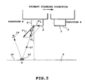
- the resolution, drive condition, and printing density of the ink jet head shown in FIG. 5 and the distance between the head and the printing medium are similar to those shown in FIG. 4.
- the head is moved over the spacing distance between the first ejection port array 14 and the second ejection port array 15, and at the same position as the first ejection port array 14 that has ejected the processing liquid droplet 16, the black ink droplet 17 is ejected from the second ejection port array 15.
- the ejection direction and velocity of the black ink droplet 17 is the same as in the processing liquid droplet 16, so the black ink droplet 17 deposits on the printing medium P at position X at 144 ⁇ sec after the ejection from the second ejection port array 15.
- the ejection direction of the black ink droplet 17 relative to the printing medium P is shown as V'3 in the figure by synthesizing velocity vector components V'1 and V'2 together, and the black ink droplet 17 deposits on the processing liquid droplet 16 at 61.7° relative to the printing medium P at 31250 ⁇ sec after the depositing of the processing liquid droplet.
- This depositing causes the ink splashing droplet to splash at 61.7° relative to the printing medium P, and when the splashing droplet 19 reaches the height of the face 2 of the head, the head 3 has moved to position B that advances 1732 ⁇ m from its original position in the primary scanning direction as shown in FIG. 5, thereby preventing the splashing droplet from depositing on the face 2.
- this embodiment provides the ink jet head having the two ejection port arrays corresponding to the ink and processing liquid wherein the ink splashing direction can be deviated from the face of the head by ejecting the ink droplet and processing liquid droplet so as to have a velocity vector in the direction opposite to the scanning direction of the head and changing the angle at which the ink droplet deposits.
- the splashing ink and processing liquid can be prevented from depositing on the face of the head in order to appropriately reduce the occurrence of ejection errors using the simple configuration.
- the processing liquid droplet 16 is ejected from the first ejection port array 14 in the perpendicular direction relative to the head at an ejection velocity of 12 m/s.
- the droplet 16 deposits at position X on the printing medium P as shown in FIG. 5.
- the ejection angle ( ⁇ in FIG. 5) of the black ink droplet is set at 15.0° so that the black ink droplet is ejected when the head is further moved from the ejection position of the proceeding liquid droplet in the primary scanning direction.
- the head 3 has moved 803.8 ⁇ m from the ejection position of the black ink in the primary scanning direction, thereby preventing the splashing droplet from depositing on the face 2.
- the difference in depositing time between the processing liquid and the black ink at position X of the printing medium P is 32235 ⁇ sec. This depositing time difference is 985 ⁇ sec longer than that in the conventional head or the above embodiment.
- the ejection angle of the black ink droplet ( ⁇ in FIG. 5) is set at 30.0° with the ejection angle of the processing liquid droplet unchanged (perpendicular to the head)
- the head 3 has moved 1732 ⁇ m from the ejection position of the black ink in the primary scanning direction, thereby preventing the splashing droplet from depositing on the face of the ink jet head.
- the difference in depositing time between the processing liquid and the black ink at position X of the printing medium P is 33362 ⁇ sec. This depositing time difference is 2112 ⁇ sec longer than that in the conventional head or the above embodiment.
- the depositing time difference can be increased to correspondingly enable the processing liquid to fully permeate through the printing medium in order to reduce the later splashing of the dot of the depositing black ink droplet.
- the application of this invention is not limited to the use of the processing liquid but this invention is obviously applicable to, for example, a color print apparatus that ejects various inks so that they are deposited on one another.
- Ink usable for carrying out the present invention should not be limited only to dyestuff ink, and pigment ink having pigment dispersed therein can also be used. Any type of processing liquid can be used, provided that pigment is aggregated with it.
- the following pigment ink can be noted as an example of pigment ink adapted to cause aggregation by mixing with the treatment liquid A1 previously discussed.
- yellow ink Y2, magenta ink M2, cyan ink C2 and black ink K2 each containing pigment and anionic compound can be obtained.
- the following materials are poured in a batch type vertical sand mill (manufactured by Aimex Co.), glass beads each having a diameter of 1 mm is filled as media using anion based high molecular weight material P-1 (aqueous solution containing a solid ingredient of styrene methacrylic acid ethylacrylate of 20 % having an acid value of 400 and average molecular weight of 6000, neutralizing agent : potassium hydroxide) as dispersing agent to conduct dispersion treatment for three hours while water-cooling the sand mill. After completion of dispersion, the resultant mixture has a viscosity of 9 cps and pH of 10.0.
- the dispersing liquid is poured in a centrifugal separator to remove coarse particles, and a carbon black dispersing element having a weight-average grain size of 10 nm is produced.
- the final product has a solid ingredient of about 10 %.
- Anionic high molecular P-2 (aqueous solution containing a solid ingredient of 20 % of stylenacrlylic acid methyl methaacrylate having an acid value of 280 and an average molecular weight of 11,000, neutralizing agent : diethanolamine) is used as a dispersing agent and dispersive treatment is conducted in the same manner as production of the black ink K2 whereby yellow color dispersing element having a weight-average grain size of 103 nm is produced.
- the thus obtained yellow dispersing element is sufficiently dispersed in water to obtain yellow ink Y2 for ink jet printing and having pigment contained therein.
- the final product of ink contains a solid ingredient of about 10 %.
- Cyan colored-dispersant element having a weight-average grain size of 120 nm is produced by using the anionic high molecular P-1 used when producing the black ink K2 as dispersing agent, and moreover, using the following materials by conducting dispersing treatment in the same manner as the carbon black dispersing element.
- composition of cyan colored-dispersing element composition of cyan colored-dispersing element
- the thus obtained cyan colored dispersing element is sufficiently stirred to obtain cyan ink C2 for ink jet printing and having pigment contained therein.
- the final product of ink has a solid ingredient of about 9.6 %.
- Magenta color dispersing element having a weight-average grain size of 115 nm is produced by using the anionic high molecular P-1 used when producing the black ink K2 as dispersing agent, and moreover, using the following materials in the same manner as that in the case of the carbon black dispersing agent.
- composition of the magenta colored dispersing element composition of the magenta colored dispersing element
- Magenta ink M2 for ink jet printing and having pigment contained therein is obtained by sufficiently dispersing the magenta colored dispersing element in water.
- the final product of ink has a solid ingredient of about 9.2 %.
- the present invention achieves distinct effect when applied to a recording head or a recording apparatus which has means for generating thermal energy such as electrothermal transducers or laser light, and which causes changes in ink by the thermal energy so as to eject ink. This is because such a system can achieve a high density and high resolution recording.
- the on-demand type apparatus has electrothermal transducers, each disposed on a sheet or liquid passage that retains liquid (ink), and operates as follows: first, one or more drive signals are applied to the electrothermal transducers to cause thermal energy corresponding to recording information; second, the thermal energy induces sudden temperature rise that exceeds the nucleate boiling so as to cause the film boiling on heating portions of the recording head; and third, bubbles are grown in the liquid (ink) corresponding to the drive signals. By using the growth and collapse of the bubbles, the ink is expelled from at least one of the ink ejection orifices of the head to form one or more ink drops.
- the drive signal in the form of a pulse is preferable because the growth and collapse of the bubbles can be achieved instantaneously and suitably by this form of drive signal.
- a drive signal in the form of a pulse those described in U.S. patent Nos. 4,463,359 and 4,345,262 are preferable.
- the rate of temperature rise of the heating portions described in U.S. patent No. 4,313,124 be adopted to achieve better recording.
- U.S. patent Nos. 4,558,333 and 4,459,600 disclose the following structure of a recording head, which is incorporated to the present invention: this structure includes heating portions disposed on bent portions in addition to a combination of the ejection orifices, liquid passages and the electrothermal transducers disclosed in the above patents. Moreover, the present invention can be applied to structures disclosed in Japanese Patent Application Laying-open Nos. 123670/1984 and 138461/1984 in order to achieve similar effects.
- the former discloses a structure in which a slit common to all the electrothermal transducers is used as ejection orifices of the electrothermal transducers, and the latter discloses a structure in which openings for absorbing pressure waves caused by thermal energy are formed corresponding to the ejection orifices.
- the present invention can be also applied to a so-called full-line type recording head whose length equals the maximum length across a recording medium.
- a recording head may consists of a plurality of recording heads combined together, or one integrally arranged recording head.
- the present invention can be applied to various serial type recording heads: a recording head fixed to the main assembly of a recording apparatus; a conveniently replaceable chip type recording head which, when loaded on the main assembly of a recording apparatus, is electrically connected to the main assembly, and is supplied with ink therefrom; and a cartridge type recording head integrally including an ink reservoir.
- a recovery system or a preliminary auxiliary system for a recording head as a constituent of the recording apparatus because they serve to make the effect of the present invention more reliable.
- the recovery system are a capping means and a cleaning means for the recording head, and a pressure or suction means for the recording head.
- the preliminary auxiliary system are a preliminary heating means utilizing electrothermal transducers or a combination of other heater elements and the electrothermal transducers, and a means for carrying out preliminary ejection of ink independently of the ejection for recording. These systems are effective for reliable recording.
- the number and type of recording heads to be mounted on a recording apparatus can be also changed. For example, only one recording head corresponding to a single color ink, or a plurality of recording heads corresponding to a plurality of inks different in color or concentration can be used.
- the present invention can be effectively applied to an apparatus having at least one of the monochromatic, multi-color and full-color modes.
- the monochromatic mode performs recording by using only one major color such as black.
- the multi-color mode carries out recording by using different color inks, and the full-color mode performs recording by color mixing.
- inks that are liquid when the recording signal is applied can be used: for example, inks can be employed that solidify at a temperature lower than the room temperature and are softened or liquefied in the room temperature. This is because in the ink jet system, the ink is generally temperature adjusted in a range of 30°C - 70°C so that the viscosity of the ink is maintained at such a value that the ink can be ejected reliably.
- the present invention can be applied to such apparatus where the ink is liquefied just before the ejection by the thermal energy as follows so that the ink is expelled from the orifices in the liquid state, and then begins to solidify on hitting the recording medium, thereby preventing the ink evaporation: the ink is transformed from solid to liquid state by positively utilizing the thermal energy which would otherwise cause the temperature rise; or the ink, which is dry when left in air, is liquefied in response to the thermal energy of the recording signal.
- the ink may be retained in recesses or through holes formed in a porous sheet as liquid or solid substances so that the ink faces the electrothermal transducers as described in Japanese Patent Application Laying-open Nos. 56847/1979 or 71260/1985.
- the present invention is most effective when it uses the film boiling phenomenon to expel the ink.
- the ink jet recording apparatus of the present invention can be employed not only as an image output terminal of an information processing device such as a computer, but also as an output device of a copying machine including a reader, and as an output device of a facsimile apparatus having a transmission and receiving function.
- At least one of the velocity vectors of the liquids sequentially ejected from the at least two ejection ports in the ink jet head as the ink jet head is scanned has a component of the velocity vector in the direction opposite to the scanning direction.
- the direction in which the subsequently ejected liquid is ejected can be tilted toward the direction opposite to the scanning direction relative to the printing medium, thereby enabling a splashing liquid caused by the depositing on an already deposited liquid droplet of the subsequent liquid droplet, to be directed away from the ink jet head.
- a splashing ink can be prevented from depositing on the face of the head, particularly, near the ejection port to enable appropriate ink ejection in order to print high-grade images.
Applications Claiming Priority (3)
| Application Number | Priority Date | Filing Date | Title |
|---|---|---|---|
| JP30132/97 | 1997-02-14 | ||
| JP9030132A JPH10226075A (ja) | 1997-02-14 | 1997-02-14 | インクジェット記録装置およびインクジェット記録方法 |
| JP3013297 | 1997-02-14 |
Publications (3)
| Publication Number | Publication Date |
|---|---|
| EP0858896A2 true EP0858896A2 (fr) | 1998-08-19 |
| EP0858896A3 EP0858896A3 (fr) | 1998-11-11 |
| EP0858896B1 EP0858896B1 (fr) | 2001-05-02 |
Family
ID=12295260
Family Applications (1)
| Application Number | Title | Priority Date | Filing Date |
|---|---|---|---|
| EP98301085A Expired - Lifetime EP0858896B1 (fr) | 1997-02-14 | 1998-02-13 | Dispositif d'impression à jet d'encre et procédé d'impression utilisant cette dispositif |
Country Status (5)
| Country | Link |
|---|---|
| US (1) | US6467894B1 (fr) |
| EP (1) | EP0858896B1 (fr) |
| JP (1) | JPH10226075A (fr) |
| DE (1) | DE69800736T2 (fr) |
| ES (1) | ES2156428T3 (fr) |
Cited By (2)
| Publication number | Priority date | Publication date | Assignee | Title |
|---|---|---|---|---|
| EP1020288A3 (fr) * | 1999-01-12 | 2000-08-16 | Hewlett-Packard GmbH | Dispositif d'impression à jet d'encre et procédé de commande de la forme des gouttes |
| US7052125B2 (en) | 2003-08-28 | 2006-05-30 | Lexmark International, Inc. | Apparatus and method for ink-jet printing onto an intermediate drum in a helical pattern |
Families Citing this family (2)
| Publication number | Priority date | Publication date | Assignee | Title |
|---|---|---|---|---|
| US7059698B1 (en) * | 2002-10-04 | 2006-06-13 | Lexmark International, Inc. | Method of altering an effective print resolution of an ink jet printer |
| JP3835449B2 (ja) * | 2003-10-29 | 2006-10-18 | セイコーエプソン株式会社 | 液滴塗布方法と液滴塗布装置及びデバイス並びに電子機器 |
Citations (5)
| Publication number | Priority date | Publication date | Assignee | Title |
|---|---|---|---|---|
| JPS5658876A (en) * | 1979-10-19 | 1981-05-22 | Hitachi Ltd | Multicolor ink jet recorder |
| EP0540987A2 (fr) * | 1991-11-04 | 1993-05-12 | Hewlett-Packard Company | Imprimante/tracteur à grande portée utilisant plusieurs cartouches d'écriture |
| EP0726158A1 (fr) * | 1995-02-13 | 1996-08-14 | Canon Kabushiki Kaisha | Méthode et appareil pour l'impression à jet d'encre |
| EP0730367A1 (fr) * | 1995-03-01 | 1996-09-04 | Hewlett-Packard Company | Méthode et système d'impression entrelacée |
| EP0730961A1 (fr) * | 1995-03-08 | 1996-09-11 | Hewlett-Packard Company | Imprimante à jet d'encre |
Family Cites Families (21)
| Publication number | Priority date | Publication date | Assignee | Title |
|---|---|---|---|---|
| DE2364564A1 (de) * | 1972-12-29 | 1974-07-11 | Dick Co Ab | Tintentropfenschreiber |
| CA1127227A (fr) | 1977-10-03 | 1982-07-06 | Ichiro Endo | Procede d'enregistrement a jet liquide et appareil d'enregistrement |
| JPS5936879B2 (ja) | 1977-10-14 | 1984-09-06 | キヤノン株式会社 | 熱転写記録用媒体 |
| US4330787A (en) | 1978-10-31 | 1982-05-18 | Canon Kabushiki Kaisha | Liquid jet recording device |
| US4345262A (en) | 1979-02-19 | 1982-08-17 | Canon Kabushiki Kaisha | Ink jet recording method |
| US4463359A (en) | 1979-04-02 | 1984-07-31 | Canon Kabushiki Kaisha | Droplet generating method and apparatus thereof |
| US4313124A (en) | 1979-05-18 | 1982-01-26 | Canon Kabushiki Kaisha | Liquid jet recording process and liquid jet recording head |
| JPS5640559A (en) * | 1979-09-10 | 1981-04-16 | Canon Inc | Recording device |
| US4558333A (en) | 1981-07-09 | 1985-12-10 | Canon Kabushiki Kaisha | Liquid jet recording head |
| JPS58128862A (ja) | 1982-01-26 | 1983-08-01 | Minolta Camera Co Ltd | インクジエツト記録方法 |
| JPS59123670A (ja) | 1982-12-28 | 1984-07-17 | Canon Inc | インクジエツトヘツド |
| JPS59138461A (ja) | 1983-01-28 | 1984-08-08 | Canon Inc | 液体噴射記録装置 |
| JPS6071260A (ja) | 1983-09-28 | 1985-04-23 | Erumu:Kk | 記録装置 |
| DE3638885A1 (de) * | 1986-11-14 | 1988-05-19 | Siemens Ag | Mehrkanalige pumpe, insbesondere fuer eine tintenmosaikschreibeinrichtung |
| JP2766035B2 (ja) | 1990-04-10 | 1998-06-18 | キヤノン株式会社 | インクジェット記録方法 |
| JPH07178897A (ja) | 1993-12-22 | 1995-07-18 | Fuji Xerox Co Ltd | サーマルインクジェットプリンタ |
| US5992968A (en) * | 1994-06-15 | 1999-11-30 | Canon Kabushiki Kaisha | Ink jet printing method and apparatus |
| US5549740A (en) * | 1994-07-11 | 1996-08-27 | Canon Kabushiki Kaisha | Liquid composition, ink set and image forming method and apparatus using the composition and ink set |
| JPH0872234A (ja) | 1994-09-02 | 1996-03-19 | Canon Inc | インクジェット記録装置 |
| JP2795215B2 (ja) | 1995-04-27 | 1998-09-10 | 日本電気株式会社 | インクジェット式記録ヘッド |
| JP3292145B2 (ja) | 1998-06-26 | 2002-06-17 | 日本電気株式会社 | 半導体記憶装置 |
-
1997
- 1997-02-14 JP JP9030132A patent/JPH10226075A/ja active Pending
-
1998
- 1998-02-11 US US09/022,013 patent/US6467894B1/en not_active Expired - Fee Related
- 1998-02-13 DE DE69800736T patent/DE69800736T2/de not_active Expired - Lifetime
- 1998-02-13 ES ES98301085T patent/ES2156428T3/es not_active Expired - Lifetime
- 1998-02-13 EP EP98301085A patent/EP0858896B1/fr not_active Expired - Lifetime
Patent Citations (5)
| Publication number | Priority date | Publication date | Assignee | Title |
|---|---|---|---|---|
| JPS5658876A (en) * | 1979-10-19 | 1981-05-22 | Hitachi Ltd | Multicolor ink jet recorder |
| EP0540987A2 (fr) * | 1991-11-04 | 1993-05-12 | Hewlett-Packard Company | Imprimante/tracteur à grande portée utilisant plusieurs cartouches d'écriture |
| EP0726158A1 (fr) * | 1995-02-13 | 1996-08-14 | Canon Kabushiki Kaisha | Méthode et appareil pour l'impression à jet d'encre |
| EP0730367A1 (fr) * | 1995-03-01 | 1996-09-04 | Hewlett-Packard Company | Méthode et système d'impression entrelacée |
| EP0730961A1 (fr) * | 1995-03-08 | 1996-09-11 | Hewlett-Packard Company | Imprimante à jet d'encre |
Non-Patent Citations (1)
| Title |
|---|
| PATENT ABSTRACTS OF JAPAN vol. 005, no. 119 (M-081), 31 July 1981 & JP 56 058876 A (HITACHI LTD), 22 May 1981 * |
Cited By (3)
| Publication number | Priority date | Publication date | Assignee | Title |
|---|---|---|---|---|
| EP1020288A3 (fr) * | 1999-01-12 | 2000-08-16 | Hewlett-Packard GmbH | Dispositif d'impression à jet d'encre et procédé de commande de la forme des gouttes |
| US6299270B1 (en) | 1999-01-12 | 2001-10-09 | Hewlett-Packard Company | Ink jet printing apparatus and method for controlling drop shape |
| US7052125B2 (en) | 2003-08-28 | 2006-05-30 | Lexmark International, Inc. | Apparatus and method for ink-jet printing onto an intermediate drum in a helical pattern |
Also Published As
| Publication number | Publication date |
|---|---|
| JPH10226075A (ja) | 1998-08-25 |
| ES2156428T3 (es) | 2001-06-16 |
| EP0858896B1 (fr) | 2001-05-02 |
| DE69800736T2 (de) | 2001-10-11 |
| EP0858896A3 (fr) | 1998-11-11 |
| US6467894B1 (en) | 2002-10-22 |
| DE69800736D1 (de) | 2001-06-07 |
Similar Documents
| Publication | Publication Date | Title |
|---|---|---|
| US6120141A (en) | Ink jet printing method, ink jet head used for practicing the latter, ink jet cartridge and ink jet printing apparatus | |
| EP0861732B1 (fr) | Cartouche à jet d'encre | |
| US6126268A (en) | Multi-chamber ink supply | |
| US6231156B1 (en) | Ink-jet printing apparatus and ejection recovery method of printing head | |
| KR19990063500A (ko) | 잉크 제트 인쇄 장치 | |
| US6371609B1 (en) | Recording apparatus and a recording method | |
| US6299285B1 (en) | Ink-jet printing apparatus and ink-jet printing method | |
| EP0829353B1 (fr) | Dispositif et procédé d'impression à jet d'encre | |
| EP0788885B1 (fr) | Appareil d'impression à jet d'encre et méthode d'impression | |
| EP0887184B1 (fr) | Procédé d'impression par jet d'encre et appareil pour réaliser une impression par éjection d'encre et d'un liquide de traitement insolubilisant l'encre | |
| JP3209930B2 (ja) | インクジェットプリント装置、インクジェットプリント方法およびデータ作成方法 | |
| JP3554099B2 (ja) | インクジェットプリント装置 | |
| JP4164250B2 (ja) | インクジェット記録方法および記録装置 | |
| EP0858900B1 (fr) | Dispositif d'impression à jet d'encre et procédé d'impression à jet d'encre | |
| EP0858896B1 (fr) | Dispositif d'impression à jet d'encre et procédé d'impression utilisant cette dispositif | |
| JPH10226090A (ja) | 記録装置 | |
| JPH10230627A (ja) | インクジェット記録装置およびテストパターン作成方法 | |
| JP2001301145A (ja) | インクジェット記録装置 | |
| JPH10119320A (ja) | 記録装置および方法および記憶媒体 | |
| JPH09109381A (ja) | インクジェットプリント装置およびインクジェットプリント方法 | |
| JPH1177984A (ja) | インクジェット記録ヘッドおよび記録装置 | |
| JPH09136417A (ja) | 液体吐出ヘッドおよび液体吐出装置 | |
| JPH09216353A (ja) | 液体吐出装置および吐出回復方法 | |
| JP2001239655A (ja) | インクジェット記録装置 | |
| JP2000127373A (ja) | インクジェットプリント方法およびインクジェットプリント装置 |
Legal Events
| Date | Code | Title | Description |
|---|---|---|---|
| PUAI | Public reference made under article 153(3) epc to a published international application that has entered the european phase |
Free format text: ORIGINAL CODE: 0009012 |
|
| AK | Designated contracting states |
Kind code of ref document: A2 Designated state(s): DE ES FR GB IT NL |
|
| AX | Request for extension of the european patent |
Free format text: AL;LT;LV;MK;RO;SI |
|
| PUAL | Search report despatched |
Free format text: ORIGINAL CODE: 0009013 |
|
| AK | Designated contracting states |
Kind code of ref document: A3 Designated state(s): AT BE CH DE DK ES FI FR GB GR IE IT LI LU MC NL PT SE |
|
| AX | Request for extension of the european patent |
Free format text: AL;LT;LV;MK;RO;SI |
|
| 17P | Request for examination filed |
Effective date: 19990325 |
|
| 17Q | First examination report despatched |
Effective date: 19990506 |
|
| AKX | Designation fees paid |
Free format text: DE ES FR GB IT NL |
|
| GRAG | Despatch of communication of intention to grant |
Free format text: ORIGINAL CODE: EPIDOS AGRA |
|
| 17Q | First examination report despatched |
Effective date: 19990506 |
|
| GRAG | Despatch of communication of intention to grant |
Free format text: ORIGINAL CODE: EPIDOS AGRA |
|
| GRAH | Despatch of communication of intention to grant a patent |
Free format text: ORIGINAL CODE: EPIDOS IGRA |
|
| GRAG | Despatch of communication of intention to grant |
Free format text: ORIGINAL CODE: EPIDOS AGRA |
|
| GRAH | Despatch of communication of intention to grant a patent |
Free format text: ORIGINAL CODE: EPIDOS IGRA |
|
| GRAH | Despatch of communication of intention to grant a patent |
Free format text: ORIGINAL CODE: EPIDOS IGRA |
|
| GRAA | (expected) grant |
Free format text: ORIGINAL CODE: 0009210 |
|
| AK | Designated contracting states |
Kind code of ref document: B1 Designated state(s): DE ES FR GB IT NL |
|
| PG25 | Lapsed in a contracting state [announced via postgrant information from national office to epo] |
Ref country code: NL Free format text: LAPSE BECAUSE OF FAILURE TO SUBMIT A TRANSLATION OF THE DESCRIPTION OR TO PAY THE FEE WITHIN THE PRESCRIBED TIME-LIMIT Effective date: 20010502 |
|
| REF | Corresponds to: |
Ref document number: 69800736 Country of ref document: DE Date of ref document: 20010607 |
|
| ET | Fr: translation filed | ||
| REG | Reference to a national code |
Ref country code: ES Ref legal event code: FG2A Ref document number: 2156428 Country of ref document: ES Kind code of ref document: T3 |
|
| ITF | It: translation for a ep patent filed |
Owner name: SOCIETA' ITALIANA BREVETTI S.P.A. |
|
| NLV1 | Nl: lapsed or annulled due to failure to fulfill the requirements of art. 29p and 29m of the patents act | ||
| REG | Reference to a national code |
Ref country code: GB Ref legal event code: IF02 |
|
| PLBE | No opposition filed within time limit |
Free format text: ORIGINAL CODE: 0009261 |
|
| STAA | Information on the status of an ep patent application or granted ep patent |
Free format text: STATUS: NO OPPOSITION FILED WITHIN TIME LIMIT |
|
| 26N | No opposition filed | ||
| PGFP | Annual fee paid to national office [announced via postgrant information from national office to epo] |
Ref country code: ES Payment date: 20090108 Year of fee payment: 12 |
|
| PGFP | Annual fee paid to national office [announced via postgrant information from national office to epo] |
Ref country code: IT Payment date: 20090205 Year of fee payment: 12 |
|
| PGFP | Annual fee paid to national office [announced via postgrant information from national office to epo] |
Ref country code: FR Payment date: 20090223 Year of fee payment: 12 |
|
| REG | Reference to a national code |
Ref country code: FR Ref legal event code: ST Effective date: 20101029 |
|
| PG25 | Lapsed in a contracting state [announced via postgrant information from national office to epo] |
Ref country code: FR Free format text: LAPSE BECAUSE OF NON-PAYMENT OF DUE FEES Effective date: 20100301 |
|
| REG | Reference to a national code |
Ref country code: ES Ref legal event code: FD2A Effective date: 20110308 |
|
| PG25 | Lapsed in a contracting state [announced via postgrant information from national office to epo] |
Ref country code: IT Free format text: LAPSE BECAUSE OF NON-PAYMENT OF DUE FEES Effective date: 20100213 |
|
| PG25 | Lapsed in a contracting state [announced via postgrant information from national office to epo] |
Ref country code: ES Free format text: LAPSE BECAUSE OF NON-PAYMENT OF DUE FEES Effective date: 20110307 |
|
| PG25 | Lapsed in a contracting state [announced via postgrant information from national office to epo] |
Ref country code: ES Free format text: LAPSE BECAUSE OF NON-PAYMENT OF DUE FEES Effective date: 20100214 |
|
| PGFP | Annual fee paid to national office [announced via postgrant information from national office to epo] |
Ref country code: DE Payment date: 20140228 Year of fee payment: 17 |
|
| PGFP | Annual fee paid to national office [announced via postgrant information from national office to epo] |
Ref country code: GB Payment date: 20140220 Year of fee payment: 17 |
|
| REG | Reference to a national code |
Ref country code: DE Ref legal event code: R119 Ref document number: 69800736 Country of ref document: DE |
|
| GBPC | Gb: european patent ceased through non-payment of renewal fee |
Effective date: 20150213 |
|
| PG25 | Lapsed in a contracting state [announced via postgrant information from national office to epo] |
Ref country code: GB Free format text: LAPSE BECAUSE OF NON-PAYMENT OF DUE FEES Effective date: 20150213 Ref country code: DE Free format text: LAPSE BECAUSE OF NON-PAYMENT OF DUE FEES Effective date: 20150901 |