EP0854835B1 - Spulendorn-halter für ein spulengestell - Google Patents
Spulendorn-halter für ein spulengestell Download PDFInfo
- Publication number
- EP0854835B1 EP0854835B1 EP96934594A EP96934594A EP0854835B1 EP 0854835 B1 EP0854835 B1 EP 0854835B1 EP 96934594 A EP96934594 A EP 96934594A EP 96934594 A EP96934594 A EP 96934594A EP 0854835 B1 EP0854835 B1 EP 0854835B1
- Authority
- EP
- European Patent Office
- Prior art keywords
- bore
- ring socket
- bobbin core
- sleeve body
- core holder
- Prior art date
- Legal status (The legal status is an assumption and is not a legal conclusion. Google has not performed a legal analysis and makes no representation as to the accuracy of the status listed.)
- Expired - Lifetime
Links
- 239000000463 material Substances 0.000 claims description 2
- HCHKCACWOHOZIP-UHFFFAOYSA-N Zinc Chemical compound [Zn] HCHKCACWOHOZIP-UHFFFAOYSA-N 0.000 claims 1
- 238000005266 casting Methods 0.000 claims 1
- 239000000835 fiber Substances 0.000 claims 1
- 239000002184 metal Substances 0.000 claims 1
- 229910052751 metal Inorganic materials 0.000 claims 1
- 230000000149 penetrating effect Effects 0.000 claims 1
- 229910052725 zinc Inorganic materials 0.000 claims 1
- 239000011701 zinc Substances 0.000 claims 1
- 238000005096 rolling process Methods 0.000 description 12
- 238000005516 engineering process Methods 0.000 description 3
- 238000004519 manufacturing process Methods 0.000 description 2
- NJPPVKZQTLUDBO-UHFFFAOYSA-N novaluron Chemical compound C1=C(Cl)C(OC(F)(F)C(OC(F)(F)F)F)=CC=C1NC(=O)NC(=O)C1=C(F)C=CC=C1F NJPPVKZQTLUDBO-UHFFFAOYSA-N 0.000 description 2
- 238000005192 partition Methods 0.000 description 2
- 238000004026 adhesive bonding Methods 0.000 description 1
- 230000002349 favourable effect Effects 0.000 description 1
- 235000013372 meat Nutrition 0.000 description 1
- 230000002028 premature Effects 0.000 description 1
- 230000007704 transition Effects 0.000 description 1
Images
Classifications
-
- D—TEXTILES; PAPER
- D02—YARNS; MECHANICAL FINISHING OF YARNS OR ROPES; WARPING OR BEAMING
- D02H—WARPING, BEAMING OR LEASING
- D02H1/00—Creels, i.e. apparatus for supplying a multiplicity of individual threads
-
- B—PERFORMING OPERATIONS; TRANSPORTING
- B65—CONVEYING; PACKING; STORING; HANDLING THIN OR FILAMENTARY MATERIAL
- B65H—HANDLING THIN OR FILAMENTARY MATERIAL, e.g. SHEETS, WEBS, CABLES
- B65H49/00—Unwinding or paying-out filamentary material; Supporting, storing or transporting packages from which filamentary material is to be withdrawn or paid-out
- B65H49/02—Methods or apparatus in which packages do not rotate
- B65H49/04—Package-supporting devices
- B65H49/14—Package-supporting devices for several operative packages
- B65H49/16—Stands or frameworks
-
- B—PERFORMING OPERATIONS; TRANSPORTING
- B65—CONVEYING; PACKING; STORING; HANDLING THIN OR FILAMENTARY MATERIAL
- B65H—HANDLING THIN OR FILAMENTARY MATERIAL, e.g. SHEETS, WEBS, CABLES
- B65H2701/00—Handled material; Storage means
- B65H2701/30—Handled filamentary material
- B65H2701/31—Textiles threads or artificial strands of filaments
Definitions
- the invention relates to a mandrel holder in the preamble of the known type of claim 1, see US-A-3 391 889.
- Electrotex for vertical frame struts (p. I3, p. I5) is the bearing block not arranged radially on the outer circumference of the ring frame.
- the receptacle is a blind bore with approximately the axis of the holder radial bore axis.
- One roughly tangent to the circumference the ring socket can be screwed into a threaded hole is used to define the inserted in the recording Spool.
- the pedestal protrudes from the known one Bracket wide. There is only a short support length for the spool. Furthermore, the Do not insert the mandrel far enough into the holder to to optimally hold a spool.
- the ring holder can be changed relative to the spool Set the sleeve body aside against the retaining action of the spring catch swing.
- the holder allows only one Position for the mandrel, which is determined by the position of the Holder is fixed to the frame strut.
- a mandrel holder known for horizontal frame struts at which the recording in a laterally protruding from the ring setting Bearing bracket and open at both ends, so that the mandrel from one side or the other has the receptacle plugged in.
- the ring setting is fixed Holder from the one held by the weight of the spool Working position easily rotatable in one direction (Spool change). To the mandrel on the other side of the To be able to hold the frame strut, it is necessary to Loosen the holder on the frame strut and twist it altogether.
- the invention has for its object a mandrel holder of the type mentioned at the beginning, which is suitable for horizontal and vertical frame struts are equally suitable, the swivel away of the spool to swap the spool without Loosening of fasteners allows compact dimensions has and a stable and space-saving support of the Allow spool mandrel.
- the holder should enable a spool without any complex manipulation either position one or the other side of the frame strut to be able to make confined spaces easier To take into account or an optimal thread outlet geometry allow.
- the holder is compact, easy to use and enables a particularly stable and space-saving support for the spool on each frame strut.
- the bore uses namely the space in the flesh of the ring setting and is therefore convenient close to the frame strut.
- the bearing block protrudes only a little outward.
- the spool is supported close to the frame strut.
- the holder can be used for both vertical and use for horizontal frame struts
- the short lever arm the long hole opposite the axis of the ring setting saves not only space, but leads to a stable support the mass of the coil during or against vibrations.
- the bore according to claim 2 is extremely long, it with their end sections leaving the ring frame in the bearing block runs, there is a very large support length for the Coil mandrel available.
- the open bore at both ends leaves it, the coil mandrel, or actually the foot part of the coil mandrel, insert as far as this for optimal and stable support of the coil is appropriate.
- the free end of the spool is even out of the hole in front.
- the spool can be inserted from either end of the hole be so that the ring setting - if there is space or require the thread geometry - rotated by 180 ° can be to the mandrel on the other side of the Support the brace.
- the fixing screw is convenient manageable, since it is placed in an optimally accessible place.
- the rotatability the ring setting and the spring catch have one Double function because it is easy to use allow when changing bobbins because only the ring holder to be rotated accordingly far from the working position needs, and on the other hand the ring setting also rotated by 180 ° can be to the mandrel on the other side of the Position frame braces.
- the embodiment according to claim 3 is advantageous because the extension of the pedestal has enough meat for the fixing screw ensures in the threaded hole without the compact Significantly increase the dimensions of the holder.
- the embodiment according to claim is particularly expedient 4 because the thread does not wear out even after a long service life is to be feared.
- the embodiment according to claim 5 has the advantage that the Ring setting two diametrically opposite fixed turning positions in which the spool can be supported. It leaves the spool, if there is space or the thread geometry require from one side of the frame strut move the other side without having to loosen the bracket.
- a manufacturing technology and assembly technology favorable embodiment emerges from claim 6.
- the spring catch can be easily within the compact dimensions of the Place the ring frame and the sleeve body. With the C-shaped Spring hold high holding forces for stable turning positions the ring setting is reached as soon as the rolling elements in the Intervene with recesses.
- a particularly stable fixation of the holder on the frame strut is possible in the embodiment according to claim 7. Furthermore, the caps and the fixation of the caps and the Sleeve body on the frame struts manufacturing and assembly technology expedient.
- the embodiment according to claim 8 is used to define a Spool mandrel perpendicular to the axis of the frame strut.
- a bobbin frame C according to FIG. 1 as is the case, for example looms equipped with thread delivery devices to support the possibly voluminous and heavy thread spools, has, for example, four vertical frame struts 1, 2, 3, 4, which have a base 5 with a base 6 and impellers 7 are connected to each other.
- vertical Frame struts 1, 2, 3, 4 which have a base 5 with a base 6 and impellers 7 are connected to each other.
- frame struts such as the frame strut 11, which act stiffening and also the bracket of coils.
- the coil frame C can be divided into several Floors are divided, namely by means of partition plates P, the removable on the plate brackets of the frame struts 8 are attached. It is usually a coil frame (Fig. 1 lower part) only with vertical frame struts, from which all coils are held, and with superimposed ones Tiers, or around a bobbin rack only with horizontal Frame struts (as in Fig. 1 above) for support of the coils, and adjacent compartments, separately by hanging partition plates.
- Each for supporting the Coil-provided rack struts are of course with other Frame struts connected to a self-supporting structure, the other frame struts are not for support be used by coils. But also the one shown in Fig. 1 Mixed form with horizontal and vertical frame struts define the frame and serve to support coils is workable.
- the coil 10 indicated in the middle in FIG. 1 shows that the holder is set so that the axis of the Spool 10 or its spool mandrel approximately to the associated drain eyelet points.
- the holder H has (Fig. 2 and 3) a ring setting (Fig. 2), which can be rotated by 180 ° to the Position the mandrel 9 'on the other side of the frame strut 1, e.g. for space reasons and / or because of the thread drain geometry.
- the mandrel 9 with the Ring holder in the direction of a double arrow 12 for a coil change Swing back and forth as far as you want. After one The new bobbin with the bobbin mandrel will change the bobbin again pivoted back into the respective working position and by the Holder fixed.
- the holder H has an inner sleeve body 15 on the frame strut 1 to 4, 11, e.g. is fixed with a fixing screw 35.
- a fixing screw 35 In an axial limited longitudinal area of the bobbin 15 are two on the outside diametrically opposed locking recesses 16 are formed.
- At least one end of the sleeve body 15 contains a radial one Hole 17 (a threaded hole if necessary) for the fixing screw 35.
- a receptacle 18 is formed in the offset point.
- a concentric ring mount is rotatable on the sleeve body 15 19 arranged a transverse to the axis of the ring frame 19 extending, integrally molded bearing block 20 bears an extension projecting approximately in the middle 21 owns.
- a Threaded insert 22 embedded, which is a threaded bore 23 for has a fixing screw, not shown.
- the threaded hole 23 opens into a receptacle A for a not shown Spool mandrel 9.
- the receptacle A is one in the circumferential direction closed, open at both ends longitudinal bore 24 in the bearing block 20, the bore 24 being a circular segment in FIG. 3 Has central longitudinal section M, which is within the ring frame 19 lies.
- the bore axis 25 is therefore located close to the sleeve body 15 or the frame strut.
- the bore axis 25 runs vertically with the bearing block 20 to the axis of the frame strut, as indicated in FIG. 4 is.
- the sleeve body 15 has a circumferential shoulder 26 which cooperates with an inner shoulder 27 of the ring holder 19, to secure them axially.
- the ring frame 19 is in Fig. 2 threaded onto the sleeve body 15 from above.
- the ring holder 19 is inside with pocket-shaped cavities and stiffening ribs so that there is an inner Apron 28 results in that over the area of the recesses 16 in the sleeve body 15 is sufficient.
- two rolling elements 29 are mounted (e.g. barrel-shaped or are spherical). Each rolling element 29 is pending the recess 16 in front and engages in a circumferential recess 39 of the apron 28. Outside lies on the Rolling elements 29 have a C-shaped spring 30 with pretension, which holds the rolling elements 29 in the locking recesses 16.
- a radial Expansion space 31 is provided, the radial width so dimensioned is that the spring 30 can yield when the rolling elements 29 want to emerge from the recesses 16.
- annular caps 32, 33 are attached, either only plugged in or by means of securing bolts 37 secured against twisting and peeling.
- the cap 32 is one Radial bore 36 can be seen in which the securing bolt 37 so widely used and, e.g. by gluing, it is ensured that it enters the receptacle 18 with its inner end.
- a threaded bore 34 is in the cap 32 for the fixing screw 35 is provided, which is against the circumference the frame strut 1 to 4, 11 can tension and thus the position of the sleeve body 15 on the frame strut.
- Pads 38 shaped for the rolling elements 29 are on the sleeve body 15 Pads 38 shaped for the rolling elements 29.
- Rolling bodies 29 is the ring socket 19 in a certain Set rotational position on the sleeve body 15.
- the Spool mandrel 9 is inserted into the bore 24 as far as this is necessary for the optimal positioning of the coil is held, and by means of a in the threaded bore 23 screwed fixing screw.
- the ring socket 19 by means of the coil mandrel rotated relative to the sleeve body 15. In doing so, the inclined ramps that delimit the recesses 16 that Rolling elements 29 are lifted out of the locking recesses 16 and through the circumferential recesses 39 in the apron 28 of the ring frame 19 moved along the supports 38 in the direction of rotation.
- the spring 30 expands into the expansion space 31. Die Friction of the rolling elements 29 under the force of the spring 30 is sufficient off, the twisted ring socket 19 when changing the spool position. If a new bobbin is attached, use the the ring mandrel back into the original Turned back position until the rolling elements 29 in the Engaging recesses 16. Shall the mandrel go to the other Side of the frame strut, then the Ring setting rotated by 180 ° until the rolling elements 29 in again the recesses come in. The mandrel 9 is then from the other end of the hole 24 inserted into it and fixed.
Landscapes
- Engineering & Computer Science (AREA)
- Textile Engineering (AREA)
- Winding Filamentary Materials (AREA)
- Storage Of Web-Like Or Filamentary Materials (AREA)
- Warping, Beaming, Or Leasing (AREA)
- Automatic Tape Cassette Changers (AREA)
- Unwinding Webs (AREA)
Description
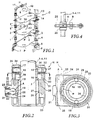
- Fig. 1
- eine schematische Perspektivansicht eines Teils eines Spulengestells mit Haltern für Spulendorne bzw. Spulen in vertikalen und/oder horizontalen Gestellstreben,
- Fig. 2
- einen Längsschnitt durch einen Halter, wie er in Fig. 1 verwendbar ist,
- Fig. 3
- einen Schnitt durch den Halter von Fig. 2 in der Ebene III-III, und
- Fig. 4
- eine schematische Seitenansicht
Claims (10)
- Spulendorn-Halter für ein Spulengestell (C), mit einem auf einer Gestellstrebe festlegbaren Hülsenkörper (15), auf dem außen eine konzentrische Ringfassung (19) drehbar gelagert und durch eine lösbare Federverrastung in wenigstens einer vorbestimmten Drehposition festlegbar ist, mit einem auf der Ringfassung angeordneten Lagerbock (20), in den eine Aufnahme für den Spulendorn eingeformt ist, und mit einer im Lagerbock in die Aufnahme mündenden Gewindebohrung für eine Fixierschraube (35), dadurch gekennzeichnet, daß im Lagerbock (20) eine die Aufnahme (A) bildende, beidendig offene, in Umfangsrichtung geschlossene Bohrung (24) mit quer zur Achsrichtung der Ringfassung (19) liegender Bohrungsachse (25) und einem zumindest teilweise die Ringfassung (19) durchsetzenden Mittellängsabschnitt (M) vorgesehen ist.
- Spulendorn-Halter nach Anspruch 1, dadurch gekennzeichnet, daß die Länge der Bohrung (24) annähernd dem Außendurchmesser der Ringfassung (19) entspricht, und daß die Gewindebohrung (23) von außen etwa radial auf die Ringfassungs-Achse gerichtet ist.
- Spulendorn-Halter nach Anspruch 2, dadurch gekennzeichnet, daß die Gewindebohrung (23) in einem Fortsatz (21) des Lagerbocks (20) angeordnet ist.
- Spulendorn-Halter nach den Ansprüchen 2 und 3, dadurch gekennzeichnet, daß in den Lagerbock (20) bzw. den Fortsatz (21) ein die Gewindebohrung (23) enthaltender Gewindeeinsatz (22) dreh- und ausziehfest eingebettet ist.
- Spulendorn-Halter nach Anspruch 1, dadurch gekennzeichnet, daß die Federverrastung (F) in zwei um ca. 180° zueinander verdrehten Drehpositionen der Ringfassung (19) einrastbar ist.
- Spulendorn-Halter nach den Ansprüchen 1 und 5, dadurch gekennzeichnet, daß der Hülsenkörper (15) in einem axial begrenzten Längsabschnitt zwei diametral gegenüberliegende, nach außen offene, in etwa V-förmige Rastvertiefungen (16) für je einen Wälzkörper (29) und die Rastvertiefungen (16) miteinander verbindende, in Umfangsrichtung verlaufende Wälzkörper-Auflagen (38) aufweist, daß die über die Rastvertiefungen (16) nach außen vorstehenden Wälzkörper (29) in Umfangsaussparungen (39) der sich bis über den Längsabschnitt des Hülsenkörpers (15) erstreckenden Ringfassung (19) eingreifen, daß auf den Wälzkörpern (29) außen eine C-förmige, sich in Umfangsrichtung erstreckende, vorgespannte Feder (30) aufliegt, und daß in der Ringfassung (19) innen ein radialer Federexpansionsbereich (31) ausgespart ist.
- Spulendorn-Halter nach wenigstens einem der Ansprüche 1 bis 6, dadurch gekennzeichnet, daß der Hülsenkörper (15) die Ringfassung (19) an beiden Enden axial überragt und kreisringförmige Kappen (32, 33) trägt, die, vorzugsweise, mit wenigstens einem Sicherungsbolzen (37) axial und in Drehrichtung fest mit dem Hülsenkörper (15) verbunden sind, und daß in zumindest einer Kappe (32, 33) eine radiale Gewindebohrung (34) für wenigstens eine durch eine mit der Gewindebohrung fluchtende Radialbohrung (17) des Hülsenkörpers (15) bis in die Innenbohrung des Hülsenkörpers (15) einschraubbare Fixierschraube (35) vorgesehen ist.
- Spulendorn-Halter nach wenigstens einem der Ansprüche 1 bis 7, dadurch gekennzeichnet, daß die Bohrung (24) und der Lagerbock (20) senkrecht zur Achsrichtung des Halters (H) liegen.
- Spulendorn-Halter nach wenigstens einem der Ansprüche 1 bis 8, dadurch gekennzeichnet, daß die Ringfassung (19) und der Hülsenkörper (15) je ein Formteil aus faserverstärktem Kunststoff sind.
- Spulendorn-Halter nach wenigstens einem der Ansprüche 1 bis 9, dadurch gekennzeichnet, daß die Kappen (32, 33) aus Metall, vorzugsweise Zinkdruckguß, bestehen.
Applications Claiming Priority (3)
| Application Number | Priority Date | Filing Date | Title |
|---|---|---|---|
| DE19537571A DE19537571A1 (de) | 1995-10-09 | 1995-10-09 | Spulendorn-Halter für ein Spulengestell |
| DE19537571 | 1995-10-09 | ||
| PCT/EP1996/004380 WO1997013715A1 (de) | 1995-10-09 | 1996-10-09 | Spulendorn-halter für ein spulengestell |
Publications (2)
| Publication Number | Publication Date |
|---|---|
| EP0854835A1 EP0854835A1 (de) | 1998-07-29 |
| EP0854835B1 true EP0854835B1 (de) | 2000-01-26 |
Family
ID=7774394
Family Applications (1)
| Application Number | Title | Priority Date | Filing Date |
|---|---|---|---|
| EP96934594A Expired - Lifetime EP0854835B1 (de) | 1995-10-09 | 1996-10-09 | Spulendorn-halter für ein spulengestell |
Country Status (7)
| Country | Link |
|---|---|
| US (1) | US5944272A (de) |
| EP (1) | EP0854835B1 (de) |
| KR (1) | KR100304181B1 (de) |
| CN (1) | CN1069879C (de) |
| AT (1) | ATE189178T1 (de) |
| DE (2) | DE19537571A1 (de) |
| WO (1) | WO1997013715A1 (de) |
Families Citing this family (6)
| Publication number | Priority date | Publication date | Assignee | Title |
|---|---|---|---|---|
| WO2009027885A2 (en) * | 2007-08-24 | 2009-03-05 | Steen Mandsfelt Eriksen | Assembling arrangement for securing a tubular furniture leg to the top plate of a piece of furniture |
| US20110127364A1 (en) * | 2009-12-01 | 2011-06-02 | Rees John J M | Mobile creel |
| KR101648516B1 (ko) * | 2009-12-18 | 2016-08-18 | 에스케이텔레콤 주식회사 | 제로크로싱복조를 이용한 보정용 fsk 수신기 및 이의 제어방법 |
| CN108330586B (zh) * | 2018-04-24 | 2023-12-29 | 青岛中利达纺织品有限公司 | 一种使用方便的纺织纱架 |
| BE1030231B1 (nl) | 2022-01-28 | 2023-08-29 | Vandewiele Nv | Bobijnrek voor een textielmachine |
| EP4499908A2 (de) * | 2022-03-24 | 2025-02-05 | Belmont Textile Machinery Company | Stromgetriebene spulengattersysteme, empfängervorrichtungen und zugehörige verfahren für garnspulen |
Family Cites Families (21)
| Publication number | Priority date | Publication date | Assignee | Title |
|---|---|---|---|---|
| US2704643A (en) * | 1955-03-22 | Lambach | ||
| CA516907A (en) * | 1955-09-27 | British Celanese Limited | Yarn-supply creels | |
| GB293439A (de) * | 1927-07-08 | 1929-05-27 | Universal Winding Company | |
| US1886638A (en) * | 1928-08-31 | 1932-11-08 | Universal Winding Co | Balloon-guard for creels or the like |
| US1962108A (en) * | 1930-09-16 | 1934-06-05 | Cocker Machine And Foundry Com | Creel |
| US2021032A (en) * | 1933-04-28 | 1935-11-12 | Universal Winding Co | Yarn controller for creels and like apparatus |
| US2844335A (en) * | 1955-05-25 | 1958-07-22 | Cocker Machine & Foundry Compa | Creel |
| US3391889A (en) * | 1966-06-07 | 1968-07-09 | Cocker Machine & Foundry Compa | Yarn package holder for textile creels |
| GB1351121A (en) * | 1970-02-13 | 1974-04-24 | Tmm Research Ltd | Creels for supporting textile bobbins |
| GB1413619A (en) * | 1973-03-05 | 1975-11-12 | Heberlein & Co Ag | Rotatable bobbin creels for stretch-texturing machines |
| CH631676A5 (de) * | 1978-09-15 | 1982-08-31 | Benninger Ag Maschf | Fadenfuehrung an einem spulengatter. |
| GB2113288B (en) * | 1981-11-25 | 1985-08-14 | I & C Carbonite Ltd | Stud and socket mechanism for releasably holding a rotatable member on a spindle |
| US4572458A (en) * | 1984-11-14 | 1986-02-25 | American Barmag Corporation | Compact creel for large diameter yarn supply packages |
| US4880184A (en) * | 1988-09-19 | 1989-11-14 | Crow Mitchell A | Yarn package support for creel |
| GB8926108D0 (en) * | 1989-11-18 | 1990-01-10 | Rieter Scragg Ltd | Textile apparatus |
| US5271684A (en) * | 1992-12-16 | 1993-12-21 | The Whitaker Corporation | Rotatably mounted cable for communication equipment |
| US5323982A (en) * | 1993-01-08 | 1994-06-28 | Ligon Lang S | Low profile yarn supply apparatus for a loom having pneumatic yarn threading |
| FR2708684A3 (fr) * | 1993-08-04 | 1995-02-10 | Shen Jack | Joint tournant pour appareil électrique. |
| US5522565A (en) * | 1994-04-12 | 1996-06-04 | Deshaies; Marcel R. | Adjustable yarn package holder |
| US5624082A (en) * | 1995-09-11 | 1997-04-29 | Ligon; Lang S. | In-line yarn feed creel |
| US5810271A (en) * | 1997-08-04 | 1998-09-22 | Rjs Corporation | Roller board and method for loading the same |
-
1995
- 1995-10-09 DE DE19537571A patent/DE19537571A1/de not_active Withdrawn
-
1996
- 1996-10-09 AT AT96934594T patent/ATE189178T1/de not_active IP Right Cessation
- 1996-10-09 US US09/051,065 patent/US5944272A/en not_active Expired - Fee Related
- 1996-10-09 CN CN96197529A patent/CN1069879C/zh not_active Expired - Fee Related
- 1996-10-09 EP EP96934594A patent/EP0854835B1/de not_active Expired - Lifetime
- 1996-10-09 WO PCT/EP1996/004380 patent/WO1997013715A1/de not_active Ceased
- 1996-10-09 DE DE59604326T patent/DE59604326D1/de not_active Expired - Fee Related
- 1996-10-09 KR KR1019980702591A patent/KR100304181B1/ko not_active Expired - Fee Related
Also Published As
| Publication number | Publication date |
|---|---|
| CN1069879C (zh) | 2001-08-22 |
| EP0854835A1 (de) | 1998-07-29 |
| US5944272A (en) | 1999-08-31 |
| KR19990064110A (ko) | 1999-07-26 |
| DE59604326D1 (de) | 2000-03-02 |
| DE19537571A1 (de) | 1997-05-07 |
| ATE189178T1 (de) | 2000-02-15 |
| WO1997013715A1 (de) | 1997-04-17 |
| CN1199379A (zh) | 1998-11-18 |
| KR100304181B1 (ko) | 2001-12-12 |
Similar Documents
| Publication | Publication Date | Title |
|---|---|---|
| DE4320480C2 (de) | Schnellspannvorrichtung zur Erzeugung von axialen Spannkräften auf einer glatten Welle | |
| EP0132458A2 (de) | Gasdruckfeder mit Sicherungsvorrichtung | |
| EP0854835B1 (de) | Spulendorn-halter für ein spulengestell | |
| DE2225555C3 (de) | Spulenhalter | |
| DE1659997A1 (de) | Wickeleinrichtung fuer Rolljalousien od.dgl. | |
| DE1435219B2 (de) | Klöppel für Flechtmaschinen, insbesondere Schlauchumflechtungsmaschinen | |
| EP1518810B1 (de) | Fadenbremse und damit ausgerütsete Textilmaschine und Fadenliefervorrichtung | |
| DE2151184C3 (de) | Kolben fur Kraft- oder Arbeitsmaschinen | |
| EP0091992B1 (de) | Befestigungsvorrichtung für das bandförmige Tragmittel eines Hebezeuges | |
| DE3927607A1 (de) | Spulvorrichtung | |
| DE3437160A1 (de) | Pneumatischer oder hydraulischer arbeitszylinder | |
| DE4005284A1 (de) | Anlenkung fuer die tuerhaltestange eines kraftfahrzeugtuerfeststellers | |
| DE7535360U (de) | Spulenaufhaengevorrichtung | |
| DE3201138C2 (de) | Verriegelungsvorrichtung zur axialen Festlegung von nicht drehbaren Spulen eines Drahtablaufgerätes mit horizontalen feststehenden Achsen | |
| DE7922045U1 (de) | Tragstange, die zwischen zwei einander gegenüberliegenden Stützpunkten einspannbar ist | |
| DE1560611A1 (de) | Verbesserungen an Tragvorrichtungen fuer Aufwickelspulen in Textilmaschinen | |
| DE2248724A1 (de) | Tuerband | |
| DE2000154A1 (de) | Reibungsdaempfer | |
| EP0768268B1 (de) | Spulengestell, Halter für eine Trennplatte in dem Spulengestell und Trennplatte | |
| DE365576C (de) | Abspulvorrichtung | |
| DE3728606A1 (de) | Bremszylinder fuer schienenfahrzeuge | |
| DE1087058B (de) | Traeger fuer haengende Ablaufspulen | |
| CH526070A (de) | Zusammenklappbarer Ständer | |
| DE1820758U (de) | Lagerrohr fuer spindeln von spinnereimaschinen. | |
| DE2431998A1 (de) | Zwirnrolle und deren herstellungsverfahren |
Legal Events
| Date | Code | Title | Description |
|---|---|---|---|
| PUAI | Public reference made under article 153(3) epc to a published international application that has entered the european phase |
Free format text: ORIGINAL CODE: 0009012 |
|
| 17P | Request for examination filed |
Effective date: 19980408 |
|
| AK | Designated contracting states |
Kind code of ref document: A1 Designated state(s): AT BE CH DE ES FR GB IT LI NL SE |
|
| GRAG | Despatch of communication of intention to grant |
Free format text: ORIGINAL CODE: EPIDOS AGRA |
|
| 17Q | First examination report despatched |
Effective date: 19981112 |
|
| GRAG | Despatch of communication of intention to grant |
Free format text: ORIGINAL CODE: EPIDOS AGRA |
|
| GRAH | Despatch of communication of intention to grant a patent |
Free format text: ORIGINAL CODE: EPIDOS IGRA |
|
| GRAH | Despatch of communication of intention to grant a patent |
Free format text: ORIGINAL CODE: EPIDOS IGRA |
|
| GRAA | (expected) grant |
Free format text: ORIGINAL CODE: 0009210 |
|
| AK | Designated contracting states |
Kind code of ref document: B1 Designated state(s): AT BE CH DE ES FR GB IT LI NL SE |
|
| PG25 | Lapsed in a contracting state [announced via postgrant information from national office to epo] |
Ref country code: SE Free format text: THE PATENT HAS BEEN ANNULLED BY A DECISION OF A NATIONAL AUTHORITY Effective date: 20000126 Ref country code: GB Free format text: LAPSE BECAUSE OF FAILURE TO SUBMIT A TRANSLATION OF THE DESCRIPTION OR TO PAY THE FEE WITHIN THE PRESCRIBED TIME-LIMIT Effective date: 20000126 Ref country code: ES Free format text: THE PATENT HAS BEEN ANNULLED BY A DECISION OF A NATIONAL AUTHORITY Effective date: 20000126 |
|
| REF | Corresponds to: |
Ref document number: 189178 Country of ref document: AT Date of ref document: 20000215 Kind code of ref document: T |
|
| REG | Reference to a national code |
Ref country code: CH Ref legal event code: EP |
|
| REF | Corresponds to: |
Ref document number: 59604326 Country of ref document: DE Date of ref document: 20000302 |
|
| ITF | It: translation for a ep patent filed | ||
| REG | Reference to a national code |
Ref country code: CH Ref legal event code: NV Representative=s name: BOVARD AG PATENTANWAELTE |
|
| ET | Fr: translation filed | ||
| GBV | Gb: ep patent (uk) treated as always having been void in accordance with gb section 77(7)/1977 [no translation filed] |
Effective date: 20000126 |
|
| PLBE | No opposition filed within time limit |
Free format text: ORIGINAL CODE: 0009261 |
|
| STAA | Information on the status of an ep patent application or granted ep patent |
Free format text: STATUS: NO OPPOSITION FILED WITHIN TIME LIMIT |
|
| 26N | No opposition filed | ||
| PGFP | Annual fee paid to national office [announced via postgrant information from national office to epo] |
Ref country code: FR Payment date: 20011018 Year of fee payment: 6 Ref country code: AT Payment date: 20011018 Year of fee payment: 6 |
|
| PGFP | Annual fee paid to national office [announced via postgrant information from national office to epo] |
Ref country code: NL Payment date: 20011026 Year of fee payment: 6 |
|
| PG25 | Lapsed in a contracting state [announced via postgrant information from national office to epo] |
Ref country code: AT Free format text: LAPSE BECAUSE OF NON-PAYMENT OF DUE FEES Effective date: 20021009 |
|
| PG25 | Lapsed in a contracting state [announced via postgrant information from national office to epo] |
Ref country code: NL Free format text: LAPSE BECAUSE OF NON-PAYMENT OF DUE FEES Effective date: 20030501 |
|
| PG25 | Lapsed in a contracting state [announced via postgrant information from national office to epo] |
Ref country code: FR Free format text: LAPSE BECAUSE OF NON-PAYMENT OF DUE FEES Effective date: 20030630 |
|
| NLV4 | Nl: lapsed or anulled due to non-payment of the annual fee |
Effective date: 20030501 |
|
| REG | Reference to a national code |
Ref country code: FR Ref legal event code: ST |
|
| PGFP | Annual fee paid to national office [announced via postgrant information from national office to epo] |
Ref country code: CH Payment date: 20051024 Year of fee payment: 10 Ref country code: BE Payment date: 20051024 Year of fee payment: 10 |
|
| PGFP | Annual fee paid to national office [announced via postgrant information from national office to epo] |
Ref country code: DE Payment date: 20051129 Year of fee payment: 10 |
|
| PG25 | Lapsed in a contracting state [announced via postgrant information from national office to epo] |
Ref country code: LI Free format text: LAPSE BECAUSE OF NON-PAYMENT OF DUE FEES Effective date: 20061031 Ref country code: CH Free format text: LAPSE BECAUSE OF NON-PAYMENT OF DUE FEES Effective date: 20061031 |
|
| PG25 | Lapsed in a contracting state [announced via postgrant information from national office to epo] |
Ref country code: DE Free format text: LAPSE BECAUSE OF NON-PAYMENT OF DUE FEES Effective date: 20070501 |
|
| REG | Reference to a national code |
Ref country code: CH Ref legal event code: PL |
|
| BERE | Be: lapsed |
Owner name: *IRO A.B. Effective date: 20061031 |
|
| PGFP | Annual fee paid to national office [announced via postgrant information from national office to epo] |
Ref country code: IT Payment date: 20081022 Year of fee payment: 13 |
|
| PG25 | Lapsed in a contracting state [announced via postgrant information from national office to epo] |
Ref country code: BE Free format text: LAPSE BECAUSE OF FAILURE TO SUBMIT A TRANSLATION OF THE DESCRIPTION OR TO PAY THE FEE WITHIN THE PRESCRIBED TIME-LIMIT Effective date: 20061031 |
|
| PG25 | Lapsed in a contracting state [announced via postgrant information from national office to epo] |
Ref country code: IT Free format text: LAPSE BECAUSE OF NON-PAYMENT OF DUE FEES Effective date: 20091009 |