EP0854835B1 - Coil core holder for a coil frame - Google Patents
Coil core holder for a coil frame Download PDFInfo
- Publication number
- EP0854835B1 EP0854835B1 EP96934594A EP96934594A EP0854835B1 EP 0854835 B1 EP0854835 B1 EP 0854835B1 EP 96934594 A EP96934594 A EP 96934594A EP 96934594 A EP96934594 A EP 96934594A EP 0854835 B1 EP0854835 B1 EP 0854835B1
- Authority
- EP
- European Patent Office
- Prior art keywords
- bore
- ring socket
- bobbin core
- sleeve body
- core holder
- Prior art date
- Legal status (The legal status is an assumption and is not a legal conclusion. Google has not performed a legal analysis and makes no representation as to the accuracy of the status listed.)
- Expired - Lifetime
Links
Images
Classifications
-
- D—TEXTILES; PAPER
- D02—YARNS; MECHANICAL FINISHING OF YARNS OR ROPES; WARPING OR BEAMING
- D02H—WARPING, BEAMING OR LEASING
- D02H1/00—Creels, i.e. apparatus for supplying a multiplicity of individual threads
-
- B—PERFORMING OPERATIONS; TRANSPORTING
- B65—CONVEYING; PACKING; STORING; HANDLING THIN OR FILAMENTARY MATERIAL
- B65H—HANDLING THIN OR FILAMENTARY MATERIAL, e.g. SHEETS, WEBS, CABLES
- B65H49/00—Unwinding or paying-out filamentary material; Supporting, storing or transporting packages from which filamentary material is to be withdrawn or paid-out
- B65H49/02—Methods or apparatus in which packages do not rotate
- B65H49/04—Package-supporting devices
- B65H49/14—Package-supporting devices for several operative packages
- B65H49/16—Stands or frameworks
-
- B—PERFORMING OPERATIONS; TRANSPORTING
- B65—CONVEYING; PACKING; STORING; HANDLING THIN OR FILAMENTARY MATERIAL
- B65H—HANDLING THIN OR FILAMENTARY MATERIAL, e.g. SHEETS, WEBS, CABLES
- B65H2701/00—Handled material; Storage means
- B65H2701/30—Handled filamentary material
- B65H2701/31—Textiles threads or artificial strands of filaments
Definitions
- the invention relates to a mandrel holder in the preamble of the known type of claim 1, see US-A-3 391 889.
- Electrotex for vertical frame struts (p. I3, p. I5) is the bearing block not arranged radially on the outer circumference of the ring frame.
- the receptacle is a blind bore with approximately the axis of the holder radial bore axis.
- One roughly tangent to the circumference the ring socket can be screwed into a threaded hole is used to define the inserted in the recording Spool.
- the pedestal protrudes from the known one Bracket wide. There is only a short support length for the spool. Furthermore, the Do not insert the mandrel far enough into the holder to to optimally hold a spool.
- the ring holder can be changed relative to the spool Set the sleeve body aside against the retaining action of the spring catch swing.
- the holder allows only one Position for the mandrel, which is determined by the position of the Holder is fixed to the frame strut.
- a mandrel holder known for horizontal frame struts at which the recording in a laterally protruding from the ring setting Bearing bracket and open at both ends, so that the mandrel from one side or the other has the receptacle plugged in.
- the ring setting is fixed Holder from the one held by the weight of the spool Working position easily rotatable in one direction (Spool change). To the mandrel on the other side of the To be able to hold the frame strut, it is necessary to Loosen the holder on the frame strut and twist it altogether.
- the invention has for its object a mandrel holder of the type mentioned at the beginning, which is suitable for horizontal and vertical frame struts are equally suitable, the swivel away of the spool to swap the spool without Loosening of fasteners allows compact dimensions has and a stable and space-saving support of the Allow spool mandrel.
- the holder should enable a spool without any complex manipulation either position one or the other side of the frame strut to be able to make confined spaces easier To take into account or an optimal thread outlet geometry allow.
- the holder is compact, easy to use and enables a particularly stable and space-saving support for the spool on each frame strut.
- the bore uses namely the space in the flesh of the ring setting and is therefore convenient close to the frame strut.
- the bearing block protrudes only a little outward.
- the spool is supported close to the frame strut.
- the holder can be used for both vertical and use for horizontal frame struts
- the short lever arm the long hole opposite the axis of the ring setting saves not only space, but leads to a stable support the mass of the coil during or against vibrations.
- the bore according to claim 2 is extremely long, it with their end sections leaving the ring frame in the bearing block runs, there is a very large support length for the Coil mandrel available.
- the open bore at both ends leaves it, the coil mandrel, or actually the foot part of the coil mandrel, insert as far as this for optimal and stable support of the coil is appropriate.
- the free end of the spool is even out of the hole in front.
- the spool can be inserted from either end of the hole be so that the ring setting - if there is space or require the thread geometry - rotated by 180 ° can be to the mandrel on the other side of the Support the brace.
- the fixing screw is convenient manageable, since it is placed in an optimally accessible place.
- the rotatability the ring setting and the spring catch have one Double function because it is easy to use allow when changing bobbins because only the ring holder to be rotated accordingly far from the working position needs, and on the other hand the ring setting also rotated by 180 ° can be to the mandrel on the other side of the Position frame braces.
- the embodiment according to claim 3 is advantageous because the extension of the pedestal has enough meat for the fixing screw ensures in the threaded hole without the compact Significantly increase the dimensions of the holder.
- the embodiment according to claim is particularly expedient 4 because the thread does not wear out even after a long service life is to be feared.
- the embodiment according to claim 5 has the advantage that the Ring setting two diametrically opposite fixed turning positions in which the spool can be supported. It leaves the spool, if there is space or the thread geometry require from one side of the frame strut move the other side without having to loosen the bracket.
- a manufacturing technology and assembly technology favorable embodiment emerges from claim 6.
- the spring catch can be easily within the compact dimensions of the Place the ring frame and the sleeve body. With the C-shaped Spring hold high holding forces for stable turning positions the ring setting is reached as soon as the rolling elements in the Intervene with recesses.
- a particularly stable fixation of the holder on the frame strut is possible in the embodiment according to claim 7. Furthermore, the caps and the fixation of the caps and the Sleeve body on the frame struts manufacturing and assembly technology expedient.
- the embodiment according to claim 8 is used to define a Spool mandrel perpendicular to the axis of the frame strut.
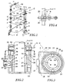
- a bobbin frame C according to FIG. 1 as is the case, for example looms equipped with thread delivery devices to support the possibly voluminous and heavy thread spools, has, for example, four vertical frame struts 1, 2, 3, 4, which have a base 5 with a base 6 and impellers 7 are connected to each other.
- vertical Frame struts 1, 2, 3, 4 which have a base 5 with a base 6 and impellers 7 are connected to each other.
- frame struts such as the frame strut 11, which act stiffening and also the bracket of coils.
- the coil frame C can be divided into several Floors are divided, namely by means of partition plates P, the removable on the plate brackets of the frame struts 8 are attached. It is usually a coil frame (Fig. 1 lower part) only with vertical frame struts, from which all coils are held, and with superimposed ones Tiers, or around a bobbin rack only with horizontal Frame struts (as in Fig. 1 above) for support of the coils, and adjacent compartments, separately by hanging partition plates.
- Each for supporting the Coil-provided rack struts are of course with other Frame struts connected to a self-supporting structure, the other frame struts are not for support be used by coils. But also the one shown in Fig. 1 Mixed form with horizontal and vertical frame struts define the frame and serve to support coils is workable.
- the coil 10 indicated in the middle in FIG. 1 shows that the holder is set so that the axis of the Spool 10 or its spool mandrel approximately to the associated drain eyelet points.
- the holder H has (Fig. 2 and 3) a ring setting (Fig. 2), which can be rotated by 180 ° to the Position the mandrel 9 'on the other side of the frame strut 1, e.g. for space reasons and / or because of the thread drain geometry.
- the mandrel 9 with the Ring holder in the direction of a double arrow 12 for a coil change Swing back and forth as far as you want. After one The new bobbin with the bobbin mandrel will change the bobbin again pivoted back into the respective working position and by the Holder fixed.
- the holder H has an inner sleeve body 15 on the frame strut 1 to 4, 11, e.g. is fixed with a fixing screw 35.
- a fixing screw 35 In an axial limited longitudinal area of the bobbin 15 are two on the outside diametrically opposed locking recesses 16 are formed.
- At least one end of the sleeve body 15 contains a radial one Hole 17 (a threaded hole if necessary) for the fixing screw 35.
- a receptacle 18 is formed in the offset point.
- a concentric ring mount is rotatable on the sleeve body 15 19 arranged a transverse to the axis of the ring frame 19 extending, integrally molded bearing block 20 bears an extension projecting approximately in the middle 21 owns.
- a Threaded insert 22 embedded, which is a threaded bore 23 for has a fixing screw, not shown.
- the threaded hole 23 opens into a receptacle A for a not shown Spool mandrel 9.
- the receptacle A is one in the circumferential direction closed, open at both ends longitudinal bore 24 in the bearing block 20, the bore 24 being a circular segment in FIG. 3 Has central longitudinal section M, which is within the ring frame 19 lies.
- the bore axis 25 is therefore located close to the sleeve body 15 or the frame strut.
- the bore axis 25 runs vertically with the bearing block 20 to the axis of the frame strut, as indicated in FIG. 4 is.
- the sleeve body 15 has a circumferential shoulder 26 which cooperates with an inner shoulder 27 of the ring holder 19, to secure them axially.
- the ring frame 19 is in Fig. 2 threaded onto the sleeve body 15 from above.
- the ring holder 19 is inside with pocket-shaped cavities and stiffening ribs so that there is an inner Apron 28 results in that over the area of the recesses 16 in the sleeve body 15 is sufficient.
- two rolling elements 29 are mounted (e.g. barrel-shaped or are spherical). Each rolling element 29 is pending the recess 16 in front and engages in a circumferential recess 39 of the apron 28. Outside lies on the Rolling elements 29 have a C-shaped spring 30 with pretension, which holds the rolling elements 29 in the locking recesses 16.
- a radial Expansion space 31 is provided, the radial width so dimensioned is that the spring 30 can yield when the rolling elements 29 want to emerge from the recesses 16.
- annular caps 32, 33 are attached, either only plugged in or by means of securing bolts 37 secured against twisting and peeling.
- the cap 32 is one Radial bore 36 can be seen in which the securing bolt 37 so widely used and, e.g. by gluing, it is ensured that it enters the receptacle 18 with its inner end.
- a threaded bore 34 is in the cap 32 for the fixing screw 35 is provided, which is against the circumference the frame strut 1 to 4, 11 can tension and thus the position of the sleeve body 15 on the frame strut.
- Pads 38 shaped for the rolling elements 29 are on the sleeve body 15 Pads 38 shaped for the rolling elements 29.
- Rolling bodies 29 is the ring socket 19 in a certain Set rotational position on the sleeve body 15.
- the Spool mandrel 9 is inserted into the bore 24 as far as this is necessary for the optimal positioning of the coil is held, and by means of a in the threaded bore 23 screwed fixing screw.
- the ring socket 19 by means of the coil mandrel rotated relative to the sleeve body 15. In doing so, the inclined ramps that delimit the recesses 16 that Rolling elements 29 are lifted out of the locking recesses 16 and through the circumferential recesses 39 in the apron 28 of the ring frame 19 moved along the supports 38 in the direction of rotation.
- the spring 30 expands into the expansion space 31. Die Friction of the rolling elements 29 under the force of the spring 30 is sufficient off, the twisted ring socket 19 when changing the spool position. If a new bobbin is attached, use the the ring mandrel back into the original Turned back position until the rolling elements 29 in the Engaging recesses 16. Shall the mandrel go to the other Side of the frame strut, then the Ring setting rotated by 180 ° until the rolling elements 29 in again the recesses come in. The mandrel 9 is then from the other end of the hole 24 inserted into it and fixed.
Landscapes
- Engineering & Computer Science (AREA)
- Textile Engineering (AREA)
- Winding Filamentary Materials (AREA)
- Storage Of Web-Like Or Filamentary Materials (AREA)
- Automatic Tape Cassette Changers (AREA)
- Unwinding Webs (AREA)
- Warping, Beaming, Or Leasing (AREA)
Abstract
Description
Die Erfindung betrifft einen Spulendorn-Halter der im Oberbegriff des Patentanspruchs 1 bekannten Art, siehe US-A-3 391 889.The invention relates to a mandrel holder in the preamble of the known type of claim 1, see US-A-3 391 889.
Bei einem aus einem allgemeinen Katalog "Gestelle und Spulenhalter" der Fa. ROJ Electrotex bekannten Spulendorn-Halter für vertikale Gestellstreben (S. I3, S. I5), ist der Lagerbock nicht radial am Außenumfang der Ringfassung angeordnet. Die Aufnahme ist eine Sackbohrung mit in etwa zur Halterachse radialer Bohrungsachse. Eine in etwa tangential zum Umfang der Ringfassung in eine Gewindebohrung einschraubbares Fixierschraube dient zum Festlegen des in die Aufnahme eingesteckten Spulendorns. Der Lagerbock kragt bei dem bekannten Halter weit aus. Es ergibt sich eine nur kurze Stützlänge für den Spulendorn. Ferner läßt sich in manchen Fällen der Spulendorn nicht weit genug in die Aufnahme einschieben, um eine Spule optimal zu haltern. Es ergeben sich bei schweren Spulen lokale Belastungen, die zu einem frühzeitigen Verschleiß der Aufnahme, zu hohen Spannungen im Übergang vom Lagerbock zur Ringfassung und zu vibrierender Spule führen können. Zum Spulenwechsel läßt sich die Ringfassung relativ zum Hülsenkörper gegen die Haltewirkung der Federverrastung beiseite schwenken. Der Halter ermöglicht jedoch nur eine einzige Position für den Spulendorn, die durch die Position des Halters an der Gestellstrebe festgelegt ist.For one from a general catalog "Racks and spool holders" known from the company ROJ Electrotex for vertical frame struts (p. I3, p. I5) is the bearing block not arranged radially on the outer circumference of the ring frame. The receptacle is a blind bore with approximately the axis of the holder radial bore axis. One roughly tangent to the circumference the ring socket can be screwed into a threaded hole is used to define the inserted in the recording Spool. The pedestal protrudes from the known one Bracket wide. There is only a short support length for the spool. Furthermore, the Do not insert the mandrel far enough into the holder to to optimally hold a spool. It results in severe Coils local loads that cause premature wear the intake, too high tensions in the transition from the bearing block lead to the ring holder and vibrating coil. The ring holder can be changed relative to the spool Set the sleeve body aside against the retaining action of the spring catch swing. However, the holder allows only one Position for the mandrel, which is determined by the position of the Holder is fixed to the frame strut.
Es ist zwar aus demselben Katalog, S. I2 und S. I5 ein Spulendorn-Halter für horizontale Gestellstreben bekannt, bei dem die Aufnahme in einem seitlich von der Ringfassung abstehenden Lagerbock und beidendig offen ausgebildet ist, so daß sich der Spulendorn von der einen oder der anderen Seite in die Aufnahme einstecken läßt. Die Ringfassung ist bei festgelegtem Halter aus der durch das Gewicht der Spule gehaltener Arbeitsstellung in einer Richtung leicht verdrehbar (Spulenwechsel). Um den Spulendorn an der anderen Seite der Gestellstrebe haltern zu können, ist es erforderlich, den Halter auf der Gestellstrebe zu lösen und insgesamt zu verdrehen. Ungünstig ist ferner, daß der Spulendorn mit zwei Klemmschrauben zwischen zwei Klemmflanschen gehalten wird. Dies erfordert mühselige und zeitaufwendige Manipulationen zum Festlegen und Lösen des Spulendorns und die Lebensdauer beeinträchtigende Verformungen der Klemmflansche. Schließlich ist der Seitenabstand des Spulendorns von der Gestellstrebe verhältnismäßig groß, so daß bei schweren Spulen große Belastungen und exzentrische Kräfte auftreten, die die Halterung des Halters auf der Gestellstrebe beeinträchtigen und das Material des Halters ermüden. Der verhältnismäßig große Abstand des Spulendorns von der Achse der Gestellstrebe begünstigt ferner ein Vibrieren der angeordneten Spule.Although it is from the same catalog, p. I2 and p. I5, a mandrel holder known for horizontal frame struts, at which the recording in a laterally protruding from the ring setting Bearing bracket and open at both ends, so that the mandrel from one side or the other has the receptacle plugged in. The ring setting is fixed Holder from the one held by the weight of the spool Working position easily rotatable in one direction (Spool change). To the mandrel on the other side of the To be able to hold the frame strut, it is necessary to Loosen the holder on the frame strut and twist it altogether. It is also unfavorable that the mandrel with two Clamping screws are held between two clamping flanges. This requires laborious and time-consuming manipulations for setting and releasing the spool and the service life impairing deformations of the clamping flanges. Finally is the side distance of the spool from the frame strut relatively large, so that heavy loads on heavy coils and eccentric forces occur that hold the bracket of the holder on the frame strut and affect the material tired of the holder. The relatively large distance of the coil mandrel favored by the axis of the frame strut a vibration of the arranged coil.
Der Erfindung liegt die Aufgabe zugrunde, einen Spulendorn-halter der eingangs genannten Art zuschaffen, der sich für horizontale und vertikale Gestellstreben gleichermaßen eignet, das rasche Wegschwenken der Spule zum Spulentausch ohne Lösen von Befestigungsmitteln erlaubt, kompakte Abmessungen besitzt und eine stabile und platzsparende Abstützung des Spulendorns ermöglichen. Der Halter soll es ermöglichen soll, einen Spulendorn ohne aufwendige Manipulationen entweder an der einen oder an der anderen Seite der Gestellstrebe positionieren zu können, um beengten Platzverhältnissen leichter Rechnung zu tragen bzw. eine optimale Fadenablaufgeometrie zuzulassen.The invention has for its object a mandrel holder of the type mentioned at the beginning, which is suitable for horizontal and vertical frame struts are equally suitable, the swivel away of the spool to swap the spool without Loosening of fasteners allows compact dimensions has and a stable and space-saving support of the Allow spool mandrel. The holder should enable a spool without any complex manipulation either position one or the other side of the frame strut to be able to make confined spaces easier To take into account or an optimal thread outlet geometry allow.
Die gestellte Aufgabe wird mit den Merkmalen des Patentanspruchs 1 gelöst.The task is with the features of the claim 1 solved.
Der Halter ist kompakt, bedienungsfreundlich und ermöglicht eine besonders stabile und platzsparende Abstützung des Spulendorns an jeder Gestellstrebe. Die Bohrung nutzt nämlich den Raum im Fleisch der Ringfassung und liegt demzufolge günstig nahe an der Gestellstrebe. Der Lagerbock ragt nur wenig nach außen. Der Spulendorn wird nahe an der Gestellstrebe abgestützt. Der Halter läßt sich sowohl für vertikale als auch für horizontale Gestellstreben benutzen Der kurze Hebelarm der langen Bohrung gegenüber der Achse der Ringfassung spart nicht nur Platz, sondern führt zu einer stabilen Abstützung der Masse der Spule bei oder gegen Erschütterungen.The holder is compact, easy to use and enables a particularly stable and space-saving support for the spool on each frame strut. The bore uses namely the space in the flesh of the ring setting and is therefore convenient close to the frame strut. The bearing block protrudes only a little outward. The spool is supported close to the frame strut. The holder can be used for both vertical and use for horizontal frame struts The short lever arm the long hole opposite the axis of the ring setting saves not only space, but leads to a stable support the mass of the coil during or against vibrations.
Da die Bohrung gemäß Anspruch 2 extrem lang ist, wobei sie
mit ihren die Ringfassung verlassenden Endabschnitten im Lagerbock
verläuft, steht eine sehr große Stützlänge für den
Spulendorn zur Verfügung. Die beidendig offene Bohrung läßt
es zu, den Spulendorn, bzw. eigentlich den Fußteil des Spulendorns,
so weit einzuschieben, wie dies für eine optimale
und stabile Halterung der Spule zweckmäßig ist. Gegebenenfalls
steht das freie Ende des Spulendorns sogar aus der Bohrung
vor. Der Spulendorn kann von jedem Ende der Bohrung eingeführt
werden, so daß die Ringfassung - falls es die Platzverhältnisse
oder die Fadengeometrie erfordern - um 180° verdreht
werden kann, um den Spulendorn an der anderen Seite der
Gestellstrebe abzustützen. Die Fixierschraube ist bequem
handhabbar, da sie optimal zugänglich plaziert ist. Die Verdrehbarkeit
der Ringfassung und die Federverrastung haben eine
Doppelfunktion, da sie einerseits eine bequeme Handhabung
bei einem Spulentausch ermöglichen, weil nur die Ringfassung
entsprechend weit aus der Arbeitsposition verdreht zu werden
braucht, und andererseits die Ringfassung auch um 180° gedreht
werden kann, um den Spulendorn an der anderen Seite der
Gestellstreben zu positionieren.Since the bore according to
Die Ausführungsform gemäß Anspruch 3 ist vorteilhaft, weil
der Fortsatz des Lagerbocks genügend Fleisch für die Fixierschraube
in der Gewindebohrung sicherstellt, ohne die kompakten
Abmessungen des Halters nennenswert zu vergrößern. The embodiment according to
Besonders zweckmäßig ist die Ausführungsform gemäß Anspruch 4, weil auch nach langer Standzeit kein Ausleiern des Gewindes zu befürchten ist.The embodiment according to claim is particularly expedient 4 because the thread does not wear out even after a long service life is to be feared.
Die Ausführungsform gemäß Anspruch 5 hat den Vorteil, daß die
Ringfassung zwei diametral gegenüberliegende feste Drehpositionen
hat, in denen der Spulendorn abstützbar ist. Es läßt
sich somit der Spulendorn, falls es der Platz oder die Fadengeometrie
erfordern, von einer Seite der Gestellstrebe auf
die andere Seite umsetzen ohne die Halterung lösen zu müssen.The embodiment according to
Eine herstellungstechnisch und montagetechnisch günstige Ausführungsform
geht aus Anspruch 6 hervor. Die Federverrastung
läßt sich problemlos innerhalb der kompakten Abmessungen der
Ringfassung und des Hülsenkörpers unterbringen. Mit der C-förmigen
Feder weden hohe Haltekräfte für stabile Drehpositionen
der Ringfassung erreicht, sobald die Wälzkörper in die
Rastvertiefungen eingreifen.A manufacturing technology and assembly technology favorable embodiment
emerges from
Eine besonders stabile Fixierung des Halters auf der Gestellstrebe
ist bei der Ausführungsform gemäß Anspruch 7 möglich.
Ferner sind die Kappen und die Fixierung der Kappen und des
Hülsenkörpers an der Gestellstreben herstellungs- und montagetechnisch
zweckmäßig.A particularly stable fixation of the holder on the frame strut
is possible in the embodiment according to
Die Ausführungsform gemäß Anspruch 8 dient zum Festlegen eines
Spulendorns senkrecht zur Achse der Gestellstrebe.The embodiment according to
Herstellungstechnisch und in bezug auf die Lebensdauer und
das Gewicht sind die Ausführungsformen der Ansprüche 9 und 10
vorteilhaft.Technically and in terms of service life and
the weight are the embodiments of
Anhand der Zeichnungen werden Ausführungsformen des Erfindungsgegenstandes erläutert. Es zeigen:
- Fig. 1
- eine schematische Perspektivansicht eines Teils eines Spulengestells mit Haltern für Spulendorne bzw. Spulen in vertikalen und/oder horizontalen Gestellstreben,
- Fig. 2
- einen Längsschnitt durch einen Halter, wie er in Fig. 1 verwendbar ist,
- Fig. 3
- einen Schnitt durch den Halter von Fig. 2 in der Ebene III-III, und
- Fig. 4
- eine schematische Seitenansicht
- Fig. 1
- 2 shows a schematic perspective view of part of a coil frame with holders for coil mandrels or coils in vertical and / or horizontal frame struts,
- Fig. 2
- 2 shows a longitudinal section through a holder, as can be used in FIG. 1,
- Fig. 3
- a section through the holder of Fig. 2 in the plane III-III, and
- Fig. 4
- a schematic side view
Ein Spulengestell C gemäß Fig. 1, wie es beispielsweise an
mit Fadenliefergeräten ausgestatteten Webmaschinen benutzt
wird, um die ggfs. voluminösen und schweren Fadenspulen abzustützen,
weist beispielsweise vier vertikale Gestellstreben
1, 2, 3, 4 auf, die über einen Fußteil 5 mit einem Standfuß 6
und Laufrädern 7 miteinander verbunden sind. Sind nur vertikale
Gestellstreben vorgesehen, dann ist zweckmäßigerweise
auch ein nicht gezeigtes Kopfteil vorhanden, um das Gestell
stabil auszusteifen. Es ist aber auch denkbar, horizontale
Gestellstreben vorzusehen, beispielsweise wie die Gestellstrebe
11, die aussteifend wirken und ebenfalls die Halterung
von Spulen ermöglichen. Das Spulengestell C kann in mehrere
Etagen unterteilt werden, und zwar mittels Trennplatten P,
die an Trennplatten-Haltern der Gestellstreben 8 abnehmbar
angebracht sind. Üblicherweise handelt es sich um ein Spulengestell
(Fig. 1 unterer Teil) nur mit vertikalen Gestellstreben,
aus denen alle Spulen gehaltert werden, und mit übereinanderliegenden
Etagen, oder um ein Spulengestell nur mit horizontalen
Gestellstreben (wie in Fig. 1 oben) zum Abstützen
der Spulen, und nebeneinanderliegenden Fächern, getrennt
durch hängende Trennplatten. Die jeweils zum Abstützen der
Spulen vorgesehenen Gestellstreben sind natürlich mit weiteren
Gestellstreben zu einem selbsttragenden Gebilde verbunden,
wobei die weiteren Gestellstreben nicht zum Abstützen
von Spulen genutzt werden. Aber auch die in Fig. 1 gezeigte
Mischform mit horizontalen und vertikalen Gestellstreben, die
das Gestell definieren und zum Abstützen von Spulen dienen
ist praktikabel.A bobbin frame C according to FIG. 1, as is the case, for example
looms equipped with thread delivery devices
to support the possibly voluminous and heavy thread spools,
has, for example, four vertical frame struts
1, 2, 3, 4, which have a
Zum Haltern der Spulen 10 mit ihren Spulendornen 9 sind an
den Gestellstreben Spulendorn-Halter H angebracht, die im Detail
aus den Fig. 2 und 3 zu entnehmen sind. Die beiden Gestellstreben
3 und 4 sind über Einsätze 13 miteinander verbunden,
in denen Ablaufösen 14 für den jeweiligen Faden angeordnet
sind.To hold the
Bei der in Fig. 1 in der Mitte angedeuteten Spule 10 ist erkennbar,
daß der Halter so festgelegt ist, daß die Achse der
Spule 10 bzw. deren Spulendorns in etwa zur zugehörigen Ablauföse
weist. Der Halter H weist (Fig. 2 und 3) eine Ringfassung
(Fig. 2) auf, die sich um 180° verdrehen läßt, um den
Spulendorn 9' an der anderen Seite der Gestellstrebe 1 zu positionieren,
z.B. aus Platzgründen und/oder wegen der Fadenablaufgeometrie.
Ferner läßt sich der Spulendorn 9 mit der
Ringfassung in Richtung eines Doppelpfeiles 12 zu einem Spulenwechsel
beliebig weit hin- und herschwenken. Nach einem
Spulenwechsel wird die neue Spule mit dem Spulendorn wieder
in die jeweilige Arbeitslage zurückgeschwenkt und durch den
Halter fixiert.The
Gemäß den Fig. 2 und 3 weist der Halter H einen inneren Hülsenkörper
15 auf, der an der Gestellstrebe 1 bis 4, 11, z.B.
mit einer Fixierschraube 35, festgelegt ist. In einem axial
begrenzten Längsbereich des Spulenkörpers 15 sind außen zwei
diametral gegenüberliegende Rastvertiefungen 16 eingeformt.
Zumindest ein Ende des Hülsenkörpers 15 enthält eine radiale
Bohrung 17 (gegebenenfalls eine Gewindebohrung) für die Fixierschraube
35. An einer zur Bohrung 17 in Umfangsrichtung
versetzten Stelle ist eine Aufnahme 18 eingeformt. 2 and 3, the holder H has an
Auf dem Hülsenkörper 15 ist drehbar eine konzentrische Ringfassung
19 angeordnet, die einen quer zur Achse der Ringfassung
19 verlaufenden, einstückig angeformten Lagerbock 20
trägt, der in etwa mittig einen nach außen ragenden Fortsatz
21 besitzt. In den Fortsatz 21 und den Lagerbock 20 ist ein
Gewindeeinsatz 22 eingebettet, der eine Gewindebohrung 23 für
eine nicht dargestellte Fixierschraube aufweist. Die Gewindebohrung
23 mündet in eine Aufnahme A für einen nicht gezeigten
Spulendorn 9. Die Aufnahme A ist eine in Umfangsrichtung
geschlossene, beidendig offene Längsbohrung 24 im Lagerbock
20, wobei die Bohrung 24 einen in Fig. 3 kreisabschnittförmigen
Mittellängsabschnitt M besitzt, der innerhalb der Ringfassung
19 liegt. Die Bohrungsachse 25 befindet sich demzufolge
nahe an dem Hülsenkörper 15 bzw. der Gestellstrebe.A concentric ring mount is rotatable on the
Die Bohrungsachse 25 verläuft mit dem Lagerbock 20 senkrecht
zur Achse der Gestellstrebe, so wie dies in der Fig. 4 angedeutet
ist.The
Der Hülsenkörper 15 weist eine Umfangsschulter 26 auf, die
mit einer inneren Schulter 27 der Ringfassung 19 zusammenarbeitet,
um diese axial zu sichern. Die Ringfassung 19 wird in
Fig. 2 von oben auf den Hülsenkörper 15 aufgefädelt.The
Die Ringfassung 19 ist innen mit taschenförmigen Hohlräumen
und Versteifungsrippen ausgestattet, so daß sich eine innere
Schürze 28 ergibt, die bis über den Bereich der Rastvertiefungen
16 im Hülsenkörper 15 reicht. In den Rastvertiefungen
16 sind (in der Haltestellung bzw. der fixierten Drehposition
der Ringfassung 19) zwei Wälzkörper 29 gelagert (z.B. tonnenförmig
oder kugelförmig sind). Jeder Wälzkörper 29 steht aus
der Rastvertiefung 16 nach außen vor und greift in eine Umfangsausnehmung
39 der Schürze 28 ein. Außen liegt auf den
Wälzkörpern 29 eine C-förmige Feder 30 mit Vorspannung auf,
die die Wälzkörper 29 in den Rastvertiefungen 16 festhält. The
Außerhalb der Feder 30 ist in der Ringfassung 19 ein radialer
Expansionsraum 31 vorgesehen, dessen radiale Weite so bemessen
ist, daß die Feder 30 nachgeben kann, wenn die Wälzkörper
29 aus den Rastvertiefungen 16 austreten wollen.Outside the
An beiden Enden des die Ringfassung 19 überragenden Hülsenkörpers
15 sind kreisringförmige Kappen 32, 33 angebracht,
entweder nur aufgesteckt oder mittels Sicherungsbolzen 37
verdreh- und abziehfest gesichert. In der Kappe 32 ist eine
Radialbohrung 36 erkennbar, in die der Sicherungsbolzen 37 so
weit eingesetzt und, z.B. durch Verkleben, gesichert ist, daß
er mit seinem innenliegenden Ende bis in die Aufnahme 18 eintritt.
Ferner ist in der Kappe 32 eine Gewindebohrung 34 für
die Fixierschraube 35 vorgesehen, die sich gegen den Umfang
der Gestellstrebe 1 bis 4, 11 spannen läßt und damit die Position
des Hülsenkörpers 15 an der Gestellstrebe festlegt.
Zwischen den Rastvertiefungen 16 sind auf dem Hülsenkörper 15
Auflagen 38 für die Wälzkörper 29 geformt.At both ends of the sleeve body projecting beyond the
Bei gemäß Fig. 2 und 3 in die Rastvertiefungen 16 hineingedrückten
Wälzkörpern 29 ist die Ringfassung 19 in einer bestimmten
Drehposition auf dem Hülsenkörper 15 festgelegt. Der
Spulendorn 9 ist in die Bohrung 24 so weit eingeschoben, wie
dies für die optimale Positionierung der Spule für erforderlich
gehalten wird, und mittels einer in die Gewindebohrung
23 eingeschraubten Fixierschraube festgelegt. Zu einem Spulenwechsel
wird mittels des Spulendorns die Ringfassung 19
relativ zum Hülsenkörper 15 verdreht. Dabei werden durch die
schrägen Rampen, die die Rastvertiefungen 16 begrenzen, die
Wälzkörper 29 aus den Rastvertiefungen 16 ausgehoben und
durch die Umfangsausnehmungen 39 in der Schürze 28 der Ringfassung
19 entlang der Auflagen 38 in Drehrichtung verschoben.
Die Feder 30 expandiert in den Expansionsraum 31. Die
Reibung der Wälzkörper 29 unter der Kraft der Feder 30 reicht
aus, die verdrehte Ringfassung 19 bei einem Spulenwechsel zu
positionieren. Ist eine neue Spule aufgesetzt, dann wird mittels
des Spulendorns die Ringfassung wieder in die ursprüngliche
Position zurückgedreht, bis die Wälzkörper 29 in die
Rastvertiefungen 16 einfallen. Soll der Spulendorn an die andere
Seite der Gestellstrebe gebracht werden, dann wird die
Ringfassung um 180° verdreht, bis die Wälzkörper 29 wieder in
die Rastvertiefungen einfallen. Der Spulendorn 9 wird dann
vom anderen Ende der Bohrung 24 in diese eingesteckt und fixiert.2 and 3 pressed into the locking recesses 16
Claims (10)
- Bobbin core holder for a bobbin creel (C), having a sleeve body (15) securable on a creel rod, a concentric ring socket (19) rotatably supported on the outer side of said sleeve body, which ring socket is securable in at least one predetermined rotational position by means of a releasable spring detent mechanism, further having a bearing block (20) provided on said ring socket, which bearing block has a recess formed therein for receiving said bobbin core, and further having a threaded bore in said bearing block exiting into said recess and intended for a fixing screw (35),
characterized in that
in said bearing block (20) a circumferentially dosed bore (24) is provided constituting said recess (A), said bore (24) being open at both ends and having a bore axis (25) arranged laterally in relation to the axis of said ring socket (19), said bore (24) having a middle longitudinal section (M) at least partially penetrating said ring socket (19). - Bobbin core holder as in claim 1,
characterized in that
the longitudinal extension of bore (24) approximately equals the outer diameter of ring socket (19), and that said threaded bore (23) is directed approximately radially and from the outer side towards the axis of said ring socket. - Bobbin core holder as in claim 2,
characterized in that
said threaded bore (23) is provided within a projection (21) of said bearing block (20). - Bobbin core holder as in claims 2 and 3,
characterized in that
into the bearing block (20) or the projection (21), respectively, a threaded insert (22) containing said threaded bore (23) is embedded such that it cannot be rotated or pulled out. - Bobbin core holder as in claim 1,
characterized in that
said spring detent mechanism (F) is engagable in two rotational positions of said ring socket (19) offset by approximately 180°. - Bobbin core holder as in claims 1 and 5,
characterized in that
said sleeve body (15) is provided in an axially restricted longitudinal section with two diametrically opposite outwardly open, essentially V-shaped detent recesses (16) each for a roller body (29) and with circumferentially extending roller body supports (38) interconnecting said detent recesses (16), that said roller bodies (29) seated in their detent recesses (16) are projecting beyond said detent recesses (16) outwardly into circumferential recesses (39) of said ring socket (19), which ring socket (19) is extending beyond said longitudinal section of sleeve body (15), that a C-shaped, preloaded spring (30) is pressing from the outside onto said roller bodies (29) and is extending in circumferential direction, and that within said ring socket (19) an inner radial spring expansion space (31) is provided. - Bobbin core holder as in at least one of claims 1 to 6,
characterized in that
said sleeve body (15) is projecting axially beyond both ends of said ring socket (19) and is carrying annular caps (32, 33) which, preferably, are secured with at least one safety bolt (33) axially and in rotational direction firmly to said sleeve body (15), and that in at least one of the caps (32, 33) a radial threaded bore (34) for at least one fixing screw (35) is provided, which fixing screw can be screwed through a radial bore (17) of said sleeve body (15) aligned with said threaded bore into the inner bore (34) of said sleeve body (15). - Bobbin core holder as in at least one of claims 1 to 7,
characterized in that
said bore (24) and said bearing block (20) are oriented perpendicularly to the axial direction of holder (H). - Bobbin core holder as in at least one of claims 1 to 8,
characterized in that
said ring socket (19) and said sleeve body (15) each is a form part of fibre enforced plastic material. - Bobbin core holder as in at least one of claims 1 to 9,
characterized in that
said caps (32,33) consist of metal, preferably zinc pressure casting.
Applications Claiming Priority (3)
| Application Number | Priority Date | Filing Date | Title |
|---|---|---|---|
| DE19537571A DE19537571A1 (en) | 1995-10-09 | 1995-10-09 | Spool mandrel holder for a spool rack |
| DE19537571 | 1995-10-09 | ||
| PCT/EP1996/004380 WO1997013715A1 (en) | 1995-10-09 | 1996-10-09 | Coil core holder for a coil frame |
Publications (2)
| Publication Number | Publication Date |
|---|---|
| EP0854835A1 EP0854835A1 (en) | 1998-07-29 |
| EP0854835B1 true EP0854835B1 (en) | 2000-01-26 |
Family
ID=7774394
Family Applications (1)
| Application Number | Title | Priority Date | Filing Date |
|---|---|---|---|
| EP96934594A Expired - Lifetime EP0854835B1 (en) | 1995-10-09 | 1996-10-09 | Coil core holder for a coil frame |
Country Status (7)
| Country | Link |
|---|---|
| US (1) | US5944272A (en) |
| EP (1) | EP0854835B1 (en) |
| KR (1) | KR100304181B1 (en) |
| CN (1) | CN1069879C (en) |
| AT (1) | ATE189178T1 (en) |
| DE (2) | DE19537571A1 (en) |
| WO (1) | WO1997013715A1 (en) |
Families Citing this family (5)
| Publication number | Priority date | Publication date | Assignee | Title |
|---|---|---|---|---|
| WO2009027885A2 (en) * | 2007-08-24 | 2009-03-05 | Steen Mandsfelt Eriksen | Assembling arrangement for securing a tubular furniture leg to the top plate of a piece of furniture |
| US20110127364A1 (en) * | 2009-12-01 | 2011-06-02 | Rees John J M | Mobile creel |
| KR101648516B1 (en) * | 2009-12-18 | 2016-08-18 | 에스케이텔레콤 주식회사 | Frequency Shift Keying Receiver for Error Correction based on Zero Crossing Demodulation and method thereof |
| CN108330586B (en) * | 2018-04-24 | 2023-12-29 | 青岛中利达纺织品有限公司 | Convenient to use's weaving creel |
| BE1030231B1 (en) | 2022-01-28 | 2023-08-29 | Vandewiele Nv | Bobbin rack for a textile machine |
Family Cites Families (21)
| Publication number | Priority date | Publication date | Assignee | Title |
|---|---|---|---|---|
| CA516907A (en) * | 1955-09-27 | British Celanese Limited | Yarn-supply creels | |
| US2704643A (en) * | 1955-03-22 | Lambach | ||
| GB293439A (en) * | 1927-07-08 | 1929-05-27 | Universal Winding Company | |
| US1886638A (en) * | 1928-08-31 | 1932-11-08 | Universal Winding Co | Balloon-guard for creels or the like |
| US1962108A (en) * | 1930-09-16 | 1934-06-05 | Cocker Machine And Foundry Com | Creel |
| US2021032A (en) * | 1933-04-28 | 1935-11-12 | Universal Winding Co | Yarn controller for creels and like apparatus |
| US2844335A (en) * | 1955-05-25 | 1958-07-22 | Cocker Machine & Foundry Compa | Creel |
| US3391889A (en) * | 1966-06-07 | 1968-07-09 | Cocker Machine & Foundry Compa | Yarn package holder for textile creels |
| GB1351121A (en) * | 1970-02-13 | 1974-04-24 | Tmm Research Ltd | Creels for supporting textile bobbins |
| GB1413619A (en) * | 1973-03-05 | 1975-11-12 | Heberlein & Co Ag | Rotatable bobbin creels for stretch-texturing machines |
| CH631676A5 (en) * | 1978-09-15 | 1982-08-31 | Benninger Ag Maschf | THREAD GUIDANCE ON A REEL. |
| GB2113288B (en) * | 1981-11-25 | 1985-08-14 | I & C Carbonite Ltd | Stud and socket mechanism for releasably holding a rotatable member on a spindle |
| US4572458A (en) * | 1984-11-14 | 1986-02-25 | American Barmag Corporation | Compact creel for large diameter yarn supply packages |
| US4880184A (en) * | 1988-09-19 | 1989-11-14 | Crow Mitchell A | Yarn package support for creel |
| GB8926108D0 (en) * | 1989-11-18 | 1990-01-10 | Rieter Scragg Ltd | Textile apparatus |
| US5271684A (en) * | 1992-12-16 | 1993-12-21 | The Whitaker Corporation | Rotatably mounted cable for communication equipment |
| US5323982A (en) * | 1993-01-08 | 1994-06-28 | Ligon Lang S | Low profile yarn supply apparatus for a loom having pneumatic yarn threading |
| FR2708684A3 (en) * | 1993-08-04 | 1995-02-10 | Shen Jack | Rotating joint for electrical appliance |
| US5522565A (en) * | 1994-04-12 | 1996-06-04 | Deshaies; Marcel R. | Adjustable yarn package holder |
| US5624082A (en) * | 1995-09-11 | 1997-04-29 | Ligon; Lang S. | In-line yarn feed creel |
| US5810271A (en) * | 1997-08-04 | 1998-09-22 | Rjs Corporation | Roller board and method for loading the same |
-
1995
- 1995-10-09 DE DE19537571A patent/DE19537571A1/en not_active Withdrawn
-
1996
- 1996-10-09 AT AT96934594T patent/ATE189178T1/en not_active IP Right Cessation
- 1996-10-09 US US09/051,065 patent/US5944272A/en not_active Expired - Fee Related
- 1996-10-09 WO PCT/EP1996/004380 patent/WO1997013715A1/en active IP Right Grant
- 1996-10-09 DE DE59604326T patent/DE59604326D1/en not_active Expired - Fee Related
- 1996-10-09 KR KR1019980702591A patent/KR100304181B1/en not_active IP Right Cessation
- 1996-10-09 EP EP96934594A patent/EP0854835B1/en not_active Expired - Lifetime
- 1996-10-09 CN CN96197529A patent/CN1069879C/en not_active Expired - Fee Related
Also Published As
| Publication number | Publication date |
|---|---|
| CN1069879C (en) | 2001-08-22 |
| WO1997013715A1 (en) | 1997-04-17 |
| KR100304181B1 (en) | 2001-12-12 |
| US5944272A (en) | 1999-08-31 |
| EP0854835A1 (en) | 1998-07-29 |
| DE19537571A1 (en) | 1997-05-07 |
| CN1199379A (en) | 1998-11-18 |
| ATE189178T1 (en) | 2000-02-15 |
| DE59604326D1 (en) | 2000-03-02 |
| KR19990064110A (en) | 1999-07-26 |
Similar Documents
| Publication | Publication Date | Title |
|---|---|---|
| DE4320480C2 (en) | Quick clamping device for generating axial clamping forces on a smooth shaft | |
| EP0132458A2 (en) | Gas spring with safety device | |
| DE2225555C3 (en) | Bobbin holder | |
| EP0854835B1 (en) | Coil core holder for a coil frame | |
| DE1659997A1 (en) | Winding device for roller blinds or the like. | |
| DE2261173B2 (en) | Device for the detachable fixing of loads | |
| EP1518810B1 (en) | Yarn brake and textile machine and yarn feeding device equipped with such a yarn brake | |
| DE2151184C3 (en) | Pistons for prime movers or working machines | |
| EP0091992B1 (en) | Attachment device for the load-carrying tape means of a lifting device | |
| DE3927607A1 (en) | WINDING DEVICE | |
| DE3437160A1 (en) | PNEUMATIC OR HYDRAULIC WORK CYLINDER | |
| DE2544053A1 (en) | Spool holder for creel with reserve packages - locks spool securely and centrally in position until manually released | |
| DE2549906A1 (en) | DEVICE FOR HANGING SPOOLS ON THE SPOOL FRAME OF A TEXTILE MACHINE | |
| DE4005284A1 (en) | Pivot bolt for stay of motor vehicle door - has clearance controlled by bush with tapered outside dia. | |
| DE102007048429B4 (en) | Reel winding pin | |
| DE3201138C2 (en) | Locking device for the axial fixing of non-rotatable coils of a wire pay-off device with horizontal fixed axes | |
| DE1560611A1 (en) | Improvements to support devices for take-up spools in textile machines | |
| DE2000154A1 (en) | Friction damper | |
| DE365576C (en) | Unwinding device | |
| DE3728606A1 (en) | BRAKE CYLINDER FOR RAIL VEHICLES | |
| EP0768268B1 (en) | Creel, support for a partition plate inside the creel and partition plate | |
| CH526070A (en) | Collapsible stand | |
| DE1820758U (en) | BEARING TUBE FOR SPINDLES OF SPINNING MACHINES. | |
| DE1685854A1 (en) | Spool lock | |
| DE1087058B (en) | Carrier for hanging reels |
Legal Events
| Date | Code | Title | Description |
|---|---|---|---|
| PUAI | Public reference made under article 153(3) epc to a published international application that has entered the european phase |
Free format text: ORIGINAL CODE: 0009012 |
|
| 17P | Request for examination filed |
Effective date: 19980408 |
|
| AK | Designated contracting states |
Kind code of ref document: A1 Designated state(s): AT BE CH DE ES FR GB IT LI NL SE |
|
| GRAG | Despatch of communication of intention to grant |
Free format text: ORIGINAL CODE: EPIDOS AGRA |
|
| 17Q | First examination report despatched |
Effective date: 19981112 |
|
| GRAG | Despatch of communication of intention to grant |
Free format text: ORIGINAL CODE: EPIDOS AGRA |
|
| GRAH | Despatch of communication of intention to grant a patent |
Free format text: ORIGINAL CODE: EPIDOS IGRA |
|
| GRAH | Despatch of communication of intention to grant a patent |
Free format text: ORIGINAL CODE: EPIDOS IGRA |
|
| GRAA | (expected) grant |
Free format text: ORIGINAL CODE: 0009210 |
|
| AK | Designated contracting states |
Kind code of ref document: B1 Designated state(s): AT BE CH DE ES FR GB IT LI NL SE |
|
| PG25 | Lapsed in a contracting state [announced via postgrant information from national office to epo] |
Ref country code: SE Free format text: THE PATENT HAS BEEN ANNULLED BY A DECISION OF A NATIONAL AUTHORITY Effective date: 20000126 Ref country code: GB Free format text: LAPSE BECAUSE OF FAILURE TO SUBMIT A TRANSLATION OF THE DESCRIPTION OR TO PAY THE FEE WITHIN THE PRESCRIBED TIME-LIMIT Effective date: 20000126 Ref country code: ES Free format text: THE PATENT HAS BEEN ANNULLED BY A DECISION OF A NATIONAL AUTHORITY Effective date: 20000126 |
|
| REF | Corresponds to: |
Ref document number: 189178 Country of ref document: AT Date of ref document: 20000215 Kind code of ref document: T |
|
| REG | Reference to a national code |
Ref country code: CH Ref legal event code: EP |
|
| REF | Corresponds to: |
Ref document number: 59604326 Country of ref document: DE Date of ref document: 20000302 |
|
| ITF | It: translation for a ep patent filed |
Owner name: JACOBACCI & PERANI S.P.A. |
|
| REG | Reference to a national code |
Ref country code: CH Ref legal event code: NV Representative=s name: BOVARD AG PATENTANWAELTE |
|
| ET | Fr: translation filed | ||
| GBV | Gb: ep patent (uk) treated as always having been void in accordance with gb section 77(7)/1977 [no translation filed] |
Effective date: 20000126 |
|
| PLBE | No opposition filed within time limit |
Free format text: ORIGINAL CODE: 0009261 |
|
| STAA | Information on the status of an ep patent application or granted ep patent |
Free format text: STATUS: NO OPPOSITION FILED WITHIN TIME LIMIT |
|
| 26N | No opposition filed | ||
| PGFP | Annual fee paid to national office [announced via postgrant information from national office to epo] |
Ref country code: FR Payment date: 20011018 Year of fee payment: 6 Ref country code: AT Payment date: 20011018 Year of fee payment: 6 |
|
| PGFP | Annual fee paid to national office [announced via postgrant information from national office to epo] |
Ref country code: NL Payment date: 20011026 Year of fee payment: 6 |
|
| PG25 | Lapsed in a contracting state [announced via postgrant information from national office to epo] |
Ref country code: AT Free format text: LAPSE BECAUSE OF NON-PAYMENT OF DUE FEES Effective date: 20021009 |
|
| PG25 | Lapsed in a contracting state [announced via postgrant information from national office to epo] |
Ref country code: NL Free format text: LAPSE BECAUSE OF NON-PAYMENT OF DUE FEES Effective date: 20030501 |
|
| PG25 | Lapsed in a contracting state [announced via postgrant information from national office to epo] |
Ref country code: FR Free format text: LAPSE BECAUSE OF NON-PAYMENT OF DUE FEES Effective date: 20030630 |
|
| NLV4 | Nl: lapsed or anulled due to non-payment of the annual fee |
Effective date: 20030501 |
|
| REG | Reference to a national code |
Ref country code: FR Ref legal event code: ST |
|
| PGFP | Annual fee paid to national office [announced via postgrant information from national office to epo] |
Ref country code: CH Payment date: 20051024 Year of fee payment: 10 Ref country code: BE Payment date: 20051024 Year of fee payment: 10 |
|
| PGFP | Annual fee paid to national office [announced via postgrant information from national office to epo] |
Ref country code: DE Payment date: 20051129 Year of fee payment: 10 |
|
| PG25 | Lapsed in a contracting state [announced via postgrant information from national office to epo] |
Ref country code: LI Free format text: LAPSE BECAUSE OF NON-PAYMENT OF DUE FEES Effective date: 20061031 Ref country code: CH Free format text: LAPSE BECAUSE OF NON-PAYMENT OF DUE FEES Effective date: 20061031 |
|
| PG25 | Lapsed in a contracting state [announced via postgrant information from national office to epo] |
Ref country code: DE Free format text: LAPSE BECAUSE OF NON-PAYMENT OF DUE FEES Effective date: 20070501 |
|
| REG | Reference to a national code |
Ref country code: CH Ref legal event code: PL |
|
| BERE | Be: lapsed |
Owner name: *IRO A.B. Effective date: 20061031 |
|
| PGFP | Annual fee paid to national office [announced via postgrant information from national office to epo] |
Ref country code: IT Payment date: 20081022 Year of fee payment: 13 |
|
| PG25 | Lapsed in a contracting state [announced via postgrant information from national office to epo] |
Ref country code: BE Free format text: LAPSE BECAUSE OF FAILURE TO SUBMIT A TRANSLATION OF THE DESCRIPTION OR TO PAY THE FEE WITHIN THE PRESCRIBED TIME-LIMIT Effective date: 20061031 |
|
| PG25 | Lapsed in a contracting state [announced via postgrant information from national office to epo] |
Ref country code: IT Free format text: LAPSE BECAUSE OF NON-PAYMENT OF DUE FEES Effective date: 20091009 |