EP0854373B1 - Focus detecting device - Google Patents
Focus detecting device Download PDFInfo
- Publication number
- EP0854373B1 EP0854373B1 EP97122197A EP97122197A EP0854373B1 EP 0854373 B1 EP0854373 B1 EP 0854373B1 EP 97122197 A EP97122197 A EP 97122197A EP 97122197 A EP97122197 A EP 97122197A EP 0854373 B1 EP0854373 B1 EP 0854373B1
- Authority
- EP
- European Patent Office
- Prior art keywords
- image
- image signal
- focus detecting
- displacement amount
- phase difference
- Prior art date
- Legal status (The legal status is an assumption and is not a legal conclusion. Google has not performed a legal analysis and makes no representation as to the accuracy of the status listed.)
- Expired - Lifetime
Links
Images


Classifications
-
- G—PHYSICS
- G02—OPTICS
- G02B—OPTICAL ELEMENTS, SYSTEMS OR APPARATUS
- G02B7/00—Mountings, adjusting means, or light-tight connections, for optical elements
- G02B7/28—Systems for automatic generation of focusing signals
- G02B7/34—Systems for automatic generation of focusing signals using different areas in a pupil plane
-
- H—ELECTRICITY
- H04—ELECTRIC COMMUNICATION TECHNIQUE
- H04N—PICTORIAL COMMUNICATION, e.g. TELEVISION
- H04N23/00—Cameras or camera modules comprising electronic image sensors; Control thereof
- H04N23/60—Control of cameras or camera modules
- H04N23/67—Focus control based on electronic image sensor signals
- H04N23/672—Focus control based on electronic image sensor signals based on the phase difference signals
-
- H—ELECTRICITY
- H04—ELECTRIC COMMUNICATION TECHNIQUE
- H04N—PICTORIAL COMMUNICATION, e.g. TELEVISION
- H04N23/00—Cameras or camera modules comprising electronic image sensors; Control thereof
- H04N23/60—Control of cameras or camera modules
- H04N23/67—Focus control based on electronic image sensor signals
- H04N23/676—Bracketing for image capture at varying focusing conditions
-
- H—ELECTRICITY
- H04—ELECTRIC COMMUNICATION TECHNIQUE
- H04N—PICTORIAL COMMUNICATION, e.g. TELEVISION
- H04N3/00—Scanning details of television systems; Combination thereof with generation of supply voltages
- H04N3/10—Scanning details of television systems; Combination thereof with generation of supply voltages by means not exclusively optical-mechanical
- H04N3/14—Scanning details of television systems; Combination thereof with generation of supply voltages by means not exclusively optical-mechanical by means of electrically scanned solid-state devices
- H04N3/15—Scanning details of television systems; Combination thereof with generation of supply voltages by means not exclusively optical-mechanical by means of electrically scanned solid-state devices for picture signal generation
- H04N3/155—Control of the image-sensor operation, e.g. image processing within the image-sensor
- H04N3/1562—Control of the image-sensor operation, e.g. image processing within the image-sensor for selective scanning, e.g. windowing, zooming
Definitions
- the present invention relates to an improvement on a focus detecting device which is adapted to be equipped on a digital camera or the like and which time-sequentially divides the photographing light beam passing through an optical system into at least two different areas, converts optical images, time-sequentially focused on image sensor means through respective areas, into image signals and detects the phase difference of the image signals thereby calculating the focus state of the optical system.
- Fig. 48 is a view showing the arrangement of the optical system of a single lens reflex type, provided with a conventional focus detecting device of the phase difference detecting system, wherein a light beam 9a emerging from a photographing lens 1 is partly reflected by a main mirror 2, consisting of a half mirror, as a light beam 9b toward a focusing screen 3 and focuses an image of the object on a matted face thereof.
- the photographer observes the object image on the focusing screen, through eyepiece lenses 5a, 5b and a pentagonal roof prism 4.
- a part 9e transmitted by the main mirror 2 is reflected by a sub mirror 6 and is guided as a light beam 9f to a focus detecting device 7, which detects, by means of the light beam 9f, the focus state (defocus amount) of the photographing lens 1 relative to a silver halide-based photographic film 8.
- the detected defocus amount is larger than a predetermined range of focus so that the photographing lens is judged as in an out-of-focus state, an unrepresented control circuit so drives a focusing lens of the photographing lens 1 as to cancel the defocus amount, thereby achieving the focusing operation.
- Fig. 49A shows an in-focus state, wherein light beams 16a, 16b passing respectively through two different pupils of a photographing lens 10 are focused on a primary focal plane 14, and images of the object on such primary focal plane are refocused by secondary imaging lenses 12a, 12b on a sensor plane 13 having two line sensors for each of the refocused images.
- a field lens 11 is provided in the vicinity of the primary image plane of the photographing lens 10, thus efficiently guiding the light beam of a predetermined image height to the sensor plane 13 and preventing the loss in the amount of light resulting from the increase in the image height.
- the two light beams 16a, 16b passing through the different pupils of the photographing lens 10 are in general limited by unrepresented diaphragms positioned in immediate front of or immediately behind the secondary imaging lenses 12a, 12b, and the photographing lens 10 is not provided with a member for dividing the pupil.
- ⁇ 0 is the relative distance (phase difference) of the positions of the two images in the in-focus state
- the amount of defocus in the current state and the direction thereof can be known from the difference between ⁇ 0 and the actually given phase difference.
- Fig. 49B shows a state in which the lens is focused in front by a defocus amount d1, wherein the phase difference ⁇ 1 of the two images becomes smaller than ⁇ 0 , and the difference ( ⁇ 0 - ⁇ 1 ) increases with the increase of d1.
- Fig. 49C shows a state in which the lens is focused in the back by a defocus amount d2, wherein the phase difference ⁇ 2 of the two images becomes larger than ⁇ 0 , and the difference ( ⁇ 2 - ⁇ 0 ) increases with the increase of d1.
- the detection of the phase difference of the two images focused on the sensor plane 13 allows to detect the focus state of the photographing lens, or the magnitude and the direction of the defocus amount.
- the single lens reflex camera becomes inevitably bulky for securing the space for the focus detecting device and becomes expensive by the cost required therefor. Also the accuracy of focusing is deteriorated as the relative positional relationship between the photographic film and the focus detecting device is varied by a change in the temperature or by a time-dependent variation in the quick return mirror.
- the image taking apparatus such as a digital camera employ a solid-state image pickup device as the image sensor and can avoid the above-mentioned drawbacks by employing such solid-state image pickup device as the focus detecting sensor.
- a method for utilizing the solid-state image pickup device for the focus detecting sensor for example employed in video cameras, consists of effecting the focusing operation, based on the detected contrast of the object image on the solid-state image pickup device, but such method is incapable of high-speed and highly precise focusing, as the exact defocus amount cannot be detected.
- the highly precise high-speed focusing without the above-mentioned drawbacks, can however be achieved by providing the photographing lens with pupil dividing means for rendering transmissive either one of the two different pupil areas, and detecting the relative positional difference, or the phase difference, between the object image obtained by the light beam transmitted by such transmissive pupil area and an object image obtained by the light beam transmitted by the other pupil area, thereby detecting the defocus amount.
- the image signal of the object image formed by the light beam transmitted by a pupil area is stored at first and then that of the object image formed by the light beam transmitted by the other pupil area is stored later, so that the two image signal storage operations are mutually different in time. If the object image on the image pickup sensor moves in a period from the storage of the first image signal to that of the second image signal, there will result a detection error because of such image movement.
- FIG. 13A and 13B illustrate a case where the object image on the image pickup sensor moves in the vertical direction by the hand vibration or by the movement of the object itself.
- the object image R to be stored next moves upwards as shown in Fig. 13B.
- the image signal Rc of an image pickup position same as that for the image signal Lc is in fact looked a lower position of the object, and therefore assumes the image signals indicating a different shape.
- the correlation calculation utilizing the image signals of different forms leads to an erroneous phase difference.
- One aspect of the application is to provide a focus detecting device as defined in claim 1.
- Figs. 1A to 1C, 2A to 2C and 3A to 3C are views showing the detecting principle of a focus detecting device constituting a first embodiment of the present invention.
- Figs. 1A to 1C illustrate light beams in an in-focus state.
- the light beam 23a emerging from a photographing lens 20 is focused, on the optical axis 24 thereof, on the light receiving face of an image pickup device 22, with a zero defocus amount.
- a diaphragm 21b having an aperture (first pupil area) in the upper part of the photographing lens 20 is inserted as shown in Fig. 1B, the light beam 23b emerging therefrom still enters, on the light receiving face of the image pickup device 22, a position on the optical axis 24 of the photographing lens.
- first pupil the light beam transmitted by the first pupil area
- second pupil the second pupil area
- Figs. 2A to 2C illustrate the light beams in a front-focused state.
- the light beam 25a emerging from the photographing lens 20 is focused at a position which is in front, by d a , of the light receiving face of the image pickup device 22, so that the defocus amount is d a .
- Fig. 2B shows a state in which a diaphragm 21b having an aperture (first pupil) in the upper part of the photographing lens 20 is inserted.
- the light beam 25b emerging from the photographing lens 20 enters, on the light receiving face of the image pickup device 22, a position which is below the optical axis 24 of the photographing lens by a distance ⁇ a /2.
- the light beam 25c emerging from the photographing lens 20 enters, on the light receiving face of the image pickup device 22, a position which is above the optical axis 24 of the photographing lens by a distance ⁇ a /2.
- the light beams respectively transmitted by the first and second pupils generate a phase difference ⁇ a on the image pickup device.
- Figs. 3A to 3C illustrate the light beams in a rear-focused state.
- the light beam 26a emerging from the photographing lens 20 is focused at a position which is behind, by d b , the light receiving face of the image pickup device 22, so that the defocus amount is d b .
- Fig. 3B shows a state in which a diaphragm 21b having an aperture (first pupil) in the upper part of the photographing lens 20 is inserted.
- the light beam 26b emerging from the photographing lens 20 enters, on the light receiving face of the image pickup device 22, a position which is above the optical axis 24 of the photographing lens by a distance ⁇ b /2.
- the light beam 26c emerging from the photographing lens 20 enters, on the light receiving face of the image pickup device 22, a position which is below the optical axis 24 of the photographing lens by a distance ⁇ b /2.
- the light beams respectively transmitted by the first and second pupils generate a phase difference ⁇ b on the image pickup device.
- phase difference in the front-focused state shown in Figs. 2A to 2C is represented by "+ ⁇ a " while that in the rear-focused state shown in Figs. 3A to 3C is represented by "- ⁇ b ".
- the magnitude and the direction of the defocus amount can be known from the magnitude and the sign of the phase difference.
- Fig. 4 is a perspective view showing a part of the optical system of a camera employing a focus detecting device constituting an embodiment of the present invention
- Fig. 5 is a longitudinal cross-sectional view of the optical system shown in Fig. 4.
- numerals 60, 61 indicate a photographing lens, in which a focusing lens 61 is driven by an unrepresented lens driving motor to effect focusing.
- an optical low-pass filter 62 an infrared cut-off filter 63
- a solid-state image pickup device 64 composed of a CCD, for converting an optical image into an image signal
- a focus detecting diaphragm 65 which can be inserted into and retracted from the optical path of the photographing lens by a motor 66
- a focus detecting light shading board 67 which can be inserted into and retracted from the optical path of the photographing lens by a motor 68.
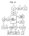
- Fig. 6 is a schematic block diagram showing the electrical configuration of the camera with the focus detecting device of the present embodiment.
- a solid-state image pickup device 70 composed of a CCD (corresponding to the CCD 64 shown in Fig. 4) releases an analog image signal, which is converted by an A/D converter 71 into a digital signal and sent to a digital signal processing unit 72.
- a VRAM 73 constituting memory means for storing image data to be displayed on an electronic view finder (EVF) 76; a D/A converter 74 for converting the image data from the VRAM 73 into an analog signal; and an LCD driver 75 for controlling the electronic view finder (EVF) 76 for displaying therein the image released from the VRAM 73.
- a buffer memory 77 composed for example of a DRAM for temporarily storing the digital image signal and various data; a memory 78 for storing the photographed image data; a system control unit 79 for controlling the entire camera; a display member 80 for displaying the setting of the camera and the control state thereof; an LCD driver 81 for driving the display member 80; a CCD driver 82 for driving the CCD 70; a lens control unit 83 for controlling the diaphragm and the light shading board for focus detection, the diaphragm for photographing and the focusing lens; and an operation switch 84 for setting the photographing mode and for detecting the shutter releasing operation.
- a buffer memory 77 composed for example of a DRAM for temporarily storing the digital image signal and various data
- a memory 78 for storing the photographed image data
- a system control unit 79 for controlling the entire camera
- a display member 80 for displaying the setting of the camera and the control state thereof
- an LCD driver 81 for driving the display member 80
- Figs. 7A to 7C illustrate the function of the focus detecting diaphragm 65 and the focus detecting light shading board 67 shown in Figs. 4 and 5.
- the focus detecting diaphragm 65 and the light shading board 67 are retracted, as shown in Fig. 7A, from a pupil area 69 corresponding to the full-open photographing diaphragm (passing area of the effective light beam).
- the focus detecting diaphragm 65 is inserted, by the motor 66, into the optical path of the photographing lens as shown in Figs. 7B and 7C, while the focus detecting light shading board 67 is moved by the motor 68 to cover either an aperture 65a or 65b of the diaphragm 65.
- the image signal L formed by the light beam transmitted by the left pupil is stored at first and then the image signal R formed by the light beam transmitted by the right pupil is stored, and the time interval of the storage of the image signals L and R is desirably as short as possible since a shorter interval reduces the error in the focus detection, resulting from the movement of the object image caused for example by hand vibration.
- the read-out of the pixel data if executed on the entire area of the CCD as in the photographing operation, will take a long time, thus prolonging the time interval between the storages of the image signals. For this reason, the storage of the image signal for focus detection is executed by the pixel read-out of a higher speed, as will be explained in the following.
- Fig. 8 is a schematic view of an interline CCD, wherein shown are pixels 31, vertical charge transfer elements 32, a horizonal charge transfer element 33, and an output unit 34.
- Signal charges obtained by photoelectric conversion in the pixels, are transferred to the vertical charge transfer elements 32, and are transferred in succession toward the horizontal charge transfer element 33 according to 4-phase driving pulses ⁇ V1, ⁇ V2, ⁇ V3, ⁇ V4.
- the horizontal charge transfer element 33 transfers the signal charges of a horizontal row, transferred from the vertical signal transfer elements 32, in succession toward the output unit 34 according to 2-phase driving pulses ⁇ H1, ⁇ H2, and the signal charges are converted in the output unit 34 into voltages and outputted.
- Fig. 9 is a schematic view of the image taking area of the CCD.
- the signal charges are read at a normal speed only in an area 41 used for the focus detection, but are sweep transferred at a higher speed in other areas 42, 43.
- Fig. 10 is a timing chart of a vertical synchronization period, in case the vertical charge transfer elements 32 of the aforementioned CCD are 4-phase driven.
- a vertical synchronization signal VD indicates the vertical blanking period by a low potential state
- a horizontal synchronization signal HD indicates the horizontal blanking period by a low potential state.
- 4-phase drive pulses ⁇ V1, ⁇ V2, ⁇ V3 and ⁇ V4 for the vertical charge transfer elements 32
- read-out pulses 51, 52 for transferring the signal charges, obtained by the photoelectric conversion in the pixels 31, to the vertical charge transfer elements 32.
- those 53 and 54 are high-speed sweep drive pulses for high-speed transfer of the signal charges in the vertical charge transfer elements 32 in the areas 42, 43 in Fig. 9, and are generated at a higher rate than in the ordinary drive pulses.
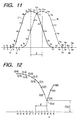
- Fig. 11 shows the image signal L formed by the light beam transmitted by the left pupil and the image signal R formed by the light beam transmitted by the right pupil, and the two image signals have a phase difference ⁇ .
- the image signal L is composed of values l 1 - l 23 , respectively corresponding to the signal charges of the pixels, while the image signal R is similarly composed of values r 1 - r 23 .
- a correlation C( ⁇ ) is calculated from the image signals L and R, according to the following formula: wherein max[l(i+6), r(i+ ⁇ +6)] means to select the larger of l(i+6) and r(i+ ⁇ +6), and ⁇ is varied from -6 to +6.
- Fig. 12 shows the change of the correlation C( ⁇ ), which becomes smaller as the value ⁇ approaches the phase difference ⁇ .
- An interpolating calculation is made on the correlations C(3), C(4) and C(5) to calculate C( ⁇ ) corresponding to the minimum correlation between C(3) and C(4), and a value ⁇ corresponding to C( ⁇ ) with the minimum correlation indicates the phase difference ⁇ .
- the phase difference of the image signals L and R can be calculated.
- the maximum and minimum values of ⁇ and the number of the pixel data are not limited to those in the foregoing embodiment.
- Figs. 13A and 13B show a case where the camera is inclined downwards by the hand vibration, in a period from the storage of the object image L formed by the light beam transmitted by the left pupil (Fig. 13A) to that of the object image R formed by the light beam transmitted by the right pupil (Fig. 13B), wherein the object image moves upwards as illustrated.
- an image signal R c at a position same as that of the image signal L c , looks at a lower position of the object than in the image signal L c , thus assuming a different shape.
- the correlation calculation based on the image signals of such different shapes, will lead to an erroneous phase difference.
- Fig. 14 shows the plotting of the minimum values C a ( ⁇ ), C b ( ⁇ ), C c ( ⁇ ), C d ( ⁇ ) and C e ( ⁇ ) of the correlations between the image signal L c shown in Fig. 13A and the image signals R a , R b , R c , R d and R e shown in Fig. 13B, wherein C b ( ⁇ ) is smallest because the image signal R b looks at a position same as that of the image signal L c . Consequently, the error caused by the hand vibration in the vertical direction can be significantly reduced by employing the phase difference ⁇ b between the image signals L c and R b for calculating the defocus amount.
- the correction is made in the pitch of a pixel line of the CCD, but the actual image movement by the hand vibration does not occur in such pitch.
- image signals of a pitch for example of 0.5 lines may be generated by interpolation.
- Fig. 15 shows a method of generating an image signal R ab of a pitch of 0.5 lines from the image signals R a and R b .
- R ab1 (R a1 + R b1 ) / 2
- the above-mentioned averaging can be replaced by a weighted averaging. In this manner it is rendered possible to achieve finer correction in the vertical direction, thereby improving the accuracy of focus detection.
- the minimum value C( ⁇ ) of the correlation does not vary much by the position of the image signal. Also the value of C( ⁇ ) varies to a certain extent by the noise component of the image signal. Consequently, in such case, the image signal at a position where the C( ⁇ ) becomes smallest may be of an erroneous position.
- Such erroneous judgment may occur in case the difference between the correlation C c ( ⁇ ) at a position corresponding to the image signal L c and the smallest C b ( ⁇ ) is smaller than a predetermined value.
- the image signal R c is adopted, and such method cannot improve the precision but can prevent further deterioration of the precision by the adverse effect of the erroneous judgment.
- This method is particularly effective in case the object has a pattern f diagonal lines, because, in such case, the value C( ⁇ ) remains same irrespective of the position while the phase difference ⁇ varies significantly depending on the position, whereby the possibility of erroneous judgment is rather high and such erroneous judgment leads to a significant deterioration in the precision of focus detection. Also in such object, the error in the phase difference caused by the vertical movement behaves similarly as that caused by the horizontal movement, and can be corrected similarly by the method for reducing the error in the horizontal direction, to be explained later.
- the vertical moving amount of the image signals L and R becomes larger with the focal length of the photographing lens and with the interval of the storages of the image signals L and R.
- the size of the calculating area, employed for the correction in the vertical direction can be selected according to the focal length information of the photographing lens and the interval of storage of the image signals, determined from the image accumulating time and the driving time of the focus detecting light shading board, in order to dispense with the calculation in an unnecessarily wide area, thereby reducing the calculation time.
- the amount of the image signal to be read can be reduced, thereby decreasing the required memory capacity and reducing the time required for signal read-out.
- Fig. 17 is a flow chart of a "shift range calculation" subroutine for setting the calculation area, which is activated at a step 2402 through a step 2401.
- a step 2402 calculates the image accumulation time TC from the luminance information of the object, then a step 2403 calculates the driving time TD of the focus detecting light shading board 67, and a next step 2404 calculates the interval TA of storage of the image signals as the sum of the above-mentioned accumulation time TC and the drive time TD.
- a step 2405 detects the focal length FA of the photographing zoom lens by reading a zoom encoder thereof.
- a step 2406 discriminates whether the storage interval TA of the image signals is smaller than 10 msec, and, if smaller, the sequence proceeds to a step 2407, but, if not, the sequence proceeds to a step 2412.
- the step 2407 discriminates whether the focal length FA is smaller than 30 mm, and, if smaller, the sequence proceeds to a step 2410, but, if not, the sequence proceeds to a step 2408.
- the step 2410 enters 1 as LS in order to set the calculation area so as to include an upper line and a lower line.
- a step 2808 discriminates whether FA is smaller than 60 mm, and, if smaller, the sequence proceeds to a step 2411, but, if not the sequence proceeds to a step 2409.
- the step 2411 enters 2 as LS in order to set the calculation area so as to include two upper lines and two lower lines, and the step 2409 enters 3 as LS.
- the variation of the calculation area LS according to the focal length of the photographing lens and the storage interval of the image signals allows to dispense with the unnecessary calculation and the unnecessary image signal read-out.
- the calculation area LS is naturally made smaller (with fewer number of lines) in case of a shorter focal length of the photographing lens or a shorter storage interval of the image signals, which reduce the influence of the hand vibration.
- Fig. 18 is a chart showing the principle of eliminating the detection error, caused by the hand vibration, in an assumed case in which the object image moves from left to right at a constant speed because of the hand vibration. It is assumed that the image signals are stored at a constant interval. L 1 , R 2 and L 3 indicate the actually stored image signals, and R 1 , L 2 and R 3 indicate the other image signals if they are stored at the same timings.
- phase difference ⁇ allows to eliminate the error in focus detection, resulting from the object movement of a constant speed, caused by the hand vibration. Since the aforementioned condition stands in case the interval of image signal storages is sufficiently short, this method is very effective when the driving speed of the focus detecting light shading board 67 is fast and the image accumulation time is short.
- the time required for driving the focus detecting light shading board 67 from the right pupil to the left pupil of the focus detecting diaphragm 65 is equal to that from the left pupil to the right pupil and that the image accumulation time of the CCD remains same for all the three image signals, so that the storages of the image signals are realized with a same interval, but there may be a fluctuation in the driving time of the focus detecting light shading board 67 or in the image accumulation time.
- a calculation method in case the interval of the storages of the image signals is varied.
- Fig. 19 shows the relationship between the image signal storage time and the position of the object image, wherein T 12 is the interval of the storages of the image signals L 1 and R 2 , T 23 is the interval of the storages of the image signals R 2 and L 3 , and ⁇ 12 and ⁇ 23 are respectively the phase differences between L 1 and R 2 and between R 2 and L 3 .
- the inclination of a solid line, representing the image signals L is indicated by: ( ⁇ 23 - ⁇ 12 ) / (T 12 + T 23 ) and the phase difference between L 1 and L 2 is represented by: T 12 ( ⁇ 23 - ⁇ 12 ) / (T 12 + T 23 )
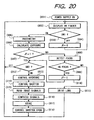
- Fig. 20 is a flow chart showing the main control sequence of the entire camera.
- a power switch When a power switch is turned on to activate the various circuits, the sequence proceeds from a step 001 to a step 002 to execute display on the view finder. More specifically, the image signal is stored by the CCD and displayed on the electronic view finder (EVF) after various signal processings.
- EVF electronic view finder
- a next step 003 detects the state of a switch SW1 which is to be turned on by the depression by a first stroke of a shutter release button, and, if it is off, the sequence proceeds to a step 004 to initialize a flag JF for detecting the state of the focusing. If the switch SW1 is on, the sequence proceeds to a step 005.
- a step 005 calculates the luminance of the object, based on the output of the image signal stored by the CCD, the gain of the signal processing circuit, the image accumulation time of the CCD and the F-number of the photographing lens.
- a next step 006 calculates appropriate shutter speed (exposure time) and aperture stop (F-value), based on the calculated object luminance, the photographing mode of the camera and the exposure correcting information, and stores thus calculated values in a predetermined memory area. At the shutter releasing operation to be explained later, the shutter and the diaphragm are controlled according to the data thus stored in the memory area.
- a step 008 is a "focus detection" subroutine for detecting the defocus amount of the photographing lens, which will be explained later in detail.
- a next step 009 compares the defocus amount detected in the step 008 with a permissible defocus amount determined from the diameter of a permissible fluctuation circle and the F-number of the photographing lens, and, if the former is smaller, indicating an in-focus state, the sequence proceeds to a step 010 to enter 1 in the flag JF thereby memorizing the in-focus state, and then the sequence proceeds to a step 012.
- a step 011 executes the focusing operation by driving the focusing lens group of the photographing lens so as to cancel the defocus amount detected in the foregoing step 008, and then the sequence returns to the step 002.
- a step 012 discriminates the state of a switch SW2 which is to be turned on by the depression of the shutter release button by a second stroke, and, if it is off, the sequence returns to the step 002, but, if it is on, the sequence proceeds to a step 013 for effecting the shutter releasing operation.
- a step 013 controls the lens diaphragm to a diaphragm value calculated in the step 006, and a next step 014 closes the shutter, resets the charges in the CCD and controls the shutter with the shutter time calculated in the step 006, thereby executing the exposure operation of the CCD.
- a next step 015 drives the CCD to release the image signal and applies a predetermined signal processing thereon.
- a next step 016 executes a compression process, and the compressed image signal is stored in the memory medium in a step 017.
- a step 018 opens the shutter to restore the initial state, and then the sequence returns to the step 002.
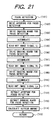
- the sequence proceeds, through a step 101, to a step 102.
- a step 102 moves the focus detecting diaphragm 65, which has been in a state shown in Fig. 7A, into the optical path of the photographing lens
- a next step 103 moves the focus detecting light shading board 67, which has been in a state shown in Fig. 7A, into the optical path of the photographing lens.
- the focus detecting diaphragm 65 and the focus detecting light shading board 67 are shifted to a state shown in Fig. 7B, whereby the light beam transmitted by the left aperture 65a of the diaphragm 65 alone is focused on the CCD.
- a step 104 executes the image accumulation in the CCD, and a next step 105 reads the image signal L 1 accumulated in the step 104 and stores it in a predetermined memory area. Different from the ordinary read-out operation, the read-out operation of the image signal L 1 is executed only in an area necessary for the focus detection and the image signal in the unnecessary areas is discarded at a high speed as explained in the foregoing, whereby the reduction in the image signal read-out time can be realized.
- a next step 106 moves again the focus detecting light shading board 67 to a state shown in Fig. 7C, whereby the light beam transmitted by the right aperture 65b of the diaphragm 65 alone is focused on the CCD.
- a next step 107 executes the image accumulation as in the foregoing step 104, and a step 108 reads and stores the image signal R 2 in a predetermined memory area, as in the foregoing step 105.
- a next step 109 moves again the focus detecting light shading board 67 to a state shown in Fig. 7B, whereby the light beam transmitted by the left aperture 65a of the diaphragm 65 alone is focused on the CCD.
- a next step 110 executes the image accumulation, and a step 111 reads and stores the image signal L 3 in a predetermined memory area.
- a step 112 retracts the focus detecting diaphragm 65, and a step 113 retracts the focus detecting light shading board 67. After the steps 112 and 113, there is restored the initial state shown in Fig. 7A.
- a step 114 is a "defocus amount calculation” subroutine, which calculates the defocus amount of the photographing lens, based on the image signals L 1 , R 2 and L 3 , as will be explained later in more details. After the step 114, the "focus detection" subroutine is terminated in a step 115.
- the image accumulating operations in the aforementioned steps 104, 107 and 110 may be executed with a same accumulation time and a same gain to equalize the output levels of the image signals, thereby increasing the correlation in the correlation calculation and obtaining a high and stable accuracy of the detection.
- step 205 the present subroutine is terminated by a step 206.
- Fig. 23 shows a flow chart of the "focus detection" subroutine. When it is called in the step 008 in Fig. 20, the sequence proceeds to a step 302 through a step 301.
- Steps 302 and 303 drive the focus detecting diaphragm 65 and the focus detecting light shading board 67 to a state shown in Fig. 7B as in the steps 102 and 103 in Fig. 20, thereby preparing for the focus detecting operation.
- a next step 304 memorizes the starting time of the image accumulating operation for the image signal L 1 , by storing the count TIMER of a self-running timer of the system control unit in a RAM memory area T 1 .
- a next step 305 executes the accumulation of the image signal L 1 , and a step 306 executes the read-out thereof.
- a step 307 moves the light shading board 67 to a state shown in Fig. 7C, and a next step 308 memorizes the starting time of the accumulation of the image signal R 2 , by storing the timer count TIMER in a memory area T 2 .
- steps 309, 310 executes the accumulation and the read-out of the image signal R 2 .
- a step 311 moves the light shading board 67 to a state shown in Fig. 7B, and a next step 312 memorizes the starting time of the accumulation of the image signal L 3 , by storing the timer count TIMER in a memory area T 3 . Then steps 313, 314 executes the accumulation and the read-out of the image signal L 3 .
- Steps 315 and 316 retract the focus detecting diaphragm 65 and the focus detecting light shading board 67 to a state shown in Fig. 7A, and a step 317 calculates the defocus amount. Then a step 318 terminates the present subroutine.
- Fig. 24 shows a "defocus amount calculation" subroutine to be used in case the interval of the image signal storages varies.
- this subroutine is called in the step 317 in Fig. 23, the sequence proceeds to a step 402 through a step 401.
- a step 402 calculates the interval T 12 of the starts of accumulations of the image signals L 1 and R 2
- a step 403 similarly calculates the interval T 23 of the starts of accumulations of the image signals R 2 and L 3 .
- a step 404 calculates the phase difference ⁇ 12 of the image signals L 1 and R 2 by correlation calculation
- a step 405 similarly calculates the phase difference ⁇ 23 of the image signals R 2 and L 3 .
- a next step 407 calculates the defocus amount DF of the photographing lens, based on the phase difference ⁇ determined in the foregoing step 406, the sensitivity K of the focus detection system, and the pixel pitch P of the CCD. After this step, the present subroutine is terminated by a step 408.
- the start of the charge accumulating operation can wait until the lapse of such upper limit time even after the driving of the light shading board is completed, as long as the driving time is sufficiently short. It is therefore possible to maintain a constant interval of the starts of the accumulating operations, in such case, by employing a same accumulating time, thereby easily simplifying the calculation process. Also, the presence of a timer for stabilizing the interval of the starts of the charge accumulating operations provides an advantage of dispensing with the means for detecting the completion of driving of the focus detecting light shading board 67.
- four image signals are stored time-sequentially, in order to eliminate the detection error, caused by a constant-acceleration movement of the optical image resulting from the hand vibration or from the movement of the object.
- Fig. 25 shows the principle of elimination, in the present embodiment, of the detection error resulting from the hand vibration, wherein the object image is assumed to move from left to right at a constant acceleration caused by the hand vibration, and it is also assumed that the image signals are stored at a constant interval.
- L 1 , R 2 , L 3 and R 4 indicate the actually stored image signals, and R 1 , L 2 , R 3 and L 4 indicate the other image signals if they are stored at the same timings.
- the object image moves by a distance ⁇ m1 in the period from the storage of the image signal L 1 to that of the image signal R 2
- This error ⁇ d1 results from the variation in the speed, induced by the acceleration.
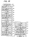
- Fig. 26 shows a flow chart of a "focus detection" subroutine in case the interval of the image signal storages always varies.
- this subroutine is called, the sequence proceeds, through a step 501, to a step 502.
- Steps 502 and 503 drive the focus detecting diaphragm 65 and the focus detecting light shading board 67 to a state shown in Fig. 7B, thereby preparing for the focus detecting operation.
- a next step 504 memorizes the starting time of the charge accumulating operation for the image signal L 1 , by storing the count TIMER of a self-running timer of the system control unit in a RAM memory area T 1 .
- a next step 505 executes the accumulation of the image signal L 1 , and a step 506 executes the read-out thereof.
- a step 507 moves the light shading board 67 to a state shown in Fig. 7C.
- a next step 508 memorizes the starting time of the accumulation of the image signal R 2 , by storing the timer count TIMER in a memory area T 2 . Then a step 509 executes the accumulation of the image signal R 2 , and a step 510 executes the read-out of the image signal R 2 .
- a step 511 moves the light shading board 67 to a state shown in Fig. 7B, then a step 512 memorizes the starting time of the accumulation of the image signal L 3 , by storing the timer count TIMER in a memory area T 3 , a step 513 executes the accumulation of the image signal L 3 , and a step 514 executes the read-out of the image signal L 3 .
- a step 515 moves the light shading board 67 to a state shown in Fig. 7C, then a step 516 memorizes the starting time of the accumulation of the image signal R 4 , by storing the timer count TIMER in a memory area T 4 , a step 517 executes the accumulation of the image signal R 4 , and a step 518 executes the read-out of the image signal R 4 .
- steps 519, 520 drive the focus detecting diaphragm 65 and the focus detecting light shading board 67 to a state shown in Fig. 7A.
- a next step 521 calculates the defocus amount, and a step 522 terminates the present subroutine.
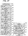
- Fig. 27 shows a "defocus amount calculation” subroutine.
- this subroutine is called in the step 521 in Fig. 26, the sequence proceeds to a step 602 through a step 601.
- a step 602 calculates the interval T 12 of the starts of accumulations of the image signals L 1 and R 2 , then a step 603 similarly calculates the interval T 23 of the starts of accumulations of the image signals R 2 and L 3 , and a step 604 calculates the interval T 34 of the starts of accumulations of the image signals L 3 and R 4 .
- a step 605 calculates the phase difference ⁇ 12 of the image signals L 1 and R 2 by correlation calculation, then a step 606 similarly calculates the phase difference ⁇ 23 of the image signals R 2 and L 3 , and a step 607 calculates the phase difference ⁇ 34 of the image signals L 3 and R 4 .
- Steps 608, 609 calculate the phase differences ⁇ d1 , ⁇ d2 by eliminating the error of the constant-speed component, and a step 610 calculates the phase difference ⁇ by eliminating the error of the constant-acceleration component.
- a next step 611 calculates the defocus amount DF of the photographing lens, based on the phase difference ⁇ after the elimination of the error of the constant-acceleration component, the sensitivity K of the focus detection system, and the pixel pitch P of the CCD. Thereafter, the present subroutine is terminated by a step 612.
- Fig. 28 is a flow chart showing the focus detecting subroutine in case the above-explained regularity is present in the intervals of the starts of the charge accumulating operations. This flow chart will not be explained further as it is same as the flow chart shown in Fig. 26, except that the start time T 4 for the accumulation of the image signal R 4 is unnecessary and is not, therefore, measured.
- a step 802 calculates the interval T 12 of the starts of accumulations of the image signals L 1 and R 2
- a step 803 calculates the interval T 23 of the starts of accumulations of the image signals R 2 and L 3 .
- steps 804 to 806 calculate the phase differences ⁇ 12 , ⁇ 23 and ⁇ 34 similarly to the steps 605 to 607 in Fig. 34, then a step 807 calculates the phase difference ⁇ , and a step 808 calculates the defocus amount DF of the photographing lens, based on the phase difference ⁇ , the sensitivity K of the focus detection system, and the pixel pitch P of the CCD. Thereafter, the present subroutine is terminated by a step 809.
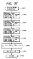
- Fig. 30 is a flow chart of the focus detection subroutine in case the intervals of the starts of the charge accumulations are constant. This flow chart will not be explained in detail, since it is similar to that shown in Fig. 26, except that the accumulation starting times are not read because the measurement of the intervals is not necessary.
- the driving of the focus detecting diaphragm 65 and the focus detecting light shading board 67 and the accumulation and read-out of the image signals L 1 , R 2 , L 3 and R 4 are executed in a similar manner as in the flow chart shown in Fig. 26.
- step 917 When a "defocus amount calculation" subroutine is called in a step 917, the sequence proceeds, through a step 1001, to a step 1002 to execute the "defocus amount calculation" subroutine.
- Steps 1002 to 1004 calculate the phase differences ⁇ 12 , ⁇ 23 and ⁇ 34 by correlation calculations similar to those in the steps 605 to 607 in Fig. 26, then a step 1005 calculates the phase difference ⁇ by eliminating the error caused by the constant-acceleration movement, and a step 1006 calculates the defocus amount DF, based on the phase difference 6, the sensitivity K of the focus detection system, and the pixel pitch P of the CCD. Thereafter, the present subroutine is terminated by a step 1007.
- the intervals of the starts of image accumulations can be given a regularity or made constant by providing a stabilizing timer which starts the image accumulating operation after the lapse of a predetermined time even if the driving of the focus detecting light shading board 67 is completed within a short time.
- the expiration time of such stabilizing timer need only be longer than the maximum driving time. Also the presence of such stabilizing timer allows to dispense with detection means for detecting the completion of driving of the light shading board 67.
- five image signals are time-sequentially stored, and the movement of the optical image, caused by the hand vibration or the movement of the object, is approximated by a second-order function thereby reducing the error in focus detection resulting from such movement.
- Fig. 32 is a chart showing the error reducing method of the present third embodiment, wherein the object position y is represented in the ordinate, as a function of time t in the abscissa.
- the camera stores image signal L 1 , R 2 , L 3 , R 4 and L 5 in time-sequential manner, while alternately switching the pupils. It is assumed that the movement of the object image in a period from the storage of the image signal L 1 to that of the image signal L 5 can be approximated by a second-order function.
- y At + Bt 2 passing through the positions of the image signals L 1 , L 3 and L 5 , then the positions of imaginary image functions L 2 , L 4 are determined by an interpolation utilizing such second-order function, and the average of the phase difference between L 2 and R 2 and that between L 4 and R 4 is adopted as the final target phase difference ⁇ .
- the foregoing shows the calculation method for the phase difference ⁇ , in case the intervals of the image signal storages constantly vary.
- A -3 ⁇ 12 +3 ⁇ 23 + ⁇ 34 - ⁇ 45 2( T 12 + T 23 )
- B ⁇ 12 - ⁇ 23 - ⁇ 34 + ⁇ 45 2( T 12 + T 23 ) 2
- ⁇ A ⁇ (3 ⁇ T 12 + T 23 )+ B ⁇ ( T 2 12 +(2 ⁇ T 12 + T 23 ) 2 )+2 ⁇ 12 - ⁇ 23 + ⁇ 34 2
- the foregoing shows the calculation method for the phase difference ⁇ in case the intervals of the image signal storages have regularity.
- calculation formulas can be significantly simplified by giving regularity to the intervals of the image signal storages or selecting such intervals at a same value.
- Fig. 33 is a flow chart showing the focus detection subroutine in case the intervals of the image signal storages vary constantly.
- this subroutine is called, the sequence proceeds, through a step 1101, to a step 1102.
- Steps 1102 and 1103 respective drive the focus detecting diaphragm 65 and the focus detecting light shading board 67 to a state shown in Fig. 7B.
- a next step 1104 memorizes the starting time of the charge accumulating operation for the image signal L 1 , by storing the count TIMER of a self-running timer of the system control unit in a RAM memory area T 1 .
- a next step 1105 executes the accumulation of the image signal L 1 , and a step 1106 executes the read-out thereof.
- a step 1107 moves the light shading board 67 to a state shown in Fig. 7C.
- a next step 1108 memorizes the starting time of the accumulation of the image signal R 2 , by storing the timer count TIMER in a memory area T 2 .
- a step 1109 executes the accumulation of the image signal R 2
- a step 1110 executes the read-out of the image signal R 2 .
- a step 1111 moves the light shading board 67 to a state shown in Fig. 7B, then a step 1112 memorizes the starting time of the accumulation of the image signal L 3 , by storing the timer count TIMER in a memory area T 3 , a step 1113 executes the accumulation of the image signal L 3 , and a step 1114 executes the read-out of the image signal L 3 .
- a step 1115 moves the light shading board 67 to a state shown in Fig. 7C, then a step 1116 memorizes the starting time of the accumulation of the image signal R 4 , by storing the timer count TIMER in a memory area T 4 , a step 1117 executes the accumulation of the image signal R 4 , and a step 1118 executes the read-out of the image signal R 4 .
- a step 1119 moves the light shading board 67 to a state shown in Fig. 7B, then a step 1120 memorizes the starting time of the accumulation of the image signal L 5 , by storing the timer count TIMER in a memory area T 5 , a step 1121 executes the accumulation of the image signal L 5 , and a step 1122 executes the read-out of the image signal L 5 .
- steps 1123, 1124 drive the focus detecting diaphragm 65 and the focus detecting light shading board 67 to a state shown in Fig. 7A.
- a next step 1125 calculates the defocus amount, and a step 1126 terminates the present subroutine.
- Steps 1202 to 1205 calculate the intervals T 12 , T 23 , T 34 , T 45 of the starts of accumulations of the image signals, then steps 1206 to 1209 calculate the phase differences ⁇ 12 , ⁇ 23 , ⁇ 34 , ⁇ 45 of the image signals by correlation calculation. Then a step 1210 calculates the coefficient A of the first-order term of the second-order function, and a step 1211 calculates the coefficient B of the second-order term. A next step 1212 calculates the phase difference ⁇ , by the approximation with the second-order function, and a step 1213 calculates the defocus amount DF of the photographing lens, based on the phase difference ⁇ , the sensitivity K of the focus detection system, and the pixel pitch P of the CCD. Thereafter, the present subroutine is terminated by a step 1214.
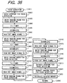
- Fig. 35 is a flow chart showing the focus detecting subroutine in case the above-explained regularity is present in the intervals of the starts of the charge accumulating operations. This flow chart will not be explained further as it is same as the flow chart shown in Fig. 33, except that the start times T 4 , T 5 for the accumulation of the image signals R 4 , R 5 are unnecessary and are not, therefore, measured.
- a step 1402 calculates the interval T 12 of the starts of accumulations of the image signals L 1 and R 2
- a step 1403 calculates the interval T 23 of the starts of accumulations of the image signals R 2 and L 3 .
- steps 1404 to 1407 calculate the phase differences ⁇ 12 , ⁇ 23 , ⁇ 34 and ⁇ 45 similarly to the steps 1206 to 1209 in Fig. 34
- a step 1408 calculates the coefficient A of the first-order term of the second-order function
- a step 1409 calculates the coefficient B of the second-order term.
- a step 1410 calculates the phase difference ⁇ determined by the approximation with the second-order function, and a step 1411 calculates the defocus amount DF of the photographing lens, based on the phase difference ⁇ , the sensitivity K of the focus detection system, and the pixel pitch P of the CCD. Thereafter, the present subroutine is terminated by a step 1412.
- Fig. 37 is a flow chart of the focus detection subroutine in case the intervals of the starts of the charge accumulations are constant. This flow chart will not be explained in detail, since it is similar to that shown in Fig. 33, except that the accumulation starting times are not read because the measurement of the intervals is not necessary.
- the driving of the focus detecting diaphragm 65 and the focus detecting light shading board 67 and the accumulation and read-out of the image signals L 1 , R 2 , L 3 , R 4 and L 5 are executed in a similar manner as in the flow chart shown in Fig. 33.
- Steps 1602 to 1605 calculate the phase differences ⁇ 12 , ⁇ 23 , ⁇ 34 and ⁇ 45 by correlation calculations similar to those in the steps 1206 to 1209 in Fig. 34, then a step 1607 calculates the phase difference ⁇ corrected by approximation with the second-order function. Then a step 1607 calculates the defocus amount DF, based on the phase difference ⁇ , the sensitivity K of the focus detection system, and the pixel pitch P of the CCD. Thereafter, the present subroutine is terminated by a step 1608.
- a stabilizing timer which starts the image accumulating operation after the lapse of a predetermined time even if the driving of the focus detecting light shading board 67 is completed within a short time, thereby easily giving regularity to the intervals of the start times of the image accumulations or maintaining such intervals constant.
- the expiration time of such stabilizing timer need only be longer than the maximum driving time. Also the presence of such stabilizing timer allows to dispense with detection means for detecting the completion of driving of the light shading board 67.
- the foregoing embodiments utilize 3 to 5 image signals for calculating the phase difference, corrected for the object movement on the CCD, resulting from the movement of the object or from the hand vibration.
- a fourth embodiment of the present invention selects the number of the image signals and the calculation method therefor, according to the focal length of the photographing lens and the intervals of the storages of the image signals.
- Fig. 39 is a simulated chart showing the relationship between the interval of the image signal storages and the focal length of the photographing lens, for which the detection error caused by the hand vibration becomes equal to the permissible error (permissible focal length), in various countermeasures for reducing the influence of the hand vibration.
- the image signals L 1 and R 2 have a phase difference ⁇ 12
- the image signals L 3 and R 2 have a phase difference ⁇ 23
- the image signals L 3 and R 4 have a phase difference ⁇ 34
- the image signals L 5 and R 4 have a phase difference ⁇ 45
- the intervals of the image signal storages are constant.
- This chart indicates that the permissible focal length becomes larger for a shorter interval of the storage of the image signals and for a larger number of the image signals employed in a single calculation.
- the present embodiment is, therefore, to minimize the time required for the focus detection by selecting a minimum necessary number of the image signals required for securing the necessary precision and a matching calculation method, according to the focal length of the actually employed photographing lens, the image accumulation time and the driving time of the focus detecting light shading board 67.
- the countermeasure 4 is more effective, in comparison with the countermeasure 3, when the interval of the image signal storages is longer than 15 msec, but is less effective in case the interval does not exceed 15 msec. For this reason, the countermeasure 4 or 3 is employed respectively in case the storage interval is longer or shorter than 15 msec.
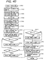
- Fig. 40 shows a flow chart of a "focus detection" subroutine. When it is called, the sequence proceeds to a step 1702 through a step 1701.
- a step 1702 calculates the accumulation time TC and the gain at the focus detection, based on the object luminance and the aperture value of the focus detecting diaphragm 65 obtained in a light metering subroutine of the step 005 shown in Fig. 20, then a step 1703 reads the drive time TD for the focus detecting light shading board 67 for pupil switching, from the data stored in the ROM, and a step 1704 calculates the interval of the image signal storages as the sum of TC and TD.
- a step 1705 detects the focal length FA of the photographing lens, by reading the zoom encoder of the zoom lens.
- a step 1706 calculates the number NA of the image signals required for a single focus detection, from the interval TA of the image signal storages and the focal length FA of the photographing lens. This calculation method will be explained later in more details.
- Steps 1707 and 1708 respectively drive the focus detecting diaphragm 65 and the focus detecting light shading board 67 to the state shown in Fig. 7B.
- a step 1713 is an "image signal storage 2" subroutine for storage two image signals; a step 1714 is an “image signal storage 3" subroutine for storage three image signals; a step 1715 is an “image signal storage 2" subroutine for storage two image signals; and a step 1712 is an "image signal storage 5" subroutine for storage five two image signals.
- steps 1712 to 1715 the sequence proceeds to steps 1716, 1717 for respectively driving the focus detecting diaphragm 65 and the focus detecting light shading board 67 to the state shown in Fig. 7A.
- a next step 1718 calculates the defocus amount of the photographing lens by a "defocus amount calculation” subroutine, and a step 1719 terminates this subroutine.
- the details of the "defocus amount calculation” subroutine will be explained later.
- Figs. 41 and 42 are flow charts of the "image signal number NA calculating" subroutine.
- this subroutine is called in the step 1706 shown in Fig. 40, the sequence proceeds to a step 1802 through a step 1801.
- a step 1802 discriminates whether the interval TA of the image signal storages is shorter than 5 msec, and, if TA ⁇ 5 msec, the sequence proceeds to a step 1803, but, if not, the sequence proceeds to a step 1810.
- the step 1810 discriminates whether the interval TA of the image signal storages is shorter than 10 msec, and, if TA ⁇ 10 msec, the sequence proceeds to a step 1811, but, if not, the sequence proceeds to a step 1818.
- the step 1818 discriminates whether the interval TA of the image signal storages is shorter than 15 msec, and, if TA ⁇ 15 msec, the sequence proceeds to a step 1819, but, if not, the sequence proceeds to a step 1824.
- the step 1824 discriminates whether the interval TA of the image signal storages is shorter than 20 msec, and, if TA ⁇ 20 msec, the sequence proceeds to a step 1825, but, if not, the sequence proceeds to a step 1830.
- the sequence proceeds to the step 1803 in case of TA ⁇ 5 msec, to the step 1811 in case of 5 msec ⁇ TA ⁇ 10 msec, to the step 1819 in case of 10 msec ⁇ TA ⁇ 15 msec, to the step 1825 in case of 15 msec ⁇ TA ⁇ 20 msec, or to the step 1830 in case of 20 msec ⁇ TA ⁇ 23 msec.
- the step 1803 discriminates whether the focal length FA of the photographing lens is smaller than 11 mm, and, if FA ⁇ 11 mm, the sequence proceeds to a step 1807, but, if not, the sequence proceeds to a step 1804.
- the step 1804 discriminates whether FA is smaller than 83 mm, and, if FA ⁇ 83 mm, the sequence proceeds to a step 1808 for entering 3 as NA, but, if not, the sequence proceeds to a step 1805.
- the step 1805 discriminates whether FA is smaller than 207 mm, and, if FA ⁇ 207 mm, the sequence proceeds to a step 1809 for entering 4 as NA, but, if not, the sequence proceeds to a step 1806 for entering 5 as NA.
- a step 1833 terminates this subroutine.
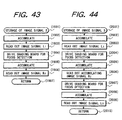
- Fig. 43 shows a flow chart of the "image signal storage 2" subroutine for storage two image signals L 1 and R 2 .
- this subroutine is called in the step 1713 shown in Fig. 40, the sequence proceeds to a step 1902 through a step 1901.
- a step 1902 executes accumulation of the image signal L 1 , and a next step 1903 executes read-out thereof.
- a step 1904 drives the focus detecting light shading board 67 to the state shown in Fig. 7C, then a step 1905 executes accumulation of the image signal R 2 , a step 1906 executes read-out thereof, and a step 1907 terminates this subroutine.
- Fig. 44 shows a flow chart of the "image signal storage 3" subroutine for storage three image signals L 1 , R 2 and L 3 .
- the interval of the image signal storages is constant, namely the drive time TD of the focus detecting light shading board 67 and the accumulation time TC are constant. Consequently the measurement of the interval is unnecessary and is not, therefore, conducted.
- a step 2002 executes accumulation of the image signal L 1 , and a next step 2003 executes read-out thereof.
- a step 2004 drives the focus detecting light shading board 67 to the state shown in Fig. 7C, and steps 2005 and 2006 execute accumulation and read-out of the image signal R 2 .
- a step 2007 drives again the focus detecting light shading board 67 to the state shown in Fig. 7B, and steps 2008 and 2009 execute accumulation and read-out of the image signal L 3 . Then a step 2010 terminates this subroutine.
- Fig. 45 shows a flow chart of the "image signal storage 4" subroutine for storage four image signals L 1 , R 2 , L 3 and R 4 . Also in the present case, it is assumed that the interval of the image signal storages is constant, so that the measurement of the interval is not conducted.
- the "image signal storage 4" subroutine is called in the step 1715 shown in Fig. 40, the sequence proceeds to a step 2102 through a step 2101.
- Steps 2102 and 2103 execute accumulation and read-out of the image signal L 1 .
- a step 2104 drives the focus detecting light shading board 67 to the state shown in Fig. 7C, and steps 2105 and 2106 execute accumulation and read-out of the image signal R 2 .
- a step 2107 drives again the focus detecting light shading board 67 to the state shown in Fig. 7B, and steps 2108 and 2109 execute accumulation and read-out of the image signal L 3 .
- a step 2110 drives again the focus detecting light shading board 67 to the state shown in Fig. 7C, and steps 2111 and 2112 execute accumulation and read-out of the image signal R 4 . Then a step 2113 terminates this subroutine.
- Fig. 46 shows a flow chart of the "image signal storage 5" subroutine for storage five image signals L 1 , R 2 , L 3 , R 4 and L 5 . Also in the present case, it is assumed that the interval of the image signal storages is constant, so that the measurement of the interval is not conducted.
- the "image signal storage 5" subroutine is called in the step 1712 shown in Fig. 40, the sequence proceeds to a step 2202 through a step 2201.
- Steps 2202 and 2203 execute accumulation and read-out of the image signal L 1 .
- a step 2204 drives the focus detecting light shading board 67 to the state shown in Fig. 7C, and steps 2205 and 2206 execute accumulation and read-out of the image signal R 2 .
- a step 2207 drives again the focus detecting light shading board 67 to the state shown in Fig. 7B, and steps 2208 and 2209 execute accumulation and read-out of the image signal L 3 .
- a step 2210 drives again the focus detecting light shading board 67 to the state shown in Fig. 7C, and steps 2211 and 2212 execute accumulation and read-out of the image signal R 4 .
- a step 2213 drives again the focus detecting light shading board 67 to the state shown in Fig. 7B, and steps 2214 and 2215 execute accumulation and read-out of the image signal L 5 . Then a step 2216 terminates this subroutine.
- Fig. 47 shows a "defocus amount calculation” subroutine, which switches the calculation formula according to the photographing conditions, in order to secure the necessary precision of detection.
- the step 2303 calculates the phase difference ⁇ 12 of the image signals L 1 and R 2 by correlation calculation, then a step 2304 calculates the phase difference ⁇ 23 of the image signals R 2 and L 3 , a step 2305 calculates the phase difference ⁇ 34 of the image signals L 3 and R 4 , and a step 2306 calculates the phase difference ⁇ 45 of the image signals R 4 and L 5 .
- a next step 2307 discriminates whether the interval TA of the image signal storages is longer than 15 msec, and if TA > 15 msec, the sequence proceeds to a step 2308, but, if not, the sequence proceeds to a step 2309. This is because, as shown in Fig. 39, the permissible focal length is larger in the countermeasure 4 than in the countermeasure 3 in case the interval of the image signal storages is longer than 15 msec.
- the sequence proceeds to the step 2308 to execute the calculation according to the countermeasure 4, but, in case the interval TA is shorter than 15 msec, the sequence proceeds to the step 2309 to execute the calculation according to the countermeasure 4, thereby calculating the phase difference ⁇ to be employed in the calculation of the defocus amount.
- a step 2311 calculates the phase difference ⁇ 12 of the image signals L 1 and R 2 , then a step 2312 calculates the phase difference ⁇ 23 of the image signals R 2 and L 3 , and a step 2313 calculates the phase difference ⁇ 34 of the image signals L 3 and R 4 .
- a next step 2314 calculates the phase difference ⁇ to be employed in the calculation of the defocus amount, according to the calculation process of the countermeasure 2.
- a step 2316 calculates the phase difference ⁇ 12 of the image signals L 1 and R 2
- a step 2317 calculates the phase difference ⁇ 23 of the image signals R 2 and L 3
- a next step 2318 calculates the phase difference ⁇ to be employed in the calculation of the defocus amount, according to the calculation process of the countermeasure 1.
- a step 2319 calculates the phase difference ⁇ 12 of the image signals L 1 and R 2 , and a step 2320 enters ⁇ 12 as the phase difference ⁇ to be employed in the calculation of the defocus amount.
- step 2308, 2309, 2314, 2318 or 2320 the sequence proceeds to a step 2321 for calculating the defocus amount DF according the phase difference ⁇ , the sensitivity K of the focus detecting system and the pixel pitch P of the CCD, and a step 2322 terminates this subroutine.
- the foregoing embodiment capable of selecting the minimum number of the image signals and the calculation method capable of securing the necessary precision of detection, according to the photographing conditions (focal length of photographing lens, and interval of image signal storages), can dispense with the storage operation for the unnecessary image signals, thereby reducing the time required for focus detection and also reducing the electric power consumption.
- CCD solid-state image pickup device
- such CCD is not limited to an area sensor but can also be composed of a line sensor.
- the means for changing the shape of the pupil is composed of the focus detecting diaphragm 65, but it may also be composed of a diaphragm utilizing physical property such as a diaphragm composed of an LCD.
- the entry and retraction of the focus detecting light shading board 67 into and from the photographing optical path are executed by a motor, but an actuator such as a plunger may also be used for this purpose.
- the moving amount detection range for detecting the moving amount of the object in the vertical direction (perpendicular to the direction of arrangement of the pupil areas), is determined, as explained with reference to Fig. 17, in consideration of the focal length of the photographing lens, the interval of the image signal storages, the image signal accumulating time and the driving time of the focus detecting light shading board 67 (means for changing the pupil shape), but the effect of a certain level can be obtained by considering at least one of these information.
- the driving time of the light shading board is almost constant and this information is therefore almost negligible.
- the number of the image signals to be employed for detecting the moving amount of the object in the vertical direction is determined, as explained with reference to Figs. 41 and 42, in consideration of the focal length of the photographing lens, the interval of the image signal storages, the image signal accumulating time and the driving time of the focus detecting light shading board 67 (means for changing the pupil shape), but the effect of a certain level can be obtained by considering at least one of these information.
- the foregoing embodiments intend to reduce the error in the focus detection, resulting from the hand vibration or from the movement of the object, for example by storage the image signals L 1 , R 2 , L 3 , R 4 and L 5 and utilizing the phase differences between the image signals L 1 and R 2 , between R 2 and L 3 , between L 3 and R 4 and between R 4 and L 5 , but such reduction in the error of focus detection can also be attained by such calculations plural times and taking the average or the weighted average of the obtained results.
- the present invention has been explained by its application to a digital camera, it is likewise applicable also to a video camera of a conventional camera utilizing a silver halide-based film.
- This invention discloses a focus detecting device for determining the focus state of an imaging optical system, of a type for time-sequentially entering light beams, transmitted by different areas of an imaging optical system, into sensor means and detecting the phase difference between the image signal obtained from the sensor means corresponding to such time-sequentially entered light beams.
- the device of the present invention determines the positional difference in the vertical direction of the light beams (images) time-sequentially entering the sensor means, and determines the storage positions of the outputs (image signals) from the sensor means corresponding to the light beams (images) of the respective areas, thereby enabling exact focus detection even in case the images are received in vertically different positions on the sensor means.
Applications Claiming Priority (6)
| Application Number | Priority Date | Filing Date | Title |
|---|---|---|---|
| JP353379/96 | 1996-12-17 | ||
| JP35337996A JPH10177135A (ja) | 1996-12-17 | 1996-12-17 | 焦点検出装置 |
| JP353381/96 | 1996-12-17 | ||
| JP35338196 | 1996-12-17 | ||
| JP35337996 | 1996-12-17 | ||
| JP35338196A JPH10177134A (ja) | 1996-12-17 | 1996-12-17 | 焦点検出装置 |
Publications (2)
| Publication Number | Publication Date |
|---|---|
| EP0854373A1 EP0854373A1 (en) | 1998-07-22 |
| EP0854373B1 true EP0854373B1 (en) | 2004-05-12 |
Family
ID=26579832
Family Applications (1)
| Application Number | Title | Priority Date | Filing Date |
|---|---|---|---|
| EP97122197A Expired - Lifetime EP0854373B1 (en) | 1996-12-17 | 1997-12-16 | Focus detecting device |
Country Status (4)
| Country | Link |
|---|---|
| US (1) | US6496225B1 (ko) |
| EP (1) | EP0854373B1 (ko) |
| KR (1) | KR100294158B1 (ko) |
| DE (1) | DE69729060T2 (ko) |
Families Citing this family (13)
| Publication number | Priority date | Publication date | Assignee | Title |
|---|---|---|---|---|
| US7358999B2 (en) * | 1998-03-10 | 2008-04-15 | Canon Kabushiki Kaisha | Focus sensing apparatus, focus sensing method using phase-differential detection and computer-readable storage medium therefor |
| JP2000125177A (ja) * | 1998-10-12 | 2000-04-28 | Ricoh Co Ltd | 自動合焦装置 |
| FR2812406B1 (fr) * | 2000-07-27 | 2003-01-17 | Cit Alcatel | Procede et dispositif pour la mesure de la defocalisation d'un instrument d'optique |
| JP4543602B2 (ja) * | 2002-04-17 | 2010-09-15 | 株式会社ニコン | カメラ |
| JP4532865B2 (ja) * | 2003-09-09 | 2010-08-25 | キヤノン株式会社 | 撮像装置および撮像装置のフォーカス制御方法 |
| US7561789B2 (en) * | 2006-06-29 | 2009-07-14 | Eastman Kodak Company | Autofocusing still and video images |
| US7853138B2 (en) * | 2007-02-19 | 2010-12-14 | Canon Kabushiki Kaisha | Camera and photographic lens and diaphragm for starting a defocus detection without waiting for completion of an aperture opening operation |
| JP5061858B2 (ja) * | 2007-11-12 | 2012-10-31 | 株式会社ニコン | 焦点検出装置および撮像装置 |
| JP5569132B2 (ja) * | 2009-05-15 | 2014-08-13 | 株式会社ニコン | 測距装置および撮像装置 |
| JP6103849B2 (ja) * | 2012-08-02 | 2017-03-29 | オリンパス株式会社 | 内視鏡装置及び内視鏡装置の作動方法 |
| DE102017115021A1 (de) | 2017-07-05 | 2019-01-10 | Carl Zeiss Microscopy Gmbh | Digitale Bestimmung der Fokusposition |
| JP7172305B2 (ja) * | 2018-09-03 | 2022-11-16 | セイコーエプソン株式会社 | 三次元計測装置およびロボットシステム |
| CN112866548B (zh) * | 2019-11-12 | 2022-06-14 | Oppo广东移动通信有限公司 | 相位差的获取方法和装置、电子设备 |
Family Cites Families (27)
| Publication number | Priority date | Publication date | Assignee | Title |
|---|---|---|---|---|
| JPS58194008A (ja) | 1982-05-10 | 1983-11-11 | Olympus Optical Co Ltd | 合焦検出装置 |
| DE3406578C2 (de) * | 1983-02-24 | 1985-09-05 | Olympus Optical Co., Ltd., Tokio/Tokyo | Automatische Brennpunktermittlungsvorrichtung |
| EP0280511B1 (en) * | 1987-02-25 | 1996-08-14 | Konica Corporation | Still video camera |
| US4855777A (en) | 1987-03-02 | 1989-08-08 | Canon Kabushiki Kaisha | Apparatus for detecting the focus adjusted state of an objective lens |
| JP2597961B2 (ja) | 1987-10-21 | 1997-04-09 | キヤノン株式会社 | 自動焦点調節装置 |
| JPH01134410A (ja) | 1987-11-20 | 1989-05-26 | Canon Inc | 自動焦点調節装置 |
| JPH0617935B2 (ja) | 1987-12-24 | 1994-03-09 | キヤノン株式会社 | 自動焦点調節装置 |
| JPH01177507A (ja) | 1988-01-06 | 1989-07-13 | Canon Inc | 自動焦点装置を有するカメラ |
| US4908645A (en) | 1988-02-05 | 1990-03-13 | Canon Kabushiki Kaisha | Automatic focus adjusting device |
| US5060002A (en) | 1988-02-11 | 1991-10-22 | Canon Kabushiki Kaisha | Automatic focus adjusting device |
| JPH01213614A (ja) | 1988-02-22 | 1989-08-28 | Canon Inc | 自動焦点調節装置 |
| JPH01229211A (ja) * | 1988-03-10 | 1989-09-12 | Fuji Photo Film Co Ltd | 位相差検出装置 |
| JPH01280713A (ja) | 1988-05-06 | 1989-11-10 | Canon Inc | 自動焦点調節装置 |
| JP2713978B2 (ja) | 1988-05-13 | 1998-02-16 | キヤノン株式会社 | カメラのための自動焦点調節装置 |
| JPH01285907A (ja) | 1988-05-13 | 1989-11-16 | Canon Inc | カメラのための自動焦点調節装置 |
| JPH0812319B2 (ja) | 1988-07-19 | 1996-02-07 | キヤノン株式会社 | カメラ |
| US5089843A (en) | 1989-01-09 | 1992-02-18 | Canon Kabushiki Kaisha | Auto focus device with predictive focussing |
| JPH02189533A (ja) | 1989-01-19 | 1990-07-25 | Canon Inc | 自動焦点調節装置 |
| JPH02254432A (ja) | 1989-03-29 | 1990-10-15 | Canon Inc | オートフオーカスカメラ |
| JP2756330B2 (ja) | 1990-01-16 | 1998-05-25 | キヤノン株式会社 | 自動焦点調節装置 |
| US5166722A (en) * | 1990-08-14 | 1992-11-24 | Nikon Corporation | Camera image shake detecting apparatus |
| JPH05257062A (ja) * | 1992-03-10 | 1993-10-08 | Canon Inc | 自動焦点装置 |
| JPH06222414A (ja) * | 1993-01-22 | 1994-08-12 | Canon Inc | 防振システム |
| US5625415A (en) * | 1993-05-20 | 1997-04-29 | Fuji Photo Film Co., Ltd. | Apparatus and method for automatic focusing in a camera system |
| EP0656725B1 (en) * | 1993-12-02 | 2000-03-15 | Canon Kabushiki Kaisha | Image-shake correcting device |
| JPH0894923A (ja) * | 1994-09-22 | 1996-04-12 | Canon Inc | 焦点検出装置 |
| JP3633022B2 (ja) * | 1995-04-05 | 2005-03-30 | 富士写真フイルム株式会社 | フォーカシング方法及び装置 |
-
1997
- 1997-12-16 US US08/991,854 patent/US6496225B1/en not_active Expired - Fee Related
- 1997-12-16 DE DE69729060T patent/DE69729060T2/de not_active Expired - Lifetime
- 1997-12-16 EP EP97122197A patent/EP0854373B1/en not_active Expired - Lifetime
- 1997-12-17 KR KR1019970069432A patent/KR100294158B1/ko not_active IP Right Cessation
Also Published As
| Publication number | Publication date |
|---|---|
| US6496225B1 (en) | 2002-12-17 |
| KR100294158B1 (ko) | 2001-09-17 |
| DE69729060D1 (de) | 2004-06-17 |
| EP0854373A1 (en) | 1998-07-22 |
| KR19980064200A (ko) | 1998-10-07 |
| DE69729060T2 (de) | 2005-05-04 |
Similar Documents
| Publication | Publication Date | Title |
|---|---|---|
| EP0846972B1 (en) | Focus detecting device and camera utilizing the same | |
| US6781632B1 (en) | Image pick-up apparatus capable of focus detection | |
| US7424213B2 (en) | Camera system, image capturing apparatus, and a method of an image capturing apparatus | |
| US7130536B2 (en) | Electronic camera comprising an automatic focus device using a phase-difference sensor and method thereof | |
| US7071985B1 (en) | Optical device and method for selecting object of focus | |
| US7358999B2 (en) | Focus sensing apparatus, focus sensing method using phase-differential detection and computer-readable storage medium therefor | |
| EP0854373B1 (en) | Focus detecting device | |
| US5698841A (en) | Optical apparatus having a focus detecting device with decentration position detection | |
| JPH10229516A (ja) | 電子スチルカメラ | |
| US6175692B1 (en) | Focus detecting device, distance measuring device, and optical apparatus for adjusting focus | |
| JPH0943507A (ja) | 電子スチルカメラおよびそのフォーカス制御方法 | |
| JPH11122517A (ja) | 撮像装置及びコンピュータ読み取り可能な記憶媒体 | |
| JP4011738B2 (ja) | 光学装置 | |
| JPH09181954A (ja) | 電子スチルカメラおよびそのフォーカス制御方法 | |
| JPH10197783A (ja) | 焦点検出装置 | |
| JP2004012493A (ja) | 焦点検出装置 | |
| JPH11258489A (ja) | 焦点検出装置、方法及びコンピュータ読み取り可能な記憶媒体 | |
| JPH10177134A (ja) | 焦点検出装置 | |
| JP2000155261A (ja) | 焦点検出方法、焦点検出装置及び焦点検出方法を記憶した記憶媒体 | |
| JPH10177135A (ja) | 焦点検出装置 | |
| JPH10177137A (ja) | 焦点検出装置 | |
| JP2000284170A (ja) | 測距装置 | |
| JPH0715749A (ja) | 複眼撮像装置 | |
| JPH10177136A (ja) | 焦点検出装置 | |
| JPH11258490A (ja) | 焦点検出装置、方法及びコンピュータ読み取り可能な記憶媒体 |
Legal Events
| Date | Code | Title | Description |
|---|---|---|---|
| PUAI | Public reference made under article 153(3) epc to a published international application that has entered the european phase |
Free format text: ORIGINAL CODE: 0009012 |
|
| AK | Designated contracting states |
Kind code of ref document: A1 Designated state(s): DE FR GB |
|
| AX | Request for extension of the european patent |
Free format text: AL;LT;LV;MK;RO;SI |
|
| 17P | Request for examination filed |
Effective date: 19981208 |
|
| AKX | Designation fees paid |
Free format text: DE FR GB |
|
| RBV | Designated contracting states (corrected) |
Designated state(s): DE FR GB |
|
| 17Q | First examination report despatched |
Effective date: 20020814 |
|
| GRAH | Despatch of communication of intention to grant a patent |
Free format text: ORIGINAL CODE: EPIDOS IGRA |
|
| GRAS | Grant fee paid |
Free format text: ORIGINAL CODE: EPIDOSNIGR3 |
|
| GRAA | (expected) grant |
Free format text: ORIGINAL CODE: 0009210 |
|
| AK | Designated contracting states |
Kind code of ref document: B1 Designated state(s): DE FR GB |
|
| REG | Reference to a national code |
Ref country code: GB Ref legal event code: FG4D |
|
| REF | Corresponds to: |
Ref document number: 69729060 Country of ref document: DE Date of ref document: 20040617 Kind code of ref document: P |
|
| ET | Fr: translation filed | ||
| PLBE | No opposition filed within time limit |
Free format text: ORIGINAL CODE: 0009261 |
|
| STAA | Information on the status of an ep patent application or granted ep patent |
Free format text: STATUS: NO OPPOSITION FILED WITHIN TIME LIMIT |
|
| 26N | No opposition filed |
Effective date: 20050215 |
|
| PGFP | Annual fee paid to national office [announced via postgrant information from national office to epo] |
Ref country code: DE Payment date: 20131231 Year of fee payment: 17 Ref country code: GB Payment date: 20131217 Year of fee payment: 17 |
|
| PGFP | Annual fee paid to national office [announced via postgrant information from national office to epo] |
Ref country code: FR Payment date: 20131227 Year of fee payment: 17 |
|
| REG | Reference to a national code |
Ref country code: DE Ref legal event code: R119 Ref document number: 69729060 Country of ref document: DE |
|
| GBPC | Gb: european patent ceased through non-payment of renewal fee |
Effective date: 20141216 |
|
| REG | Reference to a national code |
Ref country code: FR Ref legal event code: ST Effective date: 20150831 |
|
| PG25 | Lapsed in a contracting state [announced via postgrant information from national office to epo] |
Ref country code: GB Free format text: LAPSE BECAUSE OF NON-PAYMENT OF DUE FEES Effective date: 20141216 Ref country code: DE Free format text: LAPSE BECAUSE OF NON-PAYMENT OF DUE FEES Effective date: 20150701 |
|
| PG25 | Lapsed in a contracting state [announced via postgrant information from national office to epo] |
Ref country code: FR Free format text: LAPSE BECAUSE OF NON-PAYMENT OF DUE FEES Effective date: 20141231 |