EP0853697B1 - Vorrichtung zum herstellen von vorzugsweise gemusterten textilen bändern, insbesondere von etikettbändern, aus einer schmelzfähiges material aufweisenden breitbahn - Google Patents
Vorrichtung zum herstellen von vorzugsweise gemusterten textilen bändern, insbesondere von etikettbändern, aus einer schmelzfähiges material aufweisenden breitbahn Download PDFInfo
- Publication number
- EP0853697B1 EP0853697B1 EP96933419A EP96933419A EP0853697B1 EP 0853697 B1 EP0853697 B1 EP 0853697B1 EP 96933419 A EP96933419 A EP 96933419A EP 96933419 A EP96933419 A EP 96933419A EP 0853697 B1 EP0853697 B1 EP 0853697B1
- Authority
- EP
- European Patent Office
- Prior art keywords
- block
- cutting element
- leaf spring
- broad web
- strips
- Prior art date
- Legal status (The legal status is an assumption and is not a legal conclusion. Google has not performed a legal analysis and makes no representation as to the accuracy of the status listed.)
- Expired - Lifetime
Links
Images

Classifications
-
- D—TEXTILES; PAPER
- D03—WEAVING
- D03J—AUXILIARY WEAVING APPARATUS; WEAVERS' TOOLS; SHUTTLES
- D03J1/00—Auxiliary apparatus combined with or associated with looms
- D03J1/06—Auxiliary apparatus combined with or associated with looms for treating fabric
- D03J1/08—Auxiliary apparatus combined with or associated with looms for treating fabric for slitting fabric
-
- D—TEXTILES; PAPER
- D06—TREATMENT OF TEXTILES OR THE LIKE; LAUNDERING; FLEXIBLE MATERIALS NOT OTHERWISE PROVIDED FOR
- D06H—MARKING, INSPECTING, SEAMING OR SEVERING TEXTILE MATERIALS
- D06H7/00—Apparatus or processes for cutting, or otherwise severing, specially adapted for the cutting, or otherwise severing, of textile materials
- D06H7/22—Severing by heat or by chemical agents
Definitions
- the invention relates to a device in the preamble of Claim 1 specified type.
- DE 25 16 057 A shows a device of another type, where a coulter of heated cutting knives sit on a crossbar, which from a Drive device is moved back and forth parallel to the fabric.
- Moveable with the traverse is a cross across the Breitbahn Rod where smoothing plates arranged on the back of the long grain are slidably arranged for the rough melting edges. It takes up a lot of space.
- Other smoothing plates are also on the top of the Breitbahn arranged on a holder for the cutting knife. All cutting knives and smoothing plates are moved together. Through the common The rod for all edge sheets is used to smooth the melting edges required heat dissipated too quickly, which is why not sufficiently smooth Edges can be created from the smoothing plates.
- the exact setting the smoothing plates provided on both sides and their change in position according to the desired range of those to be cut Tapes is awkward. This must also be agreed with the corresponding adjustment of the cutting knife happen, which is time consuming is.
- DE 23 07 096 A shows a spacer for a cutting head, the various workpieces made of metal or plastic using laser beams cut up.
- a spacer can be made from a sliding shoe which, like a sewing machine foot, is slit longitudinally around the cutting edge Allow the beam to pass through the slot area. For a smoothing of the edges this laser beam does not occur on both sides of the separating cut on.
- the slotted shoe does not require any post-treatment on the cut edges of the workpiece.
- the invention has for its object an inexpensive, space-saving Develop device of the type mentioned in the preamble of claim 1 which are not only compact and easy to use but also ideal soft edges on those cut from the long grain Permitted to produce tapes. This is done according to the invention achieved the measures mentioned in the characterizing part of claim 1, those has the following special meaning.
- each block those are effective in the area of a single cut Elements grouped together.
- This triple is oriented exactly to each other in the block and forms a common one Unit.
- a cutting member For the treatment of cuts occurring on both sides of a cut a single one serves both melting edges on the back of the Breitbahn Support member and on the top a common resilient pressure member.
- Both the support member and the pressure member of this unit are massive small, common to all other components of the device Block thermally separated elements, which cool down too quickly avoid melting edges. These elements benefit from the warmth the melt and do not normally need to be additionally heated become.
- This combination of the three elements with the block allowed a very space-saving construction.
- the belts When changing the desired width the belts only need to be moved the entire block along the beam to become, whereby the cutting member, pressure member and the support member after assume the same ideal position in relation to each other. Man receives strips with perfect edges.
- the pressure member is a leaf spring according to claim 2 and to provide this with an opening for the cutting member.
- the Press-effective zone of the spring for smoothing the edges can be in the prefabricated unit very precisely and very close to the heated one Bring the cutting link so that the plastic consistency of the edge areas guaranteed by the smoothing by the spring and the fixed support member is.
- the low mass of such a leaf spring prevents undesirable Dissipation of heat from the plastic edge areas. That leaves the plastic state in the press area between the leaf spring and the Get support link.
- the heat of the heated cutting element can be Radiation or convection can be transmitted to the leaf spring. By the breakthrough, the leaf spring acts like a collector for heat.
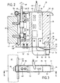
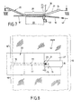
- FIG. 1 shows the application of the device 20 according to the invention in a weaving machine, where a broad web 10 made of warp threads 11 and through Registration of one or more different weft threads as Tissue 12 is generated.
- the warp threads 11 must be woven during the relatively high thread tension already mentioned, which up to 40 g per warp thread 11.
- the warp threads 11 spread to a shed 13 by means of shedding devices, for which so-called shafts 14 are provided in FIG. 1 by their strands the individual warp threads 11 are passed.
- the stems 14 will in the sense of the arrows, according to the weaving pattern, in the Shed 13 moves up and down.
- the warp threads 11 are through a reed 15 pulled, with which the wefts 12 entered in each case the finished tissue can be pressed on.
- the finished fabric 10 is about a breast boom 16 led to a take-off roller 17, the feed of the tissue.
- the Breitbahn fabric is in frictional engagement with the circumference of the take-off roller 17, which absorbs the high thread tension.
- the behind the take-off roller 17 arranged deflection rollers 18 transport the there tissue section 40 with a much lower tension from a maximum of 20 g per warp thread to a fabric tree 19.
- tissue section 40 there is at least one according to the invention Device 20 to be described in more detail.
- the device 20 is attached to a support 41 which extends across the entire width of the fabric 10 runs. Numerous devices 20 sit on the carrier 41, which, according to their number and their distance from each other, the Breitbahn fabric 10 divide into a corresponding group of individual bands 10 '.
- the thread material of the weft threads 12 and / or the warp threads 11 is meltable, d. that is, it can be cut using heat.
- a cutting element 21 provided in the device 20 serves for this purpose in the first embodiment of FIGS. 2 to 8 from a heated wire consists. Belongs to this heated wire 21 in a compact arrangement another pressure member 22, which in the present case consists of a leaf spring 22 exists.
- the leaf spring 22 is, according to FIG. 6, with a gap 24 trained breakthrough, the gap opening 25 for free Leaf end is open. 5 could be the breakthrough of the leaf spring 22 'alternatively from a slot enclosed on all sides by the sheet material 24 'exist.
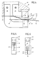
- the leaf spring 22 is opposite with one Blade end 26 stationary on a housing to be described in more detail 50 attached and has an angled free sheet portion 27. This angled sheet section 27 moves in the opposite direction to the transport movement 42 of the broad web 10 from the fabric and therefore acts as a run-up slope.
- the leaf spring 22 is also bent in a Z-shape and rests with a central section 28 on a stationary support member 33, which forms the third element of the device 20 and on the housing 30 is attached.
- the leaf spring 22 is under one because of it Kinks defined the spring tension of their resilient sheet material and presses with its central section 28 the tissue 10 or the tissue cut therefrom Bands 10 'from the top of the fabric against that on the bottom of the fabric arranged support member 33.
- the leaf spring 22 belongs to the breakthrough penetrating wire 21 and finally this leaf spring 22nd assigned support member 33 to a compact unit 30, which on the desired separation point of the Breitbahn 10 is mounted.
- This unit 30 is part of a block 35, which has a plate shape, made of insulation material exists and is part of the housing 50 already mentioned.
- two electrical connections 31 protrude, 32 which here consist of angular metal sheets, one of which is 21 above and the other 32 below the Breitbahn 10 lie.
- the lower plate 32 carries the support member 33, which is a wedge-shaped Has cross-sectional profile.
- Wedge tip 34 of support member 33 is directed downwards to the assembly of the block 35 on the long grain 10, which is done from the top of the web.
- the wedge tip 34 opposite wedge surface 36 is flat, stands with the Underside of the Breitbahn 10 in surface contact and serves as an abutment for the leaf spring 22 supported thereon under spring pressure
- a fastening means sits at the front end face of the wedge-shaped support member 33 37 for the lower end of the wire 21.
- the upper sheet 31 is provided at the end with a thickened head 38, which is also a fastener 39 for the other end of the wire 21.
- An electrical cable 43 is led out at the upper end of the block 35, the electrical supply lines for the heating current of the wire 21st possesses that, which cannot be seen in more detail, in electrical connection stand with the aforementioned angular sheets 31, 32.
- the electrical Cable 43 may also include electrical control lines.
- the electrical Lines of the cable 43 are contacted with electrical components 44, which are arranged inside the block 35 and for heating control of the Serve wire 21.
- the electrical components 44 are expediently Part of an electrical circuit board 45, which is inside the block 35 is integrated.
- function indicators can also sit, which protrude from block 35 and Z. B. the thermal operating state of the wire 21 visible do.
- the function displays 47 in the present case consist of a red and a green glow lamp.
- the block 35 is part of a housing 50, which in the present case simply consists of two flat side plates 51, 52 exists, the distance 53 from each other simply by the plate thickness of the intermediate block 35 is determined.
- Block 35 becomes sandwich-like between the two side plates 51, 52 by fastening screws braced which holes 55 protrude in block 35 and both ends are anchored in the side plates 51, 52.
- the assembly 30 is attached to the already mentioned by means of the housing 50 Carrier 41 attached, the here from a cross across the fabric Support rail 41 is made.
- the mounting rail has to hold the housing 50 41 an upper and a lower profile bar 48, 49.
- the lower profile bar 48 has an edge cross section which is used to guide the housing 50 serves along the mounting rail 41 and in a corresponding angular Cutout 58 at the rear end of the two housing side plates 51, 52 engages.
- the upper profile bar 48 of the mounting rail 41 is in the case of attachment gripped by a snap spring 59, which acts as a holding means of the housing 50 acts.
- the snap spring 59 is, as shown in FIG.
- the insert 54 is also effective on the front end face the upper profile bar 49.
- the insert 54 is also sandwich-like clamped between the two side plates 51, 52, including the plate-shaped Block 35 at its end facing the mounting rail 41 has step-shaped outbreak 57.
- the snap spring 59 reaches behind a rear edge of the upper profile bar 49 and holds the housing 50 under spring tension positively on the mounting rail 41.
- the outbreak 57 of the plate-shaped block 35 is also yet another Insert 56, which acts as a guide on the front end face when installed the lower profile bar 48 is guided.
- This insert too 56 is provided with holes for fastening screws that the insert 56 sandwich between the two side plates 51, 52.
- the snap spring 59 can by a tool, for. B. a screwdriver, from their mounting position engaging behind the upper profile strip 49 Fig. 2 are solved.
- the housing 50 is in the sense of the pivot arrow 65 can be tilted away from the mounting rail 41 in order to remove it from the mounting rail 41 to be able to disassemble.
- the pivot point for this pivoting movement 65 then lies in the area of the described plate cutouts 58 on the lower one Profile bar 48.
- the housing 50 After pivoting away 65, the housing 50 also subtracted from the lower profile bar 48 and thus comfortably from the support rail 41 are removed.
- the assembly of the housing 50 on the mounting rail 41 takes place in the opposite sense.
- actuating means 60 are also provided on the housing 50, the to its longitudinal adjustment in the sense of the double arrow 66 along the Serve rail 41 as shown in FIG. 3. This is required to get the exact one Adjust the width of the strips 10 'to be cut.
- These positioning devices 60 comprise pinions 62, which have toothed racks provided on the mounting rail 41 61 are engaged.
- the racks 61 are on the front End face of the mounting rail 41 between the two profile strips mentioned 48, 49 arranged.
- the adjusting means 60 on the housing side are in the spacing space 63 arranged and located between the two side plates 51, 52 located in the outbreak 57 of the interposed already mentioned several times Blocks 35.
- the pinion 62 sit on a shaft 63, which with their Actuating end 68 protrudes at the upper end of the housing 50 and is pivoted in an upper and lower bearing 64, 67, which is in the mentioned insert pieces 54, 56. Through a turning tool the shaft 63 can be rotated in the direction of the actuating arrow 69 of FIG. 2, which causes the longitudinal adjustment 66 of the housing 50 on the mounting rail 41 is coming.
- the slot 24 allows it, the heatable wire 21 very close to the edge 23 of the slit-shaped To arrange opening 24 of the leaf spring 22.
- the apparent from Fig. 8 Distances 75, 76 between the rear and side edges 23 can are less than 1 mm; 0.75 mm spacing 75 or 76 are sufficient.
- the thread material 11, 12 of the broad web 10 can already be in the temperature range melt between 160 ° and 200 ° C.
- the wire 21 itself can heated to red heat and therefore a temperature of over 400 ° receive.
- a separating cut 70 which the wide fabric 10 in the divides the two bands 10 'shown in FIG. 8.
- the resulting melting edges 77 are from the previously described effective zone 29 the leaf spring 22 is reshaped and smoothed on the support member 33. In the zone 29 effective for pressing, the two melting edges 77 are still plastic.
- the leaf spring heats up indirectly through the strongly heated Wire 21.
- the heat transfer to the leaf spring 22 can convection flow or heat radiation emanating from the heated wire 21 act on the leaf spring 22.
- the angled course mentioned between the center piece and the End piece 27 of the leaf spring 22 favorable.
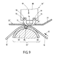
- the cutting member consists of a bow-shaped blade 71.
- the blade 71 has a U-shape, the temple thickness in the region 74 of the temple apex much flatter than in the area of the two ends 72, 73 of the is formed two bow legs. This causes flow of the heating current to a maximum heating in the area 74 of the temple apex.
- the bow-shaped blade 71 passes through with her U-apex region 74 the slot 24 'of the leaf spring already described 22 ', which is used in this device 20' as a pressure member.
- the two electrical connections 78, 79 of this Cutting member 71 on the same side of the wide web 10.
- the leg ends 72, 73 are attached to a slide 80, which in the sense of the push arrow 81 is spring-loaded against the support member 33 'of the device 20'.
- the Slider 80 is in a housing, not shown, of this device 20 'guided in its direction of displacement 81. On this case is the end 25 already described in connection with FIG. 5 the leaf spring 22 'attached.
- This device 20 ' can also be used in a corresponding number arranged on a mounting rail and adjustable in the longitudinal direction of the rail, as described in connection with the device 20 is.
- a difference in the device 20 ' is that all Devices 20 'is assigned a common support member 33'.
- This consists of a multi-layer rod. This includes a central one Cartridge 82, z. B. steel clad is.
- In the jacket 83 there is a longitudinal groove in which a round rod 84 is arranged from ceramic material.
- the round rod 84 serves as an abutment for the blade 71 and, together with the jacket 83, also as a support member for the leaf spring 22 '.
- the ceramic rod 84 forms an edge for deflection of the fabric between the broad web 10 and the cut bands 10 '.
- the devices 20 and in particular 20 'according to the invention need not to be integrated in a loom according to FIG. 1.
- Such an "on-loom” design could also be part of the device a cutting table, where one is previously on a loom or Breitbahn 10 produced on a knitting machine subsequently into individual Bands 10 'to be cut. In this case there is an "off-loom” version in front.
- a heat treatment is used to smooth the fabric after weaving referred to as "heat setting". This heat setting is best done in the area of the take-off roller 17.
- the necessary Means 85 are shown in FIG. 1.
Landscapes
- Engineering & Computer Science (AREA)
- Textile Engineering (AREA)
- Treatment Of Fiber Materials (AREA)
Description
- Fig. 1
- in schematischer Darstellung einen Querschnitt durch eine Webmaschine, wo die besondere Lage der erfindungsgemäßen Vorrichtung verdeutlicht ist,
- Fig. 2,
- in geschnittener Seitenansicht längs der Schnittlinie II-II von Fig. 3 und in Vergrößerung, eine kompakte Vorrichtung nach der Erfindung,
- Fig. 3
- die Draufsicht auf die in Fig. 2 gezeigte Vorrichtung,
- Fig. 4,
- in einer der Fig. 2 entsprechenden Darstellung und in weiterer Vergrößerung, ein Detail der Vorrichtung,
- Fig. 5 und 6
- zwei Varianten eines Bauteils der in Fig. 2 bis 4 bzw. in Fig. 9 gezeigten Vorrichtung,
- Fig. 7
- ein gegenüber Fig. 4 noch größer dargestelltes Detail der dortigen Vorrichtung,
- Fig. 8
- eine längs der Schnittlinie VIII-VIII von Fig. 7 geschnittene Draufsicht auf das in Fig. 7 gezeigte Detail der Vorrichtung, und
- Fig. 9,
- in einer zu Fig. 4 analogen Darstellung, eine alternative Ausbildung der erfindungsgemäßen Vorrichtung.
- 10
- Breitbahn
- 10'
- Band
- 11
- Kettfaden
- 12
- Schußfaden
- 13
- Webfach von 11
- 14
- Schaft für 13
- 15
- Riet für 12
- 16
- Brustbaum
- 17
- Abzugswalze für 10
- 18
- Umlenkwalze für 10'
- 19
- Bandaufrollvorrichtung, Warenbaum
- 20
- erste Vorrichtung (Fig. 1 bis 8)
- 20'
- zweite Vorrichtung (Fig.9)
- 21
- Schneidglied, Draht
- 22, 22'
- Druckglied, Blattfeder
- 23, 23'
- Rand von 22 bzw. 22'
- 24
- Durchbruch, Spalt
- 24'
- Durchbruch, Schlitz
- 25
- Spaltöffnung von 24
- 26
- Befestigungsende von 22 bzw. 22'
- 27
- freies, abgewinkeltes Blattende
- 28
- Mittelabschnitt von 22
- 29
- preßwirksame Zone von 22 bzw. 22' (Fig. 5, 6)
- 30
- Baueinheit
- 31
- Anschluß für 21, winkelförmiges Blech
- 32
- Anschluß für 21, winkelförmiges Blech
- 33, 33'
- Stützglied an 32
- 34
- Keilspitze von 33
- 35
- plattenförmiger Block von 50
- 36
- Keilendfläche von 33
- 37
- Befestigungsmittel für 21 an 33
- 38
- Kopf an 31
- 39
- Befestigungsmittel für 21 an 38
- 40
- Gewebeabschnitt von 10 bzw. 10'
- 41
- Träger für 20, Tragschiene
- 42
- Pfeil der Transportbewegung von 10 bzw. 10'
- 43
- elektrisches Kabel
- 44
- elektrische Bauteile
- 45
- elektrische Leiterplatte für 44
- 46
- Kanal in 35
- 47
- Funktionsanzeigen an 35
- 48
- untere Profilleiste von 41
- 49
- obere Profilleiste von 41
- 50
- Gehäuse
- 51
- erste Seitenplatte von 50
- 52
- zweite Seitenplatte von 50
- 53
- Abstand zwischen 51, 52
- 54
- Einsatzstück für 59
- 55
- Bohrung in 35
- 56
- weiteres Einsatzstück in 53
- 57
- Ausbruch von 35
- 58
- Ausschnitt von 51, 52 für 48
- 59
- Schnappfeder an 50 für 49
- 60
- Stellmittel für 50 längs 41
- 61
- Zahnstange an 41
- 62
- Ritzel von 60
- 63
- Welle von 62
- 64
- oberes Lager von 63 in 54
- 65
- Schwenkbewegungspfeil von 50 (Fig. 2)
- 66
- Längsverstellung von 50 (Fig. 3)
- 67
- unteres Lager von 63 in 56
- 68
- Betätigungsende von 63
- 69
- Betätigungspfeil von 63
- 70
- Trennschnitt zwischen 10' (Fig. 8)
- 71
- bügelförmige Klinge (Fig. 9)
- 72
- erster Schenkel von 71
- 73
- zweiter Schenkel von 71
- 74
- Scheitelbereich von 71
- 75
- hinterer Abstand zwischen 21, 23
- 76
- seitlicher Abstand zwischen 21. 23
- 77
- Schmelzkante von 10' (Fig. 8)
- 78
- elektrischer Anschluß für 72
- 79
- elektrischer Anschluß für 73
- 80
- Schieber für 71 (Fig. 9)
- 81
- Schubpfeil von 80
- 82
- Heizpatrone von 33'
- 83
- Mantel von 82
- 84
- Rundstab in 83
- 85
- Mittel für Thermofixierung bei 17 (Fig. 1)
Claims (17)
- Vorrichtung zum Herstellen von vorzugsweise gemusterten textilen Bändern (10'), insbesondere von Etikettbändern, aus einer schmelzfähiges Material aufweisenden Breitbahn (10), die vorzugsweise aus einem schmelzfähiges Fadenmaterial (11, 12) aufweisenden Gewebe oder Gewirke besteht,dadurch gekennzeichnet,mit einer Schar von ruhenden beheizten Schneidgliedern (21), welche die Breitbahn (10) durchsetzen,wobei die Breitbahn (10) entlang der ruhenden Schneidglieder (21) transportiert (42) wird und dadurch Trennschnitte (70) in der Breitbahn (10) entstehen, welche parallel nebeneinanderliegende Bänder (10') erzeugen,und mit einer Schar von Druckgliedern (22) auf der Oberseite der Breitbahn (10),welche die geschnittenen Bänder (10') im Kantenbereich jeweils gegen ein ortsfestes Widerlager auf der Rückseite der Breitbahn (10) pressen und dadurch die rauhen Schmelzkanten (77) der Bänder (10') glätten,daß das Widerlager aus einer Schar von Stützgliedern (33) auf der Rückseite der Breitbahn (10) besteht und jedem Stützglied (33) nicht nur ein Schneidglied (21), sondern auch ein als Federglied (22) ausgebildetes Druckglied zur Glättung der beiden Schmelzkanten (77) beidseitig des vom jeweiligen Schneidglieds (21) erzeugten Trennschnitts (70) zugeordnet sind,wobei das Federglied (22) zwar selbst nicht beheizt ist, aber so nahe an das beheizte Schneidglied (21) heranreicht, daß es noch auf die plastifizierten Schmelzkanten (77) der Bänder (10') wirkt,und daß dieses an jedem Trennschnitt (70) befindliche Tripel aus einem Schneidglied (21), einem Druckglied (22) und einem Stützglied (33) an einem ihnen zugeordneten einzelnen Block (35) fest montiert ist und das Tripel mit dem Block (35) jeweils eine kompakte, gemeinsam bewegliche Baueinheit bildet,und daß die den einzelnen Trennschnitten (70) zugeordneten Blöcke (35) an einem die Breitbahn (10) überquerenden, ortsfesten Träger (41) sitzen und zwecks Einstellung der jeweils gewünschten Breite der zu schneidenden Bänder individuell entlang des Trägers (41) verstellbar sind.
- Vorrichtung nach Anspruch 1, dadurch gekennzeichnet, daß das Federglied eine Blattfeder (22, 22') ist, die einen Durchbruch (24, 24') aufweist,
daß das Schneidglied (21) den Durchbruch (24, 24') durchsetzt und der Rand (23, 23') des Durchbruchs (24, 24') eine preßwirksame Zone (29) der Blattfeder (22, 22') begrenzt. - Vorrichtung nach Anspruch 1, dadurch gekennzeichnet, daß die freie Lücke (75, 76) zwischen der schmelzwirksamen Stelle des Schneidglieds (21) einerseits und der preßwirksamen Zone (29) der Blattfeder (22, 22') andererseits kleiner als 3 mm ausgebildet ist und vorzugsweise weniger als 1 mm beträgt.
- Vorrichtung nach Anspruch 2 oder 3, dadurch gekennzeichnet, daß der Durchbruch in der Blattfeder (22') aus einem Schlitz (24') besteht, der das hindurchragende Schneidglied (21; 71) allseitig umschließt.
- Vorrichtung nach Anspruch 2 oder 3, dadurch gekennzeichnet, daß der Durchbruch aus einem einseitig offenen Spalt (24) in der Blattfeder (22) besteht, dessen Spaltöffnung (25) zu dem noch unzerschnittenen Abschnitt der Breitbahn (10) hin gerichtet ist.
- Vorrichtung nach einem oder mehreren der Ansprüche 2 bis 5, dadurch gekennzeichnet, daß die Blattfeder (22, 22') zu dem noch unzerschnittenen Bereich der Breitbahn (10) hin abgewinkelt ist und die Abwinkelung (27) sich in Richtung des Blattfeder-Endes zunehmend von der Breitbahn (10) entfernt.
- Vorrichtung nach einem oder mehreren der Ansprüche 1 bis 6, dadurch gekennzeichnet, daß das Schneidglied aus einem beheizten Draht (21) besteht, dessen Drahtenden auf zueinander gegenüberliegenden Seiten der zu zerschneidenden Breitbahn (10) liegen.
- Vorrichtung nach einem oder mehreren der Ansprüche 1 bis 5, dadurch gekennzeichnet, daß das Schneidglied aus einer bügelförmigen Klinge (71) besteht, deren Bügelscheitel-Bereich (74) zwar den Durchbruch (24') der Blattfeder durchragt, dessen beide Bügelenden (72, 73) aber auf der gleichen Seite der Breitbahn (10) liegen.
- Vorrichtung nach Anspruch 1 bis 8, dadurch gekennzeichnet, daß wenigstens einige elektrische Bauteile (44), die zur Heizsteuerung des Schneidglieds (21) dienen, in den jeweiligen Block (35) integriert sind.
- Vorrichtung nach Anspruch 1 bis 9, dadurch gekennzeichnet, daß am Block (35) Funktionsanzeigen (47) für den thermischen und/oder mechanischen Betriebszustand des zugehörigen Schneidglieds (21) integriert sind.
- Vorrichtung nach einem oder mehreren der Ansprüche 1 bis 12, dadurch gekennzeichnet, daß der Block (35) Plattenform aufweist und Bestandteil eines aus zwei voneinander beabstandeten Seitenplatten (51, 52) bestehenden Gehäuses (50) ist,daß der Block (35) aus Isolationsmaterial besteht und im Abstandsraum (53) zwischen den beiden Seitenplatten (51, 52) des Gehäuses (50) befestigt ist,wobei der Block (35) elektrische Anschlüsse für das Schneidglied (21) besitzt und ggf. die elektrischen Bauteile (44) zur Heizsteuerung des Schneidglieds (21) beinhaltet,und daß das Gehäuse (50) die Haltemittel (58, 59) zur Anbringung des Blocks (35) an dem Träger (41) und ggf. die Stellmittel (60) zur Längsverstellung (41) des Blocks (35) am Träger (41) trägt.
- Vorrichtung nach Anspruch 11, dadurch gekennzeichnet, daß die Haltemittel (59) und ggf. die Stellmittel (60) im Abstandsraum (53) zwischen den beiden Seitenplatten (51, 52) des Gehäuses (50) angeordnet sind.
- Vorrichtung nach einem oder mehreren der Ansprüche 1 bis 12, dadurch gekennzeichnet, daß der Block (35) in eine Webmaschine integriert ist, auf welcher die Breitbahn (10) gewebt wird.
- Vorrichtung nach einem oder mehreren der Ansprüche 1 bis 12, dadurch gekennzeichnet, daß der Block (35) Bestandteil eines Schneidtisches ist, der eine anderweitig hergestellte Breitbahn (10) nachträglich in einzelne Bänder (10') zu zerschneiden gestattet.
- Vorrichtung insbesondere nach Anspruch 14 mit einer Abzugswalze (17), welche die Schußfadendichte des Gewebes in der Webmaschine bestimmt, dadurch gekennzeichnet, daß die Kombination aus dem Schneidglied (21) und der Blattfeder (22) bzw. die Baueinheit (30) aus dem Schneidglied (21), der Blattfeder (22) und dem Stützglied (33) bzw. der die Baueinheit aufweisende Block (35) - in Transportrichtung (42) des Breitbahn Gewebes (10) auf der Webmaschine gesehen - in einem hinter der Abzugswalze (17) liegenden Gewebeabschnitt (40) angeordnet ist, der nicht mehr unter der für das Weben erforderlichen hohen Gewebespannung steht.
- Vorrichtung nach Anspruch 15, dadurch gekennzeichnet, daß eine zusätzliche Wärmebehandlung zur sogenannten Fixierung des Gewebes (10) an dem noch unzerschnittenen Breitbahngewebe (10) im Bereich der Abzugswalze (17) erfolgt.
- Vorrichtung nach Anspruch 15, dadurch gekennzeichnet, daß eine Einrichtung zur zusätzliche Wärmebehandlung und Fixierung des Gewebes hinter der Abzugswalze (17) der Webmaschine angeordnet ist und ggf. an den bereits geschnittenen Bändern (10') des Gewebes erfolgt.
Applications Claiming Priority (5)
| Application Number | Priority Date | Filing Date | Title |
|---|---|---|---|
| DE19536963A DE19536963A1 (de) | 1995-10-04 | 1995-10-04 | Vorrichtung zum Herstellen gemusterter textiler Bänder, insbesondere Etikettbänder, aus einer Breitbahn |
| DE19536963 | 1995-10-04 | ||
| DE19604735A DE19604735A1 (de) | 1995-10-04 | 1996-02-09 | Vorrichtung zum Herstellen gemusterter textiler Bänder, insbesondere Etikettbänder, aus einer Breitbahn |
| DE19604735 | 1996-02-09 | ||
| PCT/EP1996/004244 WO1997013023A1 (de) | 1995-10-04 | 1996-09-28 | Vorrichtung zum herstellen von vorzugsweise gemusterten textilen bändern, insbesondere von etikettbändern, aus einer schmelzfähiges material aufweisenden breitbahn |
Publications (2)
| Publication Number | Publication Date |
|---|---|
| EP0853697A1 EP0853697A1 (de) | 1998-07-22 |
| EP0853697B1 true EP0853697B1 (de) | 1999-10-20 |
Family
ID=26019236
Family Applications (1)
| Application Number | Title | Priority Date | Filing Date |
|---|---|---|---|
| EP96933419A Expired - Lifetime EP0853697B1 (de) | 1995-10-04 | 1996-09-28 | Vorrichtung zum herstellen von vorzugsweise gemusterten textilen bändern, insbesondere von etikettbändern, aus einer schmelzfähiges material aufweisenden breitbahn |
Country Status (2)
| Country | Link |
|---|---|
| EP (1) | EP0853697B1 (de) |
| WO (1) | WO1997013023A1 (de) |
Cited By (1)
| Publication number | Priority date | Publication date | Assignee | Title |
|---|---|---|---|---|
| DE102006061140A1 (de) * | 2006-12-22 | 2008-06-26 | Vaupel Textilmaschinen Gmbh & Co. Kg | Vorrichtung zum thermischen Schneiden einer aus schmelzfähigem Fadenmaterial bestehenden Textilbahn in Bänder |
Families Citing this family (5)
| Publication number | Priority date | Publication date | Assignee | Title |
|---|---|---|---|---|
| DE19644534C2 (de) | 1996-10-26 | 2001-03-22 | Vaupel Textilmaschinen Gmbh & | Vorrichtung zum Längstrennen einer schmelzfähigen Breitbahn in mindestens zwei Bändern, insbesondere in gemusterte Etikettbänder |
| CH697695B1 (de) * | 2003-02-06 | 2009-01-15 | Textilma Ag | Schneidvorrichtung zum thermischen Schneiden einer laufenden, insbesondere gemusterten Textilbahn. |
| DE102006020950A1 (de) * | 2006-05-05 | 2008-01-31 | Vaupel Textilmaschinen Gmbh & Co. Kg | Vorrichtung zum thermischen Schneiden einer aus schmelzfähigem Fadenmaterial bestehenden Textilbahn in Bänder |
| WO2009061310A1 (en) * | 2007-11-05 | 2009-05-14 | Yidi Carlos Jr | Device for thermal cutting of a fabric sheet into ribbons |
| EP3722471A1 (de) | 2019-04-10 | 2020-10-14 | Textilma AG | Verfahren zum herstellen von kaltgeschnittenen gewebebahnen |
Family Cites Families (4)
| Publication number | Priority date | Publication date | Assignee | Title |
|---|---|---|---|---|
| DE2307096A1 (de) * | 1973-02-14 | 1974-08-22 | Ver Seidenwebereien Ag | Gleitende distanzhalterung |
| DE2516057A1 (de) * | 1975-04-12 | 1976-10-28 | Mageba Textilmaschinen Gmbh | Eine der abzugseinrichtung eines webstuhles nachgeordnete schneidvorrichtung |
| DE4011293A1 (de) * | 1989-04-12 | 1990-10-18 | Loepfe Ag Geb | Vorrichtung zum thermischen trennen von textilen flaechengebilden |
| ES2096087T3 (es) * | 1991-07-18 | 1997-03-01 | Textilma Ag | Procedimiento y maquina tejedora para la fabricacion de un carril cortado termicamente. |
-
1996
- 1996-09-28 EP EP96933419A patent/EP0853697B1/de not_active Expired - Lifetime
- 1996-09-28 WO PCT/EP1996/004244 patent/WO1997013023A1/de not_active Ceased
Cited By (1)
| Publication number | Priority date | Publication date | Assignee | Title |
|---|---|---|---|---|
| DE102006061140A1 (de) * | 2006-12-22 | 2008-06-26 | Vaupel Textilmaschinen Gmbh & Co. Kg | Vorrichtung zum thermischen Schneiden einer aus schmelzfähigem Fadenmaterial bestehenden Textilbahn in Bänder |
Also Published As
| Publication number | Publication date |
|---|---|
| EP0853697A1 (de) | 1998-07-22 |
| WO1997013023A1 (de) | 1997-04-10 |
Similar Documents
| Publication | Publication Date | Title |
|---|---|---|
| DE3937947C2 (de) | ||
| EP0389793A2 (de) | Verfahren und Vorrichtung zur Herstellung einer Schar paralleler, insbesondere gemusterter, Etikettbänder | |
| DE3140480A1 (de) | "kettenwirkmaschine mit einem schussfadenmagazin und einer vlies-zufuehrvorrichtung" | |
| WO1989002491A1 (fr) | Metier a tisser | |
| EP0934437B1 (de) | Vorrichtung zum trennen einer schmelzfähigen breitbahn in mindestens zwei bänder, insbesondere in gemusterte etikettbänder | |
| DE2302949C2 (de) | Webmaschine zur Herstellung von Bändern | |
| EP0853697B1 (de) | Vorrichtung zum herstellen von vorzugsweise gemusterten textilen bändern, insbesondere von etikettbändern, aus einer schmelzfähiges material aufweisenden breitbahn | |
| DE9102325U1 (de) | Doppelpunktschweißmaschine | |
| DE2931167C2 (de) | Vorrichtung zum kompressiven Schrumpfen einer textilen Warenbahn | |
| DE69401439T2 (de) | Vorrichtung zum niederhalten der maschen an einer flachstrickmaschine | |
| DE3851532T2 (de) | Infrarot-wärmestrahler mit reflektor und belüfteter struktur. | |
| DE3815395A1 (de) | Webmaschine | |
| DE3128011A1 (de) | Verbindung zwischen laengenabschnitten von metallstreifen und vorrichtung zum herstellen dieser verbindungen | |
| DE68917342T2 (de) | Werkzeuge mit Einsatzzähnen. | |
| CH695345A5 (de) | Musterlegebarrenanordnung für Kettenwirkmaschinen. | |
| DE3443914A1 (de) | Maschine mit einer zum bilden von schweissnaehten in einer thermoplastischen folie dienenden schweissleiste | |
| DE102007036503B3 (de) | Vorrichtung zum Weben eines Breitgewebes und zum Trennen des Breitgewebes in Bänder | |
| EP1525960A1 (de) | Schneidvorrichtung zum Schneiden einer Materialbahn | |
| EP0705925A2 (de) | Heizeinrichtung mit auswechselbaren Fadenführern | |
| DE4115800A1 (de) | Verfahren und vorrichtung zur herstellung eines durch figurschuss gemusterten textilen bandes, insbesondere eines etikettbandes, aus einer breitbahn mit schmelzfaehigem fadenwerkstoff | |
| DE19536963A1 (de) | Vorrichtung zum Herstellen gemusterter textiler Bänder, insbesondere Etikettbänder, aus einer Breitbahn | |
| DE10011570A1 (de) | Vorrichtung zum Herstellen von vorzugsweise gemusterten textilen Bändern aus einer schmelzfähiges Material aufweisenden Breitbahn | |
| EP0546485A1 (de) | Verfahren zum Herstellen eines durch Figurschüsse gemusterten textilen Bandes, insbesondere eines Etikettbandes | |
| DE1941438A1 (de) | Schneidvorrichtung | |
| WO1991003592A1 (de) | Vorrichtung zum thermischen schneiden einer laufenden materialbahn aus thermoplastischem material |
Legal Events
| Date | Code | Title | Description |
|---|---|---|---|
| PUAI | Public reference made under article 153(3) epc to a published international application that has entered the european phase |
Free format text: ORIGINAL CODE: 0009012 |
|
| 17P | Request for examination filed |
Effective date: 19980227 |
|
| AK | Designated contracting states |
Kind code of ref document: A1 Designated state(s): DE |
|
| GRAG | Despatch of communication of intention to grant |
Free format text: ORIGINAL CODE: EPIDOS AGRA |
|
| 17Q | First examination report despatched |
Effective date: 19990114 |
|
| GRAG | Despatch of communication of intention to grant |
Free format text: ORIGINAL CODE: EPIDOS AGRA |
|
| GRAH | Despatch of communication of intention to grant a patent |
Free format text: ORIGINAL CODE: EPIDOS IGRA |
|
| GRAH | Despatch of communication of intention to grant a patent |
Free format text: ORIGINAL CODE: EPIDOS IGRA |
|
| GRAA | (expected) grant |
Free format text: ORIGINAL CODE: 0009210 |
|
| AK | Designated contracting states |
Kind code of ref document: B1 Designated state(s): DE |
|
| REF | Corresponds to: |
Ref document number: 59603438 Country of ref document: DE Date of ref document: 19991125 |
|
| PLBE | No opposition filed within time limit |
Free format text: ORIGINAL CODE: 0009261 |
|
| STAA | Information on the status of an ep patent application or granted ep patent |
Free format text: STATUS: NO OPPOSITION FILED WITHIN TIME LIMIT |
|
| 26N | No opposition filed | ||
| PGFP | Annual fee paid to national office [announced via postgrant information from national office to epo] |
Ref country code: DE Payment date: 20021024 Year of fee payment: 7 |
|
| PG25 | Lapsed in a contracting state [announced via postgrant information from national office to epo] |
Ref country code: DE Free format text: LAPSE BECAUSE OF NON-PAYMENT OF DUE FEES Effective date: 20040401 |