EP0838732A1 - Arbeitseinheit und elektrophotographisches Bilderzeugungsgerät - Google Patents
Arbeitseinheit und elektrophotographisches Bilderzeugungsgerät Download PDFInfo
- Publication number
- EP0838732A1 EP0838732A1 EP97307588A EP97307588A EP0838732A1 EP 0838732 A1 EP0838732 A1 EP 0838732A1 EP 97307588 A EP97307588 A EP 97307588A EP 97307588 A EP97307588 A EP 97307588A EP 0838732 A1 EP0838732 A1 EP 0838732A1
- Authority
- EP
- European Patent Office
- Prior art keywords
- process cartridge
- photosensitive drum
- projection
- main assembly
- hole
- Prior art date
- Legal status (The legal status is an assumption and is not a legal conclusion. Google has not performed a legal analysis and makes no representation as to the accuracy of the status listed.)
- Granted
Links
Images


Classifications
-
- G—PHYSICS
- G03—PHOTOGRAPHY; CINEMATOGRAPHY; ANALOGOUS TECHNIQUES USING WAVES OTHER THAN OPTICAL WAVES; ELECTROGRAPHY; HOLOGRAPHY
- G03G—ELECTROGRAPHY; ELECTROPHOTOGRAPHY; MAGNETOGRAPHY
- G03G21/00—Arrangements not provided for by groups G03G13/00 - G03G19/00, e.g. cleaning, elimination of residual charge
- G03G21/16—Mechanical means for facilitating the maintenance of the apparatus, e.g. modular arrangements
- G03G21/18—Mechanical means for facilitating the maintenance of the apparatus, e.g. modular arrangements using a processing cartridge, whereby the process cartridge comprises at least two image processing means in a single unit
- G03G21/1839—Means for handling the process cartridge in the apparatus body
- G03G21/1857—Means for handling the process cartridge in the apparatus body for transmitting mechanical drive power to the process cartridge, drive mechanisms, gears, couplings, braking mechanisms
- G03G21/186—Axial couplings
-
- F—MECHANICAL ENGINEERING; LIGHTING; HEATING; WEAPONS; BLASTING
- F16—ENGINEERING ELEMENTS AND UNITS; GENERAL MEASURES FOR PRODUCING AND MAINTAINING EFFECTIVE FUNCTIONING OF MACHINES OR INSTALLATIONS; THERMAL INSULATION IN GENERAL
- F16D—COUPLINGS FOR TRANSMITTING ROTATION; CLUTCHES; BRAKES
- F16D1/00—Couplings for rigidly connecting two coaxial shafts or other movable machine elements
- F16D1/10—Quick-acting couplings in which the parts are connected by simply bringing them together axially
- F16D1/101—Quick-acting couplings in which the parts are connected by simply bringing them together axially without axial retaining means rotating with the coupling
-
- G—PHYSICS
- G03—PHOTOGRAPHY; CINEMATOGRAPHY; ANALOGOUS TECHNIQUES USING WAVES OTHER THAN OPTICAL WAVES; ELECTROGRAPHY; HOLOGRAPHY
- G03G—ELECTROGRAPHY; ELECTROPHOTOGRAPHY; MAGNETOGRAPHY
- G03G15/00—Apparatus for electrographic processes using a charge pattern
- G03G15/75—Details relating to xerographic drum, band or plate, e.g. replacing, testing
- G03G15/757—Drive mechanisms for photosensitive medium, e.g. gears
-
- G—PHYSICS
- G03—PHOTOGRAPHY; CINEMATOGRAPHY; ANALOGOUS TECHNIQUES USING WAVES OTHER THAN OPTICAL WAVES; ELECTROGRAPHY; HOLOGRAPHY
- G03G—ELECTROGRAPHY; ELECTROPHOTOGRAPHY; MAGNETOGRAPHY
- G03G21/00—Arrangements not provided for by groups G03G13/00 - G03G19/00, e.g. cleaning, elimination of residual charge
- G03G21/16—Mechanical means for facilitating the maintenance of the apparatus, e.g. modular arrangements
- G03G21/1604—Arrangement or disposition of the entire apparatus
- G03G21/1623—Means to access the interior of the apparatus
- G03G21/1633—Means to access the interior of the apparatus using doors or covers
-
- G—PHYSICS
- G03—PHOTOGRAPHY; CINEMATOGRAPHY; ANALOGOUS TECHNIQUES USING WAVES OTHER THAN OPTICAL WAVES; ELECTROGRAPHY; HOLOGRAPHY
- G03G—ELECTROGRAPHY; ELECTROPHOTOGRAPHY; MAGNETOGRAPHY
- G03G21/00—Arrangements not provided for by groups G03G13/00 - G03G19/00, e.g. cleaning, elimination of residual charge
- G03G21/16—Mechanical means for facilitating the maintenance of the apparatus, e.g. modular arrangements
- G03G21/1642—Mechanical means for facilitating the maintenance of the apparatus, e.g. modular arrangements for connecting the different parts of the apparatus
- G03G21/1647—Mechanical connection means
-
- F—MECHANICAL ENGINEERING; LIGHTING; HEATING; WEAPONS; BLASTING
- F16—ENGINEERING ELEMENTS AND UNITS; GENERAL MEASURES FOR PRODUCING AND MAINTAINING EFFECTIVE FUNCTIONING OF MACHINES OR INSTALLATIONS; THERMAL INSULATION IN GENERAL
- F16D—COUPLINGS FOR TRANSMITTING ROTATION; CLUTCHES; BRAKES
- F16D1/00—Couplings for rigidly connecting two coaxial shafts or other movable machine elements
- F16D1/10—Quick-acting couplings in which the parts are connected by simply bringing them together axially
- F16D2001/102—Quick-acting couplings in which the parts are connected by simply bringing them together axially the torque is transmitted via polygon shaped connections
-
- G—PHYSICS
- G03—PHOTOGRAPHY; CINEMATOGRAPHY; ANALOGOUS TECHNIQUES USING WAVES OTHER THAN OPTICAL WAVES; ELECTROGRAPHY; HOLOGRAPHY
- G03G—ELECTROGRAPHY; ELECTROPHOTOGRAPHY; MAGNETOGRAPHY
- G03G2221/00—Processes not provided for by group G03G2215/00, e.g. cleaning or residual charge elimination
- G03G2221/16—Mechanical means for facilitating the maintenance of the apparatus, e.g. modular arrangements and complete machine concepts
- G03G2221/1651—Mechanical means for facilitating the maintenance of the apparatus, e.g. modular arrangements and complete machine concepts for connecting the different parts
- G03G2221/1654—Locks and means for positioning or alignment
-
- G—PHYSICS
- G03—PHOTOGRAPHY; CINEMATOGRAPHY; ANALOGOUS TECHNIQUES USING WAVES OTHER THAN OPTICAL WAVES; ELECTROGRAPHY; HOLOGRAPHY
- G03G—ELECTROGRAPHY; ELECTROPHOTOGRAPHY; MAGNETOGRAPHY
- G03G2221/00—Processes not provided for by group G03G2215/00, e.g. cleaning or residual charge elimination
- G03G2221/16—Mechanical means for facilitating the maintenance of the apparatus, e.g. modular arrangements and complete machine concepts
- G03G2221/1651—Mechanical means for facilitating the maintenance of the apparatus, e.g. modular arrangements and complete machine concepts for connecting the different parts
- G03G2221/1657—Mechanical means for facilitating the maintenance of the apparatus, e.g. modular arrangements and complete machine concepts for connecting the different parts transmitting mechanical drive power
Definitions
- the present invention relates to a process cartridge and an electrophotographic image forming apparatus.
- the electrophotographic image forming apparatus forms an image on a recording material using an electrophotographic image formation process.
- the electrophotographic image forming apparatus includes an electrophotographic copying machine, an electrophotographic printer (laser beam printer, LED printer or the like), a facsimile machine and a word processor or the like.
- the process cartridge contains integrally electrophotographic photosensitive member and charging means, developing means or cleaning means, and is detachably mountable relative to a main assembly of the image forming apparatus. It may integrally contain the electrophotographic photosensitive member and at least one of the charging means, the developing means and the cleaning means. As another example, it may contain the electrophotographic photosensitive member and at least the developing means.
- the process cartridge which contains the electrophotographic photosensitive member and process means actable on said electrophotographic photosensitive member, and which is detachably mountable as a unit to a main assembly of the image forming apparatus (process cartridge type).
- process cartridge type the maintenance of the apparatus can be carried out in effect by the user without depending on a serviceman. Therefore, the process cartridge type is now widely used in electrophotographic image forming apparatuses.
- the present invention is directed to a further improvement of such a process cartridge.
- a driving system for a photosensitive member in a process cartridge type is disclosed in U.S. Patent Nos. 4,829,335 and 5,023,660.
- Figure 1 is a vertical section of an electrophotographic image forming apparatus.
- Figure 2 is an external perspective view of the apparatus illustrated in Figure 1.
- Figure 3 is a cross-section of a process cartridge.
- Figure 4 is an external perspective view of the process cartridge illustrated in Figure 3, as seen from the top right direction.
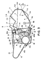
- Figure 5 is the right-hand side view of the process cartridge illustrated in Figure 3.
- Figure 6 is the left-hand side view of the process cartridge illustrated in Figure 3.
- Figure 7 is an external perspective view of the process cartridge illustrated in Figure 3, as seen from the top left direction.
- Figure 8 is an external perspective view of the bottom left side of the process cartridge illustrated in Figure 3.
- Figure 9 is an external perspective view of the process cartridge accommodating portion of the main assembly of the apparatus illustrated in Figure 1.
- Figure 10 is an external perspective view of the process cartridge accommodating portion of the main assembly of the apparatus illustrated in Figure 1.
- Figure 11 is a vertical section of a photosensitive drum and a driving mechanism for driving the photosensitive drum.
- Figure 12 is a perspective view of a cleaning unit.
- Figure 13 is a perspective view of an image developing unit.
- Figure 14 is a perspective view of a drum flange (driving force transmitting part) according to a first embodiment.
- Figure 15 is a perspective view of a photosensitive drum according to Embodiment 1 of the present invention.
- Figure 16 is a perspective view of a side shaft coupling portion of a process cartridge according to Embodiment 1 of the present invention.
- Figure 17 is a perspective view of a shaft coupling used in the process cartridge and the main assembly of the electrophotographic image forming apparatus according to Embodiment 1 of the present invention.
- Figure 18 is a cross-sectional view of a driving system provided in the main assembly of the electrophotographic image forming apparatus according to Embodiment 1 of the present invention.
- Figure 19 is a perspective view of a shaft coupling member provided in the process cartridge and the shaft coupling member provided in the main assembly of the apparatus according to Embodiment 1 of the present invention.
- Figure 20 is a perspective view of a coupling provided in the process cartridge and a shaft coupling member provided in the main assembly of the apparatus according to Embodiment 1 of the present invention.
- Figure 21 is a longitudinal sectional view of a coupling portion and a cover of the main assembly of the apparatus according to Embodiment 1 of the present invention.
- Figure 22 is a side view of a structure of a female coupling shaft according to an embodiment of the present invention.
- Figure 23 is a side view showing the structure around the female coupling shaft when the mounting-and-demounting of the process cartridge is mounted to or demounted from the main assembly of the apparatus according to Embodiment 1 of the present invention.
- Figure 24 (a), (b) is a sectional view taken along a plane perpendicular to the axis of the male coupling projection and recess according to Embodiment 1 of the present invention.
- Figure 25 is a perspective view of a coupling projection and a coupling recess according to a further embodiment of the present invention.
- Figure 26 is a perspective view of a leaf spring provided in a main assembly of an apparatus.
- Figure 27 is a side view of a leaf spring provided in a main assembly of an apparatus.
- Figure 28 is a perspective view of a leaf spring provided in a process cartridge.
- Figure 29 is a side view of a leaf spring provided in a process cartridge.
- the "widthwise" direction of a process cartridge B means the direction in which the process cartridge B is installed into, or removed from, the main assembly of an image forming apparatus, and coincides with the direction in which a recording medium is conveyed.
- the "lengthwise” direction of the process cartridge B means a direction which is intersectional with (substantially perpendicular to) the direction in which the process cartridge B is installed into, or removed from, the main assembly 14. It is parallel to the surface of the recording medium, and intersectional with (substantially perpendicular to) the direction in which the recording medium is conveyed.
- the "left” or “right” means the left or right relative to the direction in which the recording medium is conveyed, as seen from above.
- Figure 1 is an electrophotographic image forming apparatus (laser beam printer) which embodies the present invention, depicting the general structure thereof;
- Figures 3 - 8 are drawings of process cartridges which embody the present invention. More specifically, Figure 3 is a cross-section of a process cartridge; Figure 4, an external perspective view of the process cartridge; Figure 5, a right-hand side view of the process cartridge; Figure 6, a left-hand side view of the process cartridge; Figure 7, a perspective view of the process cartridge as seen from the top left direction; and Figure 8 is a perspective view of the process cartridge as seen from the bottom left direction.
- the "top" surface of the process cartridge B means the surface which faces upward when the process cartridge B is in the main assembly 14 of the image forming apparatus, and the "bottom” surface means the surface which faces downward.
- FIG. 1 a laser beam printer A as an electrophotographic image forming apparatus which embodies the present invention will be described.
- Figure 3 is a cross-section of a process cartridge which also embodies the present invention.
- the laser beam printer A is an apparatus which forms an image on a recording medium (for example, recording sheet, OHP sheet, and fabric) through an electrophotographic image forming process. It forms a toner image on an electrophotographic photosensitive drum (hereinafter, photosensitive drum) in the form of a drum. More specifically, the photosensitive drum is charged with the use of a charging means, and a laser beam modulated with the image data of a target image is projected from an optical means onto the charged peripheral surface of the photosensitive drum, forming thereon a latent image in accordance with the image data. This latent image is developed into a toner image by a developing means.
- a recording medium for example, recording sheet, OHP sheet, and fabric
- photosensitive drum electrophotographic photosensitive drum
- a recording medium 2 placed in a sheet feeding cassette 3a is reversed and conveyed by a pickup roller 3b, a conveyer roller pairs 3c and 3d, and register roller pair 3e, in synchronism with the toner formation.
- voltage is applied to an image transferring roller 4 as a means for transferring the toner image formed on the photosensitive drum 7 of the process cartridge B, whereby the toner image is transferred onto the recording medium 2.
- the recording medium 2, onto which the toner image has been transferred is conveyed to a fixing means 5 by guiding conveyer 3f.
- the fixing means 5 has a driving roller 5c, and a fixing roller 5b containing a heater 5a, and applies heat and pressure to the recording medium 2 as the recording medium 2 is passed through the fixing means 5, so that the image having been transferred onto the recording medium 2 is fixed to the recording medium 2. Then, the recording medium 2 is conveyed farther, and is discharged into a delivery tray 6 through a reversing path 3j, by discharging roller pairs 3q, 3h and 3i.
- the delivery tray 6 is located at the top of the main assembly 14 of the image forming apparatus A.
- a pivotable flapper 3k may be operated in coordination with a discharge roller pair 2m to discharge the recording medium 2 without passing it through the reversing path 3j.
- the pickup roller 3b, conveyer roller pairs 3c and 3d, register roller pair 3e, guiding conveyer 3f, discharge roller pairs 3g, 3h and 3i, and discharge roller pair 3m constitute a conveying means 3.
- the photosensitive drum 7 with a photosensitive layer 7e ( Figure 11) is rotated to uniformly charge its surface by applying voltage to the charging roller 8 as a photosensitive drum charging means. Then, a laser beam modulated with the image data is projected onto the photosensitive drum 7 from the optical system 1 through an exposure opening le, forming a latent image on the photosensitive drum 7. The thus formed latent image is developed with the use of toner and the developing means 9. More specifically, the charging roller 8 is disposed in contact with the photosensitive drum 7 to charge the photosensitive drum 7. It is rotated by the rotation of the photosensitive drum 7.
- the developing means 9 provides the peripheral surface area (area to be developed) of the photosensitive drum 7 with toner so that the latent image formed on the photosensitive drum 7 is developed.
- the optical system 1 comprises a laser diode la, a polygon mirror 1b, a lens 1c, and a deflective mirror 1d.
- the toner contained in a toner container 11A is delivered to an developing roller 9c by the rotation of a toner feeding member 9b.
- the developing roller 9c contains a stationary magnet. It is also rotated so that a layer of toner with triboelectric charge is formed on the peripheral surface of the developing roller 9c.
- the image developing area of the photosensitive drum 7 is provided with the toner from this toner layer, the toner is transferred onto the peripheral surface of the photosensitive drum 7 in a manner to reflect the latent image, visualizing the latent image as a toner image.
- the developing blade 9d is a blade which regulates the amount of the toner adhered to the peripheral surface of the developing roller 9c and also triboelectrically charges the toner.
- Adjacent to the developing roller 9c, a toner stirring member 9c is rotatively disposed to circulatively stir the toner within the image developing chamber.
- the cleaning means 10 comprises an elastic cleaning blade 10a disposed in contact with the photosensitive drum 7, and the toner remaining on the photosensitive drum 7 is scraped off by the elastic cleaning blade 10a, being collected into a waste toner collector 10b.
- the process cartridge B is formed in the following manner. First, a toner chamber frame 11 which comprises a toner container (toner storing portion) llA for storing toner is joined with an image developing chamber frame 12 which houses the image developing means 9 such as an image developing roller 9c, and then, a cleaning chamber frame 13, in which the photosensitive drum 7, the cleaning means 10 such as the cleaning blade 10a, and the charging roller 8 are mounted, is joined with the preceding two frames 11 and 12 to complete the process cartridge B.
- the thus formed process cartridge B is removably installable into the main assembly 14 of the image forming apparatus A.
- the process cartridge B is provided with an exposure opening is through which a light beam modulated with image data is projected onto the photosensitive drum 7, and a transfer opening 13n through which the photosensitive drum 7 opposes the recording medium 2.
- the exposure opening le is a part of the cleaning chamber frame 11, and the transfer opening 13n is located between the image developing chamber frame 12 and the cleaning chamber frame 13.
- the process cartridge in this embodiment is formed in the following manner. First the toner chamber frame 11 and the image developing chamber frame 12 are joined, and then, the cleaning chamber frame 13 is rotatively joined with the preceding two frames 11 and 12 to complete the housing. In this housing, the aforementioned photosensitive drum 7, charging roller 8, developing means 9, cleaning means 10, and the like, are mounted to complete the process cartridge B.
- the thus formed process cartridge B is removably installable into the cartridge accommodating means provided in the main assembly 14 of an image forming apparatus.
- the housing of the process cartridge B in this embodiment is formed by joining the toner chamber frame 11, the image developing chamber frame 12, and the cleaning chamber frame 13. Next, the structure of the thus formed housing will be described.
- the toner feeding member 9b is rotatively mounted in the toner chamber frame 11, the toner feeding member 9b is rotatively mounted.
- the image developing roller 9c and the developing blade 9d are mounted, and adjacent to the developing roller 9c, the stirring member 9c is rotatively mounted to circulatively stir the toner within the image developing chamber.
- a rod antenna 9h is mounted in the image developing chamber frame 12, extending in the lengthwise direction of the developing roller 9c substantially in parallel to the developing roller 9c.
- the toner chamber frame 11 and the development chamber frame 12, which are equipped in the above-described manner, are welded together (in this embodiment, by ultrasonic wave) to form a second frame which constitutes an image developing unit D ( Figure 13).
- the image developing unit of the process cartridge B is provided with a drum shutter assembly 18, which covers the photosensitive drum 7 to prevent it from being exposed to light for an extend period of time or from coming in contact with foreign objects when or after the process cartridge B is removed from the main assembly 14 of an image forming apparatus.
- the drum shutter assembly 18 has a shutter cover 18a which covers or exposes the transfer opening 13n illustrated in Figure 3, and linking members 18b and 18c which support the shutter cover 18.
- a shutter cover 18a which covers or exposes the transfer opening 13n illustrated in Figure 3, and linking members 18b and 18c which support the shutter cover 18.
- one end of the right-hand side linking member 18c is fitted in a hole 40g of a developing means gear holder 40 as shown in Figures 4 and 5
- one end of the left-hand side linking member 18c is fitted in a boss llh of the bottom portion llb of the toner chamber frame 11.
- the other ends of the left- and right-hand linking members 18c are attached to the corresponding lengthwise ends of the shutter cover 18a, on the upstream side relative to the recording medium conveying direction.
- the linking member 18c is made of metallic rod. Actually, the left- and right-hand linking members 18c are connected through the shutter cover 18a; in other words, the left- and right-hand linking members 18c are the left- and right-hand ends of a single piece linking member 18c.
- the linking member 18b is provided only on one lengthwise end of the shutter cover 18a. One end of the linking member 18b is attached to the shutter cover 18a, on the downstream side, relative to the recording medium conveying direction, of the position at which the linking member 18c is attached to the shutter cover 18a, and the other end of the linking member 18b is fitted around a dowel 12d of the image development chamber frame 12.
- the linking member 18b is formed of synthetic resin.
- the linking members 18b and 18c which are different in length, form a four piece linkage structure in conjunction with the shutter cover 18a and the toner chamber frame 11.
- the portion 18cl of the linking member 18c which projects away from the process cartridge B, comes in contact with the stationary contact member (unillustrated) provided on the lateral wall of the cartridge accommodating space S of the mains assembly 14 of the image forming apparatus, and activates the drum shutter assembly 18 to open the shutter cover 18a.
- the drum shutter assembly 18 constituted of the shutter cover 18a and the linking members 18b and 18c is loaded with the pressure from an unillustrated torsional coil spring fitted around a dowel 12d.
- One end of the spring is anchored to the linking member 18b, and the other end is anchored to the image developing chamber frame 12, so that the pressure is generated in the direction to cause the shutter cover 18a to cover the transfer opening 13n.
- the cleaning means frame 13 is fitted with the photosensitive drum 7, the charging roller 8, and the various components of the cleaning means 10, to form a first frame as a cleaning unit C ( Figure 12).
- both lengthwise (axial direction of the developing roller 9c) ends of the image developing chamber frame 12 are provided with an arm portion 19, which is provided with a round hole 20 which is in parallel to the developing roller 9c.
- a recessed portion 21 for accommodating the arm portion 19 is provided at each lengthwise end of the cleaning chamber frame ( Figure 12).
- the arm portion 19 is inserted in this recessed portion 21, and the joining member 22 is pressed into the mounting hole 13e of the cleaning chamber frame 13, put through the hole 20 of the end portion of the arm portion 19, and pressed, farther, into the hole 13e of an partitioning wall 13t, so that the image developing unit D and the cleaning unit C are joined to be pivotable relative to each other about the joining member 22.
- a compression type coil spring 22a is placed between the two units, with one end of the coil spring being fitted around an unillustrated dowel erected from the base portion of the arm portion 19, and the other end being pressed against the top wall of the recessed portion 21 of the cleaning chamber frame 13.
- the image developing chamber frame 12 is pressed downward to reliably keep the developing roller 9c pressed downward toward the photosensitive drum 7. More specifically, referring to Figure 13, a roller 9i having a diameter larger than that of the developing roller 9c is attached to each lengthwise end of the developing roller 9c, and this roller 9i is pressed on the photosensitive drum 7 to maintain a predetermined gap (approximately 300 ⁇ m) between the photosensitive drum 7 and the developing roller 9c.
- the top surface of the recessed portion 21 of the cleaning chamber frame 13 is slanted so that the compression type coil spring 22a is gradually compressed when the image developing unit D and the cleaning unit C are united.
- the image developing unit D and the cleaning unit C are pivotable toward each other about the joining member 22, wherein the positional relationship (gap) between the peripheral surface of the photosensitive drum 7 and the peripheral surface of the developing roller 9c is precisely maintained by the elastic force of the compression type coil spring 22a.
- the compression type coil spring 22a Since the compression type coil spring 22a is attached to the base portion of the arm portion 19 of the image developing chamber frame 12, the elastic force of the compression type coil spring 22a affects nowhere but the base portion of the arm portion 19.
- the adjacencies of the spring seat must be reinforced to precisely maintain the predetermined gap between the photosensitive drum 7 and the developing roller 9c.
- it is unnecessary to reinforce the adjacencies of the spring seat that is, the adjacencies of the base portion of the arm portion 19 in the case of this embodiment, because the base portion of the arm portion 19 is inherently greater in strength and rigidity.
- Figure 9 is a perspective view of the left-hand side of the guiding means, as seen (in the direction of an arrow mark X) from the side from which the process cartridge B is installed into the main assembly 14 of the image forming apparatus A (as seen from the side of the image developing unit D side).
- Figure 10 is a perspective view of the right-hand side of the same, as seen from the same side.
- each lengthwise end of the cleaning frame portion 13 is provided with means which serves as a guide when the process cartridge B is installed into, or removed from, the apparatus main assembly 14.
- This guiding means is constituted of a cylindrical guides 13aR and 13aL as a cartridge positioning guiding member, and rotation controlling guides 13bR and 13bL as means for controlling the attitude of the process cartridge B when the process cartridge B is installed or removed.
- the cylindrical guide 13aR is a hollow cylindrical member.
- the rotation controlling guides 13bR is integrally formed together with the cylindrical guide 13aR, and radially protrudes from the peripheral surface of the cylindrical guide 13aR.
- the cylindrical guide 13aR is provided with a mounting flange 13aR1 which is also integral with the cylindrical guide 13aR.
- the cylindrical guide 13aR, the rotation controlling guide 13bR, and the mounting flange 13aR1 constitute the right-hand side guiding member 13R, which is fixed to the cleaning chamber frame 13 with small screws put through the screw holes of the mounting flange 13aRa.
- the rotation controlling guide 13bR With the right-hand side guiding member 13R being fixed to the cleaning chamber frame 13, the rotation controlling guide 13bR extends over the lateral wall of the developing means gear holder 40 fixed to the image developing chamber frame 12.
- a drum shaft member is constituted of a drum shaft portion 7a inclusive of a larger diameter portion 7a2, a disk-shaped flange portion 29 and a cylindrical guide portion 13aL.
- the larger diameter portion 7a2 is fitted in the hole 13kl of the cleaning frame portion 13.
- the flange portion 29 is engaged with a positioning pin 13c projecting from the side wall of the lengthwise end wall of the cleaning frame portion 13, being prevented from rotating, and is fixed to the cleaning frame portion 13 with the use of small screws 13d.
- the cylindrical guide 13aL projects outward (toward front, that is, the direction perpendicular to the page of Figure 6).
- the aforementioned stationary drum shaft 7a which rotatively supports a spur gear 7n fitted around the photosensitive drum 7 projects inwardly from the flange 29 ( Figure 11).
- the cylindrical guide 13aL and the drum shaft 7a are coaxial.
- the flange 29, the cylindrical guide 13aL, and the drum shaft 7a, are integrally formed of metallic material such as steel.
- a rotation controlling guide 13bL slightly away from the cylindrical guide 13aL. It is long and narrow, extending substantially in the radial direction of the cylindrical guide 13aL and also projecting outward from the cleaning chamber frame 13. It is integrally formed with the cleaning chamber frame 13.
- the flange 29 is provided with a cutaway portion. The distance the rotation controlling guide 13bL projects outward is such that its end surface is substantially even with the end surface of the cylindrical guide 13aL.
- the rotation controlling guide 13bL extends over the side wall of the developing roller bearing box 9v fixed to the image developing chamber frame 12.
- the left-hand side guiding member 13L is constituted of separate two pieces: the metallic cylindrical guide 13aL and the rotation controlling guide 13bL of synthetic resin.
- top surface means the surface which faces upward when the process cartridge B is in the main assembly 14 of an image forming apparatus.
- two portions 13j of the top surface 13i of the cleaning unit C which are the portions right next to the right and left front corners 13p and 13q, relative to the direction perpendicular to the direction in which the process cartridge B is inserted, constitute the regulatory contact portions 13j, which regulate the position and attitude of the process cartridge B when the cartridge B is installed into the main assembly 14.
- the regulatory contact portion 13j comes in contact with the fixed contact member 25 provided in the main assembly 14 of an image forming apparatus ( Figures 9 and 10), and regulates the rotation of the process cartridge B about the cylindrical guide 13aR and 13aL.
- the guide members 16L and 16R comprise guide portions 16a and 16c, and positioning grooves 16b and 16d connected to the guide portions 16a and 16c, respectively.
- the guide portions 16a and 16c extend diagonally downward, as seen from the direction indicated by an arrow mark X, that is, the direction in which the process cartridge B is inserted.
- the positioning grooves 16b and 16d have a semicircular cross-section which perfectly matches the cross-section of the cylindrical guides 13aL or 13aR of the process cartridge B.
- the centers of semicircular cross-sections of the positioning groove 16b and 16d coincide with the axial lines of the cylindrical guides 13aL and 13aR, respectively, of the process cartridge B, and hence, with the axial line of the photosensitive drum 7.
- the width of the guide portions 16a and 16c as seen from the direction in which the process cartridge B is installed or removed is wide enough to allow the cylindrical guides 13aL and 13aR to ride on them with a reasonable amount of play. Therefore, the rotation controlling guide 13bL and 13bR which are narrower than the diameter of the cylindrical guide 13aL and 13aR naturally fit more loosely in the guide portions 16a and 16c than the cylindrical guides 13aL and 13aR, respectively, yet their rotation is controlled by the guide portions 16a and 16c. In other words, when the process cartridge B is installed, the angle of the process cartridge B is kept within a predetermined range.
- the cylindrical guides 13aL and 13aR of the process cartridge B are in engagement with the positioning grooves 16b and 16d of the guiding members 13L and 13R, and the left and right regulatory contact portions 13j located at the front portion, relative to the cartridge inserting direction, of the cleaning chamber frame 13 of the process cartridge B, are in contact with the fixed positioning members 25, respectively.
- the weight distribution of the process cartridge B is such that when the line which coincides with the axial lines of the cylindrical guide 13aL and 13aR is level, the image developing unit D side of the process cartridge B generates larger moment about this line than the cleaning unit C side.
- the process cartridge B is installed into the image forming apparatus main assembly 14 in the following manner.
- the cylindrical guide 13aL and 13aR of the process cartridge B are inserted into the guide portion 116a and 116c, respectively, of the cartridge accommodating portion in the image forming apparatus main assembly 14 by grasping the recessed portion 17 and ribbed portion 11c of the process cartridge B with one hand, and the rotation controlling guide 13bL and 13bR are also inserted into the guide portions 116a and 116c, tilting downward the front portion, relative to the inserting direction, of the process cartridge B.
- the process cartridge B is inserted farther with the cylindrical guides 13aL and 13aR and the rotation controlling guides 13bL and 13bR of the process cartridge B following the guide portions 116a and 116c, respectively, until the cylindrical guides 13aL and 13aR reach the positioning grooves 116b and 116d of the image forming apparatus main assembly 14. Then, the cylindrical guides 13aL and 13aR become seated in the positioning grooves 116b and 116d, respectively, due to the weight of the process cartridge B itself; the cylindrical guides 13aL and 13aR of the process cartridge B are accurately positioned relative to the positioning grooves 116b and 116d.
- the line which coincides with the axial lines of the cylindrical guides 13aL and 13aR also coincides with the axial line of the photosensitive drum 7, and therefore, the photosensitive drum 7 is reasonably accurately positioned relative to the image forming apparatus main assembly 14. It should be noted here that the final positioning of the photosensitive drum 7 relative to the image forming apparatus main assembly 14 occurs at the same time as the coupling between the two is completed.
- the above described steps are carried out in reverse. More specifically, first, the lid 35 of the apparatus main assembly 14 is opened, and the process cartridge B is pulled upward by grasping the aforementioned top and bottom ribbed portions llc, that is, the handhold portions, of the process cartridge by hand. Then, the cylindrical guides 13aL and 13aR of the process cartridge B rotate in the positioning grooves 116b and 116d of the apparatus main assembly 14. As a result, the regulatory contact portions 13j of the process cartridge B separate from the corresponding stationary positioning member 25. Next, the process cartridge B is pulled more.
- the cylindrical guides 13aL and 13aR come out of the positioning grooves 116b and 116d, and move into the guide portions 116a and 116c of the guiding member 116L and 116R, respectively, fixed to the apparatus main assembly 14.
- the process cartridge B is pulled more.
- the cylindrical guides 13aL and 13aR and the rotation controlling guides 13bL and 13bR of the process cartridge B slide diagonally upward through the guide portions 116a and 116c of the apparatus main assembly 14, with the angle of the process cartridge B being controlled so that the process cartridge B can be completely moved out of the apparatus main assembly 14 without making contact with the portions other than the guide portions 116a and 116c.
- the spur gear 7n is fitted around one of the lengthwise ends of the photosensitive drum 7, which is the end opposite to where the helical drum gear 7b is fitted.
- the spur gear 7n meshes with a gear (unillustrated) coaxial with the image transferring roller 4 located in the apparatus main assembly, and transmits from the process cartridge B to the transferring roller 4 the driving force which rotates the transferring roller 4.
- the shaft coupling apparatus which is a drive transmission mechanism from the main assembly of the image forming apparatus to the process cartridge.
- Figure 14 is a perspective view of a drum flange 16 as a driving force transmission part integral with the male coupling shaft 17;
- Figure 15 is a partly sectional perspective view of the photosensitive drum 7 mounted to the drum flange 16;
- Figure 16 is an enlarged perspective view around the male coupling shaft 17 of the process cartridge B shown in Figure 11;
- Figure 17 is an illustration of a relation between the male coupling shaft 17 (provided in the process cartridge B) as the shaft coupling member and the female coupling shaft 18 (provision in the main assembly 13).
- a process cartridge shaft coupling means is provided at one longitudinal end of the photosensitive drum 7 mounted to the process cartridge B.
- the shaft coupling means is in the form of a male coupling shaft 17 (circular column configuration) on a drum flange 16 fixed to one end of the photosensitive drum 7, and has a non-twisted projection 17a formed at a free end of the male coupling shaft 17.
- the male coupling shaft 17 is engaged in a bearing 24 and shaft reception 24s as a drum shaft.
- the drum flange 16, male coupling shaft 17 and the projection 17a are integrally formed.
- the drum flange 16 is integrally provided with a helical drum gear 16a to transmit the driving force to the developing roller 10d in the process cartridge B.
- the drum flange 16 is an integrally molded product of plastic resin material having a helical gear 16a, coupling male shaft 17, and the projection 17a and the engaging member 16b, which will be described hereinafter, to constitute a driving force transmitting part having a function of transmitting a driving force.
- the projection 17a has a configuration of non-twisted prism, and more particularly, it has a cross-section of substantially equilateral triangle, and the recess 18a engageable with the projection 17a is a non-twisted hole having a section of substantially equilateral triangle.
- the recess 18a rotates integrally with a large gear 34 provided in the main assembly 13 of the apparatus.
- the position of a cross-section of a three dimensional member is stably determined by there contact points in a plane perpendicular to the axis thereof, theoretically.
- the contact positions 17al of the projections 17a are at apexes of a substantially equilateral triangle in the plane, and the cross-sectional configuration of the recess 18a is substantially equilateral triangle, then the contact portions 17al of the projection 17a are contacted to the inner surfaces 18al of the equilateral triangle of the recess 18a under the same conditions. Therefore, the changes of the contact points and the rotation non-uniformity of the coupling driving due to the load variation during the rotation of the process cartridge B are minimized, thus improving the rotation accuracy of the photosensitive drum 7.
- the male coupling shaft 17 and the projection 17a are provided on the drum flange 16 such that when the drum flange 16 is mounted to one end of the photosensitive drum 7, they are coaxial with the photosensitive drum 7. Designated by is an engaging portion, and is engageable with the inner surface of the drum cylinder 7a.
- the fixing of the drum flange 16 to the photosensitive drum 7, may be by crimping or bonding.
- the circumference of the drum cylinder 7a is coated with a photosensitive layer 7b ( Figures 11 and 15).
- a drum flange 25 is fixed to the other side of the photosensitive drum 7.
- a spur gear 25b is integrally molded with the drum flange 25.
- the drum flange 25 is rotatably engaged with the drum shaft 7d integral with the flange 29 fixed to the cleaning frame 12c.
- Examples of the material of the drum flanges 16 and 25, the shaft 17 and the projection 17a include polyacetal, polycarbonate, polyamide, polybutylene-terephthalate or another resin material. Another material is usable and can be selected properly by one skilled in the art.
- the boss 24a also functions as a cylindrical guide 9aR for the process cartridge B when it is mounted to the main assembly 13.
- the boss 24a and the main assembly side guide portion 116c are abutted, and the boss 24a functions as a guiding member for the mounting of the process cartridge B to the mounting position, thus facilitating the mounting-and-demounting of the process cartridge B relative to the main assembly 13 of the apparatus.
- said boss 24a is supported by the U groove 116d which is a recess provided in the guide portion 116c.
- the boss 24a is slightly raised from the groove 116d (approx. 0.3 - 1.0), wherein the gap between the boss 24a and the main assembly guide portion 116c (U groove 116d) is smaller than the radial gap between the male coupling projection 17a and the recess 18a. Therefore, the engagement between the male coupling projection 17a and the recess 18a is enabled in the state in which the process cartridge B is mounted to the process cartridge B.
- a recess 18a is provided at a rear part of the groove 116d.
- the configuration of the boss 24a is not limited to the cylindrical shape of this embodiment, and it is not inevitably complete cylindrical but may be part-cylindrical provided that it can be guided by the guide portion 116c and can be supported by the groove 116d.
- the cylindrical boss 24a and the bearing 24 for rotatably supporting the male coupling shaft 17 are integrally molded, and it is threaded (unshown) to the cleaning frame 12c ( Figure 11), but this is not inevitable, and the bearing 24 and boss 24a may be separate members.
- the drum flange 25 is engaged with the drum shaft 7d provided in the cleaning frame 12c ( Figure 11), and the male coupling shaft 17 is engaged with the inner surface of the bearing 24 provided in the cleaning frame 12c; and in this state, the photosensitive drum 7 is mounted to the cleaning frame 12c of the process cartridge B. Then, the photosensitive drum 7 is rotated about the drum shaft 7d and the male coupling shaft 17.
- the photosensitive drum 7 is mounted, for axial movement, to the cleaning frame 12c. This is done in consideration of the mounting tolerance. This is not inevitable, and photosensitive drum 7 may be immovable in the axial direction.
- the main assembly 13 of the image forming apparatus is provided with a main assembly side shaft coupling apparatus.
- the main assembly side shaft coupling apparatus has a female coupling shaft 18 (circular column configuration) at a position where the axis of the photosensitive drum and the rotation axis are coaxial when it is in engagement with the process cartridge side shaft coupling member and is rotated.
- the female coupling shaft 18, as shown in Figures 11, 18, is integral with the large gear 34 for transmitting the driving force from the motor 30 to the photosensitive drum 7.
- the female coupling shaft 18 is projected from a lateral end of the large gear 34 at the center of rotation of the large gear 34.
- the large gear 34 and the female coupling shaft 18 are integrally produced by a mold.
- the large gear 34 provided in the main assembly 13 is a helical gear.
- the helical gear receives the driving force from the small gear 20 in the form of a helical fixed to the shaft 30a of the motor 30 shown in Figures 11, 18, a thrust force tending to move the female coupling shaft 18 toward the male shaft 17 is produced due to the inclination direction and the angle of the teeth.
- the female coupling shaft 18 is moved toward the male shaft 17 also by the thrust to assist the engagement between the recess 18a and the projection 17a.
- the recess 18a is formed at the free end of the female coupling shaft 18 and at the center of rotation of the female coupling shaft 18.
- the driving force is transmitted directly from the small gear 20 fixed to the motor shaft 30a to the large gear 34, but this is not inevitable, and the use may be made with a gear train to effect reduced speed drive transmission, a pair of friction rollers, a combination of a timing belt and a pulley, or the like.
- a side plate 66 is fixed between the large gear 34 and the side plate 67 in the main assembly 14, and the female coupling shaft 18 coaxially integral with the large gear 34 is rotatably supported by the side plates 67, 66.
- An outer cam 63 and an inner cam 36 are closely inserted into between the large gear 34 and the side plate 66.
- the inner cam 36 is fixed to the side plate 67, and the outer cam 63 is rotatably engaged with the female coupling shaft 18.
- the surfaces of the outer cam 63 and the inner cam 64 which are substantially perpendicular to the axial direction and which are faced to each other, are cam surfaces, and are screw surfaces coaxial with the female coupling shaft 18 and are contacted to each other.
- a compression coil spring 38 is compressed and fitted around the female coupling shaft 18.
- an arm 63a is extended from an outer periphery of the outer cam 63 in a radial direction, and an end of the arm 63a is coupled with an end of a link 65 by pins 65a and 65b at a position opposite from the opening side when the openable cover 35 is closed.
- Figure 22 is a view as seen from the right side in Figure 21.
- the link 65, outer cam 63 and the like are at the positions shown in the Figure, where the male coupling projection 17a and the recess 18a are engaged so that driving force can be transmitted from the large gear 34 to the photosensitive drum 7.
- the pin 65a is rotated upward about the shaft 35a, so that arm 63a is pulled up through the link 65, and the outer cam 63 is rotated; thus, relative sliding motion is caused between the outer cam 63 and the inner cam 36 to move the large gear 34 away from the photosensitive drum 7.
- the large gear 34 is pushed by the outer cam 63, and is moved against the compression coil spring 38 mounted between the side plate 66 and the large gear 34, by which the female coupling recess 18a is disengaged from the male coupling projection 17a as shown in Figure 23 to release the coupling to bring the process cartridge B into demountable state.
- the openable cover 35 is opened.
- the female coupling recess 18a is moved in the horizontal direction (the direction of arrow j).
- the coupling (17a, 18a) of the main assembly 14 and the process cartridge B are not to be engaged. And, they should not be engaged.
- the mounting-and-demounting of the process cartridge B relative to the main assembly 14 can be carried out smoothly.
- the female coupling recess 18a is urged toward the process cartridge B by the large gear 34 being urged by the compression coil spring 38.
- the male coupling projection 17a and the recess 18a When the male coupling projection 17a and the recess 18a are to be brought into engagement, they may be abutted to each other, and therefore, they are not properly engaged.
- the motor 30 is first rotated after the process cartridge B is mounted to the main assembly 14, the female coupling recess 18a is rotated, by which they are instantaneously brought into engagement.
- the female coupling shaft 18 provided in the main assembly 13 is supported so as to be movable in the axial direction but not in the radial direction.
- the process cartridge B is mounted to the main assembly 13 for movement in the radial direction of the photosensitive drum 7.
- a boss 24a formed on the cleaning frame 13 is supported by U groove 116d provided in the main assembly 14.
- the female coupling shaft 18 moves toward the male coupling shaft 17, and if the phases are aligned between the projection 17a and the recess 18a, the recess 18a engages with the projection 17a in the axial direction. At this time, if the phases are not aligned, the end surface 17a2 of the male coupling shaft 17 abuts the end surface of the female coupling shaft 18 and is pushed by the spring force of the compression coil spring 38.
- the driving side shaft coupling member operates as follows.
- the female coupling shaft 18 is advanced by the spring force of the compression coil spring 68 when the phases are aligned between the projection 17a and the recess 18a (the phase alignment is reached at each 120° rotation in this embodiment), so that they are engaged with each other, and the rotating force is transmitted from the main assembly 13 to the process cartridge B.
- the projection 17a smoothly enters the recess 18a upon the engagement of the shaft coupling with a gap, because the section of the recess 18a (substantially equilateral triangle) is larger than the projection 17a, as shown in Figure 24, (a).
- static positioning accuracy between the male coupling shaft 17 and the female coupling shaft 18 is not required to be strict, but may be rough.
- the projection length of the above-described cylindrical boss 24a is larger than the projection length of the projection 17a ( Figure 11).
- the male coupling shaft 17 moves instantaneously so that the inner surface 18a1 of the recess 18a and the contact portion 17a1 of the projection 17a are contacted uniformly (from the state shown in Figure 24, (a) to the state shown in Figure 24, (b)). Since the contact portion 17al exists at each of apex points of a substantially equilateral triangle configuration, the male coupling shaft 17 and the female shaft 18 become coaxial when the contact force becomes substantially uniform.
- an automatic axial alignment is carried out between the male coupling shaft 17 and the female shaft 18 upon the operation of the motor 30.
- a rotating force is applied to the process cartridge B.
- an abutment (portion) 9j ( Figures 4, 7) provided at an upper surface of the cleaning frame 12c of the process cartridge B is abutted to an abutment portion 26 ( Figures 9, 10) fixedly provided in the main assembly 13, so that process cartridge B is correctly positioned relative to the main assembly 13.
- the male coupling projection and recess have substantially the equilateral triangle shapes, but the same effects can be provided when they are substantially regular polygonal configuration, and the projection has contact points corresponding to the configuration of the female coupling recess.
- substantially regular polygonal configuration is desirable since then the positioning can be effected with high precision, but this is not limiting, and another polygonal shape is usable if configuration is such that axial alignment is established with axial force.
- this embodiment is such that male coupling projection is provided in the exchangeable process cartridge B, and the female coupling recess is provided in the main assembly 13 of the image forming apparatus which is required to have a higher durability than the process cartridge.
- the process cartridge B is detachably mountable relative to a main assembly 13 of an electrophotographic image forming apparatus A for forming an image of a recording material 2, said apparatus comprising a motor 30, a large gear 34 for receiving driving force from the motor 30, a recess 18a in the form of a hole of prism configuration integrally rotatable with the large gear 34, said hole being at the center portion of the large gear 34.
- Said process cartridge B includes an electrophotographic photosensitive drum 7, process means actable on the electrophotographic photosensitive drum 7 (charging roller 8, developing roller 10d cleaning blade 11a), a projection 17a engageable with the recess 18a and contactable to an inner surface thereof, wherein when the process cartridge B is mounted to the main assembly 13 of the apparatus, and the large gear 34 is rotated with the process cartridge B being in engagement with the recess 18a, the rotating force is transmitted from the large gear 34 to the electrophotographic photosensitive drum 7 with the male coupling shaft 17 and the female shaft 18 being substantially axially aligned.
- the projection 17a is projected from a free end of a male coupling shaft 17 projected outwardly from the center of rotation of the photosensitive drum 7 in the longitudinal direction of the photosensitive drum 7.
- the male coupling shaft 17 functions to rotatably support the photosensitive drum 7 on the cleaning frame 12c.
- the male coupling shaft 17 is provided at the center of the helical gear 16a on one side of the gear, and opposite side of the helical gear 16a is provided with an engaging portion 16b for engagement with an inner surface of the electrophotographic photosensitive drum 7.
- the projection 17a, male coupling projection 17, helical gear 16a and the engaging portion 16b are integrally molded from a resin material.
- a cylindrical boss 24a enclosing the projection 17a or an arcuate configuration boss extended along a part of the projection 17a.
- the boss 24a functions to impart a relative movement between the recess 18a and the projection 17a to function as a cylindrical guide 9aR for the engagement therebetween.
- the module of the large gear 34 of the main assembly 13 of the apparatus is 0.4 - 0.7.
- the dedendum diameter of the large gear 34 is approx. 30 mm - 150 mm, and the teeth number of the large gear 34 is approx. 40 - 400.
- the figures may be properly selected by one skilled in the art in consideration of the space in the main assembly 13, the desired quality of the image. The figures are not limiting.
- the module of the large gear 34 is 0.5
- the dedendum diameter is approx. 100
- the teeth number is 200.
- the process cartridge B is positioned in the longitudinal direction by the engagement of the cartridge frame to the cartridge mounting portion of the main assembly 14 when it is mounted to the main assembly 14. In the perpendicular direction, the cylindrical guide 9aL is snugly fitted in the U groove 116b so that it is correctly positioned in that direction. On the other hand, the boss 24a is simply supported in the U groove 116b in the receptor portion. During the image formation operation (drive transmission), the process cartridge B is positioned such that projection 17a and the recess 18a are engaged with each other and are axially aligned. At this time, the boss 24a is away from the groove 116d. When the openable cover 35 of the main assembly is closed, the female coupling shaft 18 is moved toward the male shaft 17.
- the process cartridge B is positioned by the U groove 116d at one end of the photosensitive drum 7 and by a rotating recess 18a at the other end.
- the photosensitive drum 7 is movable in its longitudinal direction (by approx. 0.1 mm - 1.0 mm) in consideration of an assembling tolerance.
- the axial direction thereof is determinated relative to the cleaning frame 12c, as described in the foregoing.
- the process cartridge B is mounted to the main assembly, for movement (by approx. 0.1 mm - 3 mm) relative to a plate (mounting guide portions 116a, 116c) of the main assembly in view of the assembling tolerance, and is moved in the radial direction of the photosensitive drum 7.
- the process cartridge B receives a rotational force in the rotational direction of the photosensitive drum 7, by which the abutment portion 9j of the process cartridge B is abutted to a fixing member 26 functioning as an abutment in the main assembly 13.
- the process cartridge B is correctly positioned relative to the main assembly 14 of the apparatus in both the longitudinal direction and the radial direction during the image formation operation.
- the leaf spring 41 is provided adjacent to the U groove 116b of the cartridge mounting portion so as to urge the side plate, for example, the flange 29 ( Figure 11) of the cleaning frame 12c (it may be called a drum frame since it contains at least the photosensitive drum 7) of the process cartridge B, as shown in Figure 26.
- An end of the leaf spring 41 is fixed by small screw 41a to the side surface 116e continuing from the guide portion 116a so that L-shaped spring action portion is supported in a cantilever fashion.
- the leaf spring 41 has a spring force enough to move the process cartridge B in the longitudinal direction, when the process cartridge B is mounted to the cartridge mounting portion of the main assembly 14.
- the spring force is on the other hand within a range permitting the above-described aligning (centering) function for the shaft coupling.
- the positioning of the process cartridge B by stopping the movement of the process cartridge B in the longitudinal direction by the leaf spring 41 is effected (1) by abutting, to a member of the main assembly 14, the cylindrical boss 24a ( Figures 11, 16) projected outwardly from the bearing 24 supporting the male coupling shaft 17, or (2) by abutting, to the mounting guiding member 116, the side plate, for example the mounting flange 13aR1, of the cleaning frame 12c which side plate is at the longitudinally opposite side of the side plate of the cleaning frame 12c abutted to the leaf spring 41.
- the end surface of the projection 17a2 is abutted to a bottom surface 18a2 of the recess, or the end surface 16c of the drum flange is abutted to the entrance part of the recess 18a. It is desirable that adjacent a point of intersection between the line parallel with the photosensitive drum 7 and passing through a point of contact of the leaf spring 41 to one side plate of the cleaning frame 12c and the other side plate of the cleaning frame 12c, the mounting guiding member 116 is contacted to the other side plate, since then the force applied by the leaf spring 41 to the process cartridge B is not eccentric.
- the mounting guiding member 15 may be abutted to the other side plate at a large area.
- the cartridge side shaft coupling member and the main assembly side shaft coupling member of the apparatus are engaged with each other in response to the closing operation of the openable cover 35, as will be described hereinafter.
- the leaf spring 41 urges the cleaning frame 12c which is a frame supporting the photosensitive drum 7. Therefore, no other member is used for the positioning so that assembling accuracy of the frame or the like is not influenced.
- the side plate of the cleaning frame 12c is urged adjacent the cylindrical guide 13aL provided at the side opposite from the supporting, positioning and driving side for the process cartridge B.
- the driving side bearing 24 is raised from the U groove 116d at the driving side while the cylindrical guide. 13aL is supported in the U groove 116b provided at the side opposite from the driving side, so that axis of the photosensitive drum 7 is aligned. Since the leaf spring 41 and a cylindrical guide 13aL are closer to each other, the coupling alignment operation between the process cartridge B and the main assembly 14 is hardly influenced at this time.
- Figures 28 and 29 show an examples wherein the process cartridge B rather than the main assembly is provided with a spring 41.
- the leaf spring 41 is mounted to an outer surface of the cleaning frame 12c at a side (non-driving side) opposite, in the longitudinal direction of the photosensitive drum, from the side where the male coupling projection 17a is provided.
- the leaf spring 41 takes a position substantially above the guide 13aL when the process cartridge is mounted to the main assembly 14.
- the process cartridge B When the process cartridge B is mounted to the main assembly 14, it urges the process cartridge B in the direction of inserting the projection 17a into the hole 18a.
- the leaf spring 41 is fixed to the side plate, for example, the flange 29, of the cleaning frame 12c by the small screw 41a.
- the leaf spring 41 has an extension from the end where it is fixed by the small screw 41a, the extension being L-shaped and being resiliently deformed by the side surface 116e adjacent the guide portion 116a.
- the process cartridge B can be positioned in the longitudinal direction of the photosensitive drum further stably and further correctly.
- the leaf spring 41 is disposed at a side opposite from the driving side so as to urge the process cartridge B toward the driving side, but this is not inevitable.
- the leaf spring 41 may be disposed at the driving side so as to urge the process cartridge B away from the driving side.
- the abutment portions between the process cartridge B and the main assembly 14 may be the cleaning frame 12c of the process cartridge B and a part of the main assembly mounting guide portion 116; or an end surface of the cylindrical guide 13aL and a part of the main assembly mounting guide portion 116.
- the spring member is provided at one longitudinal end portion of the process cartridge, and the spring member is press-contacted to the cartridge mounting portion of the main assembly of the image forming apparatus, and therefore, the process cartridge is urged and positioned to the wall surface at the 116c side of the cartridge mounting portion so that longitudinal position of the process cartridge is assuredly determined. Therefore, the longitudinal position of the electrophotographic photosensitive drum is correctly determined relative to the process cartridge.
- the shaft coupling is automatically aligned or centered to correctly determine the position of the center of the electrophotographic photosensitive member.
- the longitudinal position of the process cartridge can be determined irrespective of the longitudinal position of the spring member.
- the length (height) of the spring may be small so that space required by the provision of the spring member can be saved.
- the assembling accuracy of the process cartridge is not influenced.
- the spring member in the main assembly of the electrophotographic image forming apparatus may be disposed at the driving side or at the non-driving side, and the axial position of the electrophotographic photosensitive member can be correctly positioned in either case.
- the spring member in the main assembly is a leaf spring, the spring member can be disposed without any substantial space for the spring.
- the projection 17a is non-twisted rectangular prism
- the recess 18a engageable with the projection 17a is a non-twisted rectangular prism ( Figure 25).
- the projection 17a is rectangular prism, and the recess 18a is a non-twisted rectangular prism. This is not limiting, and another polygonal prism is usable.
- the configurations of the projection 17a of the male coupling shaft 17 and the recess 18a of the female coupling shaft 18 are substantially equilateral triangular prism, but the configurations are not limited to this.
- the recess 18a may have a polygonal cross-section having odd number sides, and the projection 17a may be a deformed circle (such as triangle with rounded apices) having the same number of equilateral sides, and the projection 17a may have prism edge lines, and the portion between the edge lines are concave toward the center, for example, the cross-section is a grooved circular.
- the configurations of the projection 17a of the male coupling shaft 17 and the recess 18a of the female coupling shaft 18 may be such that only one of them is twisted positive prism configuration and the other.
- drum flange 16 and the male coupling shaft 17 are integral with each other, but male coupling shaft 17 may be manufactured separately, and then mounted the drum flange 16.
- the process cartridge B was described as a process cartridge which forms a monochromatic image, but the present invention is applicable, with desirable effects, to a process cartridge which comprises a plurality of developing means for forming an image composed of a plurality of colors (for example, two toner image, three tone images, full color image, or the like).
- the electrophotographic photosensitive member does not need to be limited to the photosensitive drum 7.
- the following types may be included.
- photoconductive material such as amorphous silicon, amorphous selenium, zinc oxide, titanium oxide, organic photoconductor, and the like, may be included.
- the configuration of the base member on which photosensitive material is placed it may be in the form of a drum or belt.
- the drum type photosensitive member comprises a cylinder formed of aluminum alloy or the like, and a photoconductor layer deposited or coated on the cylinder.
- image developing method various known methods may be employed; for example, two-component magnetic brush type developing method, cascade type developing method, touch-down type developing method, cloud type developing method, and the like.
- charging means with a structure different from the one described in this embodiment may be employed; for example, one of the conventional structures, in which a tungsten wire is surrounded by a metallic shield formed of aluminum or the like, on three sides, and positive or negative ions generated by applying high voltage to the tungsten wire are transferred onto the surface of a photosensitive drum to uniformly charge the surface of the photosensitive drum.
- the charging means may in the form of a blade (charge blade), a pad, a block, a rod, a wire, or the like, in addition to being in the form of a roller.
- a blade, a fur brush, a magnetic brush, or the like may be employed as a structural member for the cleaning means.
- the process cartridge can be positioned in the longitudinal direction of the photosensitive drum when the process cartridge is mounted to the main assembly of the apparatus.
Applications Claiming Priority (9)
| Application Number | Priority Date | Filing Date | Title |
|---|---|---|---|
| JP27753396 | 1996-09-26 | ||
| JP277524/96 | 1996-09-26 | ||
| JP27752496 | 1996-09-26 | ||
| JP27753396 | 1996-09-26 | ||
| JP27752496 | 1996-09-26 | ||
| JP277533/96 | 1996-09-26 | ||
| JP27961797 | 1997-09-25 | ||
| JP279617/97 | 1997-09-25 | ||
| JP9279617A JPH10153938A (ja) | 1996-09-26 | 1997-09-25 | 電子写真画像形成装置及びプロセスカートリッジ |
Publications (2)
| Publication Number | Publication Date |
|---|---|
| EP0838732A1 true EP0838732A1 (de) | 1998-04-29 |
| EP0838732B1 EP0838732B1 (de) | 2003-07-16 |
Family
ID=27336459
Family Applications (1)
| Application Number | Title | Priority Date | Filing Date |
|---|---|---|---|
| EP97307588A Expired - Lifetime EP0838732B1 (de) | 1996-09-26 | 1997-09-26 | Arbeitseinheit und elektrophotographisches Bilderzeugungsgerät |
Country Status (8)
| Country | Link |
|---|---|
| US (1) | US6006058A (de) |
| EP (1) | EP0838732B1 (de) |
| JP (1) | JPH10153938A (de) |
| KR (1) | KR100288971B1 (de) |
| CN (1) | CN1122191C (de) |
| AU (1) | AU712529B2 (de) |
| DE (1) | DE69723528T2 (de) |
| HK (1) | HK1009475A1 (de) |
Families Citing this family (75)
| Publication number | Priority date | Publication date | Assignee | Title |
|---|---|---|---|---|
| JP3839932B2 (ja) | 1996-09-26 | 2006-11-01 | キヤノン株式会社 | プロセスカートリッジ及び電子写真画像形成装置及び電子写真感光体ドラム及びカップリング |
| CN1117296C (zh) * | 1996-09-26 | 2003-08-06 | 佳能株式会社 | 处理盒,电子照相成象装置驱动力传动部件以及电子照相感光鼓 |
| JP3969804B2 (ja) | 1996-09-26 | 2007-09-05 | キヤノン株式会社 | 電子写真画像形成装置 |
| JP2000131945A (ja) | 1998-10-26 | 2000-05-12 | Canon Inc | 現像装置およびプロセスカートリッジ |
| JP2000194248A (ja) | 1998-12-28 | 2000-07-14 | Canon Inc | プロセスカ―トリッジ及び帯電ユニット及び現像ユニット |
| JP3768706B2 (ja) | 1998-12-28 | 2006-04-19 | キヤノン株式会社 | 電子写真画像形成装置 |
| JP2001034055A (ja) | 1999-02-18 | 2001-02-09 | Canon Inc | 現像剤収納容器及びカートリッジ |
| JP3679645B2 (ja) | 1999-03-29 | 2005-08-03 | キヤノン株式会社 | プロセスカートリッジ |
| JP3320399B2 (ja) | 1999-05-20 | 2002-09-03 | キヤノン株式会社 | プロセスカートリッジ及びプロセスカートリッジの組み立て方法及び電子写真画像形成装置 |
| JP3748506B2 (ja) | 1999-05-20 | 2006-02-22 | キヤノン株式会社 | プロセスカートリッジ及びプロセスカートリッジの組立方法 |
| JP3293818B2 (ja) | 1999-05-20 | 2002-06-17 | キヤノン株式会社 | プロセスカートリッジ及び電子写真画像形成装置 |
| JP3320398B2 (ja) | 1999-05-20 | 2002-09-03 | キヤノン株式会社 | プロセスカートリッジおよび電子写真画像形成装置 |
| JP3363873B2 (ja) | 1999-07-13 | 2003-01-08 | キヤノン株式会社 | 現像剤量逐次表示方法及び電子写真画像形成装置 |
| JP3943772B2 (ja) | 1999-08-06 | 2007-07-11 | キヤノン株式会社 | 現像装置、プロセスカートリッジ及び電子写真画像形成装置 |
| JP2001051490A (ja) | 1999-08-06 | 2001-02-23 | Canon Inc | 現像装置、プロセスカートリッジ及び電子写真画像形成装置 |
| JP2001092335A (ja) | 1999-09-17 | 2001-04-06 | Canon Inc | プロセスカートリッジ、電子写真画像形成装置及び現像剤量検出部材 |
| JP3782627B2 (ja) * | 1999-11-18 | 2006-06-07 | キヤノン株式会社 | 画像形成装置 |
| JP3679665B2 (ja) | 1999-11-19 | 2005-08-03 | キヤノン株式会社 | 間隙保証部材および現像装置および帯電装置およびプロセスカートリッジ |
| JP3478797B2 (ja) | 1999-12-28 | 2003-12-15 | キヤノン株式会社 | プロセスカートリッジ及び電子写真画像形成装置 |
| JP2001255786A (ja) | 2000-01-07 | 2001-09-21 | Canon Inc | 電子写真画像形成装置 |
| JP3745231B2 (ja) | 2000-01-13 | 2006-02-15 | キヤノン株式会社 | プロセスカートリッジ及び電子写真画像形成装置 |
| JP4250294B2 (ja) | 2000-02-16 | 2009-04-08 | キヤノン株式会社 | カラー電子写真画像形成装置及びプロセスカートリッジ |
| JP2001290355A (ja) | 2000-04-06 | 2001-10-19 | Canon Inc | 現像装置、プロセスカートリッジ及び電子写真画像形成装置 |
| JP2001290359A (ja) | 2000-04-07 | 2001-10-19 | Canon Inc | 現像剤容器、現像剤量検知システム、プロセスカートリッジ、現像装置及び画像形成装置 |
| US6603939B1 (en) | 2000-06-09 | 2003-08-05 | Canon Kabushiki Kaisha | Developing apparatus, process cartridge, connecting method between developing frame and developer frame, and flexible seal |
| US6697578B2 (en) | 2000-08-25 | 2004-02-24 | Canon Kabushiki Kaisha | Memory member, unit, process cartridge and electrophotographic image forming apparatus |
| US6829455B2 (en) * | 2000-10-20 | 2004-12-07 | Canon Kabushiki Kaisha | Driving force transmission mechanism, image forming apparatus equipped with such a mechanism, and process unit of such an apparatus |
| JP3432218B2 (ja) | 2000-10-31 | 2003-08-04 | キヤノン株式会社 | プロセスカートリッジ、負荷発生部材及び電子写真画像形成装置 |
| JP2002244382A (ja) | 2000-12-13 | 2002-08-30 | Canon Inc | プロセスカートリッジ及び電気接点部材及び電子写真画像形成装置 |
| JP2002196647A (ja) | 2000-12-22 | 2002-07-12 | Canon Inc | プロセスカートリッジ及び画像形成装置 |
| JP2002258720A (ja) | 2001-03-05 | 2002-09-11 | Canon Inc | 電子写真画像形成装置及びプロセスカートリッジ |
| JP4819232B2 (ja) | 2001-03-09 | 2011-11-24 | キヤノン株式会社 | プロセスカートリッジ、及びこれを備えた画像形成装置 |
| JP2002268513A (ja) | 2001-03-09 | 2002-09-20 | Canon Inc | 電子写真画像形成装置及びプロセスカートリッジ |
| JP3907496B2 (ja) | 2002-02-27 | 2007-04-18 | キヤノン株式会社 | 現像装置、プロセスカートリッジおよび電子写真画像形成装置、ならびに現像剤収納容器とその組立て方法 |
| JP4072362B2 (ja) | 2002-03-14 | 2008-04-09 | キヤノン株式会社 | 現像装置及びプロセスカートリッジ及び画像形成装置 |
| EP1352826A1 (de) * | 2002-04-09 | 2003-10-15 | Campagnolo Srl | Befestigungseinrichtung für Fahrradkomponenten |
| JP3809402B2 (ja) | 2002-05-17 | 2006-08-16 | キヤノン株式会社 | プロセスカートリッジ、及び、電子写真画像形成装置 |
| JP2003337504A (ja) | 2002-05-17 | 2003-11-28 | Murata Mach Ltd | 画像形成装置 |
| JP3797295B2 (ja) | 2002-08-09 | 2006-07-12 | ブラザー工業株式会社 | 着脱部材、現像器、プロセス装置および画像形成装置 |
| JP4314006B2 (ja) * | 2002-09-30 | 2009-08-12 | キヤノン株式会社 | 画像形成装置 |
| JP3913153B2 (ja) * | 2002-09-30 | 2007-05-09 | キヤノン株式会社 | 給電接点部材及びプロセスカートリッジ及び画像形成装置 |
| JP3720802B2 (ja) * | 2002-11-06 | 2005-11-30 | キヤノン株式会社 | プロセスカートリッジの再生産方法 |
| JP3548564B2 (ja) * | 2002-11-08 | 2004-07-28 | キヤノン株式会社 | 現像ローラー組立方法 |
| US6771915B2 (en) * | 2002-12-19 | 2004-08-03 | Mitsubishi Chemical America | Coupling arrangement including optical photoconductive drum and grounding plate |
| JP4648634B2 (ja) * | 2003-01-21 | 2011-03-09 | 京セラミタ株式会社 | 画像形成装置 |
| US7043180B2 (en) * | 2004-03-26 | 2006-05-09 | Lexmark International, Inc. | Gear and shaft arrangement for an image forming device |
| JP3885062B2 (ja) * | 2004-03-30 | 2007-02-21 | キヤノン株式会社 | 電子写真感光体ドラム、プロセスカートリッジおよび電子写真画像形成装置 |
| US7158749B2 (en) * | 2004-04-26 | 2007-01-02 | Canon Kabushiki Kaisha | Cleaning device, process cartridge, cleaning member and electrophotographic image forming apparatus |
| JP4110128B2 (ja) * | 2004-04-26 | 2008-07-02 | キヤノン株式会社 | プロセスカートリッジ、電子写真画像形成装置及び軸受部材 |
| KR100601669B1 (ko) * | 2004-05-03 | 2006-07-14 | 삼성전자주식회사 | 현상기 및 이를 구비한 전자사진방식 화상형성장치 |
| JP3885074B2 (ja) * | 2004-05-11 | 2007-02-21 | キヤノン株式会社 | 電子写真感光体ドラム、プロセスカートリッジ、及び電子写真画像形成装置 |
| JP3950882B2 (ja) * | 2004-10-06 | 2007-08-01 | キヤノン株式会社 | 電子写真画像形成装置 |
| JP3950883B2 (ja) * | 2004-10-06 | 2007-08-01 | キヤノン株式会社 | 電子写真画像形成装置 |
| JP4280770B2 (ja) | 2006-01-11 | 2009-06-17 | キヤノン株式会社 | プロセスカートリッジ及び電子写真画像形成装置 |
| KR20080055053A (ko) * | 2006-12-14 | 2008-06-19 | 삼성전자주식회사 | 화상형성기기와 그 동력 커플링장치 |
| JP4948382B2 (ja) * | 2006-12-22 | 2012-06-06 | キヤノン株式会社 | 感光ドラム取り付け用カップリング部材 |
| US7912403B2 (en) * | 2007-01-15 | 2011-03-22 | Samsung Electronics Co., Ltd. | Image forming apparatus with frame and pressing member |
| JP4458378B2 (ja) | 2007-06-29 | 2010-04-28 | キヤノン株式会社 | プロセスカートリッジ及び電子写真画像形成装置 |
| JP4458377B2 (ja) | 2007-06-29 | 2010-04-28 | キヤノン株式会社 | プロセスカートリッジ及び電子写真画像形成装置 |
| JP4363470B2 (ja) | 2007-08-02 | 2009-11-11 | コニカミノルタビジネステクノロジーズ株式会社 | 組合せ歯車、着脱ユニット、及びこれらを用いた画像形成装置 |
| US7606515B2 (en) * | 2007-09-26 | 2009-10-20 | Xerox Corporation | Coupling mechanism for material supply module |
| JP4645646B2 (ja) * | 2007-12-28 | 2011-03-09 | ブラザー工業株式会社 | 画像形成装置 |
| EP2166417A3 (de) | 2008-09-17 | 2011-11-16 | Mitsubishi Kagaku Imaging Corporation | Verfahren zum Austauschen und/oder zur erneuten Herstellung einer organischen Lichtleitertrommel für eine Bilderzeugungsvorrichtung |
| JP5077301B2 (ja) * | 2009-06-30 | 2012-11-21 | ブラザー工業株式会社 | 画像形成装置 |
| KR101432480B1 (ko) | 2011-04-15 | 2014-08-21 | (주)백산오피씨 | 감광 드럼용 구동 결합체, 감광 드럼 조립체, 프로세스 카트리지, 및 이미지 생성장치 |
| JP3183618U (ja) | 2012-03-22 | 2013-05-30 | 三菱化学株式会社 | 画像形成装置用の回転部材、画像形成カートリッジおよび画像形成装置 |
| US9182741B2 (en) | 2012-08-10 | 2015-11-10 | Mitsubishi Chemical Corporation | End portion member, photosensitive drum unit and process cartridge |
| US9058007B2 (en) | 2012-09-07 | 2015-06-16 | Mitsubishi Chemical Corporation | Torque transmitting member disposed at an end of a photosensitive drum, photosensitive drum unit, and process cartridge |
| CN103246183B (zh) * | 2013-05-13 | 2015-11-18 | 冉启国 | 一种感光鼓驱动齿轮及碳粉盒 |
| US9182731B2 (en) | 2013-05-14 | 2015-11-10 | Mitsubishi Chemical Corporation | End-side member, photoreceptor drum unit and process cartridge |
| JP6351324B2 (ja) * | 2014-03-24 | 2018-07-04 | キヤノン株式会社 | 画像形成装置の本体及び画像形成システム |
| GB2552915B (en) * | 2015-02-27 | 2021-03-31 | Canon Kk | Drum unit, cartridge and coupling member |
| AU2016420865B2 (en) | 2016-08-26 | 2020-07-02 | Canon Kabushiki Kaisha | Drum unit, cartridge, electrophotographic image forming apparatus and coupling member |
| JP7262983B2 (ja) | 2018-11-30 | 2023-04-24 | キヤノン株式会社 | プロセスカートリッジ及び画像形成装置 |
| JP7305417B2 (ja) | 2019-04-25 | 2023-07-10 | キヤノン株式会社 | プロセスカートリッジ及び画像形成装置 |
Citations (4)
| Publication number | Priority date | Publication date | Assignee | Title |
|---|---|---|---|---|
| GB446033A (en) * | 1934-02-21 | 1936-04-23 | Pierre Warlop | Improvements in shaft coupling devices |
| EP0098777A2 (de) * | 1982-07-01 | 1984-01-18 | The Bendix Corporation | Kupplungseinheit für Antriebs- und getriebene Elemente |
| US4975743A (en) * | 1989-08-21 | 1990-12-04 | Surti Tyrone N | Process cartridge having removable drive means |
| EP0797125A1 (de) * | 1996-03-21 | 1997-09-24 | Canon Kabushiki Kaisha | Prozesskartusche und elektrofotografisches Bilderzeugungsgerät |
Family Cites Families (22)
| Publication number | Priority date | Publication date | Assignee | Title |
|---|---|---|---|---|
| US3734548A (en) * | 1971-12-20 | 1973-05-22 | K Tel International | Shaft connection mechanism |
| JPS4991645U (de) * | 1972-11-30 | 1974-08-08 | ||
| US4025210A (en) * | 1975-07-10 | 1977-05-24 | Pontiac Furniture Industries, Inc. | Shaft assembly |
| JPS52154949A (en) * | 1976-06-16 | 1977-12-23 | Matsushita Electric Ind Co Ltd | Power transmission device |
| DE3631494A1 (de) * | 1985-09-17 | 1987-03-26 | Canon Kk | Bildtraegerelement mit zugehoerigem antriebsmechanismus |
| JPS634252A (ja) * | 1986-06-24 | 1988-01-09 | Canon Inc | プロセスカ−トリツジ及びこのカ−トリツジを使用する画像形成装置 |
| JPS6421466A (en) * | 1987-07-17 | 1989-01-24 | Ricoh Kk | Device for driving photosensitive drum of printer |
| JPH02304459A (ja) * | 1989-05-19 | 1990-12-18 | Hitachi Ltd | 電子写真プリンタのドラム駆動装置 |
| JPH036128U (de) * | 1989-06-08 | 1991-01-22 | ||
| JPH03101751A (ja) * | 1989-09-16 | 1991-04-26 | Canon Inc | プロセスカートリッジ |
| US5223893A (en) * | 1989-12-15 | 1993-06-29 | Canon Kabushiki Kaisha | Process cartridge detachably mountable to image forming apparatus |
| JPH0619227A (ja) * | 1992-06-30 | 1994-01-28 | Canon Inc | プロセスカートリッジ |
| JPH06130872A (ja) * | 1992-10-16 | 1994-05-13 | Minolta Camera Co Ltd | ドラム駆動装置 |
| JPH06185531A (ja) * | 1992-12-15 | 1994-07-05 | Nec Eng Ltd | 軸継手 |
| JPH06258877A (ja) * | 1993-03-08 | 1994-09-16 | Ricoh Co Ltd | 画像形成装置 |
| JPH075874A (ja) * | 1993-03-09 | 1995-01-10 | Makoto Unate | 楽器調律用ネジ回し装置 |
| FI95083C (fi) * | 1993-03-26 | 1995-12-11 | Yritysgrafiikka Oy | Värikasettien puhdistuslaite |
| JPH0720674A (ja) * | 1993-06-22 | 1995-01-24 | Canon Inc | 回転部材及びプロセスカートリッジ及び画像形成装置 |
| JPH07103314A (ja) * | 1993-10-06 | 1995-04-18 | Canon Inc | ギア及び回転部材及びプロセスカートリッジ及び画像形成装置 |
| JPH07160174A (ja) * | 1993-12-06 | 1995-06-23 | Canon Inc | プロセスカートリッジ及び画像形成装置 |
| JPH08270642A (ja) * | 1996-03-19 | 1996-10-15 | Canon Inc | 駆動伝達機構及びプロセスカートリッジ及び電子写真画像形成装置 |
| US5749028A (en) * | 1996-06-26 | 1998-05-05 | Xerox Corporation | Multi-size photoreceptor flange bearing |
-
1997
- 1997-09-25 JP JP9279617A patent/JPH10153938A/ja active Pending
- 1997-09-26 AU AU39263/97A patent/AU712529B2/en not_active Ceased
- 1997-09-26 KR KR1019970049035A patent/KR100288971B1/ko not_active IP Right Cessation
- 1997-09-26 US US08/939,125 patent/US6006058A/en not_active Expired - Lifetime
- 1997-09-26 DE DE69723528T patent/DE69723528T2/de not_active Expired - Lifetime
- 1997-09-26 EP EP97307588A patent/EP0838732B1/de not_active Expired - Lifetime
- 1997-09-26 CN CN97119676A patent/CN1122191C/zh not_active Expired - Fee Related
-
1998
- 1998-08-25 HK HK98110200A patent/HK1009475A1/xx not_active IP Right Cessation
Patent Citations (4)
| Publication number | Priority date | Publication date | Assignee | Title |
|---|---|---|---|---|
| GB446033A (en) * | 1934-02-21 | 1936-04-23 | Pierre Warlop | Improvements in shaft coupling devices |
| EP0098777A2 (de) * | 1982-07-01 | 1984-01-18 | The Bendix Corporation | Kupplungseinheit für Antriebs- und getriebene Elemente |
| US4975743A (en) * | 1989-08-21 | 1990-12-04 | Surti Tyrone N | Process cartridge having removable drive means |
| EP0797125A1 (de) * | 1996-03-21 | 1997-09-24 | Canon Kabushiki Kaisha | Prozesskartusche und elektrofotografisches Bilderzeugungsgerät |
Also Published As
| Publication number | Publication date |
|---|---|
| AU3926397A (en) | 1998-04-02 |
| KR19980025032A (ko) | 1998-07-06 |
| DE69723528D1 (de) | 2003-08-21 |
| CN1182891A (zh) | 1998-05-27 |
| EP0838732B1 (de) | 2003-07-16 |
| HK1009475A1 (en) | 1999-06-04 |
| DE69723528T2 (de) | 2004-06-09 |
| AU712529B2 (en) | 1999-11-11 |
| JPH10153938A (ja) | 1998-06-09 |
| CN1122191C (zh) | 2003-09-24 |
| US6006058A (en) | 1999-12-21 |
| KR100288971B1 (ko) | 2001-05-02 |
Similar Documents
| Publication | Publication Date | Title |
|---|---|---|
| EP0838732B1 (de) | Arbeitseinheit und elektrophotographisches Bilderzeugungsgerät | |
| EP0833231B1 (de) | Arbeitseinheit und elektrophotographisches Bilderzeugungsgerät | |
| EP0833213B1 (de) | Arbeitseinheit und elektrophotographisches Bilderzeugungsgerät | |
| EP0833214B1 (de) | Arbeitseinheit und elektrophotographisches Bilderzeugungsgerät | |
| US6169866B1 (en) | Process cartridge and electrophotographic image forming apparatus | |
| US6240266B1 (en) | Process cartridge and drum mount for photosensitive drum | |
| US5903803A (en) | Process cartridge, electrophotographic image forming apparatus, driving force transmission part, and electrophotographic photosensitive drum | |
| US6226478B1 (en) | Process cartridge having drive mount for photosensitive drum | |
| EP0833230B1 (de) | Arbeitseinheit und elektrophotographisches Bilderzeugungsgerät | |
| EP0833232B1 (de) | Arbeitseinheit, Antriebkupplungsteil für elektrophotographisches Bilderzeugungsgerät und elektrophotographische photoempfindliche Trommel | |
| EP0833227B1 (de) | Arbeitseinheit und elektrophotographisches Bilderzeugungsgerät | |
| JP4208927B2 (ja) | プロセスカートリッジ | |
| EP0797126A1 (de) | Prozesskartusche und elektrofotografisches Bilderzeugungsgerät | |
| AU726711B2 (en) | Process cartridge, electrophotographic image forming apparatus, driving force transmission part and electrophotographic photosensitive drum | |
| JP2007193370A (ja) | プロセスカートリッジ | |
| JP4250673B2 (ja) | 電子写真感光体ドラム |
Legal Events
| Date | Code | Title | Description |
|---|---|---|---|
| PUAI | Public reference made under article 153(3) epc to a published international application that has entered the european phase |
Free format text: ORIGINAL CODE: 0009012 |
|
| AK | Designated contracting states |
Kind code of ref document: A1 Designated state(s): CH DE FR GB IT LI |
|
| 17P | Request for examination filed |
Effective date: 19980909 |
|
| AKX | Designation fees paid |
Free format text: CH DE FR GB IT LI |
|
| RBV | Designated contracting states (corrected) |
Designated state(s): CH DE FR GB IT LI |
|
| 17Q | First examination report despatched |
Effective date: 20010403 |
|
| GRAH | Despatch of communication of intention to grant a patent |
Free format text: ORIGINAL CODE: EPIDOS IGRA |
|
| GRAH | Despatch of communication of intention to grant a patent |
Free format text: ORIGINAL CODE: EPIDOS IGRA |
|
| GRAA | (expected) grant |
Free format text: ORIGINAL CODE: 0009210 |
|
| AK | Designated contracting states |
Designated state(s): CH DE FR GB IT LI |
|
| PG25 | Lapsed in a contracting state [announced via postgrant information from national office to epo] |
Ref country code: LI Free format text: LAPSE BECAUSE OF FAILURE TO SUBMIT A TRANSLATION OF THE DESCRIPTION OR TO PAY THE FEE WITHIN THE PRESCRIBED TIME-LIMIT Effective date: 20030716 Ref country code: IT Free format text: LAPSE BECAUSE OF FAILURE TO SUBMIT A TRANSLATION OF THE DESCRIPTION OR TO PAY THE FEE WITHIN THE PRE;WARNING: LAPSES OF ITALIAN PATENTS WITH EFFECTIVE DATE BEFORE 2007 MAY HAVE OCCURRED AT ANY TIME BEFORE 2007. THE CORRECT EFFECTIVE DATE MAY BE DIFFERENT FROM THE ONE RECORDED.SCRIBED TIME-LIMIT Effective date: 20030716 Ref country code: CH Free format text: LAPSE BECAUSE OF FAILURE TO SUBMIT A TRANSLATION OF THE DESCRIPTION OR TO PAY THE FEE WITHIN THE PRESCRIBED TIME-LIMIT Effective date: 20030716 |
|
| REG | Reference to a national code |
Ref country code: GB Ref legal event code: FG4D |
|
| REG | Reference to a national code |
Ref country code: CH Ref legal event code: EP |
|
| REF | Corresponds to: |
Ref document number: 69723528 Country of ref document: DE Date of ref document: 20030821 Kind code of ref document: P |
|
| REG | Reference to a national code |
Ref country code: CH Ref legal event code: PL |
|
| ET | Fr: translation filed | ||
| PLBE | No opposition filed within time limit |
Free format text: ORIGINAL CODE: 0009261 |
|
| STAA | Information on the status of an ep patent application or granted ep patent |
Free format text: STATUS: NO OPPOSITION FILED WITHIN TIME LIMIT |
|
| 26N | No opposition filed |
Effective date: 20040419 |
|
| REG | Reference to a national code |
Ref country code: FR Ref legal event code: PLFP Year of fee payment: 19 |
|
| PGFP | Annual fee paid to national office [announced via postgrant information from national office to epo] |
Ref country code: GB Payment date: 20150922 Year of fee payment: 19 Ref country code: DE Payment date: 20150930 Year of fee payment: 19 |
|
| PGFP | Annual fee paid to national office [announced via postgrant information from national office to epo] |
Ref country code: FR Payment date: 20150928 Year of fee payment: 19 |
|
| REG | Reference to a national code |
Ref country code: DE Ref legal event code: R119 Ref document number: 69723528 Country of ref document: DE |
|
| GBPC | Gb: european patent ceased through non-payment of renewal fee |
Effective date: 20160926 |
|
| REG | Reference to a national code |
Ref country code: FR Ref legal event code: ST Effective date: 20170531 |
|
| PG25 | Lapsed in a contracting state [announced via postgrant information from national office to epo] |
Ref country code: DE Free format text: LAPSE BECAUSE OF NON-PAYMENT OF DUE FEES Effective date: 20170401 Ref country code: GB Free format text: LAPSE BECAUSE OF NON-PAYMENT OF DUE FEES Effective date: 20160926 Ref country code: FR Free format text: LAPSE BECAUSE OF NON-PAYMENT OF DUE FEES Effective date: 20160930 |