EP0833498B1 - Dynamische Steuerung der Belichtung in digitalen Eingabeeinrichtungen - Google Patents
Dynamische Steuerung der Belichtung in digitalen Eingabeeinrichtungen Download PDFInfo
- Publication number
- EP0833498B1 EP0833498B1 EP97307078A EP97307078A EP0833498B1 EP 0833498 B1 EP0833498 B1 EP 0833498B1 EP 97307078 A EP97307078 A EP 97307078A EP 97307078 A EP97307078 A EP 97307078A EP 0833498 B1 EP0833498 B1 EP 0833498B1
- Authority
- EP
- European Patent Office
- Prior art keywords
- histogram
- tone
- reflectance
- medium
- image
- Prior art date
- Legal status (The legal status is an assumption and is not a legal conclusion. Google has not performed a legal analysis and makes no representation as to the accuracy of the status listed.)
- Expired - Lifetime
Links
- 238000000034 method Methods 0.000 claims description 27
- 230000001186 cumulative effect Effects 0.000 claims description 8
- 230000004044 response Effects 0.000 claims description 7
- 230000033458 reproduction Effects 0.000 description 16
- 238000013459 approach Methods 0.000 description 7
- 238000003705 background correction Methods 0.000 description 6
- 230000008859 change Effects 0.000 description 6
- 238000009826 distribution Methods 0.000 description 6
- 238000004458 analytical method Methods 0.000 description 4
- 238000012360 testing method Methods 0.000 description 4
- 230000008901 benefit Effects 0.000 description 3
- 238000013461 design Methods 0.000 description 3
- 230000000694 effects Effects 0.000 description 3
- 230000007246 mechanism Effects 0.000 description 3
- 230000008569 process Effects 0.000 description 3
- 238000012545 processing Methods 0.000 description 3
- 238000007619 statistical method Methods 0.000 description 3
- 238000005309 stochastic process Methods 0.000 description 3
- 238000007476 Maximum Likelihood Methods 0.000 description 2
- 238000012937 correction Methods 0.000 description 2
- 230000003247 decreasing effect Effects 0.000 description 2
- 238000005516 engineering process Methods 0.000 description 2
- 238000009499 grossing Methods 0.000 description 2
- 238000012986 modification Methods 0.000 description 2
- 230000004048 modification Effects 0.000 description 2
- 238000012015 optical character recognition Methods 0.000 description 2
- 230000009467 reduction Effects 0.000 description 2
- 239000000243 solution Substances 0.000 description 2
- 239000000126 substance Substances 0.000 description 2
- 238000006243 chemical reaction Methods 0.000 description 1
- 239000003086 colorant Substances 0.000 description 1
- 238000004891 communication Methods 0.000 description 1
- 238000007906 compression Methods 0.000 description 1
- 230000006835 compression Effects 0.000 description 1
- 238000010276 construction Methods 0.000 description 1
- 238000013144 data compression Methods 0.000 description 1
- 230000001419 dependent effect Effects 0.000 description 1
- 238000007429 general method Methods 0.000 description 1
- 210000003127 knee Anatomy 0.000 description 1
- 238000013507 mapping Methods 0.000 description 1
- 238000010606 normalization Methods 0.000 description 1
- 230000003287 optical effect Effects 0.000 description 1
- 238000012805 post-processing Methods 0.000 description 1
- 238000007639 printing Methods 0.000 description 1
- 230000035945 sensitivity Effects 0.000 description 1
- 239000012086 standard solution Substances 0.000 description 1
- 239000000758 substrate Substances 0.000 description 1
- 230000009466 transformation Effects 0.000 description 1
- 230000000007 visual effect Effects 0.000 description 1
Images


Classifications
-
- H—ELECTRICITY
- H04—ELECTRIC COMMUNICATION TECHNIQUE
- H04N—PICTORIAL COMMUNICATION, e.g. TELEVISION
- H04N1/00—Scanning, transmission or reproduction of documents or the like, e.g. facsimile transmission; Details thereof
- H04N1/40—Picture signal circuits
- H04N1/407—Control or modification of tonal gradation or of extreme levels, e.g. background level
- H04N1/4072—Control or modification of tonal gradation or of extreme levels, e.g. background level dependent on the contents of the original
- H04N1/4074—Control or modification of tonal gradation or of extreme levels, e.g. background level dependent on the contents of the original using histograms
Definitions
- the present invention relates to digital input devices and, more particularly, to the control of exposure therein.
- L* is a colorimetric quantity that correlates well with the perceived lightness of a paper. This measure is scaled so that the perfect reflecting diffuser has value 100; one unit corresponds to a just noticeable difference (jnd).
- the table below shows the L* values for some typical papers: Medium L* perfect reflecting diffuser 100 premium paper 97 recycled copier paper 95 photographic AgX paper 93 European recycled paper 87
- the table indicates that the perceived lightness difference of typical papers spans a range of 10 jnd units.
- the range is from 94 for the premium paper to 71 for the European recycled paper.
- the range of values present in the original image or document can be called the tone gamut. Typically the lowest value in the gamut corresponds to black ink and the highest value corresponds to the paper background.
- the range of values for which a unique signal is generated by the lamp and sensor system in a scanner can be called its dynamic range.
- a system is usually designed so that its dynamic range contains an original with the darkest ink on the lightest paper. Because of fluorescent substances often used in paper, the lightest value can be larger than the value of the perfect reflecting diffuser. This dynamic range can be called the worst case.
- this device When the image is output on a display monitor or a printer, this device will also be calibrated to the worst case, i.e., the lightest possible value will be used to represent the worst case lightest pixels.
- the worst case i.e., the lightest possible value will be used to represent the worst case lightest pixels.
- an image scanned from a dark background such as a photograph will be reproduced by using ink to make the background darker (or the signal to a display monitor will be reduced) because the value without ink (or full display monitor signal) will be reserved to the worst case.
- the human visual system already adjusts for the background or surround. This is why lightness (i.e., brightness relative to an area perceived to be white) is a more important perceptual attribute than brightness for a gray-scale and color reproduction. If a reproduction system does not map the input paper lightness into the output paper lightness, the appearance of the facsimile will be judged as inferior (e.g., smudgy) by a human observer.
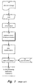
- Figure 1 is a flow chart illustrating a prior art method of processing a scan line.
- a document (100) containing an image is scanned (110) and then normalized (120). Exposure control (shading correction) is then performed (130) prior to color transformation (140) and data compression (150). The resulting information is then sent to the scan line buffer 170 or further application dependent processing is performed (160).
- the standard solution adopted in many desktop scanner applications and digital copiers is to perform a first preview scan at a low resolution.
- the so obtained image is analyzed to determine the paper color of the original (or background value) and other parameters.
- the values so obtained are then used to set the scanner controls, after which the final scan is performed.
- a solution sometimes used is to assume a worst case or a typical case. If the assumption errs towards a high lightness, the scanned image will not have a white background, yielding a smudgy appearance, decreasing the performance of image compression algorithms, and consuming more ink or toner when the image is printed. If the assumption errs towards a low lightness, detail will be lost in the highlights of the image, yielding a washed out appearance.
- statistical methods are used to estimate the reflectance of the paper and align the tone gamut to the dynamic range of a digital input device such as a scanner during a single scan.
- the estimate is refined during the scan. This refinement increases the robustness with respect to unfavorable originals (e.g., originals with a dark border) and at the same time also can take into account such phenomena as the change of the response of the sensor due to thermal effect during slow scans.
- TRC tone reproduction curve
- US-A-5 086 485 (LIN YING-WEI) 4 February 1992 discloses apparatus for determining a background level of an image to be scanned.
- the apparatus builds a series of histograms of the image each corresponding to a line of the image, analyzes each of the histograms, and averages the results of the analysis, to continually update a background level during the scan of the image.
- the apparatus may be implemented with a simple architecture capable of operating at high speed.
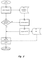
- FIG. 2 is a flow chart illustrating shading correction exposure control practiced according to one embodiment of the present invention.
- a line is scanned (200).
- a histogram is then collected (210) for the scanned line and this information is used to update a cumulative histogram 230.
- Test 240 is then made to determine whether the exposure should be recomputed. If so, then cumulative histogram 230 is used to estimate exposure (250) and a new TRC (tone response curve) 270 is computed (260). TRC 270 is then applied (280) yielding corrected scan line 290. If, on the other hand, it is determined in test 240 that exposure for this scan line is not to be recomputed, then TRC 270 is simply applied (280) to yield corrected scan line 290.
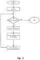
- Figure 3 is a flow chart illustrating histogram collection practiced according to one embodiment of the present invention.
- a line is scanned (300) and a pixel counter is set to one (310).
- Test 320 determines whether the end of the scan line has been reached, i.e., whether the pixel counter has exceeded the line length. If the end of the scan line has not been reached, then the tone level is set to the scanned value of the pixel (340). The histogram entry for the tone level of the pixel is incremented (350) and the pixel counter is incremented (360). This process is repeated until test 320 indicates the end of the scan line has been reached, at which time the histogram collection for the scan line ends (370).
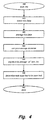
- Figure 4 is a flow chart illustrating exposure estimation practiced according to one embodiment of the present invention.
- the line is scanned (400) and data associated with the scanned line is counted (410).
- the data is then averaged (420) and the average deviation is computed (430).
- the exposure can then be calculated (440) as being the average minus d times the average deviation.
- the next scan line is then determined (450) prior to completion (460).
- Figure 5 illustrates a red color histogram of a color photograph collected according to one embodiment of the present invention. More precisely, a photographic color print is scanned and for each level in the 8-bit red channel the number of pixels (frequency) with that tone level is counted. A low tone level value indicates a dark tone and a high tone level value indicates a light tone.
- the first peak corresponds to black pixels such as those pixels in text and the second peak corresponds to shadows.
- the left peak corresponds to the highlights and the right peak corresponds to the paper background.
- the approach taken is to estimate the tone level for which the peak for the paper occurs.
- the exposure control or shading control consists of building a tone reproduction curve that maps this peak tone level into the value 255 representing white. This procedure aligns the tone gamut of the image with the dynamic range of the scanner, so that a predictable and distinct signal is generated for each tone level.
- the arrow in the preceding figure indicates a common problem that occurs in the analog to digital conversion, namely a binning error.
- the device converts the tone level of the photosites with this same reflectance and a higher probability into the value 223 than into the value 224. Because of this non-monotonicity, the peak cannot be found with local methods, i.e., by scanning the histogram from right to left until a maximum is reached.
- the binning errors can be so severe that smoothing the data with various methods such as moving window averages or applying least-squares fits (Savitzky-Golay smoothing filters) does not allow for robust estimations.
- Figure 6 illustrates the light end of the histogram for a blank sheet of premium ink jet paper collected according to one embodiment of the present invention.
- This paper is characteristic in that it contains fluorescent substances that interact with peaks from the fluorescent light source used in some scanners. This produces a greater response in the green channel and a reduced response in the red channel. For this reason one can limit the method to examining the red channel, because a tone map that maps the red peak into 255 will also map the green and blue peaks to that value.
- the average deviation or mean absolute deviation provides for a more robust estimation for the variability in the data. Also in this case one can use the maximum likelihood estimator to allow for the non-normality of the distribution.
- d 2 is a good choice, but analysis of a large number of different images might suggest a different value. Estimating the tone level of the paper means that this method is independent of the image and the particular artistic use of the tone range used to express it.
- the average deviation increases as one scans down the page, so that the histograms are not identically distributed across scan lines. This is especially the case in an application such as color facsimile where the scanning speed is bounded by the communication line speed.
- the background is not a gradient with increasing darkness.
- a manual override button on the machine can be employed to revert to a conventional approach.
- the original can simply be rotated 180 degrees so that the background will have a gradient with decreasing darkness and then scanned or re-scanned.
- stationary means that the probabilistic structure of different portions of the scanned document is the same.
- the probability distribution of the reflectance of the background is the same at all of the scan lines and the joint distribution of the reflectance of the background for pairs of scan lines distance h apart is always the same, and so forth.
- a table is created mapping each possible random number generated to a particular scan line to be evaluated.
- a sequence of random numbers is then generated and the associated scan lines are evaluated.
- the seed number fora sequence can be chosen by ballot from the tables in "The Rand Corporation, A Million Digits with 100, 000 Normal Deviates, Free Press, Glencoe, 1955".
- a different pseudo-random number generator for exponentially distributed numbers could have been used and a different seed number could have been used. Each would produce a different but statistically equivalent set.
- the aim of the dynamic exposure control mechanism is to align the gamut of the original image with the dynamic range of the scanner system.
- the appearance of an image depends upon the shape of the tone reproduction curve (TRC).
- TRC tone reproduction curve
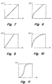
- FIGS 7-11 illustrate TRCs suitable for use within an embodiment of the present invention.
- Many TRC design methods have been described in the literature since Leonardo da Vinci's Chiaroscuro. The following is a brief discussion of some practical considerations associated with selection of a TRC.
- tone reproduction refers to the appearance of images
- tone reproduction curves are discussed in a perceptually linear space rather than in a space that is linear in intensity.
- spaces that are linear in intensity are the red, green and blue channels of scanners and display monitors.
- Examples of approximately perceptual linear spaces are optical density and L*.
- Figure 7 shows the identity tone map, where the tone levels are left unchanged.
- Figure 8 shows a tone correction by offset wherein a fixed value is added to the tone levels so that all levels higher than the exposure level (i.e., the level of the background) are mapped into the maximum value. The slope of the curve is unchanged signifying that the macro contrast or apparent contrast of the image is not changed.
- a knee has to be introduced at a threshold value so that the darkest portion of the image remains dark.
- FIG 10 shows Eschbach's method, in which an exponential correction is applied. Although the appearance of the image is improved over the use of the TRC of Figure 7, this TRC has the objectional property that the linear proportion of the tone values in the image are destroyed, thus altering the expression of the image.
- TRC is separated into three regions. They are called toe, corresponding to dark values, the shoulder, corresponding to light values, and the mid-tones, where most of the pictorial information in an image tends to reside.
- Figure 11 shows a typical sigmoidal TRC.
- the sigmoidal shape has the following properties.
- the toe is designed to cover the shadow portion of the image.
- the low slope keeps dark colors dark. For example, this ensures that the black text in documents stays black and can be easily processed, for example, by an optical character recognition (OCR) stage in the receiving system because the edges remain sharper.
- OCR optical character recognition
- the mid-tone region is kept straight, so that the reproduction of these important tone values is linear.
- the slope of the curve is called gamma, not to be confused with the gamma used to designate the exponent in an exponential TRC.
- the value of gamma is chosen so that it compensates for the flare in the system and for the apparent contrast reduction induced by the viewing conditions.
- the shoulder tapers off so that the variability in the tone level of the background can be controlled while some detail can be preserved in the highlights of the image.
- the dynamic exposure control method decouples the design of the TRC from the actual data representing an image.
- the analysis on the data is used to determine the parameters for a TRC designed for optimal system performance. Examples of the parameters are the position and curvature of the toe and shoulders of the TRC.
- the statistical approach has the advantage that instead of examining the signals pertinent to an image, statistical methods are used to estimate the tone level of the paper or other background that constitutes the substrate carrying an image or document. This decouples the tone reproduction characteristic from the exposure control necessary to map the tone range of the image into the dynamic range of the scanner designed for a worst case situation.
- the statistical method is incremental because the statistical data is gathered during the scan. While the scan progresses, the estimate is refined based upon the increased amount of data available from the accumulated histogram.
Landscapes
- Engineering & Computer Science (AREA)
- Multimedia (AREA)
- Signal Processing (AREA)
- Facsimile Image Signal Circuits (AREA)
- Image Input (AREA)
- Facsimile Scanning Arrangements (AREA)
Claims (7)
- Ein Belichtungssteuerverfahren für eine digitale Eingabevorrichtung, das folgende Schritte aufweist:wobei das für die abgetastete Linie gesammelte Histogramm (230) verwendet wird, um das Reflexionsvermögen des Mediums indirekt zu schätzen, indem eine auf dem aktualisierten kumulativen Histogramm (230) basierende Schätzung überarbeitet wird, und um dadurch eine geschätzte Tonskala des Mediums auf den Dynamikbereich der digitalen Eingabevorrichtung auszurichten, um während eines einzelnen Scanvorgangs eine Tonantwortkurve (260) zu erzeugen; undSammeln eines Histogramms (210) für eine abgetastete Linie (200) auf einem Medium;Aktualisieren eines kumulativen Histogramms (230) auf der Basis des für die abgetastete Linie gesammelten Histogramms; undVerwenden des für die abgetastete Linie gesammelten Histogramms, um das Reflexionsvermögen des Mediums (250) zu schätzen;
wobei der Schritt des Schätzens des Reflexionsvermögens (250) des Mediums ein Bestimmen eines durchschnittlichen Tonwerts (420) in dem kumulativen Histogramm (230) umfaßt. - Das Verfahren gemäß Anspruch 1, bei dem der Schritt des Schätzens des Reflexionsvermögens (250) des Mediums ein Bestimmen eines durchschnittlichen Tonabweichungswerts (430) in dem kumulativen Histogramm (230) umfaßt.
- Das Verfahren gemäß Anspruch 1 oder 2, bei dem der Schritt des Schätzens des Reflexionsvermögens (250) des Mediums für vorbestimmte abgetastete Linien durchgeführt wird.
- Das Verfahren gemäß einem der Ansprüche 1 - 3, bei dem der Schritt des Schätzens des Reflexionsvermögens (250) des Mediums für zufällig bestimmte abgetastete Linien durchgeführt wird.
- Das Verfahren gemäß Anspruch 1, bei dem der Schritt des Schätzens des Reflexionsvermögens des Mediums ein Bestimmen eines durchschnittlichen Tonwerts (420) für einen bestimmten Farbkanal in dem kumulativen Histogramm (230) umfaßt.
- Das Verfahren gemäß Anspruch 5, bei dem der durchschnittliche Tonwert ein durchschnittlicher Tonabweichungswert (430) ist.
- Eine Belichtungssteuervorrichtung für eine digitale Eingabevorrichtung, wobei die Vorrichtung das in einem der vorhergehenden Ansprüche dargelegte Verfahren verwendet.
Applications Claiming Priority (2)
| Application Number | Priority Date | Filing Date | Title |
|---|---|---|---|
| US724711 | 1996-09-30 | ||
| US08/724,711 US5901243A (en) | 1996-09-30 | 1996-09-30 | Dynamic exposure control in single-scan digital input devices |
Publications (3)
| Publication Number | Publication Date |
|---|---|
| EP0833498A2 EP0833498A2 (de) | 1998-04-01 |
| EP0833498A3 EP0833498A3 (de) | 1999-01-27 |
| EP0833498B1 true EP0833498B1 (de) | 2002-07-24 |
Family
ID=24911573
Family Applications (1)
| Application Number | Title | Priority Date | Filing Date |
|---|---|---|---|
| EP97307078A Expired - Lifetime EP0833498B1 (de) | 1996-09-30 | 1997-09-12 | Dynamische Steuerung der Belichtung in digitalen Eingabeeinrichtungen |
Country Status (4)
| Country | Link |
|---|---|
| US (1) | US5901243A (de) |
| EP (1) | EP0833498B1 (de) |
| JP (1) | JPH10126582A (de) |
| DE (1) | DE69714169T2 (de) |
Families Citing this family (18)
| Publication number | Priority date | Publication date | Assignee | Title |
|---|---|---|---|---|
| US6493468B1 (en) * | 1998-05-06 | 2002-12-10 | Canon Kabushiki Kaisha | Image processing apparatus and method |
| US6236751B1 (en) * | 1998-09-23 | 2001-05-22 | Xerox Corporation | Automatic method for determining piecewise linear transformation from an image histogram |
| US7263484B1 (en) | 2000-03-04 | 2007-08-28 | Georgia Tech Research Corporation | Phonetic searching |
| US7050196B1 (en) * | 2000-06-20 | 2006-05-23 | Eastman Kodak Company | Color printer calibration |
| US6735330B1 (en) * | 2000-10-17 | 2004-05-11 | Eastman Kodak Company | Automatic digital radiographic bright light |
| US6987880B2 (en) * | 2001-03-22 | 2006-01-17 | Sharp Laboratories Of America, Inc. | Efficient document boundary determination |
| US20030011790A1 (en) * | 2001-07-05 | 2003-01-16 | Eastman Kodak Company | Correcting exposure and tone scale of digital images using a plurality of transforms |
| US6970607B2 (en) * | 2001-09-05 | 2005-11-29 | Hewlett-Packard Development Company, L.P. | Methods for scanning and processing selected portions of an image |
| JP4314822B2 (ja) * | 2002-02-13 | 2009-08-19 | 株式会社ニコン | 画像処理装置、画像処理方法、及び画像処理プログラム |
| EP1565907A4 (de) * | 2002-10-18 | 2006-01-18 | Ser Solutions Inc | Verfahren und vorrichtung zur berwachung und evaluierung von audiodaten mittels spracherkennung |
| US7133828B2 (en) | 2002-10-18 | 2006-11-07 | Ser Solutions, Inc. | Methods and apparatus for audio data analysis and data mining using speech recognition |
| US7076427B2 (en) | 2002-10-18 | 2006-07-11 | Ser Solutions, Inc. | Methods and apparatus for audio data monitoring and evaluation using speech recognition |
| US7317829B2 (en) * | 2003-12-12 | 2008-01-08 | Microsoft Corporation | Background color estimation for scanned images |
| US7568628B2 (en) | 2005-03-11 | 2009-08-04 | Hand Held Products, Inc. | Bar code reading device with global electronic shutter control |
| US7770799B2 (en) | 2005-06-03 | 2010-08-10 | Hand Held Products, Inc. | Optical reader having reduced specular reflection read failures |
| US7724981B2 (en) * | 2005-07-21 | 2010-05-25 | Ancestry.Com Operations Inc. | Adaptive contrast control systems and methods |
| WO2007028166A2 (en) * | 2005-09-02 | 2007-03-08 | Blindsight, Inc. | A system and method for detecting text in real-world color images |
| JP5103984B2 (ja) * | 2007-03-29 | 2012-12-19 | 株式会社ニコン | 画像処理装置、撮像装置、および画像処理プログラム |
Family Cites Families (32)
| Publication number | Priority date | Publication date | Assignee | Title |
|---|---|---|---|---|
| DE3408107C2 (de) * | 1983-03-06 | 1996-05-30 | Canon Kk | Halbtonfarbbildaufzeichnungsgerät |
| JPS60182870A (ja) * | 1984-03-01 | 1985-09-18 | Canon Inc | 画像処理装置 |
| US4729016A (en) * | 1985-05-06 | 1988-03-01 | Eastman Kodak Company | Digital color image processing method and apparatus employing three color reproduction functions for adjusting both tone scale and color balance |
| US4642683A (en) * | 1985-05-06 | 1987-02-10 | Eastman Kodak Company | Digital image processing method for images with bimodal tone value distribution |
| JP2556486B2 (ja) * | 1986-11-14 | 1996-11-20 | キヤノン株式会社 | フィルム読取装置 |
| US4805218A (en) * | 1987-04-03 | 1989-02-14 | Dragon Systems, Inc. | Method for speech analysis and speech recognition |
| US5130788A (en) * | 1987-05-21 | 1992-07-14 | Minolta Camera Kabushiki Kaisha | Shading correction using FIFO memory for correction data |
| IL83213A (en) * | 1987-07-16 | 1991-08-16 | Technion Res & Dev Foundation | Intelligent scan image sensor |
| US5430559A (en) * | 1988-12-22 | 1995-07-04 | Minolta Camera Kabushiki Kaisha | Image reading apparatus with improved output correction of image signal |
| US5028784A (en) * | 1989-04-11 | 1991-07-02 | Fuji Photo Film Co., Ltd. | Method for generating radiation image signals, image processing method, and radiation image read-out apparatus |
| CA2020627C (en) * | 1989-07-07 | 1995-06-27 | Yuzo Koike | Image processing apparatus |
| JPH0389674A (ja) * | 1989-08-31 | 1991-04-15 | Fuji Xerox Co Ltd | 原稿読み取り装置 |
| JP2776923B2 (ja) * | 1989-11-27 | 1998-07-16 | 株式会社リコー | 原稿読取装置 |
| US5150223A (en) * | 1989-11-30 | 1992-09-22 | Eastman Kodak Company | Copier with single pass auto exposure |
| JPH0722337B2 (ja) * | 1990-01-08 | 1995-03-08 | 富士ゼロックス株式会社 | 画像処理装置におけるフィルム画像パラメータ抽出方式 |
| US5046118A (en) * | 1990-02-06 | 1991-09-03 | Eastman Kodak Company | Tone-scale generation method and apparatus for digital x-ray images |
| JP2610696B2 (ja) * | 1990-05-30 | 1997-05-14 | シャープ株式会社 | 画像信号処理装置 |
| JPH0722338B2 (ja) * | 1990-06-19 | 1995-03-08 | 富士ゼロックス株式会社 | 画像読取り装置 |
| US5086485A (en) * | 1990-10-19 | 1992-02-04 | Xerox Corporation | Method and apparatus for dynamically setting a background level |
| GB9023013D0 (en) * | 1990-10-23 | 1990-12-05 | Crosfield Electronics Ltd | Method and apparatus for generating representation of an image |
| US5265200A (en) * | 1990-11-01 | 1993-11-23 | International Business Machines Corporation | System and method for automatic image saturation, gamma, and exposure correction in a digitizing video capture system |
| JP3130593B2 (ja) * | 1991-01-08 | 2001-01-31 | 株式会社リコー | 原稿読取り装置 |
| US5115189A (en) * | 1991-02-06 | 1992-05-19 | Hewlett-Packard Company | Anti-aliasing dithering method and apparatus for low frequency signal sampling |
| US5412489A (en) * | 1991-06-29 | 1995-05-02 | Minolta Camera Kabushiki Kaisha | Shading correction having a line memory read which generates an average reference level from a plurality of lines of a reference plate |
| JP2774014B2 (ja) * | 1992-03-12 | 1998-07-09 | 三田工業株式会社 | 濃度処理方法 |
| JP2819365B2 (ja) * | 1992-05-28 | 1998-10-30 | キヤノン株式会社 | 画像形成装置 |
| JP3083207B2 (ja) * | 1992-07-13 | 2000-09-04 | 京セラミタ株式会社 | 画像形成装置 |
| JPH0646255A (ja) * | 1992-07-23 | 1994-02-18 | Fuji Xerox Co Ltd | 画像処理装置 |
| US5347370A (en) * | 1992-12-28 | 1994-09-13 | Nisca Corporation | Shading correction method and apparatus |
| US5414538A (en) * | 1993-10-07 | 1995-05-09 | Xerox Corporation | Image-dependent exposure enhancement |
| US5347374A (en) * | 1993-11-05 | 1994-09-13 | Xerox Corporation | Cascaded image processing using histogram prediction |
| JP3164744B2 (ja) * | 1994-12-21 | 2001-05-08 | 株式会社東芝 | 画像形成装置 |
-
1996
- 1996-09-30 US US08/724,711 patent/US5901243A/en not_active Expired - Lifetime
-
1997
- 1997-08-18 JP JP9221795A patent/JPH10126582A/ja active Pending
- 1997-09-12 EP EP97307078A patent/EP0833498B1/de not_active Expired - Lifetime
- 1997-09-12 DE DE69714169T patent/DE69714169T2/de not_active Expired - Lifetime
Also Published As
| Publication number | Publication date |
|---|---|
| EP0833498A3 (de) | 1999-01-27 |
| JPH10126582A (ja) | 1998-05-15 |
| EP0833498A2 (de) | 1998-04-01 |
| US5901243A (en) | 1999-05-04 |
| DE69714169T2 (de) | 2002-11-07 |
| DE69714169D1 (de) | 2002-08-29 |
Similar Documents
| Publication | Publication Date | Title |
|---|---|---|
| EP0833498B1 (de) | Dynamische Steuerung der Belichtung in digitalen Eingabeeinrichtungen | |
| US7924469B2 (en) | Image processing apparatus, image processing method, and program | |
| JP3759761B2 (ja) | 鮮鋭度の変更方法及び装置 | |
| US7068852B2 (en) | Edge detection and sharpening process for an image | |
| US6580825B2 (en) | Contrast enhancement of an image using luminance and RGB statistical metrics | |
| JP4333804B2 (ja) | 画像データの出力画像調整 | |
| JP5196987B2 (ja) | 画像処理装置及び画像処理方法、コンピュータプログラム及び記録媒体 | |
| US8395832B2 (en) | Image processing apparatus | |
| US7719574B2 (en) | Output image adjustment of image data | |
| US7502150B2 (en) | Color converting device, image forming apparatus, color conversion method, computer program and recording medium | |
| CN102547062A (zh) | 图像处理装置、图像形成装置、以及图像处理方法 | |
| JP4197276B2 (ja) | 画像処理装置、画像読取装置、画像形成装置、および画像処理方法 | |
| US6144778A (en) | Pixel weighted transition scanning to ameliorate swath scanner banding | |
| JP2008305099A (ja) | 画像処理方法、画像処理装置、画像形成装置、コンピュータプログラム、及び記録媒体 | |
| JP7391653B2 (ja) | 画像処理装置、画像処理方法、及びプログラム | |
| JP2009017208A (ja) | 画像処理装置、画像形成装置、画像処理方法、コンピュータプログラム及びコンピュータでの読み取りが可能な記録媒体 | |
| US20060096483A1 (en) | Method for optimised colour reproduction of a coloured original image | |
| JP2861410B2 (ja) | 画像処理装置 | |
| JP4099366B2 (ja) | 画像処理装置、画像読取装置、画像形成装置及び画像処理方法 | |
| JP2006011754A (ja) | 画像処理装置および画像処理方法 | |
| JP2002016798A (ja) | 画像読み取り方法、記録媒体および画像読み取り装置 | |
| US20230051281A1 (en) | Color correction of an image | |
| JP3342623B2 (ja) | 画像データ変換方法及び装置 | |
| Beretta | Dynamic exposure control in color scanners | |
| JPH11317880A (ja) | 画像再生方法および装置 |
Legal Events
| Date | Code | Title | Description |
|---|---|---|---|
| PUAI | Public reference made under article 153(3) epc to a published international application that has entered the european phase |
Free format text: ORIGINAL CODE: 0009012 |
|
| AK | Designated contracting states |
Kind code of ref document: A2 Designated state(s): DE FR GB |
|
| PUAL | Search report despatched |
Free format text: ORIGINAL CODE: 0009013 |
|
| AK | Designated contracting states |
Kind code of ref document: A3 Designated state(s): AT BE CH DE DK ES FI FR GB GR IE IT LI LU MC NL PT SE |
|
| 17P | Request for examination filed |
Effective date: 19990726 |
|
| AKX | Designation fees paid | ||
| RBV | Designated contracting states (corrected) |
Designated state(s): DE FR GB |
|
| RAP1 | Party data changed (applicant data changed or rights of an application transferred) |
Owner name: HEWLETT-PACKARD COMPANY, A DELAWARE CORPORATION |
|
| GRAG | Despatch of communication of intention to grant |
Free format text: ORIGINAL CODE: EPIDOS AGRA |
|
| 17Q | First examination report despatched |
Effective date: 20011016 |
|
| GRAG | Despatch of communication of intention to grant |
Free format text: ORIGINAL CODE: EPIDOS AGRA |
|
| GRAH | Despatch of communication of intention to grant a patent |
Free format text: ORIGINAL CODE: EPIDOS IGRA |
|
| GRAH | Despatch of communication of intention to grant a patent |
Free format text: ORIGINAL CODE: EPIDOS IGRA |
|
| GRAA | (expected) grant |
Free format text: ORIGINAL CODE: 0009210 |
|
| AK | Designated contracting states |
Kind code of ref document: B1 Designated state(s): DE FR GB |
|
| REG | Reference to a national code |
Ref country code: GB Ref legal event code: FG4D |
|
| REF | Corresponds to: |
Ref document number: 69714169 Country of ref document: DE Date of ref document: 20020829 |
|
| ET | Fr: translation filed | ||
| PLBE | No opposition filed within time limit |
Free format text: ORIGINAL CODE: 0009261 |
|
| STAA | Information on the status of an ep patent application or granted ep patent |
Free format text: STATUS: NO OPPOSITION FILED WITHIN TIME LIMIT |
|
| 26N | No opposition filed |
Effective date: 20030425 |
|
| PGFP | Annual fee paid to national office [announced via postgrant information from national office to epo] |
Ref country code: GB Payment date: 20090929 Year of fee payment: 13 |
|
| PGFP | Annual fee paid to national office [announced via postgrant information from national office to epo] |
Ref country code: DE Payment date: 20090929 Year of fee payment: 13 |
|
| GBPC | Gb: european patent ceased through non-payment of renewal fee |
Effective date: 20100912 |
|
| REG | Reference to a national code |
Ref country code: FR Ref legal event code: ST Effective date: 20110531 |
|
| REG | Reference to a national code |
Ref country code: DE Ref legal event code: R119 Ref document number: 69714169 Country of ref document: DE Effective date: 20110401 |
|
| PG25 | Lapsed in a contracting state [announced via postgrant information from national office to epo] |
Ref country code: FR Free format text: LAPSE BECAUSE OF NON-PAYMENT OF DUE FEES Effective date: 20100930 Ref country code: DE Free format text: LAPSE BECAUSE OF NON-PAYMENT OF DUE FEES Effective date: 20110401 |
|
| PG25 | Lapsed in a contracting state [announced via postgrant information from national office to epo] |
Ref country code: GB Free format text: LAPSE BECAUSE OF NON-PAYMENT OF DUE FEES Effective date: 20100912 |
|
| PGFP | Annual fee paid to national office [announced via postgrant information from national office to epo] |
Ref country code: FR Payment date: 20091006 Year of fee payment: 13 |