EP0826837B2 - Installationselement für Sanitärinstallationen - Google Patents
Installationselement für Sanitärinstallationen Download PDFInfo
- Publication number
- EP0826837B2 EP0826837B2 EP97112651A EP97112651A EP0826837B2 EP 0826837 B2 EP0826837 B2 EP 0826837B2 EP 97112651 A EP97112651 A EP 97112651A EP 97112651 A EP97112651 A EP 97112651A EP 0826837 B2 EP0826837 B2 EP 0826837B2
- Authority
- EP
- European Patent Office
- Prior art keywords
- element according
- installation element
- moulded body
- moulded
- installation
- Prior art date
- Legal status (The legal status is an assumption and is not a legal conclusion. Google has not performed a legal analysis and makes no representation as to the accuracy of the status listed.)
- Expired - Lifetime
Links
Images


Classifications
-
- E—FIXED CONSTRUCTIONS
- E03—WATER SUPPLY; SEWERAGE
- E03D—WATER-CLOSETS OR URINALS WITH FLUSHING DEVICES; FLUSHING VALVES THEREFOR
- E03D11/00—Other component parts of water-closets, e.g. noise-reducing means in the flushing system, flushing pipes mounted in the bowl, seals for the bowl outlet, devices preventing overflow of the bowl contents; devices forming a water seal in the bowl after flushing, devices eliminating obstructions in the bowl outlet or preventing backflow of water and excrements from the waterpipe
- E03D11/13—Parts or details of bowls; Special adaptations of pipe joints or couplings for use with bowls, e.g. provisions in bowl construction preventing backflow of waste-water from the bowl in the flushing pipe or cistern, provisions for a secondary flushing, for noise-reducing
- E03D11/14—Means for connecting the bowl to the wall, e.g. to a wall outlet
- E03D11/143—Mounting frames for toilets and urinals
- E03D11/146—Mounting frames for toilets and urinals with incorporated cistern
Definitions
- the invention relates to an installation element for plumbing installations, comprising a molded body made of insulating material, in which at least one flushing cistern with drainage pipe is arranged. Furthermore, the invention relates to a shaped body for such an installation element.
- Such an installation module is from the German utility model DE-8907973 known.
- the necessary for the supply and disposal of a sanitary appliance lines and components and the necessary for attaching the sanitary fixture are stored in a foamed molding.
- a fire protection layer spread substantially over the entire block area is formed between the front and rear wall. This layer is firmly bonded during the manufacturing process of the shaped body with the molding material, so that it becomes part of the molding.
- the lines and components are supported in accordance with the foaming of the molding material mass against buoyancy.
- a toilet block which comprises a PUR-shaped body, in the inner parts, in particular a cistern, are molded directly. This means that the inner parts are encapsulated by the plastic.
- cladding blocks are described, which provide a smooth, flowable surface at the front, but are open at the back and not formed in its interior to the sanitary elements.
- strands for piping shown. For this purpose, the cladding elements on inner contour sections, can be introduced into the pipes.
- a sheet of the Schell company with the printing note 1/95 shows on page 2.3 a urinal flush-mounted flush valve DN 15 VERONA. This obviously includes a two-piece Styrofoam sheath. However, it is not clear from the catalog sheet whether the Styrofoam coating serves only as transport packaging or should be plastered into the wall.
- connection boxes are mainly intended for wall mounting and are, as far as the prospectus reveals, in one piece, partially with directly molded pipe sections designed.
- the DE 30 35 935 A1 deals with a connector between a sanitary appliance and a water pipe.
- This connecting piece is arranged in a cuboid of at least two nested parts which surround the connecting piece at least partially positively.
- the parts are made of synthetic foam and are held together with a tape or a wire or a string.
- the assembly piece formed from the two elements is housed in a wall slot and then plastered. Alignment aids for plastering are also described in this document.
- a flush-mounted fitting is described, which is inserted in a surrounding shell made of a foam.
- the shell consists of two half-shells glued together. After inserting the rear part of the shell into a masonry and then plastering, the front part of the shell is removed to expose the controls of the fitting. As a result, the visible part of the fitting is protected during the Verputzvorgangs.
- a disadvantage of some of these devices is the relatively complex production of the installation blocks, since the sanitary elements must be fixed before filling the cavities with sound-absorbing material. In addition, it must be ensured that the sound-absorbing material is introduced so that it also reaches almost all the cavities and causes a substantially complete encapsulation of the sound-producing installation components.
- the present invention therefore proposes to construct the molded article from a plurality of individual parts, which are prefabricated separately from the cistern with drainage pipe to be installed.
- the inner contour of the shell elements is easily tuned so that the cistern with drain pipe is inserted only in the appropriate place and fixed by joining another shell element. As a result, a complete enclosure of the cistern with drain pipe can be achieved. Only the desired Entrances and exits can be accessible through corresponding openings in the molding.
- the invention further offers the advantage that the inner contour of the shell elements can be formed for installation of various cisterns with drain pipe, so that there is a flexible modular system. If necessary, larger distances would have to be bridged by additional insert elements. Due to the shell construction, an additional condensation insulation, as it is customary in the prior art, omitted.
- the entire cistern can be excellent sound insulation by the molding without major problems in the production of the installation block in contrast to the prior art. For example, fixing the cistern to buoyancy need not be provided, as is partially the case in the prior art.
- the shaped body is made available from a box consisting of two half-shells.
- the reduction to only two half-shells results in a great simplification of the molded body, also with regard to the joining of the installation module.
- the cistern with drain pipe is inserted into one of the two half-shells and enclosed and fixed by placing the other half-shell.
- the dividing plane of the two half-shells runs parallel to the front and back of the molding. As a result, it is also very easy to achieve a dense joining of the two half-shells.
- the molded body has at a distance from the sound-insulating cistern with drainage pipe receiving openings. Furthermore, fastening means are provided which serve for insertion into the receiving openings, in particular for wall mounting. Such a design allows for a very simple arrangement of the installation element.
- the fasteners are attached to the designated place and pushed the molding. The molded body thus assumes the support or support and arrangement function for the cistern with drain pipe. Other fasteners that may need to be sound decoupled, need not be provided. Since the receiving openings are formed of sound-absorbing material, a sound-insulating attachment of the installation element is automatically brought about.
- the shell elements are interconnected via frictionally engaging male and female elements, in particular watertight.
- This simple connection method can be implemented very simply in terms of shape and ensures that it fits snugly together.
- the plug and receptacle elements can also be designed so that they are also insoluble and / or waterproof connectable.
- the shaped body can be formed on at least two different areas with different densities or insulation properties.
- the transition from different densities of a buffer effect is achieved, which also improves the insulation properties.
- the arrangement of areas of different densities can be done so that a stable support structure for the cistern with drain pipe is given in the molding and all other areas are filled with low-density material. As a result, the sound-insulating effect of the molding is optimized.
- the shaped body can be constructed in multiple layers.
- the individual layers may arise due to special requirements.
- a fire protection layer may be provided.
- the layers or regions may have different properties, e.g. Density, strength, sound insulation or fire protection have.
- the front side of the molded body substantially completely as a large-area mounting surface, in particular plasterable and tileable surface, formed and provided with a surface profiling, this can be used for applying plaster and subsequent tiling.
- the back and side surfaces may be similarly configured to be connected to wall structures accordingly.
- the corresponding configuration of the surface of the shaped body makes a corresponding provision of additional components, such as e.g. Expanded metal, no longer necessary for the adhesion of mortar.
- At least the area around the receiving openings of the shaped body may be formed sufficiently stable to provide a self-supporting molded body, without additional fastening means for the cistern with drain pipe are necessary.
- the receiving openings from the back to the front of the shaped body through the corresponding shell elements extend through and the fastening means on its front side accessible to the front end fastening means, in particular at least one threaded bore, are received by the external loading forces substantially from the Festests Trentsmitteln ,
- the fastening means can be locked by suitable fastening means relative to the molded body or it is possible to attach additional attachments to the fastening means, which exert no load on the molded body, since these are passed past the molded body.
- a toilet body could be bolted to the fasteners.
- the arrangement of the fastening means and the number of fastening devices then depends on the type of additional components to be attached. It can be provided fastening devices of various arrangement and with different distances, so that whole series of attachments can be connected with the fastening means.
- a very good fixation of the molding on the mounting bolts can be achieved in that the receiving openings are tapered from the back to the front of the molding and fastening bolts are provided as fastening means, which are adapted accordingly in the outer contour. Since the receiving openings extend through at least two shell elements, they are additionally centered thereby. This embodiment also offers a simplification of assembly, since the fastening bolts always sit with a slight adhesive fit in the receiving openings, and beyond no reversed attachment of the molding to fastening bolts is possible.
- the attachment means may have an abutment surface for abutment with a rear side region of the molding, and an end plate may be provided for connection to the end face of the attachment means which abuts the front surface of the molding so that it abuts between the abutment surfaces on the attachment means and the end plate is clamped.
- the end plate ensures a large-scale investment in the molding and for a good power distribution of the clamping force on the pressure surface. As a result, even a molded body made of relatively soft material can be fastened very well.
- the end plate can also be used to arrange other components. It can also be used several end plates.
- a mounting rail may be provided, and the fastening means may comprise guide means for laterally pushing or attaching to the mounting rail.
- a holding in the loading direction on the mounting rail is also realized.
- locking means may be provided for locking the fastening means to the mounting rail.
- these are integrated in the element.
- the molded body made of foamed plastic, in particular polystyrene to produce.
- rib elements are arranged in the interior of the molded body, which rest in register on the sanitary elements in a substantially registering manner and fix them.
- the contact surface between the sanitary elements and the molded body is minimized.
- the cavities formed between the individual rib elements within the shaped body additionally serve for sound insulation.
- molding pockets for receiving and / or attaching additional sanitary elements and / or fastening or setting-up devices can be provided at least on the front and / or rear side of the molded body.
- the components may e.g. accurately inserted into these mold pockets and e.g. be locked on the cover plate using the fastening bolts.
- mold bags can serve to postpone the entire molding on a support frame and to support this. Thereby, e.g. a free installation in the room using a base frame possible.
- a pipe clamp, a drain pipe and a mold pocket for attaching the pipe clamp may be provided, wherein the drain pipe is mounted soundproofed.
- the clamp is at least partially inserted into a mold pocket on the molding and held there, possibly through the end plate. This automatically results in a soundproof attachment of the drain pipe, so that no additional soundproof mounting for this must be provided.
- For improved assembly may further be provided that on the outside of the molding assembly marks are formed. Thus, this can be exactly aligned when mounting.
- Shaped deformable projections may be provided, which allow a gradual clamping for adjusting in the preassembled state. These projections are used to facilitate assembly and are deformed or destroyed after alignment.
- a fastening means (or more) may be provided for attachment to the upper edge region of the molding and for wall connection.
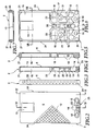
- This in Fig. 1 installation element shown has a molded body 1 made of a sound-insulating material, preferably foamed polystyrene on.
- the molded body 1 consists of a front shell 2 and a rear shell 3.
- a cistern 4 with a drain pipe (as in Fig. 16 ) built-in.
- the lower end of the drain pipe 5 protrudes at the front side 6 of the molded body 1 ( Fig. 1 ).
- the installation element off Fig. 1 for plumbing installations is attached via a mounting rail 9 to a wall and clamped over a cover plate 10.
- a mounting rail 9 to a wall and clamped over a cover plate 10.
- protruding threaded rods 11 show that serve for the cultivation of a toilet body.
- the front shell 2 has a substantially flat front side 6, which is provided with a surface profiling 12, as shown in detail in FIG Fig. 2 is shown. Apart from this surface profiling 12, the front side 6, as can be seen from the side view, substantially flat. Furthermore, in the front shell 2, an access opening 13 for later engagement of actuators in conjunction with the cistern 4 is present. At the lower end of the front shell 2 there is an outlet opening 14 for the drainage pipe 5 of the cistern 4. In addition, at the lower end two mutually spaced receiving openings 15 extend, which serve in a later described manner for fastening the installation element.
- a relatively large-volume receiving space 16 is provided for receiving the cistern 4.
- a stable rib structure 17 with a plurality of cavities 18.
- the rib structure 17 extends approximately over half the height of the front shell 2 and serves essentially to stabilize the lower region, wherein the cavities 18 reinforce the sound insulation.
- cup-shaped ribs 19 are provided which support the drain pipe 5 with built-in cistern 4. Between these cup-shaped ribs cavities 20 are also arranged.
- a plurality of locking pins 21 and plug ribs 22 are also arranged, which serve for positioning on the rear shell 3, as will be described in more detail below.
- a receiving pocket 23 is arranged, which serves for arranging further components.
- Fig. 3 It can be seen that the side surfaces 24 of the front shell 2 are also provided with a surface profiling 25.
- the rear shell 3 is shaped so that it can be fitted in register on the front shell 2 or vice versa.
- a large-volume receiving space 26 for receiving the cistern 4 is provided in the upper portion of the rear shell 3.
- On the sides of the receiving space 26 are support ribs 27, which, as in Fig. 14 can be seen, are adapted to the outer contour of the cistern 4, so that it rests on the ribs 27.
- a connection opening 28 open from the rear which is accessible from the rear side 29 of the rear shell 3.
- About the connection opening 28 is later the water supply of the cistern. 4
- the lower region of the rear shell 3 has, similar to the front shell 2, a rib structure 30 with cavities 31 for increasing the stability with good sound insulation properties. In the middle of this area are correspondingly in register with the front shell 2 ribs 32 and cavities 33 for enclosing and soundproofing of the drain pipe 5 of the cistern. 4
- plug receptacles 34 and plug-in slots 35 for receiving the plug bolts 21 and plug ribs 22 are incorporated in the region of the rib structure. Furthermore, located in the lower region of the rear shell 3, the matching halves of the receiving openings 15th
- the rear side 29 of the rear shell 3 is formed in the lower region with a shoulder 36, which serves to receive the mounting rail 9, so that the back 29 can rest flush with the wall.
- the side surfaces 37 of the rear shell 3 are also provided with a surface profiling 38, in particular with reference to FIG Fig. 9 you can see.
- Fig. 15 the closed molded body 1 with the front shell 2 and the rear shell 3 can be seen.
- Fig. 16 Cistern 4 shown installed with the drain pipe 5.
- FIGS. 17 and 18 Based on FIGS. 17 and 18 the installation of the cistern 4 can be seen in the molding 1. This rests on the support ribs 27 of the receiving space 26 of the rear shell 3. Similarly, the drain pipe 5 is located on the ribs 32nd Die Fig. 18 illustrates how after placing the front shell 2 of the cistern 4 and the drain pipe 5 is completely enclosed except for the necessary entry and exit points and clearly fixed in position.
- the rib structures 17 of the front shell 2 and 33 of the rear shell 3 abut each other and the edges of the shells 2 and 3 are equipped so that they engage in soundproofing.
- a lid 40 On the front side 39 of the cistern 4 is a lid 40 which can be removed for mounting an actuating mechanism.
- the attachment is effected by means of the fastening rail 9, which has a substantially U-shaped cross section with outwardly facing end webs 41 on the U-legs 42.
- the mounting rail 9 is above the openings 43 at the Wall attachable.
- a fastening bolt 44 On the mounting rail 9 can be pushed a fastening bolt 44, which has a tapered plug portion 45 and at its thicker end a C-shaped mounting plate 46.
- the mounting plate 46 is configured in cross-section so that it can be pushed laterally onto the mounting rail 9, but can not be removed perpendicular to the wall.
- the contour of the plug portion 45 is adapted to the inner contour of the receiving openings 15 in the molded body 1.
- the length of the plug-in portion 45, starting from the directly adjacent to this surface 47 of the mounting plate 46 to the end face 48 of the plug portion 45 is slightly less than the total thickness of the molded body 1 in the region of the receiving openings 15.
- the mounting plate 46 may be integral with the plug portion 45th be formed or made separately and attached to this.
- two threaded holes 49 and 50 are arranged in the end face 48 of the plug portion 45. These serve on the one hand to screw in the Fig. 1 shown threaded rods 11 and on the other for screwing in the fixing screws 51 (see also Fig. 1 ) for attaching the end plate 10 to the front side 6 of the molded body 1.
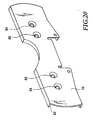
- the end plate 10 is in Fig. 20 shown.
- the end plate 10 has a collar 52 which in a groove 53 on the front shell 2 (see Fig. 2 ) in register.
- the bores 54 and 55 are each for receiving either the threaded rod 11 or the fixing screw 51, for which they are each provided with a reduction.
- a drain pipe 7 (see also Fig. 1 ) can also be attached to the molded body 1 sound-absorbing.
- the pipe clamp 8 is now fixed in the mold pocket 23.
- a screw 56 can still be used for attachment.
- the clamp 8 is made of plastic, so that a sound-insulating suspension of the drain pipe 7 is given. Based on Fig. 21 is also very easy to see how the collar 52 of the end plate 10 engages in the groove 53 in the front shell 2.
- the pipe clamp 8 is made in two parts and its lower part 8b can be attached to the upper part 8a, wherein a portion of the drain pipe 7 is encompassed form-fitting manner. By this attachment and the sound-absorbing suspension of the drain pipe 7 is brought to the molding 1.
- a fitter will prefer to do the installation after the meter break.
- 1 marks may be additionally attached to the molded body, which facilitate the alignment.
- Installation begins with the attachment of the mounting rail to the wall after the corresponding element positions and rail positions have been marked.
- the fastening bolts 44 are pushed onto the rail 9 and can be additionally fixed there by means of suitable, not shown facilities.
- the mold body 1 provided with the cistern 4 and drain pipe 5 can be pushed onto the fastening bolts 4, so that the plug-in sections 45 are located in the receiving openings 15. Due to the tapered design of both the openings 15 and the plug-in sections 45, a holding force is already achieved by the plugging operation. Now can still take place an orientation of the shaped body 1 by means of markings and subsequently the end plate 10 is placed on the front side 6. In advance, if desired, the pipe clamp 8 can still be used with the drain pipe 7 in the receiving pocket 23.
- the screws 51 are now screwed into the threaded bores 49 or 50, so that the molded body 1 is clamped between the surface 47 of the mounting plate 46 and the closure 16.
- the installation element is secured by pressing against the rail 9 or wall against moving.
- the threaded rods 11 are then screwed into the respective free threaded holes 49 or 50.
- the molded body 1 is designed over a large area and provided with a surface profiling 12, 25 and 38, this can be integrated into the wall structure. This means that immediately a plastering with mortar of the molding 1 and a subsequent tiling or masonry can take place.
- the rib structures 17 and 30 give the installation element sufficient strength, so that the attachment by means of the fastening bolts 44 is usually sufficient.
- the upper portion of the molded body 1 has sufficient strength, since it is additionally stabilized by the cistern 4. However, it is possible to fix the upper portion of the molded body 1 on the wall again.
- sound-insulating attachment means are used here.
- retaining grooves 57 may be introduced, which have a certain length and are open to the bottom of the molded body 1.
- Similar grooves may be appropriate.
- These grooves 57 can serve for pushing the molded body 1 in a wallless installation.
- a substructure may be provided on which the molded body 1 is attached. The fixation can in turn be made via the end plate 10 that the corresponding inserted into the groove 57 element fixed in this.
- the installation element according to the invention is in the assembly and in the production of great advantage. At the same time sufficient sound insulation is provided because all sound-generating parts are arranged sound-insulated in this or held on this.
- the separate preforming of half shells 2 is a significant advance in this field and results in significant cost savings.
- the self-supporting attachment can be configured in many ways. Due to the large number of possible combinations in terms of material composition, room weights, layer thicknesses and shapes in the field of plastics processing, the installation element can be given a wide variety of properties.
Landscapes
- Health & Medical Sciences (AREA)
- Life Sciences & Earth Sciences (AREA)
- Engineering & Computer Science (AREA)
- Hydrology & Water Resources (AREA)
- Public Health (AREA)
- Water Supply & Treatment (AREA)
- Sanitary Device For Flush Toilet (AREA)
- Diaphragms For Electromechanical Transducers (AREA)
- Bidet-Like Cleaning Device And Other Flush Toilet Accessories (AREA)
- Paper (AREA)
- Mattresses And Other Support Structures For Chairs And Beds (AREA)
- Pipe Accessories (AREA)
- Building Environments (AREA)
Applications Claiming Priority (2)
| Application Number | Priority Date | Filing Date | Title |
|---|---|---|---|
| DE19635759A DE19635759A1 (de) | 1996-09-03 | 1996-09-03 | Installationselement für Sanitärinstallationen |
| DE19635759 | 1996-09-03 |
Publications (3)
| Publication Number | Publication Date |
|---|---|
| EP0826837A1 EP0826837A1 (de) | 1998-03-04 |
| EP0826837B1 EP0826837B1 (de) | 2001-08-29 |
| EP0826837B2 true EP0826837B2 (de) | 2008-10-22 |
Family
ID=7804523
Family Applications (1)
| Application Number | Title | Priority Date | Filing Date |
|---|---|---|---|
| EP97112651A Expired - Lifetime EP0826837B2 (de) | 1996-09-03 | 1997-07-23 | Installationselement für Sanitärinstallationen |
Country Status (5)
| Country | Link |
|---|---|
| EP (1) | EP0826837B2 (es) |
| AT (1) | ATE204939T1 (es) |
| DE (2) | DE19635759A1 (es) |
| ES (1) | ES2163072T5 (es) |
| PT (1) | PT826837E (es) |
Families Citing this family (6)
| Publication number | Priority date | Publication date | Assignee | Title |
|---|---|---|---|---|
| DE20211758U1 (de) * | 2002-07-31 | 2003-12-11 | Franz Viegener Ii Gmbh & Co. Kg | Installationseinheit |
| ES2401888B9 (es) * | 2011-09-21 | 2014-10-14 | Fominaya, S.A. | Bastidor empotrable para sujeción de elementos sanitarios y su proceso de fabricación |
| NO20150209A1 (en) * | 2015-02-12 | 2016-08-15 | Arvid Hanstad As | Concealed toilet cistern assembly |
| FR3033581B1 (fr) * | 2015-03-11 | 2019-07-26 | Raccords Et Plastiques Nicoll | Bati support pour installation sanitaire du type encastree et procede de montage pour installation sanitaire du type encastree |
| EP3067477B1 (fr) * | 2015-03-11 | 2019-05-08 | Raccords et Plastiques Nicoll | Dispositif de fixation pour bâti support, ensemble de fixation comprenant un tel dispositif et procédé de fixation sur un bâti support |
| CA3200079A1 (en) * | 2020-11-26 | 2022-06-02 | Reuven ZION | Wall for tiling |
Family Cites Families (10)
| Publication number | Priority date | Publication date | Assignee | Title |
|---|---|---|---|---|
| DE1276561B (de) * | 1964-01-10 | 1968-08-29 | Hansa Metallwerke Ag | Installationswand |
| DE2637719C3 (de) * | 1976-08-21 | 1979-02-22 | Hansa Metallwerke Ag, 7000 Stuttgart | Unterputz-Armatur |
| CH649146A5 (en) * | 1980-07-01 | 1985-04-30 | Similor Sa | Connection fitting between a sanitary unit and a water line |
| DE3445474A1 (de) * | 1984-12-13 | 1986-06-19 | SCHWAB Sanitär-Plastic GmbH, 7417 Pfullingen | Sanitaerbaustein |
| DE3736679A1 (de) * | 1987-10-29 | 1989-05-11 | Anton Nachbar | Verbindungsanordnung zwischen einem sanitaergegenstand und wasserleitungsrohren, insbesondere zur installation an leichtbauwaenden |
| DE3907931C2 (de) * | 1989-03-13 | 1999-03-11 | Hansa Metallwerke Ag | Sanitäre Unterputzarmatur |
| EP0404983B1 (de) * | 1989-06-29 | 1992-03-04 | Sanbloc GmbH Installations-Fertigbau | Installationsbaustein oder -block |
| DE4032257A1 (de) * | 1990-10-11 | 1992-04-16 | Mero Werke Kg | Installationseinrichtung |
| DE9116144U1 (de) * | 1991-02-27 | 1992-05-07 | Mero-Werke Dr.-Ing. Max Mengeringhausen GmbH & Co, 8700 Würzburg | Installationsblock |
| EP0646678B1 (de) * | 1993-09-30 | 1999-02-10 | Emil Grumbach | Vorgefertigter Sanitärbaustein |
-
1996
- 1996-09-03 DE DE19635759A patent/DE19635759A1/de not_active Withdrawn
-
1997
- 1997-07-23 DE DE59704427T patent/DE59704427D1/de not_active Expired - Lifetime
- 1997-07-23 AT AT97112651T patent/ATE204939T1/de not_active IP Right Cessation
- 1997-07-23 PT PT97112651T patent/PT826837E/pt unknown
- 1997-07-23 EP EP97112651A patent/EP0826837B2/de not_active Expired - Lifetime
- 1997-07-23 ES ES97112651T patent/ES2163072T5/es not_active Expired - Lifetime
Also Published As
| Publication number | Publication date |
|---|---|
| DE19635759A1 (de) | 1998-03-05 |
| EP0826837B1 (de) | 2001-08-29 |
| ATE204939T1 (de) | 2001-09-15 |
| ES2163072T5 (es) | 2009-04-01 |
| EP0826837A1 (de) | 1998-03-04 |
| DE59704427D1 (de) | 2001-10-04 |
| ES2163072T3 (es) | 2002-01-16 |
| PT826837E (pt) | 2002-01-30 |
Similar Documents
| Publication | Publication Date | Title |
|---|---|---|
| EP0853753B1 (de) | Montagebaustein für die sanitärinstallation und verfahren zur herstellung desselben | |
| EP2821557B1 (de) | Einbauspüllkasten mit Leckageschutz | |
| EP2101002B1 (de) | Einbaukasten zum variablen Einbau von Sanitärarmaturen | |
| EP3885496A1 (de) | Wandeinbau-anschlussboxeinheit | |
| EP0826837B2 (de) | Installationselement für Sanitärinstallationen | |
| EP1347105A1 (de) | Spülsystem | |
| AT15972U1 (de) | Installationsblock | |
| EP1803859A2 (de) | Wandbauelement zur tragenden Befestigung mindestens eines Sanitärobjektes und Herstellverfahren hierfür | |
| EP0731226B1 (de) | Vorwandelement für die Sanitärinstallation | |
| DE2415768A1 (de) | Unterputzverlegungssystem fuer schwachund starkstromleitungen u.ae. | |
| DE29623724U1 (de) | Installationselement für Sanitärinstallationen | |
| EP0662546A2 (de) | Montageblock zur wandseitigen Anbringung von bau- und haustechnischen Einrichtung und/oder Anlagen | |
| DE19753339A1 (de) | Vorgefertigte Montagebox für den Heizungs- und Rohrleitungsbau sowie den Sanitärbereich und Einrichtung zu ihrer Herstellung | |
| DE4333290C2 (de) | Installationswand | |
| EP2101001A2 (de) | Einbaukasten mit schlauchgeführten Anschlüssen für eine Sanitärarmatur | |
| DE102011054037B4 (de) | Formelement aus thermischem Isolationsmaterial mit wenigstens einer integrierten Installationsdose für elektrische bzw. elektrotechnische Geräte und Verfahren zu dessen Herstellung | |
| DE29612197U1 (de) | Montagebaustein für die Sanitärinstallation | |
| DE19904394A1 (de) | Schachtelement zur Bildung eines in eine Gebäudewand integrierten Leerschachts | |
| EP0385080A1 (de) | Vorrichtung zum Abstützen und Verkleiden einer Badewanne od.dgl. | |
| DE3245114A1 (de) | Bauelementensatz zum aufbau von installationen fuer flexible, freiverlegte, mediumfuehrende rohre | |
| EP1318243B1 (de) | Einheit bestehend aus einer Unterputz-Sanitärarmatur und einer Vorrichtung zur Montage der Unterputz-Sanitärarmatur | |
| DE9110913U1 (de) | Sanitärelement | |
| DE29912636U1 (de) | Montagesystem für Sanitärinstallation | |
| DE2915383C2 (de) | Installationsbauteil mit Abwasserkanal | |
| DE7920801U1 (de) | Raumhohes wandbauelement |
Legal Events
| Date | Code | Title | Description |
|---|---|---|---|
| PUAI | Public reference made under article 153(3) epc to a published international application that has entered the european phase |
Free format text: ORIGINAL CODE: 0009012 |
|
| AK | Designated contracting states |
Kind code of ref document: A1 Designated state(s): AT BE CH DE DK ES FI FR GB GR IE IT LI NL PT SE |
|
| AX | Request for extension of the european patent |
Free format text: AL;LT;LV;RO;SI |
|
| 17P | Request for examination filed |
Effective date: 19980520 |
|
| AKX | Designation fees paid |
Free format text: AT BE CH DE DK ES FI FR GB GR IE IT LI NL PT SE |
|
| RBV | Designated contracting states (corrected) |
Designated state(s): AT BE CH DE DK ES FI FR GB GR IE IT LI NL PT SE |
|
| 17Q | First examination report despatched |
Effective date: 19990414 |
|
| GRAG | Despatch of communication of intention to grant |
Free format text: ORIGINAL CODE: EPIDOS AGRA |
|
| 17Q | First examination report despatched |
Effective date: 19990414 |
|
| GRAG | Despatch of communication of intention to grant |
Free format text: ORIGINAL CODE: EPIDOS AGRA |
|
| GRAG | Despatch of communication of intention to grant |
Free format text: ORIGINAL CODE: EPIDOS AGRA |
|
| GRAH | Despatch of communication of intention to grant a patent |
Free format text: ORIGINAL CODE: EPIDOS IGRA |
|
| GRAH | Despatch of communication of intention to grant a patent |
Free format text: ORIGINAL CODE: EPIDOS IGRA |
|
| GRAA | (expected) grant |
Free format text: ORIGINAL CODE: 0009210 |
|
| RAP1 | Party data changed (applicant data changed or rights of an application transferred) |
Owner name: DAL GMBH & CO. GMBH |
|
| RAP1 | Party data changed (applicant data changed or rights of an application transferred) |
Owner name: DAL GMBH & CO.KG |
|
| AK | Designated contracting states |
Kind code of ref document: B1 Designated state(s): AT BE CH DE DK ES FI FR GB GR IE IT LI NL PT SE |
|
| PG25 | Lapsed in a contracting state [announced via postgrant information from national office to epo] |
Ref country code: IE Free format text: LAPSE BECAUSE OF FAILURE TO SUBMIT A TRANSLATION OF THE DESCRIPTION OR TO PAY THE FEE WITHIN THE PRESCRIBED TIME-LIMIT Effective date: 20010829 Ref country code: FI Free format text: LAPSE BECAUSE OF FAILURE TO SUBMIT A TRANSLATION OF THE DESCRIPTION OR TO PAY THE FEE WITHIN THE PRESCRIBED TIME-LIMIT Effective date: 20010829 |
|
| REF | Corresponds to: |
Ref document number: 204939 Country of ref document: AT Date of ref document: 20010915 Kind code of ref document: T |
|
| REG | Reference to a national code |
Ref country code: CH Ref legal event code: NV Representative=s name: BOVARD AG PATENTANWAELTE Ref country code: CH Ref legal event code: EP |
|
| REG | Reference to a national code |
Ref country code: IE Ref legal event code: FG4D Free format text: GERMAN |
|
| REF | Corresponds to: |
Ref document number: 59704427 Country of ref document: DE Date of ref document: 20011004 |
|
| GBT | Gb: translation of ep patent filed (gb section 77(6)(a)/1977) |
Effective date: 20011030 |
|
| PG25 | Lapsed in a contracting state [announced via postgrant information from national office to epo] |
Ref country code: DK Free format text: LAPSE BECAUSE OF FAILURE TO SUBMIT A TRANSLATION OF THE DESCRIPTION OR TO PAY THE FEE WITHIN THE PRESCRIBED TIME-LIMIT Effective date: 20011129 |
|
| PG25 | Lapsed in a contracting state [announced via postgrant information from national office to epo] |
Ref country code: GR Free format text: LAPSE BECAUSE OF FAILURE TO SUBMIT A TRANSLATION OF THE DESCRIPTION OR TO PAY THE FEE WITHIN THE PRESCRIBED TIME-LIMIT Effective date: 20011130 |
|
| REG | Reference to a national code |
Ref country code: GB Ref legal event code: IF02 |
|
| ET | Fr: translation filed | ||
| REG | Reference to a national code |
Ref country code: ES Ref legal event code: FG2A Ref document number: 2163072 Country of ref document: ES Kind code of ref document: T3 |
|
| REG | Reference to a national code |
Ref country code: PT Ref legal event code: SC4A Free format text: AVAILABILITY OF NATIONAL TRANSLATION Effective date: 20011023 |
|
| REG | Reference to a national code |
Ref country code: IE Ref legal event code: FD4D |
|
| PLBI | Opposition filed |
Free format text: ORIGINAL CODE: 0009260 |
|
| 26 | Opposition filed |
Opponent name: CREVAN S.R.L. Effective date: 20020527 |
|
| PLAB | Opposition data, opponent's data or that of the opponent's representative modified |
Free format text: ORIGINAL CODE: 0009299OPPO |
|
| PLBF | Reply of patent proprietor to notice(s) of opposition |
Free format text: ORIGINAL CODE: EPIDOS OBSO |
|
| PLBQ | Unpublished change to opponent data |
Free format text: ORIGINAL CODE: EPIDOS OPPO |
|
| NLR1 | Nl: opposition has been filed with the epo |
Opponent name: CREVAN S.R.L. |
|
| R26 | Opposition filed (corrected) |
Opponent name: CREVAN S.R.L. Effective date: 20020527 |
|
| NLR1 | Nl: opposition has been filed with the epo |
Opponent name: CREVAN S.R.L. |
|
| PLBF | Reply of patent proprietor to notice(s) of opposition |
Free format text: ORIGINAL CODE: EPIDOS OBSO |
|
| PLBF | Reply of patent proprietor to notice(s) of opposition |
Free format text: ORIGINAL CODE: EPIDOS OBSO |
|
| PLBQ | Unpublished change to opponent data |
Free format text: ORIGINAL CODE: EPIDOS OPPO |
|
| PLAB | Opposition data, opponent's data or that of the opponent's representative modified |
Free format text: ORIGINAL CODE: 0009299OPPO |
|
| R26 | Opposition filed (corrected) |
Opponent name: CREVAN S.R.L. Effective date: 20020527 |
|
| NLR1 | Nl: opposition has been filed with the epo |
Opponent name: CREVAN S.R.L. |
|
| PLAB | Opposition data, opponent's data or that of the opponent's representative modified |
Free format text: ORIGINAL CODE: 0009299OPPO |
|
| PLAQ | Examination of admissibility of opposition: information related to despatch of communication + time limit deleted |
Free format text: ORIGINAL CODE: EPIDOSDOPE2 |
|
| PLAR | Examination of admissibility of opposition: information related to receipt of reply deleted |
Free format text: ORIGINAL CODE: EPIDOSDOPE4 |
|
| PLBQ | Unpublished change to opponent data |
Free format text: ORIGINAL CODE: EPIDOS OPPO |
|
| RDAF | Communication despatched that patent is revoked |
Free format text: ORIGINAL CODE: EPIDOSNREV1 |
|
| R26 | Opposition filed (corrected) |
Opponent name: CREVAN S.R.L. Effective date: 20020527 |
|
| APBP | Date of receipt of notice of appeal recorded |
Free format text: ORIGINAL CODE: EPIDOSNNOA2O |
|
| APBM | Appeal reference recorded |
Free format text: ORIGINAL CODE: EPIDOSNREFNO |
|
| NLR1 | Nl: opposition has been filed with the epo |
Opponent name: CREVAN S.R.L. |
|
| APBQ | Date of receipt of statement of grounds of appeal recorded |
Free format text: ORIGINAL CODE: EPIDOSNNOA3O |
|
| APAH | Appeal reference modified |
Free format text: ORIGINAL CODE: EPIDOSCREFNO |
|
| PLAB | Opposition data, opponent's data or that of the opponent's representative modified |
Free format text: ORIGINAL CODE: 0009299OPPO |
|
| R26 | Opposition filed (corrected) |
Opponent name: CREVAN S.R.L. Effective date: 20020527 |
|
| APBU | Appeal procedure closed |
Free format text: ORIGINAL CODE: EPIDOSNNOA9O |
|
| NLR1 | Nl: opposition has been filed with the epo |
Opponent name: CREVAN S.R.L. |
|
| PLAB | Opposition data, opponent's data or that of the opponent's representative modified |
Free format text: ORIGINAL CODE: 0009299OPPO |
|
| R26 | Opposition filed (corrected) |
Opponent name: CREVAN S.R.L. Effective date: 20020527 |
|
| PUAH | Patent maintained in amended form |
Free format text: ORIGINAL CODE: 0009272 |
|
| STAA | Information on the status of an ep patent application or granted ep patent |
Free format text: STATUS: PATENT MAINTAINED AS AMENDED |
|
| 27A | Patent maintained in amended form |
Effective date: 20081022 |
|
| AK | Designated contracting states |
Kind code of ref document: B2 Designated state(s): AT BE CH DE DK ES FI FR GB GR IE IT LI NL PT SE |
|
| REG | Reference to a national code |
Ref country code: CH Ref legal event code: AEN Free format text: AUFRECHTERHALTUNG DES PATENTES IN GEAENDERTER FORM |
|
| NLR1 | Nl: opposition has been filed with the epo |
Opponent name: CREVAN S.R.L. |
|
| NLR2 | Nl: decision of opposition |
Effective date: 20081022 |
|
| REG | Reference to a national code |
Ref country code: SE Ref legal event code: RPEO |
|
| NLR3 | Nl: receipt of modified translations in the netherlands language after an opposition procedure | ||
| REG | Reference to a national code |
Ref country code: ES Ref legal event code: DC2A Date of ref document: 20090113 Kind code of ref document: T5 |
|
| PGFP | Annual fee paid to national office [announced via postgrant information from national office to epo] |
Ref country code: NL Payment date: 20100714 Year of fee payment: 14 Ref country code: CH Payment date: 20100726 Year of fee payment: 14 |
|
| PGFP | Annual fee paid to national office [announced via postgrant information from national office to epo] |
Ref country code: SE Payment date: 20100715 Year of fee payment: 14 Ref country code: IT Payment date: 20100727 Year of fee payment: 14 Ref country code: FR Payment date: 20100805 Year of fee payment: 14 Ref country code: AT Payment date: 20100714 Year of fee payment: 14 |
|
| PGFP | Annual fee paid to national office [announced via postgrant information from national office to epo] |
Ref country code: GB Payment date: 20100722 Year of fee payment: 14 |
|
| PGFP | Annual fee paid to national office [announced via postgrant information from national office to epo] |
Ref country code: PT Payment date: 20100716 Year of fee payment: 14 |
|
| PGFP | Annual fee paid to national office [announced via postgrant information from national office to epo] |
Ref country code: BE Payment date: 20100715 Year of fee payment: 14 |
|
| REG | Reference to a national code |
Ref country code: CH Ref legal event code: PFA Owner name: DAL GMBH & CO.KG Free format text: DAL GMBH & CO.KG#ZUR PORTA 8-12#32457 PORTA WESTFALICA (DE) -TRANSFER TO- DAL GMBH & CO.KG#ZUR PORTA 8-12#32457 PORTA WESTFALICA (DE) |
|
| REG | Reference to a national code |
Ref country code: PT Ref legal event code: MM4A Free format text: LAPSE DUE TO NON-PAYMENT OF FEES Effective date: 20120123 |
|
| BERE | Be: lapsed |
Owner name: *DAL G.M.B.H. & CO. K.G. Effective date: 20110731 |
|
| REG | Reference to a national code |
Ref country code: NL Ref legal event code: V1 Effective date: 20120201 |
|
| REG | Reference to a national code |
Ref country code: CH Ref legal event code: PL |
|
| REG | Reference to a national code |
Ref country code: SE Ref legal event code: EUG |
|
| GBPC | Gb: european patent ceased through non-payment of renewal fee |
Effective date: 20110723 |
|
| REG | Reference to a national code |
Ref country code: AT Ref legal event code: MM01 Ref document number: 204939 Country of ref document: AT Kind code of ref document: T Effective date: 20110723 |
|
| REG | Reference to a national code |
Ref country code: FR Ref legal event code: ST Effective date: 20120330 |
|
| PG25 | Lapsed in a contracting state [announced via postgrant information from national office to epo] |
Ref country code: CH Free format text: LAPSE BECAUSE OF NON-PAYMENT OF DUE FEES Effective date: 20110731 Ref country code: LI Free format text: LAPSE BECAUSE OF NON-PAYMENT OF DUE FEES Effective date: 20110731 Ref country code: BE Free format text: LAPSE BECAUSE OF NON-PAYMENT OF DUE FEES Effective date: 20110731 Ref country code: FR Free format text: LAPSE BECAUSE OF NON-PAYMENT OF DUE FEES Effective date: 20110801 |
|
| PG25 | Lapsed in a contracting state [announced via postgrant information from national office to epo] |
Ref country code: PT Free format text: LAPSE BECAUSE OF NON-PAYMENT OF DUE FEES Effective date: 20120123 Ref country code: IT Free format text: LAPSE BECAUSE OF NON-PAYMENT OF DUE FEES Effective date: 20110723 Ref country code: NL Free format text: LAPSE BECAUSE OF NON-PAYMENT OF DUE FEES Effective date: 20120201 |
|
| PG25 | Lapsed in a contracting state [announced via postgrant information from national office to epo] |
Ref country code: GB Free format text: LAPSE BECAUSE OF NON-PAYMENT OF DUE FEES Effective date: 20110723 |
|
| PG25 | Lapsed in a contracting state [announced via postgrant information from national office to epo] |
Ref country code: AT Free format text: LAPSE BECAUSE OF NON-PAYMENT OF DUE FEES Effective date: 20110723 |
|
| PG25 | Lapsed in a contracting state [announced via postgrant information from national office to epo] |
Ref country code: SE Free format text: LAPSE BECAUSE OF NON-PAYMENT OF DUE FEES Effective date: 20110724 |
|
| PGFP | Annual fee paid to national office [announced via postgrant information from national office to epo] |
Ref country code: ES Payment date: 20150728 Year of fee payment: 19 |
|
| PGFP | Annual fee paid to national office [announced via postgrant information from national office to epo] |
Ref country code: DE Payment date: 20160722 Year of fee payment: 20 |
|
| REG | Reference to a national code |
Ref country code: DE Ref legal event code: R071 Ref document number: 59704427 Country of ref document: DE |
|
| REG | Reference to a national code |
Ref country code: ES Ref legal event code: FD2A Effective date: 20180507 |
|
| PG25 | Lapsed in a contracting state [announced via postgrant information from national office to epo] |
Ref country code: ES Free format text: LAPSE BECAUSE OF NON-PAYMENT OF DUE FEES Effective date: 20160724 |