EP0822310B1 - Schiebetüranlage - Google Patents
Schiebetüranlage Download PDFInfo
- Publication number
- EP0822310B1 EP0822310B1 EP97113347A EP97113347A EP0822310B1 EP 0822310 B1 EP0822310 B1 EP 0822310B1 EP 97113347 A EP97113347 A EP 97113347A EP 97113347 A EP97113347 A EP 97113347A EP 0822310 B1 EP0822310 B1 EP 0822310B1
- Authority
- EP
- European Patent Office
- Prior art keywords
- leaf
- edge
- sliding door
- door assembly
- accordance
- Prior art date
- Legal status (The legal status is an assumption and is not a legal conclusion. Google has not performed a legal analysis and makes no representation as to the accuracy of the status listed.)
- Expired - Lifetime
Links
Images







Classifications
-
- E—FIXED CONSTRUCTIONS
- E05—LOCKS; KEYS; WINDOW OR DOOR FITTINGS; SAFES
- E05D—HINGES OR SUSPENSION DEVICES FOR DOORS, WINDOWS OR WINGS
- E05D15/00—Suspension arrangements for wings
- E05D15/06—Suspension arrangements for wings for wings sliding horizontally more or less in their own plane
- E05D15/0621—Details, e.g. suspension or supporting guides
- E05D15/0626—Details, e.g. suspension or supporting guides for wings suspended at the top
-
- E—FIXED CONSTRUCTIONS
- E05—LOCKS; KEYS; WINDOW OR DOOR FITTINGS; SAFES
- E05D—HINGES OR SUSPENSION DEVICES FOR DOORS, WINDOWS OR WINGS
- E05D15/00—Suspension arrangements for wings
- E05D15/06—Suspension arrangements for wings for wings sliding horizontally more or less in their own plane
- E05D15/0621—Details, e.g. suspension or supporting guides
- E05D15/0626—Details, e.g. suspension or supporting guides for wings suspended at the top
- E05D15/063—Details, e.g. suspension or supporting guides for wings suspended at the top on wheels with fixed axis
-
- E—FIXED CONSTRUCTIONS
- E05—LOCKS; KEYS; WINDOW OR DOOR FITTINGS; SAFES
- E05F—DEVICES FOR MOVING WINGS INTO OPEN OR CLOSED POSITION; CHECKS FOR WINGS; WING FITTINGS NOT OTHERWISE PROVIDED FOR, CONCERNED WITH THE FUNCTIONING OF THE WING
- E05F15/00—Power-operated mechanisms for wings
- E05F15/60—Power-operated mechanisms for wings using electrical actuators
- E05F15/603—Power-operated mechanisms for wings using electrical actuators using rotary electromotors
- E05F15/611—Power-operated mechanisms for wings using electrical actuators using rotary electromotors for swinging wings
- E05F15/63—Power-operated mechanisms for wings using electrical actuators using rotary electromotors for swinging wings operated by swinging arms
-
- E—FIXED CONSTRUCTIONS
- E06—DOORS, WINDOWS, SHUTTERS, OR ROLLER BLINDS IN GENERAL; LADDERS
- E06B—FIXED OR MOVABLE CLOSURES FOR OPENINGS IN BUILDINGS, VEHICLES, FENCES OR LIKE ENCLOSURES IN GENERAL, e.g. DOORS, WINDOWS, BLINDS, GATES
- E06B3/00—Window sashes, door leaves, or like elements for closing wall or like openings; Layout of fixed or moving closures, e.g. windows in wall or like openings; Features of rigidly-mounted outer frames relating to the mounting of wing frames
- E06B3/02—Wings made completely of glass
- E06B3/025—Wings made completely of glass consisting of multiple glazing units
-
- E—FIXED CONSTRUCTIONS
- E06—DOORS, WINDOWS, SHUTTERS, OR ROLLER BLINDS IN GENERAL; LADDERS
- E06B—FIXED OR MOVABLE CLOSURES FOR OPENINGS IN BUILDINGS, VEHICLES, FENCES OR LIKE ENCLOSURES IN GENERAL, e.g. DOORS, WINDOWS, BLINDS, GATES
- E06B3/00—Window sashes, door leaves, or like elements for closing wall or like openings; Layout of fixed or moving closures, e.g. windows in wall or like openings; Features of rigidly-mounted outer frames relating to the mounting of wing frames
- E06B3/32—Arrangements of wings characterised by the manner of movement; Arrangements of movable wings in openings; Features of wings or frames relating solely to the manner of movement of the wing
- E06B3/34—Arrangements of wings characterised by the manner of movement; Arrangements of movable wings in openings; Features of wings or frames relating solely to the manner of movement of the wing with only one kind of movement
- E06B3/42—Sliding wings; Details of frames with respect to guiding
- E06B3/46—Horizontally-sliding wings
- E06B3/4681—Horizontally-sliding wings made of glass panes without frames
-
- E—FIXED CONSTRUCTIONS
- E06—DOORS, WINDOWS, SHUTTERS, OR ROLLER BLINDS IN GENERAL; LADDERS
- E06B—FIXED OR MOVABLE CLOSURES FOR OPENINGS IN BUILDINGS, VEHICLES, FENCES OR LIKE ENCLOSURES IN GENERAL, e.g. DOORS, WINDOWS, BLINDS, GATES
- E06B3/00—Window sashes, door leaves, or like elements for closing wall or like openings; Layout of fixed or moving closures, e.g. windows in wall or like openings; Features of rigidly-mounted outer frames relating to the mounting of wing frames
- E06B3/66—Units comprising two or more parallel glass or like panes permanently secured together
- E06B3/6621—Units comprising two or more parallel glass or like panes permanently secured together with special provisions for fitting in window frames or to adjacent units; Separate edge protecting strips
-
- E—FIXED CONSTRUCTIONS
- E06—DOORS, WINDOWS, SHUTTERS, OR ROLLER BLINDS IN GENERAL; LADDERS
- E06B—FIXED OR MOVABLE CLOSURES FOR OPENINGS IN BUILDINGS, VEHICLES, FENCES OR LIKE ENCLOSURES IN GENERAL, e.g. DOORS, WINDOWS, BLINDS, GATES
- E06B3/00—Window sashes, door leaves, or like elements for closing wall or like openings; Layout of fixed or moving closures, e.g. windows in wall or like openings; Features of rigidly-mounted outer frames relating to the mounting of wing frames
- E06B3/66—Units comprising two or more parallel glass or like panes permanently secured together
- E06B3/663—Elements for spacing panes
- E06B3/66309—Section members positioned at the edges of the glazing unit
- E06B3/66342—Section members positioned at the edges of the glazing unit characterised by their sealed connection to the panes
-
- E—FIXED CONSTRUCTIONS
- E05—LOCKS; KEYS; WINDOW OR DOOR FITTINGS; SAFES
- E05D—HINGES OR SUSPENSION DEVICES FOR DOORS, WINDOWS OR WINGS
- E05D15/00—Suspension arrangements for wings
- E05D15/06—Suspension arrangements for wings for wings sliding horizontally more or less in their own plane
- E05D15/0621—Details, e.g. suspension or supporting guides
- E05D15/0626—Details, e.g. suspension or supporting guides for wings suspended at the top
- E05D15/0652—Tracks
-
- E—FIXED CONSTRUCTIONS
- E05—LOCKS; KEYS; WINDOW OR DOOR FITTINGS; SAFES
- E05D—HINGES OR SUSPENSION DEVICES FOR DOORS, WINDOWS OR WINGS
- E05D15/00—Suspension arrangements for wings
- E05D15/06—Suspension arrangements for wings for wings sliding horizontally more or less in their own plane
- E05D15/0621—Details, e.g. suspension or supporting guides
- E05D15/0626—Details, e.g. suspension or supporting guides for wings suspended at the top
- E05D15/0656—Bottom guides
-
- E—FIXED CONSTRUCTIONS
- E05—LOCKS; KEYS; WINDOW OR DOOR FITTINGS; SAFES
- E05F—DEVICES FOR MOVING WINGS INTO OPEN OR CLOSED POSITION; CHECKS FOR WINGS; WING FITTINGS NOT OTHERWISE PROVIDED FOR, CONCERNED WITH THE FUNCTIONING OF THE WING
- E05F15/00—Power-operated mechanisms for wings
- E05F15/60—Power-operated mechanisms for wings using electrical actuators
- E05F15/603—Power-operated mechanisms for wings using electrical actuators using rotary electromotors
- E05F15/632—Power-operated mechanisms for wings using electrical actuators using rotary electromotors for horizontally-sliding wings
- E05F15/643—Power-operated mechanisms for wings using electrical actuators using rotary electromotors for horizontally-sliding wings operated by flexible elongated pulling elements, e.g. belts, chains or cables
-
- E—FIXED CONSTRUCTIONS
- E05—LOCKS; KEYS; WINDOW OR DOOR FITTINGS; SAFES
- E05Y—INDEXING SCHEME ASSOCIATED WITH SUBCLASSES E05D AND E05F, RELATING TO CONSTRUCTION ELEMENTS, ELECTRIC CONTROL, POWER SUPPLY, POWER SIGNAL OR TRANSMISSION, USER INTERFACES, MOUNTING OR COUPLING, DETAILS, ACCESSORIES, AUXILIARY OPERATIONS NOT OTHERWISE PROVIDED FOR, APPLICATION THEREOF
- E05Y2201/00—Constructional elements; Accessories therefor
- E05Y2201/10—Covers; Housings
- E05Y2201/11—Covers
-
- E—FIXED CONSTRUCTIONS
- E05—LOCKS; KEYS; WINDOW OR DOOR FITTINGS; SAFES
- E05Y—INDEXING SCHEME ASSOCIATED WITH SUBCLASSES E05D AND E05F, RELATING TO CONSTRUCTION ELEMENTS, ELECTRIC CONTROL, POWER SUPPLY, POWER SIGNAL OR TRANSMISSION, USER INTERFACES, MOUNTING OR COUPLING, DETAILS, ACCESSORIES, AUXILIARY OPERATIONS NOT OTHERWISE PROVIDED FOR, APPLICATION THEREOF
- E05Y2400/00—Electronic control; Electrical power; Power supply; Power or signal transmission; User interfaces
- E05Y2400/65—Power or signal transmission
- E05Y2400/656—Power or signal transmission by travelling contacts
- E05Y2400/658—Power or signal transmission by travelling contacts with current rails
-
- E—FIXED CONSTRUCTIONS
- E05—LOCKS; KEYS; WINDOW OR DOOR FITTINGS; SAFES
- E05Y—INDEXING SCHEME ASSOCIATED WITH SUBCLASSES E05D AND E05F, RELATING TO CONSTRUCTION ELEMENTS, ELECTRIC CONTROL, POWER SUPPLY, POWER SIGNAL OR TRANSMISSION, USER INTERFACES, MOUNTING OR COUPLING, DETAILS, ACCESSORIES, AUXILIARY OPERATIONS NOT OTHERWISE PROVIDED FOR, APPLICATION THEREOF
- E05Y2800/00—Details, accessories and auxiliary operations not otherwise provided for
-
- E—FIXED CONSTRUCTIONS
- E05—LOCKS; KEYS; WINDOW OR DOOR FITTINGS; SAFES
- E05Y—INDEXING SCHEME ASSOCIATED WITH SUBCLASSES E05D AND E05F, RELATING TO CONSTRUCTION ELEMENTS, ELECTRIC CONTROL, POWER SUPPLY, POWER SIGNAL OR TRANSMISSION, USER INTERFACES, MOUNTING OR COUPLING, DETAILS, ACCESSORIES, AUXILIARY OPERATIONS NOT OTHERWISE PROVIDED FOR, APPLICATION THEREOF
- E05Y2800/00—Details, accessories and auxiliary operations not otherwise provided for
- E05Y2800/10—Additional functions
- E05Y2800/12—Sealing
-
- E—FIXED CONSTRUCTIONS
- E05—LOCKS; KEYS; WINDOW OR DOOR FITTINGS; SAFES
- E05Y—INDEXING SCHEME ASSOCIATED WITH SUBCLASSES E05D AND E05F, RELATING TO CONSTRUCTION ELEMENTS, ELECTRIC CONTROL, POWER SUPPLY, POWER SIGNAL OR TRANSMISSION, USER INTERFACES, MOUNTING OR COUPLING, DETAILS, ACCESSORIES, AUXILIARY OPERATIONS NOT OTHERWISE PROVIDED FOR, APPLICATION THEREOF
- E05Y2800/00—Details, accessories and auxiliary operations not otherwise provided for
- E05Y2800/20—Combinations of elements
- E05Y2800/205—Combinations of elements forming a unit
-
- E—FIXED CONSTRUCTIONS
- E05—LOCKS; KEYS; WINDOW OR DOOR FITTINGS; SAFES
- E05Y—INDEXING SCHEME ASSOCIATED WITH SUBCLASSES E05D AND E05F, RELATING TO CONSTRUCTION ELEMENTS, ELECTRIC CONTROL, POWER SUPPLY, POWER SIGNAL OR TRANSMISSION, USER INTERFACES, MOUNTING OR COUPLING, DETAILS, ACCESSORIES, AUXILIARY OPERATIONS NOT OTHERWISE PROVIDED FOR, APPLICATION THEREOF
- E05Y2800/00—Details, accessories and auxiliary operations not otherwise provided for
- E05Y2800/20—Combinations of elements
- E05Y2800/21—Combinations of elements of identical elements, e.g. of identical compression springs
-
- E—FIXED CONSTRUCTIONS
- E05—LOCKS; KEYS; WINDOW OR DOOR FITTINGS; SAFES
- E05Y—INDEXING SCHEME ASSOCIATED WITH SUBCLASSES E05D AND E05F, RELATING TO CONSTRUCTION ELEMENTS, ELECTRIC CONTROL, POWER SUPPLY, POWER SIGNAL OR TRANSMISSION, USER INTERFACES, MOUNTING OR COUPLING, DETAILS, ACCESSORIES, AUXILIARY OPERATIONS NOT OTHERWISE PROVIDED FOR, APPLICATION THEREOF
- E05Y2800/00—Details, accessories and auxiliary operations not otherwise provided for
- E05Y2800/26—Form or shape
- E05Y2800/27—Profiles; Strips
-
- E—FIXED CONSTRUCTIONS
- E05—LOCKS; KEYS; WINDOW OR DOOR FITTINGS; SAFES
- E05Y—INDEXING SCHEME ASSOCIATED WITH SUBCLASSES E05D AND E05F, RELATING TO CONSTRUCTION ELEMENTS, ELECTRIC CONTROL, POWER SUPPLY, POWER SIGNAL OR TRANSMISSION, USER INTERFACES, MOUNTING OR COUPLING, DETAILS, ACCESSORIES, AUXILIARY OPERATIONS NOT OTHERWISE PROVIDED FOR, APPLICATION THEREOF
- E05Y2800/00—Details, accessories and auxiliary operations not otherwise provided for
- E05Y2800/40—Physical or chemical protection
- E05Y2800/424—Physical or chemical protection against unintended use, e.g. protection against vandalism or sabotage
- E05Y2800/426—Physical or chemical protection against unintended use, e.g. protection against vandalism or sabotage against unauthorised use, e.g. keys
-
- E—FIXED CONSTRUCTIONS
- E05—LOCKS; KEYS; WINDOW OR DOOR FITTINGS; SAFES
- E05Y—INDEXING SCHEME ASSOCIATED WITH SUBCLASSES E05D AND E05F, RELATING TO CONSTRUCTION ELEMENTS, ELECTRIC CONTROL, POWER SUPPLY, POWER SIGNAL OR TRANSMISSION, USER INTERFACES, MOUNTING OR COUPLING, DETAILS, ACCESSORIES, AUXILIARY OPERATIONS NOT OTHERWISE PROVIDED FOR, APPLICATION THEREOF
- E05Y2800/00—Details, accessories and auxiliary operations not otherwise provided for
- E05Y2800/67—Materials; Strength alteration thereof
- E05Y2800/672—Glass
-
- E—FIXED CONSTRUCTIONS
- E05—LOCKS; KEYS; WINDOW OR DOOR FITTINGS; SAFES
- E05Y—INDEXING SCHEME ASSOCIATED WITH SUBCLASSES E05D AND E05F, RELATING TO CONSTRUCTION ELEMENTS, ELECTRIC CONTROL, POWER SUPPLY, POWER SIGNAL OR TRANSMISSION, USER INTERFACES, MOUNTING OR COUPLING, DETAILS, ACCESSORIES, AUXILIARY OPERATIONS NOT OTHERWISE PROVIDED FOR, APPLICATION THEREOF
- E05Y2900/00—Application of doors, windows, wings or fittings thereof
-
- E—FIXED CONSTRUCTIONS
- E05—LOCKS; KEYS; WINDOW OR DOOR FITTINGS; SAFES
- E05Y—INDEXING SCHEME ASSOCIATED WITH SUBCLASSES E05D AND E05F, RELATING TO CONSTRUCTION ELEMENTS, ELECTRIC CONTROL, POWER SUPPLY, POWER SIGNAL OR TRANSMISSION, USER INTERFACES, MOUNTING OR COUPLING, DETAILS, ACCESSORIES, AUXILIARY OPERATIONS NOT OTHERWISE PROVIDED FOR, APPLICATION THEREOF
- E05Y2900/00—Application of doors, windows, wings or fittings thereof
- E05Y2900/10—Application of doors, windows, wings or fittings thereof for buildings or parts thereof
- E05Y2900/13—Type of wing
- E05Y2900/132—Doors
-
- E—FIXED CONSTRUCTIONS
- E05—LOCKS; KEYS; WINDOW OR DOOR FITTINGS; SAFES
- E05Y—INDEXING SCHEME ASSOCIATED WITH SUBCLASSES E05D AND E05F, RELATING TO CONSTRUCTION ELEMENTS, ELECTRIC CONTROL, POWER SUPPLY, POWER SIGNAL OR TRANSMISSION, USER INTERFACES, MOUNTING OR COUPLING, DETAILS, ACCESSORIES, AUXILIARY OPERATIONS NOT OTHERWISE PROVIDED FOR, APPLICATION THEREOF
- E05Y2900/00—Application of doors, windows, wings or fittings thereof
- E05Y2900/10—Application of doors, windows, wings or fittings thereof for buildings or parts thereof
- E05Y2900/13—Type of wing
- E05Y2900/148—Windows
Definitions
- the invention relates to a sliding door system with a wing according to claim 1.
- a sliding door system which has a wing has at least two panes of glass, between which on the horizontal Wing edges a spacer is arranged with the vertical disc surfaces encloses a closed interior between the panes, an edge termination element connected to the spacer being provided is.
- the sliding barrel device has no anchoring part which in the Area of the upper edge of the wing arranged edge termination element for suspension of the wing engages.
- a wing with a disc which over a Sliding barrel device in a drive profile above the wing in horizontal Movable in the direction is a support and or edge finishing element in the area of the upper edge of the wing for hanging a wing with two panes an anchoring part is not provided here.
- the suspension surrounds the Disc, is glued to it and transfers the forces directly into the disc.
- Known rotating sashes made of glass for doors and windows have an outer surface wing-fixed frame or at least one wing shoe resting on it, e.g. Door shoe on.
- the wing shoe grips the upper edge of the disc. He is used to store the sash on a fixed frame or support. If the wing has two panes, is usually one of the two panes connecting, circumferential spacer provided, which is parallel at a distance is arranged for the outer wing-fixed frame between the panes.
- a two-leaf window is known from FR 2 572 766 A1.
- the glass wings consist of two disks lying in parallel, one with a distance to the other Edge surrounding spacers are connected and in the outer edge area have a profile arranged between the panes, which for receiving the hinges of the wings. There is a cavity in the spacer for receiving of the drying agent.
- a spacer for a multi-pane insulating glass is known from DE 35 16 875, which is designed as a hollow profile and the desiccant inside contains and on its outside a groove for receiving mechanical Fasteners has.
- the object of the invention is to provide a wing of the type mentioned in the introduction, which is visually advantageous and for use in a sliding door system suitable is. Furthermore, it is an object of the invention to be optically special to create advantageous sliding door system. The task is solved by the subject matter of claim 1.
- the sliding running device preferably has at least one roller carriage a roller mounted in a pivot bearing, the roller carriage with a hanging device of the wing is connected.
- the hanger can also be integrated a height or transverse adjustment of the wing.
- the carrying and / or edge closure element and the spacer can be used as be formed in one piece profile.
- the edge closure element For anchoring the sliding barrel device and / or further functional components or fitting parts has the edge closure element an outwardly directed undercut longitudinal groove in which an attachment, for example with clamping screws or by a snap connection.
- an attachment for example with clamping screws or by a snap connection.
- the carrying and / or edge closure element can also electrical devices, e.g. Photoelectric sensor, sensor, alarm system, electrical Control or the like may be included.
- the support and / or edge closure element is parallel to the spacer arranged on the outside, preferably at a short distance from this. Doing so it is covered by at least one of the two panes.
- the attachment to the Disc can be by gluing, screwing, hooking or a form fit.
- the carrying and / or edge closure element also be connected or screwed to the spacer.
- the intended arrangement of the carrying and / or edge closure element results, that the sliding barrel device, or other added functional components and / or fittings, arranged inconspicuously and largely in the wing or can be integrated in the edge region of the disc or discs.
- the carrying and / or edge closure element and preferably also the spacer covered between the two panes are arranged.
- the panes can be covered with a Privacy screens, e.g. a print.
- the carrying and / or edge closing element can be designed as a pure carrying element to support the wing.
- the support and / or edge closure element can also be used as a pure edge closure element be formed, preferably for receiving a seal or optical edge termination element or be formed as such. But it can also accommodate other fittings or functional parts.
- the stretcher - and / or arranged in the lower edge area of the wing Edge finishing element can be used as a floor guide or telescopic Height adjustment should be designed.
- the stretcher and / or edge closure element can be any functional elements such as locking, sealing, break-out fittings etc. be integrated.
- It can be a separate specific support element or separate specific Edge termination element may be provided or a universal element, which Carrying and / or edge closure element.
- the elements can be separated from the spacer be designed or replace the spacer, i.e. even as Spacers should be formed. You can have a recording room for that Have drying agents like conventional spacers.
- Carrying and / or edge closure elements can preferably be circumferential all horizontal and vertical wing edges can be arranged, or only on some.
- the carrying and / or edge closure elements can be used with each other connected by a positive connection, a snap connection or a screw connection his.
- the support and / or edge finishing elements on different wing edges can be different or identical.
- the support and / or edge closure element and the spacer can lying between the panes connected to them via an adhesive connection his.
- the connection of these elements with the disc also be done by screwing, z. B. with a through a hole in the glass plate engaging in a threaded hole in the element Screw or by a tongue and groove connection between the element and the glass pane, preferably by a longitudinal groove in the glass pane and a spring or a longitudinal web in the adjacent side surface of the element is designed to be complementary.
- the support and / or edge closure element and the spacer can each be formed separately, ie in two pieces. Between the carrying and / or Edge finishing element and the spacer can free space or potting compound or a separating layer or a separate separating body his.
- the support and / or edge closure element can be between the panes be arranged so that it is flush with the outer edge of the discs or an additional outside space between the Forms slices.
- the carrying and / or Edge finishing element on the outer edge of the wing a graded Forms edge, preferably one disc extends further outwards than the other and the support and / or edge closure element the connection forms, with the edge of the less protruding disk aligned and flush with the edge in one plane or even graduated cross-section, e.g. B. L-shaped cross section.
- a sealing compound can fill the space between the panes.
- the support and / or edge closure element can be a receptacle in the form of a Have longitudinal groove which undercut in cross-section C-shaped or T-shaped is trained. There can be several such parallel grooves parallel to each other be arranged. However, the recording can also be used as a threaded hole or Be T-shaped web.
- the support and / or edge closure element can be used as an insert in a casting compound be trained, e.g. B. as a U-shaped profile part in cross section, which is inserted between the panes, leaving the entire free space is filled with a potting compound between the panes.
- the support and / or edge closure element can be on the inside of the Wing-facing bottom side receiving surfaces or grooves for additional Have discs that are arranged between the two outer Discs between which the support and / or edge closure element is arranged is.
- Figure 1 shows a schematic front view of a two-leaf sliding door system, which is located in the passage area 16 between two building walls 2, 2.
- the sliding panels 1 are designed as frameless all-glass panels.
- the sliding door drive 3 is designed as a cuboid body with a drive profile and drive motor and control devices and extends above the sliding leaf 1 to a horizontal bolt 22 attached across the entire width of the door. Glazing 21 is arranged above the sliding door drive.
- the two sliding leaves 1 are slidably guided in the horizontal direction via a sliding running device 6, wherein they are driven by the drive motor.
- the two sliding leaves 1 are shown in a partially open position. she are also to stabilize in the area next to the through opening their leadership in the drive profile 31 in a floor guide 15 and guided.
- FIG. 2 shows a section along line II-II in FIG. 1 through the sliding door drive in the region of the sliding carriage device 6 and the driver 33.
- the sliding carriage device 6 has a roller carriage 63 with a roller carriage base body 63a, which has rollers 63b in the carriage profile 31 designed as double rollers is led.
- a suspension device 61 engages on the one hand from below in the roller carriage base body 63a and, on the other hand, is anchored in the region of the upper edge of the sliding leaf 1 in an edge closure element 5 arranged between the glass panes 11, 12.
- the sliding sash 1 has no outer or overlying door shoe.
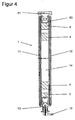
- the anchoring of the sliding barrel device 6 in the sash is shown in detail in FIG. 4 in conjunction with FIG. 5 and is described in the following section.
- the sliding sash 1 is driven by a motor drive 3.
- the one via an output shaft, not shown, via a deflection roller 34 drives rotating toothed belt, on which the sliding sash 1 via driver 33 is coupled.
- the driver 33 is like the sliding barrel device 6 anchored within the upper edge of the wing in the edge closure element 5 or alternatively connected to the hanger 61.
- the electromotive Drive 3 has an electrical control device, not shown, which is attached to the drive profile 31 in the same way as the motor drive 3 can be.
- the motor drive 3 is a So-called automatic drive, the control sensors, not shown is controlled in the area of the passage opening 16.
- All drive units including the drive profile 31 are with a common cover 37 covered to the visible side.
- the covers Cover 37 also the upper edge of the sliding sash 1, the upper edge including suspension device 61 in the overall cuboid sliding door drive 3 engages and is thus arranged concealed.
- the drive profile 31 and the drive devices attached to it are over an adapter profile 36 with a bolt 22 as a horizontal support element or screwed directly to a building wall 2.
- it can also be sliding wing 1 for one act manually operated sliding door, in which the sliding sash 1 also performed with a sliding device 6 in a drive profile 31 are, but which are not a drive motor 32 or other drive device having.
- the sliding sash 1 formed by two parallel glass panes 11, 12, which are usually by one circumferential spacer 4 connected to each other via adhesive connections are.
- the edge closure element 5 is a short distance from the circumferential Spacer 4 further outside and parallel to this between the two disks 11, 12 arranged. It lies flat against the disks 11, 12 and is glued or screwed to them.
- the edge closure element 5 closes approximately flush with the glass panes 11, 12 and has an outward Longitudinal groove 53 for receiving the sliding barrel device 6.
- the edge closure element 5 can be used as a supporting element with a supporting function, e.g.
- edge closure element 5 in the area the upper edge of the wing, or as a normal edge closure element 5 with non-load-bearing Function, e.g. in the area of the vertical wing edges.
- edge closure element in any case it is a support and / or edge closure element can act.
- Figure 3 shows a section along line III - III in Figure 1 in a horizontal plane at about half the height of the wing 1.
- the two sliding wings 1 are shown in the closed position.
- the passage area 16 is delimited by two lateral posts 23, which connect directly to the respective building wall 2.
- a hollow profile 24 On the wing 1 facing post side is a hollow profile 24 with fastening screws 26 screwed.
- the hollow profile 24 is used to hold a not shown Sensor bar or a light barrier, which monitors the passage area 16.
- the two glass panes 11, 12 of the wing 1 in Figure 3 are encircling Spacers 4 connected to each other, through which a formed as a cavity Wing interior 14 is created.
- the spacer 4 can be conventional be formed and have a cavity for receiving Desiccant. It is arranged all around and closes one hermitically completed interior 14 between the panes.
- the spacer 4 is not placed directly on the outside of the wing, but is one piece at a time offset to wing interior 14. In the space created in this way on the Wing outside is parallel to the spacer 4 with a small distance an edge closure element in FIG. 3 along both vertical wing edges 5 arranged for receiving a functional component.
- the edge closure element 5 has an undercut longitudinal groove open towards the outer edge of the wing 53 into which the functional components are inserted or clipped.
- FIG. 19 shows a detailed illustration of the seal 71.
- a profile strip preferably a metal profile, trained stop 72 as a functional component 7 in the edge closure element 5 added.
- the stop 72 is from the open face of the Edge closure element 5 inserted into the longitudinal groove 53 and with not shown Clamping screws 61d secured.
- the stop 72 acts during the closing movement of the wing 1 together with an elastic buffer 25, which in corresponding position of the hollow profile 24 is arranged on the post 23. Thereby is a hard collision of the wings 1 during their closing movement avoided.
- the stop 72 is shown in detail in FIG.
- the carrying or edge closure element 5 can form part of the wing suspension 61 or can be connected to the wing suspension 61.
- the horizontal edge closure element 5, like the vertical edge closure element in FIG. 3, is designed as a profile part with an undercut longitudinal groove 53. It is arranged at a short distance from the circumferential spacer 4 and parallel to it between the two disks 11, 12. It lies flat against the disks 11, 12 and is glued to them.
- the edge closure element 5 is approximately flush with the glass panes 11, 12, the longitudinal groove 53 facing the outer edge of the wing 1.
- the edge closure element 5 can also be screwed to the disks 11, 12 or can engage in them in a form-fitting manner.
- a bow-shaped suspension device 61 engages in the area of the upper edge of the wing of the sliding wing 1 in the carrying and / or edge closure element 5 and is anchored there.
- the suspension device 61 is part of the sliding device 6 and is with the roller carriage 63 via a screw, not shown connected. If necessary, the height adjustment can be made using the threaded screw of the sliding sash 1 are made. In addition, a facility for Transverse adjustment of the sliding leaf 1 may be provided.
- the edge closure element 5 is a receptacle for a height-adjustable cover strip 73 is formed, which in a floor guide 15 engages.
- a sealing brush 73b in the end strip 73 arranged.
- the end bar 73 is shown in detail.
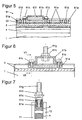
- FIG. 5 shows the bow-shaped suspension device 61 in detail in a section within the wing plane.
- a bearing plate 61a is inserted from the vertical wing edge into the undercut longitudinal groove 53 of the upper support and / or edge closure element 5.
- a support bracket 61b is screwed onto the bearing plate 61a by means of two fastening screws 61c which pass through holes in the bracket and are screwed into threaded holes in the bearing plate.
- the bearing plate 61a is then fixed in the desired position along the upper wing edge by two clamping screws 61d.
- the handle 61b has a lateral receiving slot 61f with which it is suspended on a threaded screw, not shown, which engages in the roller carriage 63, the handle 61b rests on the screw head and is fixed in this position with a lock nut.
- the bearing plate 61a has two further bores 61e, in which a driver bracket for coupling wing 1 and drive 3 as shown in Figure 2 can be attached.
- Figure 6 shows a modified embodiment of the wing suspension in the area of the upper edge of the wing.
- a bearing plate 61a is inserted into an undercut longitudinal groove 53 in the edge closure element 5 and a carrying bracket 61b is fastened to the upper side thereof by means of a screw connection 61c.
- the longitudinal edges of the longitudinal groove 53 are clamped between the bearing plate 61a and the carrying bracket 61b.
- the suspension device 61 is thus also fixed in the area of the upper edge of the wing.
- Separate clamping screws 61d as in FIG. 5 can be omitted.
- Figure 6 and the sectional view in Figure 7 also show the threaded screw 61g, on the head of the handle 61b is suspended and secured with a lock nut 61h.
- FIG. 8 shows an alternative exemplary embodiment of a sliding wing 1 with a sliding carriage which is guided in a carriage profile 31 by roller carriages 63.
- the roller carriages 63 are connected with vertically downwardly projecting threaded screws 61g which engage directly in threaded bores 52 within the edge closure element 5.
- the edge closure element 5 has a larger vertical extension with a relatively long threaded hole compared to the previous embodiments in order to achieve a relatively large adjustment range when adjusting the height of the wing.
- the edge closure element 5 is arranged directly above the spacer 4. By turning the threaded screws 61g, they engage more or less far in the edge closure element 5, as a result of which the wing 1 is raised or lowered. There is no separate handle.
- FIG. 9 shows a section along line IX-IX in FIG. 8 cut in the region of the threaded screw 61g.
- a larger adjustment range is obtained if the spacer 4 is arranged at a distance from the edge closure element 5 and the threaded hole is relatively long or is designed as a through hole.
- the Disks 11, 12 and the running rail 31 on the front sides at least partially reach over, so that the running rail 31 into the receiving groove of the edge closure element 5 dips.
- the one front of the disk 11, 12 can also reach as far as that with its horizontal edge to the lower edge of the Running rail 31 is sufficient, or at least partially the front of the running rail 31 overlaps.
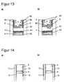
- the carrying and / or edge closure element 5 are each formed in two parts.
- Each of the two parts is connected separately to the respective pane 11, 12 by means of an adhesive bond 42, the two parts engaging in a form-fitting manner for stabilization.
- the interlocking takes place in Figure 13a by a simple longitudinal edge 5d and in Figure 13b by a T-groove 5e in one part and a complementary design in the other part.
- the spacer 4 is also connected to both disks 11, 12 by an adhesive 42.
- a sealing compound 41 is introduced into the space between the spacer 4 and the edge closure element 5.
- a visual protection 13 is provided in the outer pane area, which runs in the edge area of the pane 11, 12 as a visible strip. It can be designed as a separate coating, for. B. in the form of a glued strip or a film or by colored tinting or surface treatment of the pane 11, 12, for. B. etch; steam blasting, branding, grinding.
- the coating 13 or surface treatment can be carried out on the inside of the disks 11, 12, as shown in FIG. 14a, and on the outside of the disks 11, 12, as shown in FIG. 14b.
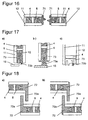
- an elastic seal 71 is accommodated as a functional component 7 in a longitudinal groove 53 of the vertical edge closure element 5 of two wings 1 running against one another.
- the seals 71 in the opposite wing edges have a sinusoidally shaped sealing surface 71a and are designed to be complementary to one another, so that good toothing and thus a good sealing effect result.
- the sealing surfaces overlap the outer edges of the pane so that they are protected against damage.
- FIG. 17 shows a sealing strip 73 as a functional component in an edge sealing element 5 in the area of the floor guide 15.
- the floor guide 15 engages with a vertical leg in a groove within the sealing strip 73.
- a sealing brush 73b is arranged on the underside of the end strip 73.
- a vertical leg of the floor guide 15 engages between two elastic legs 73a running on the underside of the strip in the longitudinal direction the end bar 73 a.
- the two elastic legs 73a meet here at the same time a sealing function.
- Figure 17c corresponds to the embodiment in Figure 17a, with the edge closure element 5 itself is designed as an end strip 73.
- FIG. 18 shows two exemplary embodiments in which a stop 72 is received as a functional component 7 in an edge closure element 5.
- one leg 72a of the stop 72 projects transversely to the wing plane on one side beyond the latter.
- An opposite second wing for example fixed field wing, likewise has such a stop 72, as shown in FIG. 35, with a leg 72a projecting beyond the disk 11, 12, the two legs 72a facing one another and partially overlapping.
- FIG. 19 shows an exemplary embodiment corresponding to FIG. 16 with a detailed illustration of the seal 71 from FIG. 3.
- the seal 71 has a hollow chamber 71b and is clipped into an undercut longitudinal groove 53 in the edge closure element 5.
- FIG. 20 shows an exemplary embodiment corresponding to FIG. 18 with a detailed representation of the stop 72 from FIG. 3.
- the stop 72 is secured by clamping screws 72b in an undercut longitudinal groove 53 of the edge closure element 5.
- a device for adjusting the height of the sliding sash 1 is arranged in the lower sash edge.
- an edge closure element 5 is likewise arranged between the glass panes 11, 12 in the region of the lower horizontal wing edge.
- the U-shaped edge closure element 5 rests with two vertical legs and on the inside of the glass panes 11, 12, with two projections engaging around the lower edges of the two glass panes 11, 12.
- the end strip 73 surrounds the with two legs 73a pointing downwards Floor guide 15, with an additional sealing brush 73b between the two Legs 73a is arranged.
- the height adjustment of the wing 1 suspended in a running rail is carried out such that the end strip 73 at the desired height from the wing side inserted into the lower edge of the wing and secured there.
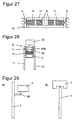
- FIG. 25 An alternative embodiment of the screw connection 51 is shown in FIG. 25 , which also corresponds to the exemplary embodiment in FIGS. 2 to 4.
- the two glass panes 11, 12 are connected to one another by a circumferential spacer 4.
- a support and / or edge closure element 5 is arranged on all edges of the wing 1.
- a sliding mechanism and the wing suspension are anchored in the upper horizontal edge sealing element 5, as shown in FIG. 5, a seal 71 is clipped into the left vertical edge sealing element 5, as shown in FIG. 19, and a stop is shown in the right vertical edge sealing element 5, as shown in FIG 72 is fastened by clamping screws 61d and, as shown in FIG. 21, a sealing strip 73 is inserted in the lower horizontal edge sealing element 5.
- the horizontal and vertical edge closure elements 5 are connected to one another at their corner points by a screw connection 51.
- the screw connection 51 engages with a screw through a transverse bore 5h in the horizontal edge closure elements 5 into a longitudinal bore 5g of the vertical edge closure elements 5 shown in FIGS. 18 and 19. In this way, all edge termination elements 5 are connected to one another by a total of four screws 51 and thus form a solid frame.
- FIG. 27 shows an embodiment of a wing 1 with a support and / or edge closure element 5, which is designed as a vertical guide for a vertically displaceable wing 1.
- a sliding running device 6 for example a guide lug, engages in a longitudinal groove of the edge closure element 5 designed as a guide rail on both vertical wing edges.
- FIG. 28 shows an alternative exemplary embodiment, in which the edge closure element 5 is designed as a running rail for a roller carriage 63.
- a sliding device 6 is fixed in place on a support profile 22 above the wing 1.
- the sliding running device 6 engages with a plurality of roller carriages 63 which are arranged one behind the other in a stationary manner and in which rollers 63b are mounted on both sides, from above into the running rail or the edge closure element 5.
- the wing 1 is thus suspended on the rollers 63b and is slidably guided there in the axial direction.
- FIG. 29 shows two exemplary embodiments of a sliding leaf 1 moved by a drive 3.
- the drive 3 is arranged on the side of the leaf 1 and is coupled to the leaf 1 via an angled output member 38
- FIG. 29 b shows the embodiment in FIGS. 2 to 4 corresponds, the upper edge of the wing engaging in the drive housing 3.
- a locking device 76 can also be accommodated in the carrying and / or edge closure element 5, as shown in FIG. 30 .
- the locking device 76 has a locking bolt 76a which engages in a locking plate, not shown, which can be arranged in a stationary manner or in an adjacent wing 1.
- the wing 1 has a spacer 4 and a carrying and / or edge closure element 5, in which the locking mechanism 76 is integrated.
- FIG. 31 shows a wing 1 corresponding to FIG. 30, a drive 3 being arranged in the carrying and / or edge closure element 5, for. B. designed as an automatic door drive or mechanical door drive, the drive 3 having a preferably linear output member 38, such as a push rod, which is supported on a stationary stop 39.
- a linear output member 38 such as a push rod
- Figure 34 shows an alternative embodiment of a two-leaf sliding door system, which is constructed similarly to the system in Figure 1.
- the sliding leaf 1 are designed as a frameless all-glass leaf.
- a fixed field wing 17 is arranged next to each sliding wing 1, which is also designed as a frameless all-glass wing.
- the fixed field wing 17, like the sliding wing 1, has a spacer 4 which runs all around in the edge region of the pane 11, 12.
- edge closure elements 5 are arranged along the wing edges.
- the upper horizontal edge closure element 5 of the fixed field wing 17 serves to accommodate a clamping device, not shown, with which the fixed field wing 17 is fastened to the bolt 22 above or the adapter profile 36 in FIG.
- FIG. 35 shows a section along line BB in FIG. 34 in a horizontal plane at about half the height of the wing 1.
- the two sliding wings 1 are shown in the closed position.
- a hollow profile 24 In an undercut longitudinal groove 53 facing toward the passage area 16 vertical edge closure element 5 of the fixed field wing 17 is a hollow profile 24 attached with clamping screws, not shown.
- the hollow profile 24 serves the inclusion of a light barrier 94 which monitors the passage area 16 and is designed like the hollow profile 24 in FIG. 3.
- the fixed field wing 17 and the sliding wing 1 are constructed accordingly, as the sliding sash 1 already described in the exemplary embodiment in FIG. 3
- the two glass panes 11, 12 of the wing 1 in FIG. 35 are encircled by one Spacers 4 connected to each other, through which a formed as a cavity Wing interior 14 is created.
- the spacer 4 can be conventional be formed and have a cavity for receiving Desiccant. It is arranged all around and hermetically closes one completed interior 14 between the panes.
- the spacer 4 is not placed directly on the outside of the wing, but is one piece at a time offset to wing interior 14.
- an edge closure element 5 for Recording a functional component or fitting part arranged in the space created in this way on the Wing outside is parallel to the spacer 4 with a small distance this along both vertical wing edges an edge closure element 5 for Recording a functional component or fitting part arranged.
- the edge closure element 5 knows an undercut that is open towards the outer edge of the wing Longitudinal groove 53 into which the functional components or fitting parts are inserted or clipped in.
- a profile strip preferably a metal profile, trained stop 72 as a functional component 7 in the edge shooting element 5 of the sliding sash 1 added.
- the stop 72 is as in FIG. 3 trained and cooperates in the closing movement of the wing 1 an elastic buffer 25 together, which in the appropriate position of the Hollow profile 24 is arranged on the fixed field wing 17.
- edge termination elements 5 of the Sliding wing 1 and / or the fixed field wing 17 may be included. You can be: lighting elements, display elements, control elements such as Push buttons, pressure bar, microswitch, access control, key switch, touch sensitive Foil or the like, displacement sensors, supply lines, Control devices.
- control elements such as Push buttons, pressure bar, microswitch, access control, key switch, touch sensitive Foil or the like, displacement sensors, supply lines, Control devices.
- the power supply can be via a fixed in the drive profile 31 busbar and a sliding contact take place or via an independent power supply, e.g. Battery.
- the support and / or edge closure element instead of just a longitudinal fitting groove also have a plurality of parallel longitudinal grooves for receiving therein Fitting parts or the like to anchor or lead.
- a slot can be special z. B. or the like relatively close to receiving a sealing strip. be trained.
Landscapes
- Engineering & Computer Science (AREA)
- Civil Engineering (AREA)
- Structural Engineering (AREA)
- Mechanical Engineering (AREA)
- Securing Of Glass Panes Or The Like (AREA)
- Specific Sealing Or Ventilating Devices For Doors And Windows (AREA)
- Window Of Vehicle (AREA)
- Seal Device For Vehicle (AREA)
- Power-Operated Mechanisms For Wings (AREA)
- Special Wing (AREA)
Description
- Figur 1
- eine schematische Frontansicht eine Schiebetüranlage;
- Figur 2
- einen Schnitt entlang Linie II - II durch den Schiebetürantrieb in Figur 1;
- Figur 3
- einen Schnitt entlang Linie III- III in horizontaler Richtung durch die Schiebetüranlage in Figur 1;
- Figur 4
- einen Schnitt entlang Linie IV - IV durch den Schiebeflügel in Figur 1;
- Figur 5
- eine Detaildarstellung der Flügelaufhängung in der Flügelebene geschnitten;
- Figur 6
- ein weiteres Ausführungsbeispiel einer Flügelaufhängung;
- Figur 7
- einen Schnitt entlang Linie VII - VII in Figur 6;
- Figur 8
- ein weiteres Ausführungsbeispiel eines Schiebelaufwerks;
- Figur 9
- einen Schnitt entlang Linie IX - IX in Figur 8;
- Figur 13 a) bis b)
- eine Darstellung eines zweiteiligen Randabschlußelements;
- Figur 14 a) bis b)
- eine Sichtblende im Bereich der oberen Flügelkante;
- Figur 16
- eine Darstellung zweier komplementär zueinander ausgebildeter Dichtungen welche als Funktionsbauteil in einem Randabschlußelement aufgenommen sind;
- Figur 17 a) bis c)
- Ausführungen eines Randabschlußelements im Bereich einer Bodenführung;
- Figur 18 a) bis b)
- Ausführungen eines als Schutzleiste ausgeführten Anschlags welcher als Funktionsbauteil in einem Randabschlußelement aufgenommen ist;
- Figur 19
- eine Detaildarstellung einer vertikalen Flügelkante in Figur 3 mit einer Dichtung als Funktionsbauteil;
- Figur 20
- eine Detaildarstellung einer vertikalen Flügelkante in Figur 3 mit einem Anschlag als Funktionsbauteil;
- Figur 21
- eine Detaildarstellung der unteren horizontalen Flügelkante in Figur 4 mit einer Abschlußleiste als Funktionsbauteil im Bereich der Bodenführung;
- Figur 25
- einen Darstellung des Flügels in der Flügelebene geschnitten mit einer Verschraubung der Randabschlußelemente;
- Figur 27
- einen Flügel mit als schienenartige Schiebeführung ausgebildeten Randabschlußelementen;
- Figur 28
- einen Flügel mit einem als Laufschiene ausgebildeten Randabschlußelement in welches eine Schiebelaufeinrichtung mit Rollenwagen eingreift;
- Figur 29 a) bis b)
- zwei mögliche Anordnungen eines Laufwerksprofils gegenüber dem Flügel;
- Figur 30
- eine Frontansicht eines Flügels mit einer in dem Randabschlußelement integrierten Verriegelung;
- Figur 31
- eine Frontansicht eines Flügels mit einer in dem Randabschlußelement integrierten Antriebsvorrichtung mit Schubstange;
- Figur 34
- eine schematische Frontansicht eine Schiebetüranlage mit Festfeldflügeln;
- Figur 35
- einen Schnitt entlang Linie B - B in horizontaler Richtung durch die Schiebetüranlage in Figur 34.
Claims (29)
- Schiebetüranlage mit einem Flügel (1), mit zumindest zwei Scheiben (11, 12) aus Glas, mit einem im Randbereich des Flügels angeordneten Trage- und/oder Randabschlusselement (5), welches von mindestens einer der Scheiben in Blickrichtung senkrecht auf die Flügelebene zumindest teilweise überlappt wird,
wobei ein Abstandhalter (4) vorgesehen ist, der zwischen den Scheiben (91, 12) an den horizontalen und vertikalen Flügelkanten umlaufend angeordnet ist und einen hermetisch abgeschlossenen Innenraum (14) zwischen den Scheiben (11, 12) einschließt,
und der Abstandhalter (4) und das Trage- und/oder Randabschlusselement (5) separat, vorzugsweise mit Abstand zueinander, ausgebildet oder der Abstandhalter (4) und das Trage- und/oder Randabschlusselement (5) verbunden, ausgebildet sind, dadurch gekennzeichnet, daß
der Flügel (1) über eine Schiebelaufeinrichtung (6) In einem Laufwerksprofil oberhalb des Flügels (1) in horizontaler Richtung verschiebbar geführt ist, und die Schiebelaufeinrichtung (6) ein Verankerungsteil aufweist, welches in das im Bereich der Flügeloberkante angeordnete Trage- und/oder Randabschlusselement (5) zur Aufhängung des Flügels eingreift und darin verankert ist. - Schiebetüranlage mit einem Flügel nach Anspruch 1,
dadurch gekennzeichnet, dass die Schiebelaufeinrichtung (6) ein Rollelement (63) und/oder Gleitelement aufweist. - Schiebetüranlage mit einem Flügel nach Anspruch 2,
dadurch gekennzeichnet, dass das Rollelement (63) einen Rollenwagen aufweist, der mindestens eine in einem Drehlager gelagerte Laufrolle (63b) aufweist, und der mit dem Trage- und/oder Randabschlusselement (5) verbunden ist. - Schiebetüranlage mit einem Flügel nach Anspruch 3,
dadurch gekennzeichnet, dass der Rollenwagen (63) der Schiebelaufeinrichtung (6) ein Verankerungsteil aufweist, welches in das Trageund/oder Randabschlusselement (5) eingreift und dort verankert ist. - Schiebetüranlage mit einem Flügel nach einem der Ansprüche 1 oder 4,
dadurch gekennzeichnet, dass das Verankerungsteil als eine Aufhänge- und Justiereinrichtung (61) für den Flügel (1) ausgebildet ist. - Schiebetüranlage mit einem Flügel nach Anspruch 1,
dadurch gekennzeichnet, dass das Trage- und/oder Randabschlusselement (5) am Flügel (1) an mindestens einer horizontalen oder vertikalen Kante angeordnet ist. - Schiebetüranlage mit einem Flügel nach Anspruch 6,
dadurch gekennzeichnet, dass die horizontalen und vertikalen Trage- und/oder Randabschlusselemente (5) untereinander kraftschlüssig verbunden sind oder aber separat voneinander, ohne gegenseitige Verbindung angeordnet sind. - Schiebetüranlage mit einem Flügel nach Anspruch 1,
dadurch gekennzeichnet, dass das Trage-und/oder Randabschlusselement (5) als Längsprofil ausgebildet ist, wobei eine Längsnut (53) zur Aufnahme des Verankerungsteils der Schiebelaufeinrichtung (6) und/oder zur Aufnahme der Flügelaufhängung (61) und/oder zur Aufnahme von Funktionsbauteilen und/oder zur Aufnahme von Beschlagteilen vorgesehen ist. - Schiebetüranlage mit einem Flügel nach Anspruch 8,
dadurch gekennzeichnet, dass das Verankerungsteil und/oder das Funktionsbauteil und/oder das Beschlagteil durch eine Schraubverbindung in dem Trage- und/oder Randabschlusselement (5) befestigt ist. - Schiebetüranlage mit einem Flügel nach Anspruch 8,
dadurch gekennzeichnet, dass das Verankerungsteil und/oder das Funktionsbauteil und/oder das Beschlagteil durch eine Klemm- oder Rastverbindung in dem Trage- und/oder Randabschlusselement (5) befestigt ist. - Schiebetüranlage mit einem Flügel nach Anspruch 1,
dadurch gekennzeichnet, dass das Trage- und/oder Randabschlusselement (5) zwischen Abstandhalter (4) und Flügelaußenkante angeordnet ist. - Schiebetüranlage mit einem Flügel nach Anspruch 1,
dadurch gekennzeichnet, dass das Trage- und/oder Randabschlusselement (5) in der Position eines herkömmlichen Abstandhalters (4) angeordnet ist, wobei es diesen ersetzt. - Schiebetüranlage mit einem Flügel nach Anspruch 1,
dadurch gekennzeichnet, dass das Trage- und/oder Randabschlusselement (5) In seiner wesentlichen Erstreckung zwischen den Scheiben (11,12) angeordnet ist und von beiden Sichtseiten des Flügels (1) vollständig überlappt bzw. abgedeckt ist. - Schiebetüranlage mit einem Flügel nach Anspruch 1,
dadurch gekennzeichnet, dass das Trage- und/oder Randabschlusselement (5) mit mindestens einer Scheibe (11, 12) des Flügels (1) und/oder mit dem Abstandhalter (4) verbunden ist, z.B. über eine Verklebung (42) und/oder eine Verschraubung und/oder einen Formschluss. - Schiebetüranlage mit einem Flügel nach Anspruch 1,
dadurch gekennzeichnet, dass das Trage- und/oder Randabschlusselement (5) mit einem Funktionsbauteil und/oder Beschlagteil wie z B. Verriegelung, Getriebe, Treibstangensystem, Spannelement, Dichtung, Führung, Sensor, Überwachungseinrichtung, Steuerung, Antrieb, kraftübertragendes Gestänge, Gleitschiene, Beleuchtung, Lichtschranke, Lichtgitter, Drucktaster, Druckleisten, Radar, Temperaturfühler, Helligkeitssensor, Feuchtigkeitssensor, Ansteuersensor, Sicherheitssensoren, Rollen, elektrische Leitungen, Wegerkennungssysteme, Winkelerkennungssysteme, Break-Out-Beschlag, Kommunikationsmodule, Kontrollanzeigen verbunden oder versehen ist. - Schiebetüranlage mit einem Flügel nach Anspruch 6,
dadurch gekennzeichnet, dass die horizontalen und/oder vertikalen Trage- und/oder Randabschlusselemente (5) an unterschiedlichen Kanten identisch ausgebildet sind, jedoch die Aufnahme unterschiedlicher Funktionsbauteile und/oder Beschlagteile vorgesehen ist. - Schiebetüranlage mit einem Flügel nach Anspruch 6,
dadurch gekennzeichnet, dass die horizontalen und/oder vertikalen Trage- und Randabschlusselemente (5) an unterschiedlichen Kanten unterschiedlich ausgebildet sind oder unterschiedliche Funktionen aufweisen, z. B. das Flügelgewicht tragende oder nicht tragende Funktionen. - Schiebetüranlage mit einem Flügel nach Anspruch 1,
dadurch gekennzeichnet, dass das Trage- und/oder Randabschlusselement (5) als Eckverbinder und/oder Glasverbinder ausgebildet ist oder dieser Verbinder mit dem Trage- und/oder Randabschlusselement (5) verbunden Ist. - Schiebetüranlage mit einem Flügel nach Anspruch 1,
dadurch gekennzeichnet, dass das Trage- und/oder Randabschlusselement (5) als Teil einer Bodenführung (15) ausgebildet ist, vorzugsweise die Bodenführung (15) aufnimmt. - Schiebetüranlage mit einem Flügel nach Anspruch 1,
dadurch gekennzeichnet, dass das Trage- und/oder Randabschlusselement (5) eins Dichtfunktion erfüllt, wobei vorzugsweise eine Dichtung (71) als Funktionsbauteil in dem Trage- und/oder Randabschlusselement (5) aufgenommen ist. - Schiebetüranlage mit einem Flügel nach Anspruch 1,
dadurch gekennzeichnet, dass das Trage- und/oder Randabschlusselement (5) des Flügels (1) auf Stoß mit einer benachbarten Baueinheit, z.B. einem benachbarten Flügel (1), angeordnet ist, wobei vorzugsweise vorgesehen ist, dass es den Flügel (1) mit der benachbarten Baueinheit verbindet und/oder mit der benachbarten Baueinheit koppelt. - Schiebetüranlage mit einem Flügel nach Anspruch 1,
dadurch gekennzeichnet, dass das Trage- undloder Randabschlusselement (5) mehrteilig ausgebildet ist, und das eins Teil mit der einen Scheibe (11) und das andere Teil mit der anderen Scheibe (12) verbunden ist. - Schiebetüranlage mit einem Flügel nach Anspruch 1,
dadurch gekennzeichnet, dass die Scheiben (11,12) an den aneinander zugewandten innenseiten und/oder an den Außenseiten mit einem Sichtschutz, z.B. einer Bedruckung, einer Beschichtung in Form eines aufgeklebten Streifens oder einer Folie, oder einer farbigen Tönung oder einer Oberfiächenbehandlung, versehen sind. - Schiebetüranlage mit einem Flügel nach Anspruch 1,
dadurch gekennzeichnet, dass das Trage-und/oder Randabschlusselement (5) elastisch und/oder plastisch verformbar oder aus gelenkig miteinander verbundenen Teilen ausgebildet ist. - Schiebetüranlage mit einem Flügel nach Anspruch 1,
dadurch gekennzeichnet, dass der Flügel (1) mit einem Antrieb (3) verbunden ist, z.B. einem mechanischen Antrieb wie einer Feder, oder einem automatischen Antrieb wie einem elektromechanischen Antrieb oder einem elektrohydraullschen Antrieb, wobei vorgesehen ist, dass der Antrieb (3) mit dem Trageund/oder Randabschlusselement (5) verbunden ist, z.B. mit der Schiebelaufeinrichtung (6) oder über ein in dem Trage- und/oder Randabschlusselement (5) abgestütztes oder geführten kraftübertragenden Gestänge, oder dass der Antrieb (3) als integriertes Bauteil des Trage- und/oder Randabschlusselements (5) ausgebildet ist, oder dass der Antrieb (3) an Stelle des Trage- und/oder Randabschlusselements (5) angeordnet ist. - Schiebetüranlage mit einem Flügel nach Anspruch 1,
dadurch gekennzeichnet, dass die Schiebetüranlage einen Festfeldflügel (17) umfasst, der über eine Befestigungseinrichtung in dem Trageund/oder Randabschlusselement (5) verankert ist. - Schiebetüranlage mit einem Flügel nach Anspruch 1,
dadurch gekennzeichnet, dass die Schiebelaufeinrichtung (6) mit einer ortsfesten Laufschiene zusammenwirkt. - Schiebetüranlage nach Anspruch 27,
dadurch gekennzeichnet, dass eine elektrische Einrichtung, zB. Lichtschranke, Sensor, Alarmanlage, elektrische Steuerung, in dem Schiebeflügel (1) und/oder einem Festfeldflügel (17) in das Trage- und/oder Randabschlusselement eingreifend angeordnet ist. - Schiebetüranlage nach Anspruch 27,
dadurch gekennzeichnet, dass die Unterkante des Gehäuses (3, 37) eines motorischen Antriebs und/oder die Unterkante des Gehäuses der Laufschiene (31) bündig mit der Oberkante des Schiebeflügels (1) bzw. des Festfeldflügels (17) abschließt, oder dass die Flügeloberkante in das Gehäuse (3, 37) des Antriebs und/oder in das Gehäuse der Laufschiene (31) eingreift oder dieses Gehäuse hintergreift.
Applications Claiming Priority (8)
| Application Number | Priority Date | Filing Date | Title |
|---|---|---|---|
| DE19631051 | 1996-08-01 | ||
| DE19631051 | 1996-08-01 | ||
| DE19637136 | 1996-09-12 | ||
| DE19637136 | 1996-09-12 | ||
| DE19651331 | 1996-12-11 | ||
| DE19651331 | 1996-12-11 | ||
| DE19700852 | 1997-01-13 | ||
| DE19700852 | 1997-01-13 |
Publications (3)
| Publication Number | Publication Date |
|---|---|
| EP0822310A2 EP0822310A2 (de) | 1998-02-04 |
| EP0822310A3 EP0822310A3 (de) | 1999-03-24 |
| EP0822310B1 true EP0822310B1 (de) | 2003-06-04 |
Family
ID=27438407
Family Applications (1)
| Application Number | Title | Priority Date | Filing Date |
|---|---|---|---|
| EP97113347A Expired - Lifetime EP0822310B1 (de) | 1996-08-01 | 1997-08-01 | Schiebetüranlage |
Country Status (3)
| Country | Link |
|---|---|
| EP (1) | EP0822310B1 (de) |
| AT (1) | ATE242403T1 (de) |
| DE (3) | DE59710198D1 (de) |
Cited By (2)
| Publication number | Priority date | Publication date | Assignee | Title |
|---|---|---|---|---|
| DE202016000526U1 (de) | 2016-01-28 | 2016-03-07 | Gröbmiller GmbH & Co. KG | Schiebetüre und Flügel dafür |
| WO2019138064A1 (en) | 2018-01-12 | 2019-07-18 | Agc Glass Europe | Openable glass structure with protection profiles |
Families Citing this family (27)
| Publication number | Priority date | Publication date | Assignee | Title |
|---|---|---|---|---|
| EP0969176B1 (de) * | 1998-07-03 | 2004-06-09 | GEZE GmbH | Rahmenloser Glasflügel als beweglich gelagerter oder ortsfester Flügel einer Tür, eines Fensters oder einer Fassade oder Glaswand |
| AU1211501A (en) * | 1999-10-19 | 2001-04-30 | Stanley Works Pty. Ltd., The | Automatic door assembly with an on-board display device |
| DE10016144A1 (de) * | 2000-03-31 | 2001-10-04 | Volkswagen Ag | Vorrichtung zum Justieren einer Baugruppe, insbesondere einer Instrumententafel eines Kraftfahrzeuges |
| DE10119640C2 (de) * | 2001-04-20 | 2003-12-24 | Geze Gmbh | Rahmenlose Trennwand |
| DE10151755A1 (de) | 2001-10-19 | 2003-07-17 | Geze Gmbh | Verbindungselement für eine Glastrennwand |
| DE10259924B4 (de) * | 2002-12-20 | 2008-04-30 | Geze Gmbh | Schiebetüranlage |
| DE202004017100U1 (de) * | 2004-10-29 | 2005-03-03 | Gretsch-Unitas GmbH Baubeschläge | Beschlag für eine Hebe-Schiebe-Tür |
| DE102007059222A1 (de) * | 2007-12-07 | 2009-07-30 | Raumplus Gmbh & Co. Kg | Wand-, Tür- oder Fensterelement |
| EP2233674B1 (de) * | 2009-03-26 | 2014-08-06 | Rodolphe Weibel | Verglaste Öffnung in einem Bauwerk |
| DE202011100577U1 (de) * | 2011-05-12 | 2012-08-13 | Grass Gmbh | Möbelbeschlag für ein bewegbares Möbelteil und Möbel |
| BE1021561B1 (nl) * | 2013-01-10 | 2015-12-14 | Reynaers Aluminium,Naamloze Vennootschap | Vleugel van een schuifraam of schuifdeur en werkwijze om een dergelijke vleugel te voorzien van een sluitplaat |
| EP3002402A1 (de) * | 2014-09-30 | 2016-04-06 | AGC Glass Europe | Öffnungsfähige rahmenlose Tür- oder Fensterrahmenanordnung mit Isolierverglasung |
| FR3035427B1 (fr) * | 2015-04-21 | 2021-05-21 | Souchier | Vitrage, profile adapte au vitrage et ouvrant comprenant un tel vitrage |
| ES2589835B1 (es) * | 2015-05-15 | 2017-09-07 | Cabañero, S.L. | Cerramiento practicable inteligente |
| CN105672827B (zh) * | 2016-03-04 | 2017-09-19 | 江汉大学 | 一种窗户 |
| CN105863482A (zh) * | 2016-06-08 | 2016-08-17 | 青岛威奥轨道装饰材料制造有限公司 | 一种轨道车辆用双开自动门系统 |
| CN105971468B (zh) * | 2016-06-14 | 2018-08-14 | 青岛威奥轨道股份有限公司 | 一种轨道车辆用自动门系统 |
| CA2947994A1 (fr) | 2016-11-08 | 2018-05-08 | Portes Patio Novatech Inc. | Dispositif de serrage de cadres thermiquement efficaces |
| ES2688170B1 (es) | 2017-03-31 | 2019-07-09 | Cabanero S L | Cerramiento deslizante inteligente anti-intrusión |
| ES2694598B1 (es) | 2017-03-31 | 2019-07-09 | Cabanero S L | Sistema y método de cierre motorizado |
| DE102018103724B4 (de) | 2018-02-20 | 2020-04-02 | Griffwerk GmbH | Schiebetüranlage mit verbesserter Stromzufuhr |
| GB201806598D0 (en) * | 2018-04-23 | 2018-06-06 | Monaghan John | Slide opening door assembly |
| CN108590436A (zh) * | 2018-04-25 | 2018-09-28 | 未石互动科技股份有限公司 | 一种投影移门装置 |
| BE1027106B1 (nl) * | 2019-07-29 | 2020-10-02 | Lootens Evolis Bvpa | Glasafstandhouder voor een regelbaar schuifdeursysteem |
| DE102020203079A1 (de) | 2020-03-11 | 2021-09-16 | Geze Gmbh | Schiebetüranlage sowie verfahren zum öffnen einer schiebetüranlage |
| CH718059B1 (de) | 2021-12-14 | 2022-07-29 | Gilgen Door Systems Ag | Aufhänganordnung für eine Schiebetür. |
| DE102023102026A1 (de) | 2023-01-27 | 2024-08-01 | Solarlux Gmbh | Schiebeflügelsystem |
Family Cites Families (14)
| Publication number | Priority date | Publication date | Assignee | Title |
|---|---|---|---|---|
| BE533415A (de) * | ||||
| US3359573A (en) * | 1964-11-12 | 1967-12-26 | Ralph T Casebolt | Glass shower enclosure door |
| US3425163A (en) * | 1966-11-14 | 1969-02-04 | Ppg Industries Inc | Preglazed sliding panel |
| CH631780A5 (de) * | 1981-06-09 | 1982-08-31 | Jaggi Matthias Planet | Dichtungsanordnung an einer schwellenlosen tuer. |
| US4574860A (en) * | 1984-05-31 | 1986-03-11 | Otto Weiss | Adjustable storm garage door |
| FR2572766A1 (fr) * | 1984-11-08 | 1986-05-09 | Juillet Hubert | Double vitrage a cadre interieur autoportant |
| DE3540346C1 (de) * | 1985-11-14 | 1987-06-19 | Fuhr Carl Gmbh & Co | In Form eines Fensters,Tuere oder dergleichen ausgebildeter Schiebefluegel |
| DE3837813A1 (de) * | 1988-11-08 | 1990-05-10 | Alois Heiler | Duschtrennwand |
| DE4011200A1 (de) * | 1989-05-06 | 1990-11-08 | Jost Profil System Gmbh | Abdichtvorrichtung fuer fluegel von tueren oder fenstern u. dgl. |
| DE4032604C2 (de) * | 1990-10-15 | 2000-01-27 | Geze Gmbh & Co | Schiebetüranlage mit wenigstens einem schieb- und schwenkbaren Türflügel |
| DE4130149C2 (de) * | 1991-07-27 | 1998-07-23 | Joseph Fischl | Fensterflügel sowie unter Verwendung dieses Flügels ausgebildetes Fenster |
| ATE166943T1 (de) * | 1993-01-21 | 1998-06-15 | Pilkington Uk Ltd | Gerahmte verglasungseinheit |
| DE4400196C1 (de) * | 1994-01-05 | 1995-06-29 | Temotrans Bv | Glastür |
| DE9418989U1 (de) * | 1994-11-25 | 1995-02-16 | Holz + Design GmbH, 81673 München | Beleuchtbare Schiebetür |
-
1997
- 1997-08-01 AT AT97113347T patent/ATE242403T1/de active
- 1997-08-01 DE DE59710198T patent/DE59710198D1/de not_active Expired - Lifetime
- 1997-08-01 EP EP97113347A patent/EP0822310B1/de not_active Expired - Lifetime
- 1997-08-01 DE DE19733367A patent/DE19733367B4/de not_active Expired - Lifetime
- 1997-08-01 DE DE19733366A patent/DE19733366A1/de not_active Withdrawn
Cited By (2)
| Publication number | Priority date | Publication date | Assignee | Title |
|---|---|---|---|---|
| DE202016000526U1 (de) | 2016-01-28 | 2016-03-07 | Gröbmiller GmbH & Co. KG | Schiebetüre und Flügel dafür |
| WO2019138064A1 (en) | 2018-01-12 | 2019-07-18 | Agc Glass Europe | Openable glass structure with protection profiles |
Also Published As
| Publication number | Publication date |
|---|---|
| DE19733367B4 (de) | 2006-10-19 |
| ATE242403T1 (de) | 2003-06-15 |
| DE19733367A1 (de) | 1998-06-18 |
| EP0822310A2 (de) | 1998-02-04 |
| DE59710198D1 (de) | 2003-07-10 |
| EP0822310A3 (de) | 1999-03-24 |
| DE19733366A1 (de) | 1998-02-12 |
Similar Documents
| Publication | Publication Date | Title |
|---|---|---|
| DE19733393B4 (de) | Glasflügel, insbesondere für Türen, Fenster, Festfelder oder als Fassadenelement | |
| EP0822310A2 (de) | Flügel einer Tür, eines Fensters oder dergleichen | |
| DE19634390C2 (de) | Bodenverankerung für Flügel einer ortsveränderbaren Schiebeflügelwand | |
| DE69224663T2 (de) | Fenster mit einem rahmen aus extrudierten profilen | |
| EP3306020A1 (de) | Vorrichtung für das verschliessen einer gebäudeöffnung | |
| EP0658662B1 (de) | Glasfassade mit Fenster | |
| DE19943041A1 (de) | Gebäudeausgangsvorrichtung | |
| EP0969176B1 (de) | Rahmenloser Glasflügel als beweglich gelagerter oder ortsfester Flügel einer Tür, eines Fensters oder einer Fassade oder Glaswand | |
| DE19753132A1 (de) | Brandschutzschiebetüranlage | |
| DE29724242U1 (de) | Flügel für ein Fenster, eine Tür o.dgl. sowie Trage- und/oder Randabschlußelement für einen Flügel | |
| DE19809909B4 (de) | Schiene mit Stromzuführungseinrichtung | |
| EP0798441B1 (de) | Brandschutzschiebetüranlage | |
| EP0845566A2 (de) | Flügeleinheit | |
| WO2002063123A1 (de) | Verschluss -und scharniersystem und -vorrichtung | |
| DE10038866A1 (de) | Automatische Schiebetüranlage mit Notöffnungsvorrichtung | |
| DE19901753A1 (de) | Rahmenloser Glasflügel einer Tür oder eines Fensters | |
| DE19717959A1 (de) | Vorrichtung zum Öffnen, Schließen oder Dämpfen eines Flügels einer Tür, eines Fensters oder dergleichen | |
| AT527101A1 (de) | Anordnung aus einer Antriebsvorrichtung, einem Bauteil zum Verschließen einer Öffnung und einer Führungseinrichtung | |
| DE10231841A1 (de) | Schiebetür | |
| DE10107471A1 (de) | Verwendung eines Mehrgelenkscharniers in einer Vitrine und Vitrine | |
| DE102004011878A1 (de) | Fenster oder Tür | |
| EP2204525A2 (de) | Schiebe-Drehtür für Brandschutzzwecke | |
| GR3000759T3 (en) | Espagnolette for doors or windows | |
| DE102007030386A1 (de) | Antrieb für eine Tür oder ein Fenster | |
| EP1503025A2 (de) | Schiebekonstruktion für Fenster oder Türen |
Legal Events
| Date | Code | Title | Description |
|---|---|---|---|
| PUAI | Public reference made under article 153(3) epc to a published international application that has entered the european phase |
Free format text: ORIGINAL CODE: 0009012 |
|
| AK | Designated contracting states |
Kind code of ref document: A2 Designated state(s): AT BE CH DE DK ES FI FR GB GR IE IT LI LU MC NL PT SE |
|
| AX | Request for extension of the european patent |
Free format text: AL PAYMENT 970823;LT PAYMENT 970823;LV PAYMENT 970823;RO PAYMENT 970823;SI PAYMENT 970823 |
|
| PUAL | Search report despatched |
Free format text: ORIGINAL CODE: 0009013 |
|
| AK | Designated contracting states |
Kind code of ref document: A3 Designated state(s): AT BE CH DE DK ES FI FR GB GR IE IT LI LU MC NL PT SE |
|
| AX | Request for extension of the european patent |
Free format text: AL PAYMENT 970823;LT PAYMENT 970823;LV PAYMENT 970823;RO PAYMENT 970823;SI PAYMENT 970823 |
|
| 17P | Request for examination filed |
Effective date: 19990626 |
|
| RAP1 | Party data changed (applicant data changed or rights of an application transferred) |
Owner name: GEZE GMBH |
|
| AKX | Designation fees paid |
Free format text: AT BE CH DE DK ES FI FR GB GR IE IT LI LU MC NL PT SE |
|
| AXX | Extension fees paid |
Free format text: AL PAYMENT 19970823;LT PAYMENT 19970823;LV PAYMENT 19970823;RO PAYMENT 19970823;SI PAYMENT 19970823 |
|
| RAP3 | Party data changed (applicant data changed or rights of an application transferred) |
Owner name: GEZE GMBH |
|
| RIN1 | Information on inventor provided before grant (corrected) |
Inventor name: METTENLEITER, KARL Inventor name: JUENGLING, PETER Inventor name: GMELIN, ANDREAS Inventor name: FISCHBACH, STEFAN |
|
| RAP1 | Party data changed (applicant data changed or rights of an application transferred) |
Owner name: GEZE GLAS DESIGN GMBH |
|
| 17Q | First examination report despatched |
Effective date: 20020612 |
|
| RAP1 | Party data changed (applicant data changed or rights of an application transferred) |
Owner name: GEZE GMBH |
|
| GRAH | Despatch of communication of intention to grant a patent |
Free format text: ORIGINAL CODE: EPIDOS IGRA |
|
| RTI1 | Title (correction) |
Free format text: SLIDING DOOR ASSEMBLY |
|
| GRAH | Despatch of communication of intention to grant a patent |
Free format text: ORIGINAL CODE: EPIDOS IGRA |
|
| GRAA | (expected) grant |
Free format text: ORIGINAL CODE: 0009210 |
|
| AK | Designated contracting states |
Designated state(s): AT BE CH DE DK ES FI FR GB GR IE IT LI LU MC NL PT SE |
|
| AX | Request for extension of the european patent |
Extension state: AL LT LV RO SI |
|
| PG25 | Lapsed in a contracting state [announced via postgrant information from national office to epo] |
Ref country code: IT Free format text: LAPSE BECAUSE OF FAILURE TO SUBMIT A TRANSLATION OF THE DESCRIPTION OR TO PAY THE FEE WITHIN THE PRESCRIBED TIME-LIMIT;WARNING: LAPSES OF ITALIAN PATENTS WITH EFFECTIVE DATE BEFORE 2007 MAY HAVE OCCURRED AT ANY TIME BEFORE 2007. THE CORRECT EFFECTIVE DATE MAY BE DIFFERENT FROM THE ONE RECORDED. Effective date: 20030604 Ref country code: IE Free format text: LAPSE BECAUSE OF FAILURE TO SUBMIT A TRANSLATION OF THE DESCRIPTION OR TO PAY THE FEE WITHIN THE PRESCRIBED TIME-LIMIT Effective date: 20030604 Ref country code: FR Free format text: LAPSE BECAUSE OF NON-PAYMENT OF DUE FEES Effective date: 20030604 Ref country code: FI Free format text: LAPSE BECAUSE OF FAILURE TO SUBMIT A TRANSLATION OF THE DESCRIPTION OR TO PAY THE FEE WITHIN THE PRESCRIBED TIME-LIMIT Effective date: 20030604 |
|
| REG | Reference to a national code |
Ref country code: GB Ref legal event code: FG4D Free format text: NOT ENGLISH |
|
| REG | Reference to a national code |
Ref country code: CH Ref legal event code: NV Representative=s name: DR. LUSUARDI AG Ref country code: CH Ref legal event code: EP |
|
| REG | Reference to a national code |
Ref country code: SE Ref legal event code: TRGR |
|
| GBT | Gb: translation of ep patent filed (gb section 77(6)(a)/1977) | ||
| REG | Reference to a national code |
Ref country code: IE Ref legal event code: FG4D Free format text: GERMAN |
|
| REF | Corresponds to: |
Ref document number: 59710198 Country of ref document: DE Date of ref document: 20030710 Kind code of ref document: P |
|
| PG25 | Lapsed in a contracting state [announced via postgrant information from national office to epo] |
Ref country code: MC Free format text: LAPSE BECAUSE OF NON-PAYMENT OF DUE FEES Effective date: 20030831 |
|
| PG25 | Lapsed in a contracting state [announced via postgrant information from national office to epo] |
Ref country code: PT Free format text: LAPSE BECAUSE OF FAILURE TO SUBMIT A TRANSLATION OF THE DESCRIPTION OR TO PAY THE FEE WITHIN THE PRESCRIBED TIME-LIMIT Effective date: 20030904 Ref country code: GR Free format text: LAPSE BECAUSE OF FAILURE TO SUBMIT A TRANSLATION OF THE DESCRIPTION OR TO PAY THE FEE WITHIN THE PRESCRIBED TIME-LIMIT Effective date: 20030904 Ref country code: DK Free format text: LAPSE BECAUSE OF FAILURE TO SUBMIT A TRANSLATION OF THE DESCRIPTION OR TO PAY THE FEE WITHIN THE PRESCRIBED TIME-LIMIT Effective date: 20030904 |
|
| PG25 | Lapsed in a contracting state [announced via postgrant information from national office to epo] |
Ref country code: ES Free format text: LAPSE BECAUSE OF FAILURE TO SUBMIT A TRANSLATION OF THE DESCRIPTION OR TO PAY THE FEE WITHIN THE PRESCRIBED TIME-LIMIT Effective date: 20030915 |
|
| LTIE | Lt: invalidation of european patent or patent extension |
Effective date: 20030604 |
|
| REG | Reference to a national code |
Ref country code: IE Ref legal event code: FD4D |
|
| PLBE | No opposition filed within time limit |
Free format text: ORIGINAL CODE: 0009261 |
|
| STAA | Information on the status of an ep patent application or granted ep patent |
Free format text: STATUS: NO OPPOSITION FILED WITHIN TIME LIMIT |
|
| 26N | No opposition filed |
Effective date: 20040305 |
|
| EN | Fr: translation not filed | ||
| REG | Reference to a national code |
Ref country code: CH Ref legal event code: PFA Owner name: GEZE GMBH Free format text: GEZE GMBH#REINHOLD-VOESTER-STRASSE 21-29#71229 LEONBERG (DE) -TRANSFER TO- GEZE GMBH#REINHOLD-VOESTER-STRASSE 21-29#71229 LEONBERG (DE) |
|
| PGFP | Annual fee paid to national office [announced via postgrant information from national office to epo] |
Ref country code: LU Payment date: 20150824 Year of fee payment: 19 |
|
| PGFP | Annual fee paid to national office [announced via postgrant information from national office to epo] |
Ref country code: GB Payment date: 20150819 Year of fee payment: 19 |
|
| PGFP | Annual fee paid to national office [announced via postgrant information from national office to epo] |
Ref country code: BE Payment date: 20150819 Year of fee payment: 19 Ref country code: NL Payment date: 20150830 Year of fee payment: 19 Ref country code: SE Payment date: 20150819 Year of fee payment: 19 Ref country code: AT Payment date: 20150820 Year of fee payment: 19 |
|
| PGFP | Annual fee paid to national office [announced via postgrant information from national office to epo] |
Ref country code: CH Payment date: 20160819 Year of fee payment: 20 Ref country code: DE Payment date: 20160831 Year of fee payment: 20 |
|
| PG25 | Lapsed in a contracting state [announced via postgrant information from national office to epo] |
Ref country code: BE Free format text: LAPSE BECAUSE OF NON-PAYMENT OF DUE FEES Effective date: 20160831 |
|
| REG | Reference to a national code |
Ref country code: SE Ref legal event code: EUG |
|
| REG | Reference to a national code |
Ref country code: NL Ref legal event code: MM Effective date: 20160901 |
|
| REG | Reference to a national code |
Ref country code: AT Ref legal event code: MM01 Ref document number: 242403 Country of ref document: AT Kind code of ref document: T Effective date: 20160801 |
|
| GBPC | Gb: european patent ceased through non-payment of renewal fee |
Effective date: 20160801 |
|
| PG25 | Lapsed in a contracting state [announced via postgrant information from national office to epo] |
Ref country code: SE Free format text: LAPSE BECAUSE OF NON-PAYMENT OF DUE FEES Effective date: 20160802 |
|
| PG25 | Lapsed in a contracting state [announced via postgrant information from national office to epo] |
Ref country code: AT Free format text: LAPSE BECAUSE OF NON-PAYMENT OF DUE FEES Effective date: 20160801 |
|
| PG25 | Lapsed in a contracting state [announced via postgrant information from national office to epo] |
Ref country code: NL Free format text: LAPSE BECAUSE OF NON-PAYMENT OF DUE FEES Effective date: 20160901 |
|
| PG25 | Lapsed in a contracting state [announced via postgrant information from national office to epo] |
Ref country code: GB Free format text: LAPSE BECAUSE OF NON-PAYMENT OF DUE FEES Effective date: 20160801 |
|
| REG | Reference to a national code |
Ref country code: DE Ref legal event code: R071 Ref document number: 59710198 Country of ref document: DE |
|
| REG | Reference to a national code |
Ref country code: CH Ref legal event code: PL |
|
| PG25 | Lapsed in a contracting state [announced via postgrant information from national office to epo] |
Ref country code: LU Free format text: LAPSE BECAUSE OF NON-PAYMENT OF DUE FEES Effective date: 20160801 |