EP2204525A2 - Schiebe-Drehtür für Brandschutzzwecke - Google Patents
Schiebe-Drehtür für Brandschutzzwecke Download PDFInfo
- Publication number
- EP2204525A2 EP2204525A2 EP09014881A EP09014881A EP2204525A2 EP 2204525 A2 EP2204525 A2 EP 2204525A2 EP 09014881 A EP09014881 A EP 09014881A EP 09014881 A EP09014881 A EP 09014881A EP 2204525 A2 EP2204525 A2 EP 2204525A2
- Authority
- EP
- European Patent Office
- Prior art keywords
- door
- construction
- revolving
- revolving door
- fire protection
- Prior art date
- Legal status (The legal status is an assumption and is not a legal conclusion. Google has not performed a legal analysis and makes no representation as to the accuracy of the status listed.)
- Granted
Links
- 238000010276 construction Methods 0.000 claims abstract description 44
- 238000007789 sealing Methods 0.000 claims description 20
- 239000007787 solid Substances 0.000 claims description 6
- 238000005192 partition Methods 0.000 claims description 5
- 238000009434 installation Methods 0.000 claims description 4
- 239000002023 wood Substances 0.000 abstract description 8
- 239000000565 sealant Substances 0.000 description 6
- 230000009970 fire resistant effect Effects 0.000 description 4
- 239000000463 material Substances 0.000 description 4
- 239000011521 glass Substances 0.000 description 3
- 230000002093 peripheral effect Effects 0.000 description 3
- 239000005336 safety glass Substances 0.000 description 3
- 229910000831 Steel Inorganic materials 0.000 description 2
- XAGFODPZIPBFFR-UHFFFAOYSA-N aluminium Chemical compound [Al] XAGFODPZIPBFFR-UHFFFAOYSA-N 0.000 description 2
- 229910052782 aluminium Inorganic materials 0.000 description 2
- 239000003795 chemical substances by application Substances 0.000 description 2
- 239000010959 steel Substances 0.000 description 2
- 235000003332 Ilex aquifolium Nutrition 0.000 description 1
- 241000209027 Ilex aquifolium Species 0.000 description 1
- 239000004820 Pressure-sensitive adhesive Substances 0.000 description 1
- 235000004443 Ricinus communis Nutrition 0.000 description 1
- 240000000528 Ricinus communis Species 0.000 description 1
- 239000000853 adhesive Substances 0.000 description 1
- 230000005540 biological transmission Effects 0.000 description 1
- 239000002131 composite material Substances 0.000 description 1
- 238000013016 damping Methods 0.000 description 1
- 239000000725 suspension Substances 0.000 description 1
- 230000007704 transition Effects 0.000 description 1
Images

Classifications
-
- E—FIXED CONSTRUCTIONS
- E06—DOORS, WINDOWS, SHUTTERS, OR ROLLER BLINDS IN GENERAL; LADDERS
- E06B—FIXED OR MOVABLE CLOSURES FOR OPENINGS IN BUILDINGS, VEHICLES, FENCES OR LIKE ENCLOSURES IN GENERAL, e.g. DOORS, WINDOWS, BLINDS, GATES
- E06B3/00—Window sashes, door leaves, or like elements for closing wall or like openings; Layout of fixed or moving closures, e.g. windows in wall or like openings; Features of rigidly-mounted outer frames relating to the mounting of wing frames
- E06B3/32—Arrangements of wings characterised by the manner of movement; Arrangements of movable wings in openings; Features of wings or frames relating solely to the manner of movement of the wing
- E06B3/50—Arrangements of wings characterised by the manner of movement; Arrangements of movable wings in openings; Features of wings or frames relating solely to the manner of movement of the wing with more than one kind of movement
- E06B3/5054—Arrangements of wings characterised by the manner of movement; Arrangements of movable wings in openings; Features of wings or frames relating solely to the manner of movement of the wing with more than one kind of movement where the sliding and rotating movements are independent of each other
- E06B3/5081—Arrangements of wings characterised by the manner of movement; Arrangements of movable wings in openings; Features of wings or frames relating solely to the manner of movement of the wing with more than one kind of movement where the sliding and rotating movements are independent of each other at least two wings have a different kind of movement
-
- E—FIXED CONSTRUCTIONS
- E06—DOORS, WINDOWS, SHUTTERS, OR ROLLER BLINDS IN GENERAL; LADDERS
- E06B—FIXED OR MOVABLE CLOSURES FOR OPENINGS IN BUILDINGS, VEHICLES, FENCES OR LIKE ENCLOSURES IN GENERAL, e.g. DOORS, WINDOWS, BLINDS, GATES
- E06B5/00—Doors, windows, or like closures for special purposes; Border constructions therefor
- E06B5/10—Doors, windows, or like closures for special purposes; Border constructions therefor for protection against air-raid or other war-like action; for other protective purposes
- E06B5/16—Fireproof doors or similar closures; Adaptations of fixed constructions therefor
Definitions
- the present invention relates to a fire protection door construction, which has at least two independently openable wooden door elements, optionally with fire protection windows, and in which at least one of the door elements is designed as a sliding door and at least one as a revolving door.
- Fire doors for installation in fixed fire walls are well known. This is how the German utility model describes DE 298 19 678 U1 a fire protection partition made of glass, in which a single swing door is integrated.
- the door leaf of the revolving door consists of a fire-resistant window enclosed in a wooden frame, which is hinged on a door frame by means of hinges attached to the wooden frame. While such door designs are suitable for passage of people, larger items or vehicles can not be moved through because of the limited doorway cut-outs of these doors.
- the object underlying the invention is to provide a way that allows the passage for both persons and for large items or vehicles and takes into account the limited parking paths of a sliding and revolving door.
- a fire door construction for installation in a fixed fire protection partition, which has at least two independently openable wooden door elements, optionally with fire protection, and at least one of the door elements as a sliding door and at least one as a revolving door is configured, wherein the door construction is characterized in that the sliding and the revolving door are arranged directly next to each other and open in the opposite direction.
- the door construction according to the invention consists of a sliding door and a revolving door.
- the sliding door and revolving door are open in the opposite direction.
- the revolving door is hinged on an outer side of the door construction, for example via door hinges, while the opening mechanism of the sliding door is designed such that it must be moved away from the revolving door in order to open the sliding door.
- hinged doors are mounted in a three-sided door frame, of which the door hinges are attached to a vertical frame part, while on the opposite frame part a strike plate is attached.
- the invention is now based on the finding that can be dispensed with by the structure of the invention on the vertical frame part, since the hinged door facing the edge of a next to the revolving door positioned sliding door take over its function can, without the fire protection properties of the entire door construction are significantly deteriorated.
- both door elements are independent of each other and also because of the smaller size easy to use. So it is possible, for example, only open the sliding door and close or alternatively also the revolving door.
- a practical advantage is also that both doors are more or less in the same place. For example, if it turns out that an item that should pass through the revolving door is too wide for it, the sliding door must only be pushed open until the opening has a sufficient width. It is therefore not necessary to bring the object from the revolving door to a larger door possibly located elsewhere, nor is it necessary to fully open the larger door.
- a closable opening of variable width can be created in a fire protection partition or in another wall.
- Another advantage of the door construction according to the invention is that with this a relatively large door opening can be created, in which the moving parts, ie rotating and sliding door, of their size relative to each other can be adjusted so that they are by hand without much effort open and close.
- the sliding door can also be designed to be electrically operable in a manner known per se or the displaceability can be facilitated by cables.
- the width ratio of the revolving door to the sliding door can be in the range of 1: 1.5 to 1: 2.5, for example.
- the door construction according to the invention also allows the construction of visually homogeneous fire-resistant partitions with fixed fire glass elements, since the revolving door, the sliding door and the fixed fire protection glass elements can be made in the same height if necessary.
- the revolving door has a closing mechanism which engages when the revolving door is closed in a receptacle located in the sliding door.
- a locking mechanism which can be used according to the invention is, for example, a latch which is actuated via a door latch mounted on the revolving door, wherein the latch is pulled out of the receptacle in the sliding door and the revolving door is released in this way.
- the locking mechanism together with the doorknob can be integrated, for example, in a lock housing.
- a development of the door construction according to the invention provides that the revolving door and / or the sliding door each have a single, continuous fire protection pane.
- the door elements may have frame parts or a circumferential frame or a circumferential profile.
- their strength is preferably chosen so that the surface of the continuous fire protection windows is as large as possible, without endangering the stability of the construction.
- As a material for the frame is preferably solid wood used because it changes its carrying capacity only slightly in case of fire.
- other materials that can be used in the fire protection area for frames such as steel, for example.
- the revolving door is designed frameless.
- the door hinges and, where appropriate, the locking mechanism are fastened directly to the fire protection pane of the revolving door.
- a door construction according to this embodiment is characterized by a particularly high light transmission and also has a visually appealing appearance. If the fireproof pane contains toughened safety glass, the openings required to accommodate the closing mechanism and for the hinges will be applied before the safety glass is clamped.
- the sliding door at least on its hinged door facing the abutment edge on a frame part, in which the receptacle is provided for the closing mechanism of the revolving door.
- This frame part may preferably consist of solid wood or another material which can be used in the fire protection area for frames.
- the sliding door with a peripheral frame, preferably made of solid wood. In this way, further components of a sliding door such as floor castors or a suspension can be relatively easily attached.
- a further preferred embodiment of the door construction according to the invention is that the revolving door has a sliding edge facing the sliding door, wherein this abutting edge and the abutting edge of the sliding door are step-like stepped and each have at least two stages. Accordingly, the mutually facing abutting edges of the revolving door and sliding door are stair-stepped each with at least two stages.
- This design of the above-mentioned abutting edges is advantageous because in this way a good seal between the two door elements can be achieved, which is particularly important in case of fire.
- At least one of the stages is provided with a sealing agent in a further preferred manner.
- the sealant also acts as a damping agent when closing the door.
- the mechanical load when slamming the revolving door can be reduced.
- a sealant for example, elongated lip seals into consideration, which either have a self-adhesive pressure-sensitive adhesive strip or on its underside in the profile have a mushroom-like holding profile with which the sealing strip can be snapped into a correspondingly shaped groove in the stage of the door element.
- the sealing means has a crescent-shaped profile on the sealing side. This is particularly advantageous because this form of the sealant on the one hand has good sealing properties and on the other hand ensures that the sliding door when closing against the abutting edge of the revolving door can slide into the sealing seat, without damaging the sealant.
- a sealing means is provided at both stages of the abutting edges.
- the sealing means may either be attached to a door or, alternatively, in such a way that either the first step of the revolving door and the second step of the sliding door or the second step of the revolving door and the first step of the sliding door are provided with a sealing means.
- a step-like gradation on one or both door elements on the other abutting edges.
- This gradation may have either one or two stages, with a step for sealing at the other abutting edges, so with the exception of the abutting edges between the two door elements, is usually sufficient.
- the components which come into contact with these other abutting edges, in which the entire door construction is enclosed, such as frame parts, frame row and the like are similarly shaped stepwise with one, two or more steps.
- the step or steps of the door elements and / or the components which come into contact with them can also be provided with a sealing means.
- the revolving door has an automatic door closer, in particular a pneumatic or hydraulic door closer.
- an automatic door closer in particular a pneumatic or hydraulic door closer.
- a further development of the door construction according to the invention provides that the revolving door has a further locking possibility on the upper and / or lower side.
- This can be realized, for example, by a retractable in the upper and lower abutting edges of the revolving door locking pin, which can engage in a corresponding cylindrical recess in the ground or located above the revolving door camber.
- the secure locking of the revolving door can be ensured even if the sliding door is open and the revolving door thus lacks the fixation by the engagement of its locking mechanism in the recording of the sliding door.
- At least one of the fire protection panes has an intumescent fire protection layer inside or a fire protection gel.
- the use of these fire panels is due to their good fire protection properties at the same time high transparency of advantage.
- the hinges of the revolving door are attached to a wall spar or a feed frame.
- the wall spar or the lining frame are preferably made of solid wood. In this way, the revolving door can be fastened particularly reliable.
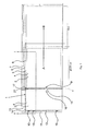
- a fire protection door construction consisting of a sliding door 2 and a revolving door 3, each in closed form A and open form B of the sliding door 2 shown.
- the opening direction of the revolving door 3 is indicated by a dashed arrow.
- the sliding door 2 may be formed as a full-surface wooden door or optionally have a continuous fire protection panel 4, which is enclosed in a circumferential frame 5 made of solid wood and shown in dashed lines in the drawing.
- the fire protection panel 4 consists of two layers of tempered safety glass with a laminated intermediate layer of intumescent material in case of fire.
- the sliding door 2 is held on an upper abutting edge 6 of its peripheral frame 5 on a running rail 7, which is covered by a facing 8, laterally displaceable.
- the encircling frame 5 of the sliding door 2 is equipped for manual opening with a recessed grip 9. During the opening of the sliding door 2, the door is simultaneously lifted slightly by the inclination of the running rail 7.
- the revolving door 3 is frameless made of wood and can optionally have a single continuous fire protection panel 4, which is rotatably supported by three fixed in the fire panel 4 door hinges 10 on a spar 11. In the closed state, the fireproof pane 4 of the revolving door 3 rests against a ramp surface 12 provided on the spar 11 and against a ramp surface 14 provided on a lintel 13.
- the revolving door 3 is provided on its side facing the sliding door 2 with a lock housing 15 which is fastened to the fire protection pane 4 of the revolving door 3.
- the lock housing 15 accommodates a lock mechanism comprising a lock latch. The latch is pulled over a door latch 16 from the provided in the peripheral frame 5 of the sliding door 2 receptacle to release the revolving door 3.
- the Fig. 2 shows the transition region between the sliding door 2 and the revolving door 3 based on the in Fig. 1
- the revolving frame 5 has a hinged door 3 facing abutment edge 17 which is stepped stepped and two stages 18 and 19, wherein at the stage 19, a sealing means 20 in the form of a lip seal with renzmondförmigem Sealing profile is attached.
- the revolving door 3 has a collision edge 21 which is formed in a staircase manner via two steps 22 and 23 is, wherein attached to the step 23, a sealing means 24 in the form of a lip seal with crescent-shaped sealing profile.
Landscapes
- Engineering & Computer Science (AREA)
- Civil Engineering (AREA)
- Structural Engineering (AREA)
- Special Wing (AREA)
- Wing Frames And Configurations (AREA)
Abstract
Description
- Die vorliegende Erfindung betrifft eine Brandschutz-Türkonstruktion, die zumindest zwei unabhängig voneinander zu öffnende Türelemente aus Holz, wahlweise mit Brandschutzscheiben, aufweist und bei der wenigstens eines der Türelemente als Schiebetür und wenigstens eines als Drehtür ausgestaltet ist.
- Brandschutztüren zum Einbau in feststehende Brandschutztrennwände sind hinlänglich bekannt. So beschreibt das deutsche Gebrauchsmuster
DE 298 19 678 U1 eine Brandschutztrennwand aus Glas, in die eine einflügelige Drehtüre integriert ist. Das Türblatt der Drehtüre besteht aus einer in einem Holzrahmen eingefassten Brandschutzscheibe, welche über am Holzrahmen angebrachte Scharniere an einer Türzarge angeschlagen ist. Solche Türkonstruktionen eignen sich zwar zum Durchlass von Personen, doch größere Gegenstände oder Fahrzeuge lassen sich aufgrund der begrenzten Türausschnitte dieser Türen nicht hindurch bewegen. - Bei Bedarf an größeren verschließbaren Öffnungen, zum Beispiel auch in Brandschutzverglasungen, werden daher bislang anstelle von einflügeligen Brandschutzdrehtüren entweder zweiflügelige Brandschutzdrehtüren oder Brandschutzschiebetüren eingesetzt. Großflächige Brandschutzschiebetüren werden zum Teil mit kleineren Schlupftüren ausgestattet, die in dem verschiebbaren Türelement integriert sind, um so für den Durchlass von Personen nicht die großflächige Schiebetür öffnen zu müssen. Als nachteilig kann es bei solchen Konstruktionen empfunden werden, dass der Einbau einer Schlupftür in eine Schiebetür aufwendig ist.
- Ein weiterer möglicher Nachteil einer derartigen Konstruktion kann darin gesehen werden, dass für die Fixierung der Schlupftür zusätzliche Rahmen- bzw. Zargenteile erforderlich sind.
- Die der Erfindung zugrunde liegende Aufgabe besteht darin, eine Möglichkeit zu schaffen, die den Durchlass sowohl für Personen als auch für große Gegenstände oder Fahrzeuge zulässt und die eingeschränkten Parkwege einer Schiebe- und Drehtür berücksichtigt.
- Diese Aufgabe wird bei der vorliegenden Erfindung gelöst durch eine Brandschutz-Türkonstruktion zum Einbau in eine feststehende Brandschutztrennwand, die zumindest zwei unabhängig voneinander zu öffnende Türelemente aus Holz, wahlweise mit Brandschutzscheiben, aufweist und bei der wenigstens eines der Türelemente als Schiebetür und wenigstens eines als Drehtür ausgestaltet ist, wobei die Türkonstruktion dadurch gekennzeichnet ist, dass die Schiebe- und die Drehtür unmittelbar nebeneinander angeordnet und in entgegen gesetzter Richtung zu öffnen sind.
- Im einfachsten Fall besteht die erfindungsgemäße Türkonstruktion aus einer Schiebetür und einer Drehtür.
- Anspruchsgemäß ist gefordert, dass Schiebetür und Drehtür in entgegen gesetzter Richtung zu öffnen sind. Darunter wird verstanden, dass die Drehtür an einer Außenseite der Türkonstruktion angeschlagen ist, beispielsweise über Türscharniere, während der Öffnungsmechanismus der Schiebetür so ausgestaltet ist, dass zum Öffnen der Schiebetür diese von der Drehtür wegbewegt werden muss.
- Üblicherweise werden Drehtüren in einer dreiseitigen Türzarge befestigt, von denen an einem senkrechten Zargenteil die Türscharniere befestigt sind, während an dem gegenüber liegenden Zargenteil ein Schließblech angebracht ist. Der Erfindung liegt nun die Erkenntnis zugrunde, dass durch den erfindungsgemäßen Aufbau auf das senkrechte Zargenteil verzichtet werden kann, da die der Drehtür zugewandte Stoßkante einer neben der Drehtür positionierten Schiebetür dessen Funktion übernehmen kann, ohne dass die Brandschutzeigenschaften der gesamten Türkonstruktion wesentlich verschlechtert werden.
- Da sich ferner zwischen Drehtür und Schiebetür keine feststehenden Bauteile befinden, wird durch Öffnen beider Türen eine durchgehende, breite Öffnung geschaffen. Bei der üblichen Nutzung hingegen sind beide Türelemente unabhängig voneinander und auch wegen der geringeren Größe leicht zu bedienen. Es besteht also die Möglichkeit, beispielsweise nur die Schiebetür zu öffnen und zu schließen oder aber auch wahlweise die Drehtür.
- Ein praktischer Vorteil besteht außerdem darin, dass beide Türen sich mehr oder weniger an derselben Stelle befinden. Stellt sich beispielsweise heraus, dass ein Gegenstand, der durch die Drehtür hindurchbefördert werden sollte, zu breit für diese ist, muss die Schiebetür nur so weit aufgeschoben zu werden, bis der Durchlass eine genügende Breite aufweist. Es ist deshalb weder notwendig, von der Drehtür den Gegenstand zu einer möglicherweise an anderer Stelle befindlichen größeren Tür zu bringen, noch ist es erforderlich, die größere Tür vollständig zu öffnen. Durch Kombination von Dreh- und Schiebetür zum Verschließen einer durchgehenden Öffnung kann in einer Brandschutztrennwand oder auch in einer anderen Wand eine verschließbare Öffnung variabler Breite geschaffen werden.
- Ein weiterer Vorteil der erfindungsgemäßen Türkonstruktion besteht darin, dass mit dieser eine verhältnismäßig große Türöffnung geschaffen werden kann, bei der die beweglichen Teile, d.h. Dreh- und Schiebetür, von ihrer Größe relativ zueinander so angepasst werden können, dass sie sich von Hand ohne großen Kraftaufwand öffnen und schließen lassen. So kann beispielsweise die Schiebetür in an sich bekannter Weise auch elektrisch bedienbar ausgelegt werden oder die Verschiebbarkeit über Seilzüge erleichtert werden. Das Breitenverhältnis von Drehtür zu Schiebetür kann beispielsweise im Bereich 1 : 1,5 bis 1 : 2,5 liegen.
- Ein weiterer Vorteil ist darin zu sehen, dass die erfindungsgemäße Türkonstruktion außerdem den Bau von optisch homogenen Brandschutztrennwänden mit feststehenden Brandschutzglaselementen ermöglicht, da die Drehtür, die Schiebetür und die feststehenden Brandschutzglaselemente bei Bedarf in gleicher Bauhöhe gefertigt werden können.
- Nach einer ersten bevorzugten Ausführungsform der erfindungsgemäßen Türkonstruktion weist die Drehtür einen Schließmechanismus auf, der beim Schließen der Drehtür in einer in der Schiebetür befindlichen Aufnahme einrastet. Dies ist besonders vorteilhaft, da auf diese Weise die Drehtür fest geschlossen werden kann. Ein erfindungsgemäß einsetzbarer Schließmechanismus ist beispielsweise eine Schlossfalle, die über eine an der Drehtür angebrachte Türklinke betätigt wird wobei die Schlossfalle aus der Aufnahme in der Schiebetür gezogen und auf diese Weise die Drehtür freigegeben wird. Der Schließmechanismus mitsamt der Türklinke kann beispielsweise in einem Schlossgehäuse integriert werden.
- Eine Weiterbildung der erfindungsgemäßen Türkonstruktion sieht vor, dass die Drehtür und/ oder die Schiebetür jeweils eine einzelne, durchgehende Brandschutzscheibe aufweisen.
- Die Türelemente können Rahmenteile oder auch einen umlaufenden Rahmen bzw. ein umlaufendes Profil aufweisen. In diesem Fall wird deren Stärke bevorzugt so gewählt, dass die Fläche der durchgehenden Brandschutzscheiben möglichst groß ist, ohne dabei jedoch die Stabilität der Konstruktion zu gefährden. Als Material für den Rahmen kommt bevorzugt Massivholz zum Einsatz, da es auch im Brandfall seine Tragkraft nur wenig verändert. Es können jedoch auch andere, im Brandschutzbereich für Rahmen einsetzbare Materialien verwendet werden, wie beispielsweise Stahl, Aluminium, Kunststoff oder Kompositmaterialien aus Stahl, Aluminium, Kunststoff und/oder Holz.
- Nach einer weiteren bevorzugten Ausführungsform der erfindungsgemäßen Türkonstruktion ist die Drehtüre rahmenlos ausgestaltet. Bei dieser Ausführungsform werden die Türscharniere sowie gegebenenfalls der Schließmechanismus unmittelbar an der Brandschutzscheibe der Drehtüre befestigt. Dies ist besonders vorteilhaft, da sich eine Türkonstruktion gemäß dieser Ausführungsform durch einen besonders hohen Lichtdurchtritt auszeichnet und außerdem ein optisch ansprechendes Aussehen hat. Wenn die Brandschutzscheibe vorgespanntes Sicherheitsglas enthält, werden die zur Aufnahme des Schließmechanismus und für die Durchführung der Scharniere erforderlichen Öffnungen vor dem Spannen des Sicherheitsglases angebracht.
- Nach einer weiteren Ausführungsform der erfindungsgemäßen Türkonstruktion weist die Schiebetür zumindest an ihrer der Drehtür zugewandten Stoßkante ein Rahmenteil auf, in welchem die Aufnahme für den Schließmechanismus der Drehtür vorgesehen ist. Dieses Rahmenteil kann bevorzugt aus Massivholz oder auch einem anderen im Brandschutzbereich für Rahmen einsetzbaren Material bestehen. Dies ist besonders vorteilhaft, da sich beim Zusammenbau der erfindungsgemäßen Türkonstruktion auf der Baustelle die Aufnahme in einem Rahmenteil leichter justieren lässt, als wenn sich die Aufnahme unmittelbar in oder an der Brandschutzscheibe der Schiebetür befindet.
- Es ist ebenso möglich, die Schiebetür mit einem umlaufenden Rahmen, bevorzugt aus Massivholz, zu versehen. Auf diese Weise lassen sich weitere Bauteile einer Schiebetür wie Bodenrollen oder eine Aufhängung relativ leicht befestigen.
- Eine weitere bevorzugte Ausführungsform der erfindungsgemäßen Türkonstruktion besteht darin, dass die Drehtür eine der Schiebetür zugewandte Stoßkante aufweist, wobei diese Stoßkante und die Stoßkante der Schiebetür treppenartig abgestuft sind und jeweils zumindest zwei Stufen aufweisen. Demnach sind die einander zugewandten Stoßkanten von Drehtür und Schiebetür treppenartig mit jeweils zumindest zwei Stufen abgestuft. Diese Gestaltung der oben genannten Stoßkanten ist deshalb vorteilhaft, weil auf diese Weise eine gute Abdichtung zwischen den beiden Türelementen erreicht werden kann, die insbesondere im Brandfall wichtig ist.
- Bei dieser Ausführungsform ist in weiter bevorzugter Weise zumindest eine der Stufen mit einem Dichtungsmittel versehen. Auf diese Weise lässt sich die Dichtigkeit zwischen den beiden Türelementen weiter verbessern. Außerdem wirkt das Dichtungsmittel zusätzlich als Dämpfungsmittel bei Schließen der Tür. So kann insbesondere bei rahmenloser Gestaltung der Drehtür die mechanische Belastung beim Zuschlagen der Drehtür gemindert werden. Als Dichtungsmittel kommen beispielsweise längliche Lippendichtungen in Betracht, die entweder einen selbstklebenden Haftklebstoffstreifen aufweisen oder an ihrer Unterseite im profil ein pilzartiges Halteprofil besitzen, mit dem der Dichtstreifen in eine entsprechend geformte Nut in der Stufe des Türelements eingerastet werden kann.
- Nach einer bevorzugten Ausführungsform weist das Dichtungsmittel an der dichtenden Seite ein halbmondförmiges Profil auf. Dies ist besonders vorteilhaft, da diese Form des Dichtungsmittels einerseits gute Dichteigenschaften aufweist und andererseits dafür sorgt, dass die Schiebetür beim Schließen gegen die Stoßkante der Drehtür in den Dichtsitz eingleiten kann, ohne das Dichtungsmittel zu beschädigen.
- In besonders bevorzugter Weise wird an beiden Stufen der Stoßkanten jeweils ein Dichtungsmittel vorgesehen. Die Dichtungsmittel können entweder beide an einer Tür angebracht werden oder alternativ hierzu in der Art und Weise, dass entweder die erste Stufe der Drehtüre und die zweite Stufe der Schiebetür oder die zweite Stufe der Drehtüre und die erste Stufe der Schiebetür mit einem Dichtungsmittel versehen sind.
- Es ist ebenfalls möglich, eine treppenartige Abstufung an einem oder beiden Türelementen an den übrigen Stoßkanten vorzusehen. Diese Abstufung kann entweder eine oder aber auch zwei Stufen aufweisen, wobei eine Stufe zur Abdichtung an den übrigen Stoßkanten, also mit Ausnahme der Stoßkanten zwischen den beiden Türelementen, in der Regel ausreichend ist. Bei dieser Ausführungsform sind in zweckmäßiger Weise auch die mit diesen übrigen Stoßkanten in Kontakt tretenden Bauteile, in denen die gesamte Türkonstruktion eingefasst ist, wie Rahmenteile, Zargenzeile u.ä., in entsprechender Weise treppenartig mit einer, zwei oder mehr Stufen ausgeformt. Die Stufe bzw. Stufen der Türelemente und/ oder der mit diesen in Kontakt tretenden Bauteile können ebenfalls mit einem Dichtungsmittel versehen werden.
- Nach einer weiteren Ausführungsform der erfindungsgemäßen Türkonstruktion weist die Drehtür einen automatischen Türschließer auf, insbesondere einen pneumatischen oder hydraulischen Türschließer. Dies ist besonders vorteilhaft, da auf diese Weise die Drehtür im geschlossenen Zustand gehalten wird, auch wenn lediglich die Schiebetür geöffnet wird wodurch der Drehtür die Fixierung durch das Einrasten ihres Schließmechanismus in der Aufnahme der Schiebetür fehlt, sofern die Drehtür mit einem solchen Schließmechanismus ausgestattet ist.
- Eine Weiterbildung der erfindungsgemäßen Türkonstruktion sieht vor, dass die Drehtür an der oberen und/ oder unteren Seite eine weitere Arretiermöglichkeit aufweist. Dies kann beispielsweise durch einen in den oberen bzw. unteren Stoßkanten der Drehtür einfahrbaren Verriegelungsstift realisiert werden, der in einer entsprechenden zylindrischen Vertiefung im Boden oder im über der Drehtür befindlichen Sturz einrasten kann. Auf diese Weise kann die sichere Arretierung der Drehtür auch dann gewährleistet werden, wenn die Schiebetür geöffnet ist und der Drehtür somit die Fixierung durch das Einrasten ihres Schließmechanismus in der Aufnahme der Schiebetür fehlt.
- Erfindungsgemäß weiterhin bevorzugt ist, dass zumindest eine der Brandschutzscheiben eine innen liegende intumeszierende Brandschutzschicht oder ein Brandschutzgel aufweist. Die Verwendung dieser Brandschutzscheiben ist aufgrund ihrer guten Brandschutzeigenschaften bei gleichzeitig hoher Transparenz von Vorteil.
- Es kann erfindungsgemäß außerdem vorgesehen sein, dass die Scharniere der Drehtüre an einem Wandholm oder einer Futterzarge befestigt sind. Der Wandholm oder die Futterzarge bestehen in bevorzugter Weise aus Massivholz. Auf diese Weise kann die Drehtür besonders zuverlässig befestigt werden.
- Die vorliegende Erfindung wird im Folgenden anhand eines in den
Fig. 1 und2 dargestellten Ausführungsbeispiels genauer erläutert. Dabei zeigt - Fig. 1
- eine erfindungsgemäße Türkonstruktion in Form einer vollwandigen Konstrukti- on von der Brandseite und
- Fig.2
- die erfindungsgemäße Türkonstruktion aus
Fig. 1 entlang der inFig. 1 einge- zeichneten Schnittlinie I-I. - In der
Fig. 1 ist eine erfindungsgemäße Brandschutz-Türkonstruktion 1 bestehend aus einer Schiebetür 2 und einer Drehtür 3, jeweils in geschlossener Form A und offener Form B der Schiebetür 2 dargestellt. Die Öffnungsrichtung der Drehtür 3 ist durch einen gestrichelten Pfeil angedeutet. Die Schiebetür 2 kann als vollflächige Holztür ausgebildet sein oder wahlweise eine durchgehende Brandschutzscheibe 4 aufweisen, die in einen umlaufenden Rahmen 5 aus Massivholz eingefasst ist und in der Zeichnung gestrichelt dargestellt ist. Die Brandschutzscheibe 4 besteht aus zwei Lagen vorgespanntem Sicherheitsglas mit einer einlaminierten Zwischenschicht aus im Brandfall intumeszierendem Material. - Die Schiebetür 2 ist an einer oberen Stoßkante 6 ihres umlaufenden Rahmens 5 an einer Laufschiene 7, die durch eine Verblendung 8 verdeckt ist, seitlich verschiebbar gehalten. Der umlaufende Rahmen 5 der Schiebetür 2 ist zum händischen Öffnen mit einer Griffmulde 9 ausgestattet. Während des Öffnens der Schiebetür 2 wird die Tür durch die Neigung der Laufschiene 7 gleichzeitig leicht angehoben.
- Die Drehtür 3 ist rahmenlos aus Holz ausgeführt und kann wahlweise eine einzelne durchgehende Brandschutzscheibe 4 aufweisen, die über drei in der Brandschutzscheibe 4 befestigte Türscharniere 10 an einem Holm 11 drehbar gehalten ist. Im geschlossenen Zustand liegt die Brandschutzscheibe 4 der Drehtür 3 an einer am Holm 11 vorgesehenen Auflauffläche 12 und an einer an einem Sturz 13 vorgesehenen Auflauffläche 14 an.
- Die Drehtür 3 ist an ihrer der Schiebetür 2 zugewandten Seite mit einem Schlossgehäuse 15 versehen, das an der Brandschutzscheibe 4 der Drehtür 3 befestigt ist. Das Schlossgehäuse 15 beherbergt einen Schließmechanismus, der eine Schlossfalle umfasst. Die Schlossfalle wird über eine Türklinke 16 aus der in dem umlaufenden Rahmen 5 der Schiebetür 2 vorgesehenen Aufnahme herausgezogen um die Drehtür 3 freizugeben.
- Die
Fig. 2 zeigt den Übergangsbereich zwischen der Schiebetür 2 und der Drehtür 3 anhand der inFig. 1 dargestellten Türkonstruktion 1 in der Aufsicht entlang der Schnittlinie I-I. Der umlaufende Rahmen 5 besitzt eine der Drehtür 3 zugewandte Stoßkante 17, die treppenartig abgestuft ist und zwei Stufen 18 und 19 aufweist, wobei an der Stufe 19 ein Dichtungsmittel 20 in Form einer Lippendichtung mit halbmondförmigem Dichtprofil angebracht ist. In hierzu entsprechender Weise weist die Drehtür 3 eine Stoßkante 21 auf, die über zwei Stufen 22 und 23 treppenartig ausgeformt ist, wobei an der Stufe 23 ein Dichtungsmittel 24 in Form einer Lippendichtung mit halbmondförmigem Dichtprofil angebracht ist. -
- 1
- Türkonstruktion
- 2
- Schiebetür
- 3
- Drehtür
- 4
- Brandschutzscheibe
- 5
- umlaufender Rahmen
- 6
- obere Stoßkante
- 7
- Laufschiene
- 8
- Verblendung
- 9
- Griffmulde
- 10
- Türscharnier
- 11
- Holm
- 12
- Auflauffläche
- 13
- Sturz
- 14
- Auflauffläche
- 15
- Schlossgehäuse
- 16
- Türklinke
- 17
- Stoßkante
- 18
- Stufe
- 19
- Stufe
- 20
- Dichtungsmittel
- 21
- Stoßkante
- 22
- Stufe
- 23
- Stufe
- 24
- Dichtungsmittel
Claims (15)
- Brandschutz-Türkonstruktion (1) zum Einbau in eine feststehende Brandschutztrennwand, die zumindest zwei unabhängig voneinander zu öffnende Türelemente aus Holz, wahlweise mit Brandschutzscheiben, aufweist und bei der wenigstens eines der Türelemente als Schiebetür (2) und wenigstens eines als Drehtür (3) ausgestaltet ist,
dadurch gekennzeichnet, dass
Schiebetür (2) und Drehtür (3) unmittelbar nebeneinander angeordnet und in entgegen gesetzter Richtung zu öffnen sind. - Türkonstruktion (1) nach Anspruch 1,
dadurch gekennzeichnet, dass
die Drehtür (3) einen Schließmechanismus aufweist, der beim Schließen der Drehtür (3) in einer in der Schiebetür (2) befindlichen Aufnahme einrastet. - Türkonstruktion (1) nach Anspruch 1 oder 2,
dadurch gekennzeichnet, dass
die Drehtür (3) und/ oder die Schiebetür (2) jeweils eine einzelne, durchgehende Brandschutzscheibe (4) aufweisen. - Türkonstruktion (1) nach einem der vorstehenden Ansprüche,
dadurch gekennzeichnet, dass
die Drehtüre (3) rahmenlos ausgestaltet ist. - Türkonstruktion (1) nach einem der vorstehenden Ansprüche,
dadurch gekennzeichnet, dass
die Schiebetür (2) zumindest an einer der Drehtür (3) zugewandten Stoßkante (17) ein Rahmenteil aufweist, in welchem die Aufnahme für den Schließmechanismus der Drehtür (3) vorgesehen ist. - Türkonstruktion (1) nach einem der vorstehenden Ansprüche,
dadurch gekennzeichnet, dass
Drehtür (3) eine der Schiebetür (2) zugewandte Stoßkante (21) aufweist, wobei diese Stoßkante (21) und die Stoßkante (17) treppenartig abgestuft sind und jeweils zumindest zwei Stufen (18, 19, 22, 23) aufweisen. - Türkonstruktion (1) nach Anspruch 6,
dadurch gekennzeichnet, dass
zumindest eine der Stufen (18, 19, 22, 23) mit einem Dichtungsmittel (20, 24) versehen ist. - Türkonstruktion (1) nach Anspruch 7,
dadurch gekennzeichnet, dass
das Dichtungsmittel (20, 24) an der dichtenden Seite ein halbmondförmiges Profil aufweist. - Türkonstruktion (1) nach einem der Ansprüche 6 bis 8,
dadurch gekennzeichnet, dass
die erste Stufe (22) der Drehtüre (3) und die zweite Stufe (19) der Schiebetür (2) mit einem Dichtungsmittel (20, 24) versehen sind. - Türkonstruktion (1) nach einem der Ansprüche 6 bis 8,
dadurch gekennzeichnet, dass
die zweite Stufe (23) der Drehtüre (3) und die erste Stufe (18) der Schiebetür (2) mit einem Dichtungsmittel (20, 24) versehen sind. - Türkonstruktion (1) nach einem der vorstehenden Ansprüche,
dadurch gekennzeichnet, dass
dass die Drehtür (3) einen automatischen Türschließer aufweist. - Türkonstruktion (1) nach einem der vorstehenden Ansprüche,
dadurch gekennzeichnet, dass
dass die Drehtür (3) an der oberen und/ oder unteren Seite eine weitere Arretiermöglichkeit aufweist. - Türkonstruktion (1) nach einem der vorstehenden Ansprüche,
dadurch gekennzeichnet, dass
zumindest eine der Brandschutzscheiben (4) eine innen liegende intumeszierende Brandschutzschicht oder ein Brandschutzgel aufweist. - Türkonstruktion (1) nach einem der vorstehenden Ansprüche,
dadurch gekennzeichnet, dass
die Scharniere (10) der Drehtüre (3) an einem Wandholm (11) oder einer Futterzarge befestigt sind. - Türkonstruktion (1) nach einem der vorstehenden Ansprüche, dadurch gekennzeichnet, daß die Türflügel als Vollblattflügel ausgestaltet sind.
Priority Applications (1)
| Application Number | Priority Date | Filing Date | Title |
|---|---|---|---|
| PL09014881T PL2204525T3 (pl) | 2009-01-03 | 2009-12-01 | Przesuwne drzwi obrotowe dla celów przeciwpożarowych |
Applications Claiming Priority (1)
| Application Number | Priority Date | Filing Date | Title |
|---|---|---|---|
| DE202009000114U DE202009000114U1 (de) | 2009-01-03 | 2009-01-03 | Schiebe-Drehtür für Brandschutzzwecke |
Publications (3)
| Publication Number | Publication Date |
|---|---|
| EP2204525A2 true EP2204525A2 (de) | 2010-07-07 |
| EP2204525A3 EP2204525A3 (de) | 2013-10-30 |
| EP2204525B1 EP2204525B1 (de) | 2015-03-18 |
Family
ID=40436073
Family Applications (1)
| Application Number | Title | Priority Date | Filing Date |
|---|---|---|---|
| EP09014881.8A Active EP2204525B1 (de) | 2009-01-03 | 2009-12-01 | Schiebe-Drehtür für Brandschutzzwecke |
Country Status (3)
| Country | Link |
|---|---|
| EP (1) | EP2204525B1 (de) |
| DE (1) | DE202009000114U1 (de) |
| PL (1) | PL2204525T3 (de) |
Families Citing this family (2)
| Publication number | Priority date | Publication date | Assignee | Title |
|---|---|---|---|---|
| DE202009013076U1 (de) | 2009-09-29 | 2009-12-31 | Holzbau Schmid Gmbh & Co. Kg | Schließfolgeregelung für eine Schiebe-Drehtür, insbesondere für Brandschutzzwecke |
| DE102020101567A1 (de) * | 2019-09-09 | 2021-03-11 | Belu Verwaltungsgesellschaft mit beschränkter Haftung | Torelement |
Citations (3)
| Publication number | Priority date | Publication date | Assignee | Title |
|---|---|---|---|---|
| US1429833A (en) * | 1921-10-05 | 1922-09-19 | Warren H Beall | Building door |
| GB490890A (en) * | 1937-12-10 | 1938-08-23 | Jacob Kiefer | Improvements in or relating to windows |
| GB2353057A (en) * | 1999-07-09 | 2001-02-14 | Boardman Susan Mary | Sliding and pivoting window sash |
Family Cites Families (1)
| Publication number | Priority date | Publication date | Assignee | Title |
|---|---|---|---|---|
| DE29819678U1 (de) | 1998-11-04 | 1999-01-14 | Holzbau Schmid GmbH & Co. KG, 73099 Adelberg | Brandschutzverglasung |
-
2009
- 2009-01-03 DE DE202009000114U patent/DE202009000114U1/de not_active Expired - Lifetime
- 2009-12-01 PL PL09014881T patent/PL2204525T3/pl unknown
- 2009-12-01 EP EP09014881.8A patent/EP2204525B1/de active Active
Patent Citations (3)
| Publication number | Priority date | Publication date | Assignee | Title |
|---|---|---|---|---|
| US1429833A (en) * | 1921-10-05 | 1922-09-19 | Warren H Beall | Building door |
| GB490890A (en) * | 1937-12-10 | 1938-08-23 | Jacob Kiefer | Improvements in or relating to windows |
| GB2353057A (en) * | 1999-07-09 | 2001-02-14 | Boardman Susan Mary | Sliding and pivoting window sash |
Also Published As
| Publication number | Publication date |
|---|---|
| DE202009000114U1 (de) | 2009-03-12 |
| PL2204525T3 (pl) | 2015-08-31 |
| EP2204525B1 (de) | 2015-03-18 |
| EP2204525A3 (de) | 2013-10-30 |
Similar Documents
| Publication | Publication Date | Title |
|---|---|---|
| DE29507176U1 (de) | Rahmenlose Glastür | |
| DE19634390A1 (de) | Bodenverankerung für Flügel einer ortsveränderbaren Schiebeflügelwand | |
| DE19634391B4 (de) | Bodenverankerung für Flügel einer ortsveränderbaren Schiebeflügelwand aus Isolierglas | |
| EP2581538B1 (de) | Profillose brandschutzverglasung mit anschlagtür | |
| EP2581515A1 (de) | Profillose Brandschutzverglasung mit Tür | |
| DE212015000262U1 (de) | Mit Fliegengitter versehene(s), nach innen öffnende(s) Tür bzw. Fenster mit nach außen öffnendem Glasflügel und Drückergarnitur sowie Scharnier dafür | |
| EP1802838A2 (de) | Fenster | |
| EP0803634B1 (de) | Glastür für Brandschutzzwecke | |
| EP2657012B1 (de) | Zargenfreie Brandschutz-Ganzglastür | |
| EP2204525B1 (de) | Schiebe-Drehtür für Brandschutzzwecke | |
| DE19749559A1 (de) | Tür oder Fenster | |
| EP2302154B1 (de) | Schliessfolgeregelung für eine schiebe-drehtür, insbesondere für brandschutzzwecke | |
| DE202011106522U1 (de) | Klemmhalter | |
| CH695903A5 (de) | Ganzverglasung an einem Bauwerk. | |
| DE10001425A1 (de) | Tür, vorzugsweise Brandschutztür | |
| EP2295695B1 (de) | Fassadenelement | |
| DE29810095U1 (de) | Tür oder Fenster | |
| DE3990925C2 (de) | Verfahren zum Anbringen einer entfernbaren Zusatzscheibe bei der Herstellung/Renovierung von Fenstern | |
| DE102005025373B3 (de) | Vorrichtung zum Sichern von Fenstern und Türen | |
| DE10107471A1 (de) | Verwendung eines Mehrgelenkscharniers in einer Vitrine und Vitrine | |
| DE202009007228U1 (de) | Pfosten/Riegel-Konstruktion mit einem beweglichen Fenster- oder Türflügel | |
| EP0828913B1 (de) | Einbruchssicherung | |
| DE20304020U1 (de) | Plattenförmiges Abschlusselement für eine Gebäudeöffnung | |
| EP4341524A1 (de) | Tür sowie türflügel für eine tür | |
| DE10231841A1 (de) | Schiebetür |
Legal Events
| Date | Code | Title | Description |
|---|---|---|---|
| PUAI | Public reference made under article 153(3) epc to a published international application that has entered the european phase |
Free format text: ORIGINAL CODE: 0009012 |
|
| AK | Designated contracting states |
Kind code of ref document: A2 Designated state(s): AT BE BG CH CY CZ DE DK EE ES FI FR GB GR HR HU IE IS IT LI LT LU LV MC MK MT NL NO PL PT RO SE SI SK SM TR |
|
| AX | Request for extension of the european patent |
Extension state: AL BA RS |
|
| PUAL | Search report despatched |
Free format text: ORIGINAL CODE: 0009013 |
|
| AK | Designated contracting states |
Kind code of ref document: A3 Designated state(s): AT BE BG CH CY CZ DE DK EE ES FI FR GB GR HR HU IE IS IT LI LT LU LV MC MK MT NL NO PL PT RO SE SI SK SM TR |
|
| AX | Request for extension of the european patent |
Extension state: AL BA RS |
|
| RIC1 | Information provided on ipc code assigned before grant |
Ipc: E06B 5/16 20060101ALI20130920BHEP Ipc: E06B 3/50 20060101AFI20130920BHEP |
|
| 17P | Request for examination filed |
Effective date: 20131203 |
|
| RBV | Designated contracting states (corrected) |
Designated state(s): AT BE BG CH CY CZ DE DK EE ES FI FR GB GR HR HU IE IS IT LI LT LU LV MC MK MT NL NO PL PT RO SE SI SK SM TR |
|
| GRAP | Despatch of communication of intention to grant a patent |
Free format text: ORIGINAL CODE: EPIDOSNIGR1 |
|
| INTG | Intention to grant announced |
Effective date: 20140825 |
|
| GRAS | Grant fee paid |
Free format text: ORIGINAL CODE: EPIDOSNIGR3 |
|
| GRAA | (expected) grant |
Free format text: ORIGINAL CODE: 0009210 |
|
| AK | Designated contracting states |
Kind code of ref document: B1 Designated state(s): AT BE BG CH CY CZ DE DK EE ES FI FR GB GR HR HU IE IS IT LI LT LU LV MC MK MT NL NO PL PT RO SE SI SK SM TR |
|
| REG | Reference to a national code |
Ref country code: GB Ref legal event code: FG4D Free format text: NOT ENGLISH |
|
| REG | Reference to a national code |
Ref country code: CH Ref legal event code: EP |
|
| REG | Reference to a national code |
Ref country code: IE Ref legal event code: FG4D Free format text: LANGUAGE OF EP DOCUMENT: GERMAN |
|
| REG | Reference to a national code |
Ref country code: AT Ref legal event code: REF Ref document number: 716708 Country of ref document: AT Kind code of ref document: T Effective date: 20150415 |
|
| REG | Reference to a national code |
Ref country code: DE Ref legal event code: R096 Ref document number: 502009010777 Country of ref document: DE Effective date: 20150430 |
|
| REG | Reference to a national code |
Ref country code: CH Ref legal event code: NV Representative=s name: E. BLUM AND CO. AG PATENT- UND MARKENANWAELTE , CH |
|
| REG | Reference to a national code |
Ref country code: NL Ref legal event code: T3 |
|
| PG25 | Lapsed in a contracting state [announced via postgrant information from national office to epo] |
Ref country code: NO Free format text: LAPSE BECAUSE OF FAILURE TO SUBMIT A TRANSLATION OF THE DESCRIPTION OR TO PAY THE FEE WITHIN THE PRESCRIBED TIME-LIMIT Effective date: 20150618 Ref country code: LT Free format text: LAPSE BECAUSE OF FAILURE TO SUBMIT A TRANSLATION OF THE DESCRIPTION OR TO PAY THE FEE WITHIN THE PRESCRIBED TIME-LIMIT Effective date: 20150318 Ref country code: HR Free format text: LAPSE BECAUSE OF FAILURE TO SUBMIT A TRANSLATION OF THE DESCRIPTION OR TO PAY THE FEE WITHIN THE PRESCRIBED TIME-LIMIT Effective date: 20150318 Ref country code: FI Free format text: LAPSE BECAUSE OF FAILURE TO SUBMIT A TRANSLATION OF THE DESCRIPTION OR TO PAY THE FEE WITHIN THE PRESCRIBED TIME-LIMIT Effective date: 20150318 Ref country code: SE Free format text: LAPSE BECAUSE OF FAILURE TO SUBMIT A TRANSLATION OF THE DESCRIPTION OR TO PAY THE FEE WITHIN THE PRESCRIBED TIME-LIMIT Effective date: 20150318 |
|
| REG | Reference to a national code |
Ref country code: LT Ref legal event code: MG4D |
|
| PG25 | Lapsed in a contracting state [announced via postgrant information from national office to epo] |
Ref country code: GR Free format text: LAPSE BECAUSE OF FAILURE TO SUBMIT A TRANSLATION OF THE DESCRIPTION OR TO PAY THE FEE WITHIN THE PRESCRIBED TIME-LIMIT Effective date: 20150619 Ref country code: LV Free format text: LAPSE BECAUSE OF FAILURE TO SUBMIT A TRANSLATION OF THE DESCRIPTION OR TO PAY THE FEE WITHIN THE PRESCRIBED TIME-LIMIT Effective date: 20150318 |
|
| REG | Reference to a national code |
Ref country code: PL Ref legal event code: T3 |
|
| PG25 | Lapsed in a contracting state [announced via postgrant information from national office to epo] |
Ref country code: EE Free format text: LAPSE BECAUSE OF FAILURE TO SUBMIT A TRANSLATION OF THE DESCRIPTION OR TO PAY THE FEE WITHIN THE PRESCRIBED TIME-LIMIT Effective date: 20150318 Ref country code: RO Free format text: LAPSE BECAUSE OF FAILURE TO SUBMIT A TRANSLATION OF THE DESCRIPTION OR TO PAY THE FEE WITHIN THE PRESCRIBED TIME-LIMIT Effective date: 20150318 Ref country code: ES Free format text: LAPSE BECAUSE OF FAILURE TO SUBMIT A TRANSLATION OF THE DESCRIPTION OR TO PAY THE FEE WITHIN THE PRESCRIBED TIME-LIMIT Effective date: 20150318 Ref country code: PT Free format text: LAPSE BECAUSE OF FAILURE TO SUBMIT A TRANSLATION OF THE DESCRIPTION OR TO PAY THE FEE WITHIN THE PRESCRIBED TIME-LIMIT Effective date: 20150720 Ref country code: CZ Free format text: LAPSE BECAUSE OF FAILURE TO SUBMIT A TRANSLATION OF THE DESCRIPTION OR TO PAY THE FEE WITHIN THE PRESCRIBED TIME-LIMIT Effective date: 20150318 Ref country code: SK Free format text: LAPSE BECAUSE OF FAILURE TO SUBMIT A TRANSLATION OF THE DESCRIPTION OR TO PAY THE FEE WITHIN THE PRESCRIBED TIME-LIMIT Effective date: 20150318 |
|
| PG25 | Lapsed in a contracting state [announced via postgrant information from national office to epo] |
Ref country code: IS Free format text: LAPSE BECAUSE OF FAILURE TO SUBMIT A TRANSLATION OF THE DESCRIPTION OR TO PAY THE FEE WITHIN THE PRESCRIBED TIME-LIMIT Effective date: 20150718 |
|
| REG | Reference to a national code |
Ref country code: FR Ref legal event code: PLFP Year of fee payment: 7 Ref country code: DE Ref legal event code: R097 Ref document number: 502009010777 Country of ref document: DE |
|
| PG25 | Lapsed in a contracting state [announced via postgrant information from national office to epo] |
Ref country code: IT Free format text: LAPSE BECAUSE OF FAILURE TO SUBMIT A TRANSLATION OF THE DESCRIPTION OR TO PAY THE FEE WITHIN THE PRESCRIBED TIME-LIMIT Effective date: 20150318 |
|
| PLBE | No opposition filed within time limit |
Free format text: ORIGINAL CODE: 0009261 |
|
| STAA | Information on the status of an ep patent application or granted ep patent |
Free format text: STATUS: NO OPPOSITION FILED WITHIN TIME LIMIT |
|
| PG25 | Lapsed in a contracting state [announced via postgrant information from national office to epo] |
Ref country code: DK Free format text: LAPSE BECAUSE OF FAILURE TO SUBMIT A TRANSLATION OF THE DESCRIPTION OR TO PAY THE FEE WITHIN THE PRESCRIBED TIME-LIMIT Effective date: 20150318 |
|
| 26N | No opposition filed |
Effective date: 20151221 |
|
| PG25 | Lapsed in a contracting state [announced via postgrant information from national office to epo] |
Ref country code: SI Free format text: LAPSE BECAUSE OF FAILURE TO SUBMIT A TRANSLATION OF THE DESCRIPTION OR TO PAY THE FEE WITHIN THE PRESCRIBED TIME-LIMIT Effective date: 20150318 |
|
| PG25 | Lapsed in a contracting state [announced via postgrant information from national office to epo] |
Ref country code: MC Free format text: LAPSE BECAUSE OF FAILURE TO SUBMIT A TRANSLATION OF THE DESCRIPTION OR TO PAY THE FEE WITHIN THE PRESCRIBED TIME-LIMIT Effective date: 20150318 |
|
| GBPC | Gb: european patent ceased through non-payment of renewal fee |
Effective date: 20151201 |
|
| REG | Reference to a national code |
Ref country code: IE Ref legal event code: MM4A |
|
| PG25 | Lapsed in a contracting state [announced via postgrant information from national office to epo] |
Ref country code: IE Free format text: LAPSE BECAUSE OF NON-PAYMENT OF DUE FEES Effective date: 20151201 Ref country code: GB Free format text: LAPSE BECAUSE OF NON-PAYMENT OF DUE FEES Effective date: 20151201 |
|
| REG | Reference to a national code |
Ref country code: FR Ref legal event code: PLFP Year of fee payment: 8 |
|
| PGFP | Annual fee paid to national office [announced via postgrant information from national office to epo] |
Ref country code: NL Payment date: 20161221 Year of fee payment: 8 |
|
| PGFP | Annual fee paid to national office [announced via postgrant information from national office to epo] |
Ref country code: PL Payment date: 20161018 Year of fee payment: 8 |
|
| PG25 | Lapsed in a contracting state [announced via postgrant information from national office to epo] |
Ref country code: HU Free format text: LAPSE BECAUSE OF FAILURE TO SUBMIT A TRANSLATION OF THE DESCRIPTION OR TO PAY THE FEE WITHIN THE PRESCRIBED TIME-LIMIT; INVALID AB INITIO Effective date: 20091201 Ref country code: BG Free format text: LAPSE BECAUSE OF FAILURE TO SUBMIT A TRANSLATION OF THE DESCRIPTION OR TO PAY THE FEE WITHIN THE PRESCRIBED TIME-LIMIT Effective date: 20150318 Ref country code: SM Free format text: LAPSE BECAUSE OF FAILURE TO SUBMIT A TRANSLATION OF THE DESCRIPTION OR TO PAY THE FEE WITHIN THE PRESCRIBED TIME-LIMIT Effective date: 20150318 |
|
| PG25 | Lapsed in a contracting state [announced via postgrant information from national office to epo] |
Ref country code: CY Free format text: LAPSE BECAUSE OF FAILURE TO SUBMIT A TRANSLATION OF THE DESCRIPTION OR TO PAY THE FEE WITHIN THE PRESCRIBED TIME-LIMIT Effective date: 20150318 |
|
| PG25 | Lapsed in a contracting state [announced via postgrant information from national office to epo] |
Ref country code: TR Free format text: LAPSE BECAUSE OF FAILURE TO SUBMIT A TRANSLATION OF THE DESCRIPTION OR TO PAY THE FEE WITHIN THE PRESCRIBED TIME-LIMIT Effective date: 20150318 Ref country code: MT Free format text: LAPSE BECAUSE OF FAILURE TO SUBMIT A TRANSLATION OF THE DESCRIPTION OR TO PAY THE FEE WITHIN THE PRESCRIBED TIME-LIMIT Effective date: 20150318 |
|
| REG | Reference to a national code |
Ref country code: FR Ref legal event code: PLFP Year of fee payment: 9 |
|
| PG25 | Lapsed in a contracting state [announced via postgrant information from national office to epo] |
Ref country code: MK Free format text: LAPSE BECAUSE OF FAILURE TO SUBMIT A TRANSLATION OF THE DESCRIPTION OR TO PAY THE FEE WITHIN THE PRESCRIBED TIME-LIMIT Effective date: 20150318 |
|
| REG | Reference to a national code |
Ref country code: NL Ref legal event code: MM Effective date: 20180101 |
|
| PG25 | Lapsed in a contracting state [announced via postgrant information from national office to epo] |
Ref country code: NL Free format text: LAPSE BECAUSE OF NON-PAYMENT OF DUE FEES Effective date: 20180101 |
|
| PG25 | Lapsed in a contracting state [announced via postgrant information from national office to epo] |
Ref country code: PL Free format text: LAPSE BECAUSE OF NON-PAYMENT OF DUE FEES Effective date: 20171201 |
|
| PGFP | Annual fee paid to national office [announced via postgrant information from national office to epo] |
Ref country code: LU Payment date: 20211222 Year of fee payment: 13 Ref country code: FR Payment date: 20211224 Year of fee payment: 13 Ref country code: AT Payment date: 20211222 Year of fee payment: 13 |
|
| PGFP | Annual fee paid to national office [announced via postgrant information from national office to epo] |
Ref country code: CH Payment date: 20211221 Year of fee payment: 13 Ref country code: BE Payment date: 20211221 Year of fee payment: 13 |
|
| REG | Reference to a national code |
Ref country code: CH Ref legal event code: PL |
|
| REG | Reference to a national code |
Ref country code: AT Ref legal event code: MM01 Ref document number: 716708 Country of ref document: AT Kind code of ref document: T Effective date: 20221201 |
|
| REG | Reference to a national code |
Ref country code: BE Ref legal event code: MM Effective date: 20221231 |
|
| PG25 | Lapsed in a contracting state [announced via postgrant information from national office to epo] |
Ref country code: LU Free format text: LAPSE BECAUSE OF NON-PAYMENT OF DUE FEES Effective date: 20221201 |
|
| PG25 | Lapsed in a contracting state [announced via postgrant information from national office to epo] |
Ref country code: LI Free format text: LAPSE BECAUSE OF NON-PAYMENT OF DUE FEES Effective date: 20221231 Ref country code: CH Free format text: LAPSE BECAUSE OF NON-PAYMENT OF DUE FEES Effective date: 20221231 Ref country code: AT Free format text: LAPSE BECAUSE OF NON-PAYMENT OF DUE FEES Effective date: 20221201 |
|
| PG25 | Lapsed in a contracting state [announced via postgrant information from national office to epo] |
Ref country code: FR Free format text: LAPSE BECAUSE OF NON-PAYMENT OF DUE FEES Effective date: 20221231 Ref country code: BE Free format text: LAPSE BECAUSE OF NON-PAYMENT OF DUE FEES Effective date: 20221231 |
|
| PGFP | Annual fee paid to national office [announced via postgrant information from national office to epo] |
Ref country code: DE Payment date: 20231214 Year of fee payment: 15 |