EP0813189B1 - Disque optique de changement de phase - Google Patents
Disque optique de changement de phase Download PDFInfo
- Publication number
- EP0813189B1 EP0813189B1 EP97109702A EP97109702A EP0813189B1 EP 0813189 B1 EP0813189 B1 EP 0813189B1 EP 97109702 A EP97109702 A EP 97109702A EP 97109702 A EP97109702 A EP 97109702A EP 0813189 B1 EP0813189 B1 EP 0813189B1
- Authority
- EP
- European Patent Office
- Prior art keywords
- groove
- recording
- wobble
- disc
- signal
- Prior art date
- Legal status (The legal status is an assumption and is not a legal conclusion. Google has not performed a legal analysis and makes no representation as to the accuracy of the status listed.)
- Expired - Lifetime
Links
Images


Classifications
-
- G—PHYSICS
- G11—INFORMATION STORAGE
- G11B—INFORMATION STORAGE BASED ON RELATIVE MOVEMENT BETWEEN RECORD CARRIER AND TRANSDUCER
- G11B27/00—Editing; Indexing; Addressing; Timing or synchronising; Monitoring; Measuring tape travel
- G11B27/10—Indexing; Addressing; Timing or synchronising; Measuring tape travel
- G11B27/19—Indexing; Addressing; Timing or synchronising; Measuring tape travel by using information detectable on the record carrier
- G11B27/24—Indexing; Addressing; Timing or synchronising; Measuring tape travel by using information detectable on the record carrier by sensing features on the record carrier other than the transducing track ; sensing signals or marks recorded by another method than the main recording
-
- G—PHYSICS
- G11—INFORMATION STORAGE
- G11B—INFORMATION STORAGE BASED ON RELATIVE MOVEMENT BETWEEN RECORD CARRIER AND TRANSDUCER
- G11B7/00—Recording or reproducing by optical means, e.g. recording using a thermal beam of optical radiation by modifying optical properties or the physical structure, reproducing using an optical beam at lower power by sensing optical properties; Record carriers therefor
- G11B7/24—Record carriers characterised by shape, structure or physical properties, or by the selection of the material
- G11B7/2407—Tracks or pits; Shape, structure or physical properties thereof
- G11B7/24073—Tracks
- G11B7/24079—Width or depth
-
- G—PHYSICS
- G11—INFORMATION STORAGE
- G11B—INFORMATION STORAGE BASED ON RELATIVE MOVEMENT BETWEEN RECORD CARRIER AND TRANSDUCER
- G11B7/00—Recording or reproducing by optical means, e.g. recording using a thermal beam of optical radiation by modifying optical properties or the physical structure, reproducing using an optical beam at lower power by sensing optical properties; Record carriers therefor
- G11B7/24—Record carriers characterised by shape, structure or physical properties, or by the selection of the material
- G11B7/2407—Tracks or pits; Shape, structure or physical properties thereof
- G11B7/24073—Tracks
- G11B7/24082—Meandering
-
- G—PHYSICS
- G11—INFORMATION STORAGE
- G11B—INFORMATION STORAGE BASED ON RELATIVE MOVEMENT BETWEEN RECORD CARRIER AND TRANSDUCER
- G11B2220/00—Record carriers by type
- G11B2220/20—Disc-shaped record carriers
- G11B2220/21—Disc-shaped record carriers characterised in that the disc is of read-only, rewritable, or recordable type
- G11B2220/215—Recordable discs
- G11B2220/216—Rewritable discs
-
- G—PHYSICS
- G11—INFORMATION STORAGE
- G11B—INFORMATION STORAGE BASED ON RELATIVE MOVEMENT BETWEEN RECORD CARRIER AND TRANSDUCER
- G11B2220/00—Record carriers by type
- G11B2220/20—Disc-shaped record carriers
- G11B2220/21—Disc-shaped record carriers characterised in that the disc is of read-only, rewritable, or recordable type
- G11B2220/215—Recordable discs
- G11B2220/218—Write-once discs
-
- G—PHYSICS
- G11—INFORMATION STORAGE
- G11B—INFORMATION STORAGE BASED ON RELATIVE MOVEMENT BETWEEN RECORD CARRIER AND TRANSDUCER
- G11B2220/00—Record carriers by type
- G11B2220/20—Disc-shaped record carriers
- G11B2220/25—Disc-shaped record carriers characterised in that the disc is based on a specific recording technology
- G11B2220/2537—Optical discs
- G11B2220/2545—CDs
-
- G—PHYSICS
- G11—INFORMATION STORAGE
- G11B—INFORMATION STORAGE BASED ON RELATIVE MOVEMENT BETWEEN RECORD CARRIER AND TRANSDUCER
- G11B27/00—Editing; Indexing; Addressing; Timing or synchronising; Monitoring; Measuring tape travel
- G11B27/10—Indexing; Addressing; Timing or synchronising; Measuring tape travel
- G11B27/19—Indexing; Addressing; Timing or synchronising; Measuring tape travel by using information detectable on the record carrier
- G11B27/28—Indexing; Addressing; Timing or synchronising; Measuring tape travel by using information detectable on the record carrier by using information signals recorded by the same method as the main recording
- G11B27/30—Indexing; Addressing; Timing or synchronising; Measuring tape travel by using information detectable on the record carrier by using information signals recorded by the same method as the main recording on the same track as the main recording
- G11B27/3027—Indexing; Addressing; Timing or synchronising; Measuring tape travel by using information detectable on the record carrier by using information signals recorded by the same method as the main recording on the same track as the main recording used signal is digitally coded
-
- G—PHYSICS
- G11—INFORMATION STORAGE
- G11B—INFORMATION STORAGE BASED ON RELATIVE MOVEMENT BETWEEN RECORD CARRIER AND TRANSDUCER
- G11B7/00—Recording or reproducing by optical means, e.g. recording using a thermal beam of optical radiation by modifying optical properties or the physical structure, reproducing using an optical beam at lower power by sensing optical properties; Record carriers therefor
- G11B7/004—Recording, reproducing or erasing methods; Read, write or erase circuits therefor
- G11B7/0055—Erasing
- G11B7/00557—Erasing involving phase-change media
-
- G—PHYSICS
- G11—INFORMATION STORAGE
- G11B—INFORMATION STORAGE BASED ON RELATIVE MOVEMENT BETWEEN RECORD CARRIER AND TRANSDUCER
- G11B7/00—Recording or reproducing by optical means, e.g. recording using a thermal beam of optical radiation by modifying optical properties or the physical structure, reproducing using an optical beam at lower power by sensing optical properties; Record carriers therefor
- G11B7/004—Recording, reproducing or erasing methods; Read, write or erase circuits therefor
- G11B7/006—Overwriting
-
- G—PHYSICS
- G11—INFORMATION STORAGE
- G11B—INFORMATION STORAGE BASED ON RELATIVE MOVEMENT BETWEEN RECORD CARRIER AND TRANSDUCER
- G11B7/00—Recording or reproducing by optical means, e.g. recording using a thermal beam of optical radiation by modifying optical properties or the physical structure, reproducing using an optical beam at lower power by sensing optical properties; Record carriers therefor
- G11B7/007—Arrangement of the information on the record carrier, e.g. form of tracks, actual track shape, e.g. wobbled, or cross-section, e.g. v-shaped; Sequential information structures, e.g. sectoring or header formats within a track
- G11B7/00745—Sectoring or header formats within a track
Definitions
- the invention relates to a high density rewritable phase-change optical storage media, and more particularly, to a phase-change optical storage media which exhibits a reduced degradation during repeated overwriting, and more particular to an optical disc being read and recorded by a focused light beam.
- An optical disc includes a write-once type which allows a recording operation only once and a rewritable type which allows an overwriting as many times as desired.
- a rewritable optical disc includes a magneto-optical disc which utilizes the magneto-optical effect and a phase-change disc which utilizes a change in the reflectivity associated with a reversible phase-transformation between crystallized and amorphous states.
- a phase-change disc does not require an external magnetic field and enables a recording/erasure by merely modulating the power of a laser irradiation, thus presenting an advantage that a recording/playback unit can be constructed in a compact size.
- a material for a recording layer of phase-change type often comprises a thin film of chalcogen alloy such as GeSbTe, InSbTe, GeSnTe, AgInSbTe etc., for example.
- chalcogen alloy such as GeSbTe, InSbTe, GeSnTe, AgInSbTe etc.
- a rewritable recording disc of phase change type which is currently implemented for practical use, a unrecorded (or erased) state is represented by a crystallized state, whereas recorded state is represented by an amorphous state.
- the amorphous bit is formed by heating the recording layer to a temperature higher than the melting point, followed by quenching.
- the recording layer is usually sandwiched by heat-resistant and chemically stable dielectric protective layers which are disposed on the opposite sides thereof.
- the protective layers promote a thermal diffusion from the recording layer to achieve a suprer-cooled condition, thus contributing to the formation of an amorphous bit.
- a metallic reflective layer is generally provided on the sandwich structure to provide a quadri-layer structure, which further promotes the thermal diffusion to insure the amorphous mark formation. Erasure (or recrystallization) takes place by heating the recording layer to a temperature above the crystallization temperature, but below the melting point. In this instance, the dielectric protective layers act as heat accumulating layers.
- both the erasure and re-recording process can be simultaneously achieved by the intensity modulation of a single focused light beam.
- the layer construction of the recording disc and the circuit arrangement of the drive can be simplified, thus drawing attention for its use as an inexpensive high density and high capacity recording system.
- the recording process for the phase-change disc involves an extreme thermal stress cycle that forcibly melts the recording layer and then quenches it below the melting point within several tens of nanoseconds. For this reason, even if the recording layer is sandwiched by the dielectric protective layers, a repeated overwriting operation as many as several thousands or several tens of thousands times builds up a microscopic deformation or segregation in the recording layer, eventually leading to an increase of optically recognizable noise and the formation of local defects of micron order size. (see J. Appl.
- CD-Rewritable or CD-RW rewritable compact disc
- a train of pits formed in a substrate at a pitch of 1.6 ⁇ 0.1 ⁇ m is scanned from the back side of the substrate by a focused light beam having a wavelength of 780 ⁇ 30 nm to retrieve information. It is prescribed that the reflectivity in a non-pit area be equal to or greater than 70%.
- the compatibility with CD inclusive of as high a reflectivity as 70% or more is difficult to achieve, the compatibility with CD can be secured in respect of the recorded signal and groove signal as long as the requirement for the reflectivity is allowed to be above 15% and below 25% for a non-recorded area and below 10% for a recorded area.
- the compatibility can be secured within the reach of the current CD drive technology if an amplification system which compensates for a reduced reflectivity is added in a playback system.
- a wobble containing address information can be used in the groove (JP-A-1993-210,849).
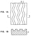
- Figs.1A and 1B illustrate a schematic view of such a disc. Wobbled grooves 11 are spaced apart in the surface of substrate and are separated from each other by inter-groove (land) spaces 2. It is to be noted that the amplitude of the wobble is shown exaggerated. The wobble is formed by a frequency modulation using a carrier frequency of 22.05 kHz.
- the wobble amplitude is very small in comparison to the pitch of the groove 11, which is a distance measured between imaginary centerlines of grooves 11 located on the opposite side of the inter-groove space 12 and is normally on the order of 1.6 ⁇ m, and is on the order of 30 nm.
- a frequency modulation of the wobble in accordance with absolute time information or address information is referred to as ATIP (Absolute Time In Pre-groove) or ADIP (Address In Pre-Groove), and is already utilized in a recordable compact disc (CD-Recordable or CD-R) and mini-disc.
- CD-Recordable or CD-R recordable compact disc
- mini-disc See "CD Family” by Heitaro Nakajima, Takao Ihashi and Hiroshi Ogawa, Published from OHM-sha in 1996, Chapter 4, and Proceedings of the IEEE, Vol. 82(1994). Page 1490.
- Such a file management area is a small limited region which is disposed along the innermost or outermost periphery of the entire recordable region of the optical disc, and remains to be less than several percents of the entire recordable region; a degradation attributable to the wobbled groove presents a problem mainly in the TOC region as far as the CD format is concerned. However, this represents a very important region in which the content of the user data is recorded. Once an error occurs in this region, there results a failure to read data from the entire data area, and the disc can no longer be used, thereby limiting the life of the disc.
- a reserve track may be secured for use as a substitute for the file management area so that the substitute track may be used when an increased number of errors occur as a result of overwriting operations.
- a procedure of the file management is troublesome, presenting a difficulty in the design for drives and device drivers.
- the actual circumstance is that the number of overwriting operations which can be repeated for the entire disc is limited due to the presence of a region which is frequently overwritten and which occupies less than several percents.
- the signal deformation of the groove geometry as used in this text is referred to as deformation or modulation of the groove that is applied to the wobble configuration or width or depth of the groove in accordance with address data, synchronization data or other specific data.
- the modulation is implemented by vibrating the exposure beam on a glass master in manufacturing process of a stamper in the direction normal to the direction of the groove during the exposure of the glass master, and subsequent transcription of the vibration onto the substrate by injection molding.
- the typical deformation of the groove is implemented by the wobble of the groove.
- the constant groove as used herein means that the groove is not applied with the wobble configuration or modulation and extends in a constant configuration.
- the present invention achieves advantages of suppression of degradation in a phase-change disc caused by repeated overwriting operations to improve reliability and durability of the phase-change disc.
- the invention uses a technique to record a frequency-modulated signal in accordance with a rotational synchronization pattern or address information in the form of a groove wobble, as disclosed, for example, in JP-A-2(1990)-87344.
- the groove wobble can be formed by oscillating an exposure beam for groove formation in the direction normal to the groove during fabrication of a prototype glass master in mastering process.
- a large number of replicas can be manufactured by transferring the shape of the glass master onto resin substrates by using an injection molding technique (see, for example, JP-A-1(1988)-103454, -2(1990)-87344, -2(1990)-198040 and 3(1991)-88124, and -3(1991)-287657, JP-8-3(1991)-23859 and -3(1991)-3168).
- ATIP or ADIP signal recorded or described by the wobble is used in the control of the rotational speed in the unrecorded region and addressing in the data area.
- the present inventors have found that a degradation resulting from a repeated overwriting operations is promoted in a CD-RW (rewritable compact disc) of phase-change type by the presence of the wobble, and noted that the degradation causes a more serious problem in the future when a higher track density is used.
- the inventors have also found that a promoted degradation can be suppressed under a specific condition.
- a substrate may comprise a transparent resin such as polycarbonate, acrylic resin or polyolefin, or glass.
- a recording layer of phase-change type has its both sides coated with protective layers. It is desirable that the disc has a layer structure as shown in Fig. 2 including lower protective layer 14 of a dielectric material, recording layer 15, upper protective layer 16 of a dielectric material and reflective layer 17 consecutively formed on a substrate 13.
- the top of the disc may be preferably coated with a protective overcoat 18 comprising ultra-violet ray curable or themosetting resin.
- the reflective layer 17 is provided in order to take advantage of an optical interference effect positively to thereby increase the signal amplitude and to provide a function as a heat dissipating layer to thereby assist in achieving a super-cooled condition required to form an amorphous mark.
- a metal having high reflectivity and high thermal conductivity such as Au, Ag and Al
- a semiconductor such as Si, Ge or the like may be used in order to make a design choice in some instance.
- the addition of Ta provides a high corrosion resistance (JP-A-1(1989)-169751).
- the protective layer 14 disposed on the surface of the substrate has a thickness in a range from 10 to 500 nm.
- the choice of a material for the protective layers 14 and 18 is determined in consideration of refractive index, thermal conductivity, chemical stability, mechanical strength, adherence to other layers and the like.
- the oxides sulfides and nitrides of metals or semiconductors and fluorides of Ca, Mg, Li or the like, which are highly transparent and has a high melting point can be used. It is unnecessary that these oxides, sulfides, nitrides and fluorides have a stoichiometric composition, but the composition may be controlled or a mixture may be used in order to control the refractive index or the like.
- a dielectric mixture is preferable when the repeated recording response is considered. More specifically, a mixture of ZnS or rare earth sulfide and a refractory compound such as oxides, nitrides or carbides is preferable. It is desirable from the standpoint of the mechanical strength that the film density of such a protective layer be equal to or greater than 80% of the bulk (see “Thin Solid Films", Vol. 278 (1996), pp.74.81).
- the dielectric layer having a thickness below 10 nm may be insufficient to prevent a deformation of the substrate or recording layer as a protective layer. If the thickness is above 500 nm, internal stresses within the dielectric layer itself and the differential elastic response with respect to the substrate become remarkable, tending to produce cracks. In particular, it is preferable to suppress a deformation of the substrate due to heat by the lower protective layer, and a thickness equal to or greater than 70 nm is preferable for this purpose. Below a thickness of 70 nm, a microscopic deformation of the substrate is accumulated during the repeated overwriting operations, whereby a reproduced light is scattered causing a considerable increase of noise.
- An upper limit on the thickness of the lower protective layer is substantially on the order of 200 nm in consideration of the deposition time. If the thickness of the lower protective layer is larger than 200 nm, the configuration of the groove as viewed in the plane of the recording layer will be changed, which is undesirable. Specifically, the depth of the groove may become shallower than intended on the surface of the substrate, and the groove width may also be narrower than intended on the surface of the substrate, both of which are undesirable.
- a preferred upper limit on the thickness of the lower protective layer is 150 nm or less.
- a thickness of at least 10 nm or more is required for the upper protective layer 16 in order to suppress the deformation of the recording layer. If the thickness is greater than 60 nm, there is a tendency that a microscopic plastic deformation is accumulated within the upper protective layer during the repeated overwriting operations, and this causes a reproduced light to be scattered, thereby increasing undesirable noise.
- the recording layer in the disc of the invention is of phase-change type, and has a thickness which is preferably in a range from 10 nm to 100 nm. If the thickness of the recording layer is less than 10 nm, a sufficient contrast cannot be obtained, and there is also a tendency to retard the recrystallization rate, presenting a difficulty in erasing a record in a short time interval. On the other hand, if the thickness exceeds 100 nm, an optical contrast is difficult to achieve, and a crack is likely to be produced, which is again undesirable. For practical purposes, a thickness equal to or greater than 10 nm and below 30 nm is used in order to assure a high contrast which provides a compatibility with CD. Below 10 nm, the reflectivity is too low, whereas above 80 nm, a heat capacity increases to degrade a recording sensitivity.
- a recording layer may be an optical recording layer of phase-change type which is known in the art, and may comprises a compound such as GeSbTe, InSbTe, AgSbTe or AgInSbTe, for example, is selected as an over writable material.
- a thin film comprising as a main constituent the following alloy: ⁇ ( S b 2 T e 3 ) 1 ⁇ x ( G e T e ) x ⁇ 1 ⁇ y S b y ( 0.2 ⁇ x ⁇ 0.9 , 0 ⁇ y ⁇ 0.1 ) or M w ( S b z T e 1 ⁇ z ) 1 ⁇ w ( 0 ⁇ w ⁇ 0.3 , 0.5 ⁇ z ⁇ 0.9 ) , and where M represents at least one selected from the group comprising In, Ga, Zn, Ge, Sn, Si, Cu, Au, Ag, Pd, Pt, Pb, Cr, Co, O, S, Se, V, Nb and Ta is stable in either crystallized or amorphous state, and allows a rapid phase transition between the both phases.
- Such a material is a most practical in view of the advantage that it is less susceptible to segregation after repeated overwriting operations.
- the recording layer is
- the thicknesses for the recording layer and protective layers 15 are selected for a desirable absorption efficiency of laser irradiation and an increased amplitude of recorded signal, i.e., a better contrast between an recorded and an unrecorded states, in consideration of an interference effect caused by a layer structure in addition to the restrictions imposed by the mechanical strength and the reliability.
- the recording layer 15, the protective layers 14 and 16 and the reflective layer 17 are formed by a sputtering technique.
- a thin film deposition process is conducted in an in-line equipment including a vacuum chamber in which a target for the record film, a target for the protective films, and if desired, a target for the reflective layer are disposed in common. This is advantageous from the standpoint of productivity.
- phase-change disc microscopic deformation is accumulated in the protective layers or the surface of the substrate due to repeated overwriting operations, thereby scatters the focused optical beam to increase noise in the reproduced light or to change the thickness of the recording layer and protective layers, which retard accurate detection of the mark length.
- the degree of degradation due to the repeated overwriting operations depends on the geometry of the groove.
- the present inventors found that the progress of the degradation due to the repeated overwriting operations is low in a constant groove having a larger depth and a smaller width in case of recording in the groove, and that the configuration of the groove is determined thereby.
- the reason therefor is considered to result from a confinement effect of the recording layer. That is, it is believed that the deeper and narrower the groove, the more the melted region is limited in the groove during recording operation to suppress the width of the deformed region in the bottom of the groove during the meltdown of the recording layer.
- the distortion of the groove geometry due to the overwriting operation applies to the groove wall.
- the groove wall suffers from thermal damage due to the poor adherence to the thin film and stress concentration at the corner during the repeated overwriting operation. Accordingly, even if only a part of optical beam is irradiated onto the groove wall, degradation will be promoted.
- a distortion in the groove geometry which results from the repeated overwriting operations occurs more or less because the softening point of the resin is far below the temperature of the phase-change disc during the phase-change operation, the temperature being several hundred degrees centigrade or higher.
- the overwriting durability of the groove limits the range of the groove width which is determined relative relationship between the groove width GW and the diameter R 0 of the focused optical beam as viewed in the direction normal to the groove.
- the energy distribution of the recording focused optical beam is determined by a Gaussian distribution, and the degree of the degradation is determined by the portion of the Gaussian distribution actually applied to the groove wall.
- the diameter R 0 of the focused beam in the direction normal to the groove as used herein is referred to as the diameter at which the intensity of Gaussian beam is 1/e 2 .
- the critical light intensity irradiated to the groove wall is approximately 40% of the light intensity at the center of the groove, and the groove wall should be located outside the critical location.
- temperature distribution in the recording layer is investigated.
- the calculation for the temperature distribution resulted in up to the temperature of 1000°C at the beam center during irirradiation for forming an amorphous mark.
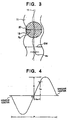
- the presence of the wobble tends to cause the focused light beam 19 which is used for the recording operation, to irradiate partly a sidewall 20 of the groove, as illustrated in Fig. 3.
- the beam 19 to which tracking servo feedback is applied does not accurately follow the wobble, rather passes straightforward along the centerline 21 of the groove 11. Accordingly, the light beam 19 tends to irradiate the groove wall 20 even though slightly.
- the wobble amplitude a w is shown exaggerated in Fig. 3 but it is believed that the tendency illustrated is correct.
- the wobble amplitude is on the order of 1 to 10 nm, and accordingly, the distortion of the groove in the order of 2 to 3 nm considerably degrades the wobble signal quality.
- C/N (carrier to noise) ratio degrades, but also S/N (signal to noise) ratio for the signal recorded in the groove degrades.
- S/N signal to noise
- the groove width should be narrow enough so that GW/R 0 ⁇ 0.45, or wide enough to neglect the degradation of the groove wall so that 0.65 ⁇ GW/R 0 in order to reduce the degradation due to the repeated overwriting operations.
- the groove width GW should satisfy the following relationship: 0.25 ⁇ G W / R 0 ⁇ 0.45 , or 0.65 ⁇ G W / R 0 .
- the degradation caused by the wobble depends also on the wobble amplitude a w .
- the configuration a w /GW ⁇ 0.08 is essential to prevent the degradation of envelope due to the wobble distortion.
- an extremely smaller wobble amplitude does not provide a sufficient signal intensity for the wobble signal.
- the wobble amplitude has a lower limit because C/N of the wobble signal should be equal to or above 25 dB and an upper limit because the degradation caused by repeated overwriting operations, as follows: 0.03 ⁇ a w / G W ⁇ 0.08 The value is determined experimentally. This relationship depends not on the wavelength of optical beam or NA, but on beam diameter R 0 in the direction normal to the direction of the groove and relative relationship between wobble amplitude a w .
- the wobble amplitude is defined by a measurement as described below:
- the wobble amplitude of the groove i.e., the displacement from the mean center of the groove can be determined from this equation.
- Fig. 4 shows a servo error signal.
- CD-RW CD-RW
- the invention is not limited to the current CD, but is also applicable to a recording a disc having a higher density which is constructed similarly to the current CD where a rotational synchronization signal can be generated and an address signal may be produced by utilizing the groove wobble.
- a phase-change disc exhibits a more excellent durability against overwriting operations in an ingroove recording than in an inter-groove (or on-land) recording. While the reason therefor is not clearly understood, it is believed to be a result of an effective protection of an edge area of a recording layer by the groove wall. Such a protective effect (groove confinement effect) is not satisfactory for a groove depth below 26 nm.
- a second aspect of the invention is directed to a method of substantially improving the durability in the file management area which is more frequently overwritten than other area.
- ATIP signal or ADIP signal which is described by the wobble or TOC will be described more in detail.
- the ATIP signal described by the wobble is used in controlling the rotational speed of a non-recorded area and in addressing of data area. (refer to Compact Disc Dokuhon" by Heitaro Nakajima and Hiroshi Ogawa, published by OHM-sha, third revised edition 1996, "CD Family” cited above and above cited Japanese Patent Publications)
- FIG. 6 is a schematic view showing a radial layout of recording area in CD and rewritable CD.
- a disc region on CD and recordable CD includes a clamping area (a1) which is located along the innermost periphery, which is followed toward the outer periphery by PCA (Power Control Area) or PMA (Program Memory Area) (a2), a lead-in area (a3), a program area (a4) which corresponds to the data area as termed in the present invention, and lead-out area (a5).
- a physical location on a track corresponds to absolute time information of ATIP.
- a user file is recorded in the program area a5 beginning from an origin in time axis which is an innermost track toward the outer periphery.
- TOC which describes its address in terms of the absolute time on the ATIP is entered in the lead-in area a3 which immediately precedes it.
- the beginning position (time) of the lead-in area is ususally the beginning position (time) of the TOC.
- a unit of such data is referred to as one frame of ATIP, one block of EFM data or one subcode frame. Since the absolute time and rotational synchronization signal of every frame is independent from a data scrambling operation which is performed for the purpose of error correction, they are disposed so that the absolute time proceeds from the inner to the outer periphery.
- a control over the rotational speed in the unrecorded region takes place by reading a synchronization pattern located at the leading end of one frame of ATIP signal.
- the absolute time or address information and synchronization information can be detected from a synchronization pattern of every EFM frame in the similar manner as in ROM (Read Only Memory) disc.
- an synchronization signal from this track may be used to control the rotational speed of the disc.
- the rotational speed reaches a steady-state there occurs no disturbance which presents a problem to synchronization between the clock signal and the rotational speed even if a feedback of synchronization pattern of ATIP signal is unavailable from the TOC area.
- An exact synchronization is detected again at a position where an access is made to the program area with reference to the TOC.
- Fig. 7 is an illustration of an exemplified CD.RW to which the invention is applied.
- Formed on the spiral groove are a preliminary area 22, a file management area (lead-in area) 23 and a data area beginning from the inner periphery of the disc. Except for the file management area 23, ATIP is recorded in terms of the groove wobble.
- the preliminary area 22 is used for the purpose of lead-in of a focused light beam adjustment of the recording power and/or achieving rotation synchronization.
- an addressing and a control over the rotational speed can be made even without ATIP once the EFM modulated data is recorded.
- some record can be previously made in the file management area in terms of EFM modulation signal, or alternatively, some means is used to detect the heading and to make a record only during the initial access to the file management area as a formatting process on the conventional hard disc drive, and subsequently the recorded signal may be utilized.
- special information region which records heading location information of the file management area as a groove wobble may be given at a given location in the disc.
- the drive initially accesses the special information region to detect the heading information of the file management area. It is desirable that the special information region be located at a position which is initially accessed by the drive, for example, in the preliminary area 12 as shown in Fig. 7.
- the special information region may be preferably located around the outer periphery.
- information for the optimum recording power of the disc or information for the drive control may be recorded in superimposition in the ATIP signal of the file management area. In this instance, if a degradation due to the repeated overwriting operations occur, such information can no longer be retrieved correctly.
- control information can be recorded in the specific information region as EFM signal. The recorded information may be once read by the drive, and then recorded in the file management area in the form of the EFM signal contained in the file management information.
- EFM modulation signal including the absolute time information or the address information may be recorded in the file management area as an initialization or post-formatting procedure upon shipment of disc from the factory.
- a special drive is prepared on the part of a disc manufacture, and, for example, the leading address of the data area may be entered as the leading address of the unrecorded region.
- other information which are used for the drive control may be recorded in EFM signal as well. This is preferred because there is no need for a special function in the drive on the user side.
- the dummy data in the file management area may be recorded in any sequence. For example, when the file management information is recorded beginning from the leading end of the file management area, it is preferred to record the dummy data including the synchronization information and address information from the end of file management information to the end of file management area.
- the end of the file management information may be arranged to coincide with the end of the file management area.
- only the dummy data may be recorded over the entire unwobbled file management region.
- an optical information recording method which uses the disc described above and in which the beginning position of recording is displaced each time a part or all of the file management information inclusive of dummy information is re-written. It is known that when repeated overwriting operations take place, it is useful to displace the beginning position of recording in an incremental manner for the purpose of retarding a degradation in the signal which results from a transfer of the material in the phase-change disc (see JP-A-2(1990)-94113 and -3(1991)-150725).
- a degradation in a signal can be reduced.
- the amount of displacement is limited to a certain degree since it may exceed the permissible range of the absolute time information. A sufficient improvement can be obtained with a displacement on the order of 10 to 100 ⁇ m, for example.
- the data signal is not limited to the EFM modulation signal, but may comprise any modulation signal including address information and synchronization information.
- Providing a deformation in the signal of the groove geometry is one way of achieving a higher density in a recording disc, and is also applicable to a recording disc having a different format.
- the invention is also effective in such an instance.
- ISO9660 standard is known as the logical format standard which also covers CD standards. According to the current CD standards, only the physical file structure is described for the file management area, and a physical position in unit of data block is described as absolute time information.
- a hierarchical structure or so-called directory structure is not described.
- a physical structure is described in the file management area, and a directory structure is described in a specified region of the data area as a path table.
- the path table in this specified region can also be contained in the file management area as termed in the invention.
- JP-A-5(1993)-210849 describes a temporary or transitory recording of file management information in a specified region other than the final file management area.
- the lead-in area a3 shown in Fig. 6 is not rewritten every time, but the file management information stored temporarily in such a temporary area a2 is rewritten (see JP-A-5(1993)-210849), it is desirable to treat this region as the file management area to which the invention is applied.
- the need to secure and control a replacement region, as by re-recording the file management information in a replacement region which is not degraded, may be eliminated, thereby greatly facilitating a file control procedure and also facilitating a design of the drive and device drivers.
- a method of rewriting information in sector by sector as occurs in a magneto-optical disc has not been established for CD-RW.
- CD-RW it is expected that a number of times a particular sector is rewritten will amount to one hundred thousand to million times or greater.
- the present invention achieves a remarkable effect on suppressing a degradation, which results from the repeated overwriting operations, by simple means and at a reduced cost.
- the groove width and the wobble amplitude should be determined by the following equations: 0.25 ⁇ G W / R 0 ⁇ 0.45 or 0.65 ⁇ G w / R 0 0.03 ⁇ a w / G w ⁇ 0.08 thereby enhancing the overall reliability for durability against the repeated overwriting operations.
- a third aspect of the invention relates to a method of incrementally writing data at random in block unit generally referred to as "packet writing".
- Incremental recording in write-once mode is already in practical use with CD.R, where a data capacity which is recorded at one time is varying. Since in this application user data is continuously recorded from the inner to the outer periphery, unrecorded region is located radially outward of a recorded region. There can be no recorded region which is located radially outside the unrecorded region. Accordingly, it is a simple matter to detect a synchronization and an absolute time from the EFM signal in the recorded region and to detect a synchronization pattern and an absolute time from the ATIP signal in the unrecorded region.
- the ability is required to record user data in unit of given packet (sector) such as 2 n bytes, for example, as occurring in a hard disc (HD), floppy disc (FD) or a magneto-optical disc (MO).
- a data control to deal with such a sector unit of fixed length is required in CD-RW in order to take advantage of its rewritability, since unless overwriting data is physically constrained within a given length, the overwriting may extend to data which are not to be erased.
- a demarcation between sectors, sector addresses and synchronization signal are previously pre-formatted in terms of pit trains in the substrate in MO.drive or post-formatted in terms of recorded signal in HD or FD drives.
- Fig. 8 shows an example of sector arrangement for MO.
- a pit train which constitutes a header 25 and a user data area 26 are alternately disposed in the circumferential direction, and one set of the header 25 and the data area 26 constitutes a sector 27. It is to be noted that the length of the header 25 is shown exaggerated in Fig. 8.
- CD-DASD Compact Disc Direct Access Storage Disc
- ATIP signal is formed as a wobble between the ends of a track without interruption.
- address signal contained in ATIP signal, ADIP signal or EFM signal.
- Fig. 9 is a schematic plan view of CD-RW disc according to one embodiment of the invention.
- a guide groove 11 used as a data track and a land 12 are alternately disposed in the radially direction, and additional data area 28 and user data area 29 are alternately disposed in the circumferential direction of each data track 11.
- a guide groove section 31 having a wobble which is modulated according to a given signal is formed in the additional data area 28 whereas a guide groove section 32 which is not formed with a wobble is formed in the user data area 29.
- a pseudo-sector (or packet) 30 comprising a set of preceding additional data area 28' + user data area 29 + following additional data area 28" is laid for each length of absolute time T which is described by the ATIP signal in the guide groove of the disc. Either one of the additional data areas 28' or 28" may be used.
- the user data area 19 is in unit of 2 n bytes, for example.
- the set of data is referred to as packet
- the physical structure on the disc on which the packet is recorded is referred to as pseudo-sector
- the additional data area is referred to as a pseudo-header, utilizing the concepts and the terminology used with HD or MO.
- the drive may give rise to a delicate error in the position of the beginning or the end of the packet writing in view of the rising time of a laser or rotational jitter in drive system when a recording operation actually takes place by the modulation of the laser irradiation.
- the length of an pseudo physical sector along the track is equal to a constant value of VT, apart from the gap, and the additional data area 28 is disposed every given interval VT along the track. Since the length of each pseudo-sector is constant, it is possible to allocate the absolute time to the position of leading end of each sector by calculation, or it is possible to describe it in the lead-in area.
- ADIP signal which does not depend on the absolute time.
- address information for the leading end of each sector is read from ADIP signal rather than pre-pits, as occurring in MO disc according to ISO standard.
- the invention relates to a so-called packet writing technique which utilizes the pseudo-sector, does not directly relate to a detailed technique of various proposals, and has for its object an improvement of the durability against the repeated overwriting operations in a overwritable phase-change disc in which a fixed length of data (packet) can be repeatedly recorded on the same pseudo sector.
- the wobble is formed only in the pseudo-header region 28, and not formed in the user data area 29, as shown in Fig. 9.
- At least user data area 29 has a groove formed with the wobble satisfying the following relationship: 0.25 ⁇ G W / R 0 ⁇ 0.45 or 0.65 ⁇ G W / R 0 0.03 ⁇ a w / G W ⁇ 0.08.
- the choice of either configurations depends on a choice in the design to place greater significance upon either the durability against overwriting operations or the improved accuracy in the synchronization of rotation which is brought forth by the presence of the wobble. If the former is selected, an excellent durability against overwriting operations can be obtained when accuracy in the synchronization of rotation is additionally improved by another method without retarding the durability against the overwriting operations. If the latter is selected, an excellent accuracy in the synchronization of rotation can be obtained, although the durability against overwriting operations is somewhat reduced without any practical problem.
- added data such as address information can be recorded in the groove or inter-groove in the additional data region or pseudo-header section as a pre-pit train.
- an initialization (post-formatting) operation may record the address information in the same recording format as the user data in the additional data area.
- the formation of the groove is made possible by opening a gate G1 between a modulation signal generator CM1 which produces a modulation signal used in forming a wobble, and a laser oscillation drive unit EO which emits an exposure laser beam for irradiating a prototype glass plate 23.
- An arrangement is made to produce absolute time information from a modulation signal M1 uninterruptedly, as in the prior art, while a sector header switching unit CM2 is made to produce a gate signal M2 which causes gate G1 to be opened at the position of the pseudo-header. In this manner, a wobble modulation signal M1 is intermittently supplied to the EO drive unit.
- the absolute time in the wobble modulation signal M1 is allowed to proceed in CM1 so that the absolute time of each pseudo-sector is an exact function of the position when the disc is rotated according to the CLV scheme even though the description of the absolute time is given at intervals.
- the groove width is reduced by 10 to 50% than in the pseudo-header region so as to satisfy the first relationship in inequality (1), thereby improving the durability against the repeated overwriting operations as the whole disc.
- a control over the groove width can be accomplished readily by controlling the power of exposure laser beam during the exposure of photoresist placed on the prototype glass plate.
- the oscillation of the wobble is turned on and off, and the intensity of the laser beam is switched between two levels.
- address information which is described in terms of synchronization and absolute time is read from ATIP signal in the pseudo-header region, thus initially establishing a given synchronization of rotation. Subsequently, an address is indexed, followed by a recording operation of the EFM signal over the entire pseudo-sector which begins at the desired absolute time.
- synchronization and absolute time may be recorded in the wobbled pseudo-header region in terms of the EFM signal, and subsequently, an access to a desired sector can be made with reference to data represented by the EFM signal without reference to ATIP signal.
- the access to each pseudo-sector can be made by retrieving the recorded EFM signal rather than ATIP signal on the wobble.
- the EFM data in the wobbled pseudo-header region be rewritten for each packet writing. If the added data is recorded in terms of EFM signal in the pseudo-sector, only the user data is overwritten during a second and a subsequent recording operations.
- the present invention can be introduced into accommodation on the part of the future ROM drive.
- the file management area is also referred to as a disc control area.
- a series of file management information area is usually disposed collectively at a specified location along the inner or outer periphery of the actual disc.
- the second and third aspects of the invention may be combined, thereby substantially completely eliminating the periodic deformation of the groove in the file management area.
- the first and the third aspects of the invention may be combined to provide the wobbled groove in the file management area which satisfies the relationships (1) and (2) given above.
- a degradation of a recording response is little noticeable after 10,000 overwriting operations, even though a degradation is noted after 1000 repetitions of overwriting operations in the prior art. In some instances, a degradation in the response was noticed after repetitions on the order of 100,000 times. Accordingly, the need, experienced in the prior art, to secure and control a replacement area in order to allow a rewriting of the degraded pseudo-sector can be eliminated or reduced, the pseudo-sector being undergone degradation as a result of repeated overwriting operations which happened to occur in this sector in a concentrated manner. Accordingly, a file control procedure is simplified, also simplifying a design of the drive and the device drivers.
- a technique of writing/rewriting in sector unit as occurring in a magneto-optical disc is not yet established with CD-RW disc.
- the number of rewritings is expected to become enormous (for example, up to one hundred thousand to million times or more). It is expected that in such instance, the invention allows a degradation occurring as a result of repeated overwriting operations to be suppressed readily and inexpensively.
- a rewritable phase-change disc will be described below, in which a groove having a configuration modulated in accordance with rotational synchronization signal is formed and a record is made in both within the groove and the inter-groove space or land.
- a method which records information in both the land and the groove will be abbreviated to hereafter as L&G (Land and Groove) recording.
- L&G recording is proposed in JP-B-63(1988)-67859.
- a spacing between a train of recording marks on a track and a train of recording marks on an adjacent track will be equal to one-half diameter of the focused beam, whereby the train of recording marks on the adjacent track adjacent to the track to be retrieved will be irradiated by the focused beam. This increases the crose-talli during the retrieval, degrading S/N ratio in the retrieved signal.
- a technique is proposed to reduce the cross-talk by providing a special optical system and a cross-talk canceling circuit in an optical disc playback unit, for example (SPIE Vol.1316, Optical Data Storage (1990), p. 35).
- SPIE Vol.1316, Optical Data Storage (1990), p. 35 SPIE Vol.1316, Optical Data Storage (1990), p. 35).
- the proposed technique complicates the optical system and the signal processing system of the playback unit.
- a phase difference a (the phase of a reflected light from a unrecorded region ) ⁇ (the phase of a reflected light from a recorded region ) satisfies the following relationship, as described in JP-A-7(1995)-287872: ( m ⁇ 0.1 ) ⁇ ⁇ ⁇ ⁇ ( m + 0.1 ) ⁇ where m is an integer.
- the durability of the land against repeated overwriting operations depends on the relative relationship between the land width and the beam diameter, and when the land width becomes narrower than a specified value with respect to the beam diameter, a degradation proceeds rapidly. Specifically, if the land width lies in a range form 0.62 ⁇ ( ⁇ /NA) to 0.8 ⁇ ( ⁇ /NA), there occurs no failure in erasing previously recorded marks during repeated overwriting and no substantial degradation of the jitter of the recorded marks, maintaining an equivalent response as occurring during recording in the groove. However, when the land width is below the range described above, a failure in erasing the previous marks is remarkable during the repeated overwriting operation in the land, the jitter of recorded marks is degraded significantly.
- Cross-erase phenomenon depends on a relative relationship between the beam diameter and the pitch of the recording track.
- the groove pitch (GW+LW) of the L&G recording is selected to be greater than 1.2 ⁇ ( ⁇ /NA) or when the substantial track pitch ⁇ (GE+LW)/2 ⁇ is greater than 0.6 ⁇ ( ⁇ /NA), a degradation in the signal from an adjacent track which is caused by the cross-erase can be suppressed, and a reduction in the CN ratio after 10,000 times of overwriting operations can be suppressed below 3 dB, which is a level presenting substantially no problem for practical purposes, The theoretical background therefor will be considered below.
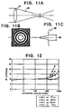
- Figs. 11A, 11B and 11C are a schematic views of a configuration of a focused beam, Fig. 11A showing cross-sectional view of the beam, Fig. 11B showing the intensity distribution in a plane, Fig. 11C graphically showing the level of the intensity distribution in Fig. 11B.
- a focused beam 34 which passed through a focusing lens 87 has an intensity distribution 35 which includes a main peak and sub-peakf;.
- a center spot which is represented by the main peak has a diameter which can be substantially represented as 1.2 ⁇ ( ⁇ /NA), which is referred to as an airy disc 36.
- the figure of 0.6 ⁇ ( ⁇ /NA) correspond to just half the airy disc theoretically.
- a recording layer of phase-change type which is currently known and principally comprises 40 atomic % or more of GeSbTe, AgInSbTe, InSnTe, InSbTe or other III b, IV b, V b or VI b group element either alone or in mixture (namely, as an alloy) has a thermal conductivity which is by two or three orders of magnitude below that of a magneto-optical recording layer.
- the recording layer is substantially adiabatic in the lateral direction. Accordingly, cross-erasing phenomenon is little influenced by the thermal conduction of the recording layer.
- the minimum track pitch is substantially determined by the beam diameter, and hence by the wavelength of the light beam and NA alone.
- a modification of multilayer structure of the recording disc and a restriction of the physical properties of the recording layer appear to be effective, though slightly, to reducing the cross-erase after 10,000 times of repeated overwriting operations.
- the thickness of recording layer exceeds 30 nm, the recording sensitivity is degraded, causing the cross-erase to increases because of heat transfer to adjacent tracks during the recording operation.
- the groove width GW and the inter.groove space width LW are also limited by restrictions imposed in connection with a cross-talk, the cross-erase and the durability against the overwriting operations in the inter-groove space recording.
- the groove width GW, the width LW of the inter-groove space (i.e., land width) and the groove depth d satisfy the following relationships: 0.3 ⁇ m ⁇ G W ⁇ 0.8 ⁇ m 0.3 ⁇ m ⁇ L W ⁇ 0.8 ⁇ m 0.62 ⁇ ( ⁇ / N A ) ⁇ L W ⁇ 0.8 ⁇ ( ⁇ / N A ) ( G W + L W ) / 2 > 0.6 ⁇ ( ⁇ / N A ) ⁇ / 7 n ⁇ d ⁇ ⁇ / 5 n
- ⁇ , n and NA represent the wavelength of a focused light beam, the refractive index of a substrate and the numerical aperture of the focusing lens, respectively.
- one or all of the first to the third aspects of the invention may be applied, thus providing a disc of a high density and a high reliability which has an improved cross-talk and cross-erase resistance and improved durability against repeated overwriting operations.
- a quadri-layer structure including a lower protective layer of ZnS:SiO 2 (200 nm), a recording layer of Ag 5 In 6 Sb 60 Te 29 alloy (20 nm), an upper protective layer of ZnS:SiO 2 (20 nm) and a reflective layer of Al 98.5 Ta 1.5 alloy (200 nm) was formed by a sputtering process.
- a protective overcoat comprising ultra-violet ray cured resin was provided on top of the quadri-layer structure.
- Wobble was formed as an unmodulated signal of 22.05 kHz, and was transferred onto a polycarbonate substrate having a diameter of 120 nm and a thickness of 1.2 nm by injection molding technique.
- the groove had a pitch of 1.6 ⁇ m, a width of about 0.5 ⁇ m and a depth of about 40 nm.
- An amorphous mark was formed within the groove.
- the recording was made by using an optical disc drive DDU 1000 manufactured by PULSTEC Company and carrying an optical head having an NA of 0.55 and emitting a light beam of wavelength 780 nm and having a beam diameter of 1.35 ⁇ m.
- the recording was effected by using a divided pulse technique as illustrated in Figs.
- 3T mark jitter was from 9 to 11 nsec.
- the number of times (the number of overwriting operations) until the 3T mark jitter reaches 17.5 nsec was determined.
- the CD-RW standard requires a durability in excess of 1,000 times, and in the present Embodiment, a disc which demonstrated a number of times equal to or greater than 1,000 times was regarded as acceptable.
- the wobble amplitude was determined according to the technique described in the orange book.
- the groove width was determined by the optical diffraction method (U-groove approximation).
- Table 1 indicates the number of repeatable times for various values of W/R 0 and a w /W thus obtained. In this table, an area surrounded by a bold line represents results of this Embodiment, and the remainder relates to the Comparative Example.
- a quadri-layer structure including a lower protective layer of ZnS:SiO 2 (150 nm), a recording layer of Ge 23 Sb 25 Te 52 alloy (20 nm), an upper protective layer of ZnS:SiO 2 (20 nm) and a reflective layer of Al 98.5 Ta 1.5 alloy (100 nm) was produced by a sputtering process.
- a protective coat of ultra-violet ray cured resin was provided on the quadri-layer structure.
- the beam had a wavelength of 780 nm.
- the wobble had a C/N ratio which was equal to or greater than 25 dB.
- a recording disc having the same layer structure as described above in connection with the Embodiment 1 was formed except for the groove width of 0.53 ⁇ m, the groove depth of 20 nm and the wobble amplitude of 27 nm.
- the number of repeatable times was on the order of 500. It is considered that this is attributable to a shallow groove depth.
- a substrate was prepared in a similar manner as described above in connection with the Embodiment 1 except for the groove width of 0.53 ⁇ m, the groove depth of 30 nm and the wobble amplitude of 27 nm.
- the similar layer structure was prepared as above except for the lower protective layer having a thickness of 60 nm.
- a substrate was prepared in a similar manner as described above in connection with the Embodiment 1 except for the groove width, groove depth and wobble amplitude of 0.53 ⁇ m, 35 nm and 27 nm, respectively.
- the similar layer structure was used as above except that for the upper protective layer having a thickness of 65 nm.
- a spiral groove Formed in a polycarbonate substrate which was injection molded to a diameter of 120 nm and a thickness of 1.2 mm was a spiral groove having a pitch of 1.6 ⁇ m, a width of about 0.5 ⁇ m and a depth of about 40 nm.
- a wobble with a signal of 22.05 kHz was formed in the groove.
- the wobble was formed in four types having amplitudes of 27 nm, 20 nm, 13.5 nm and 0 nm (no-wobble).
- Sequentially laminated on the substrate were a lower protective layer of (ZnS) 80 (SiO 2 ) 20 (mol%) to a thickness of 100 nm, a recording layer of Ag 5 In 6 Sb 61 Te 28 to a thickness of 20 nm, an upper protective layer of (ZnS) 80 (Sio) 20 to a thickness of 20 nm and finally a reflective layer of Al 97.5 Ta 2.5 to a thickness of 100 nm.
- Ultra-violet cured resin SD318 manufactured by Dainippon Ink.
- a recording was made within the groove, forming amorphous marks in the crystallized region.
- the disc was repeatedly overwritten in an accordance with EFM random signal using a velocity (2.8 m/s) which was double the velocity used with CD.
- the recording operation was performed by using an optical disc drive DDU1000 manufactured by PULSTEC Company and carrying an optical head having an NA of 0.55 and emitting a light beam of wavelength 780 nm and having a beam diameter R 0 of 1.35 ⁇ m.
- An overwriting operation is effected by using a divided pulse technique as indicated by a laser irradiation pattern shown in Figs. 5A and B with a recording power Pw of 11 mW, an erasing power Pe of 6 mW and a bias power Pb of 0.8 mW.
- the signal quality was evaluated in terms of 3T jitter which was most stringent. It is required by the CD standard that the jitter be on the other of 17.5 nsec or less at the double velocity.
- Fig. 12 graphically shows results of measurement of 3T jitter for wobble amplitudes of 27 nm, 20 nm, 13.5 nm and 0 nm or no-wobble. It will be apparent from this Figure that for a groove which has no wobble, there is little degradation of jitter after 10,000 times of overwriting operations, but the degradation increases markedly with an increase in the wobble amplitude, and becomes remarkable at a point which corresponds to the order of 1,000 times. It is also to be noted that the degree of degradation caused by the repeated overwriting operations also depends on the cross-sectional geometry of the groove.
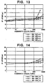
- Fig. 13 graphically illustrates a degradation of the recording response caused by wobbled groove which is arrayed at pitch of 1.6 ⁇ m.
- the groove depth remains constant, but the groove width alone is changed between 0.40 ⁇ m, 0.56 ⁇ m, 0.68 nm and 0.80 ⁇ m.
- a groove width W as measured at half the groove depth H/2 is taken as the effective groove width, as indicated in Fig. 15.
- a polycarbonate substrate having a spiral groove was prepared by injection molding.
- the refractive index at a wavelength of 680 nm was 1.56.
- Both the groove width and the land width were 0.75 ⁇ m while the groove depth was about 70 nm.
- a lower dielectric protective layer, a recording layer, an upper dielectric protective layer and a reflective layer were sequentially formed on the substrate by sputtering.
- Each of the lower and upper dielectric protective layer contained (ZnS) 80 (SiO 2 ) 20 , and had a thickness of 100 nm and 20 nm, respectively.
- a material for the recording layer contained as main components thereof Ge, Sb and Te, which were subjected to a reversible phase-change between amorphous and crystallized states in response to a laser irirradiation, and the composition of Ge:Sb:Te was in the atomic ratio of 2:2:5.
- the recording layer had a thickness of 25 nm.
- the reflective layer contained Al 97.5 Ta 2.5 deposited to a thickness of 100 nm.
- a ultra-violet ray cured resin was coated on the reflective layer as a protective overcoat.
- the entire surface of the recording layer was annealed by the laser irradiation to cause a phase-change into the crystallized state, which represents the initial or unrecorded condition.
- a recording operation was effected by irradiating with a focused beam from a high power laser to the track, thereby changing the recording layer into the amorphous state.
- a change in the amount of reflected light from resulting amorphous recorded marks was used to detect the recorded marks.
- the disc is then rotated at the linear velocity of 10 m/s, and a semiconductor laser diode beam having a wavelength of 680 nm was focused onto the recording layer through the objective lens having a numerical aperture of 0.60.
- the beam diameter Ro is equal to 1.05 nm.
- a recording and a retrieval of a signal is made while performing a tracking control in the push-pull arrangement. An arbitrary groove was first selected, and a signal having a frequency of 7.47 MHz was recorded therein. The recording power was changed between 10 mW and 12 mW in increment of 1 mW while both erasing power and bias power were maintained at 6 mW, thus performing one-beam overwriting operation.
- a phase difference a between light reflections between crystallized state and the amorphous state of the recording layer is calculated to be 0.01 ⁇ .
- the same disc as used in the Embodiment 4 was rotated at a linear velocity of 16 m/s, and an arbitrary groove is chosen to record a signal having a frequency of 11 MHz by using the same recording apparatus as' used in the Embodiment 4.
- a one-beam overwriting operation was performed with a recording power of 12 mW, and an erasing power and a bias power both of which were equal to 7 mW.
- C/N ratio was equal to 52 dB.
- the recorded track was irradiated with DC laser irradiation having power of 7 mW, whereupon the carrier level was reduced by 25 dB, indicating a desirable erasability as represented by an erasure ratio of 25 dB.
- an arbitrary land was selected to make a similar record and a similar measurement of C/N ratio. It was found that C/N ratio was equal to 52 dB which is substantially same as in the groove. An erasure ratio in this instance was also equal to 24 dB, which was comparable to that obtained for the groove.
- a disc was prepared in a similar manner as described above in connection with the Embodiment 4 except that the recording layer had a composition of Ge 22 Sb 25 Teg 53 .
- the disc was rotated at a linear velocity of 3 m/s, and an arbitrary groove was selected to record a signal having a frequency of 2.24 MHz using the same apparatus as used in the Embodiment 4.
- a one-beam overwriting operation was performed while changing the recording power between 7 mW and 11 mW in increment of 0.5 mW and using an erasing power and a bias power both of which were equal to 4.5 mW.
- a determination with the resolution bandwidth of 10 kHz revealed a desirable C/N ratio of 57.59 dB.
- Fig. 16 graphically shows the relationship between C/N ratio and the recording power obtained with this Embodiment.
- a disc is prepared in quite the same manner as mentioned in connection with Embodiment 6 except that the recording layer has a thickness of 20 nm.
- the disc was rotated at a linear velocity of 3 m/s, and an arbitrary groove was selected to record therein a signal having a frequency of 2.24 MHz using the same apparatus as used in Embodiment 4.
- a one-beam overwriting operation is performed while changing the recording power between 5 and 10 mW in increment of 1 mW and while maintaining the erasing power and the bias power constant at 4.5 mW.
- a desirable C/N ratio of 56 dB was obtained.
- An absorption ratio A c /A a of the recording layer is calculated to be 0.85.
- a disc is prepared in quite the same manner as in Embodiment 6 except for the lower dielectric protective layer having a thickness of 180 nm, the recording layer a thickness of 20 nm and the upper dielectric protective layer a thickness of 80 nm.
- the disc is rotated at a linear velocity of 3 m/s, and an arbitrary land was selected to record a signal having a frequency of 2.24 MHz using the same apparatus as used in Embodiment 4.
- a one beam overwriting operation is performed while changing the recording power between 8 mW and 9 mW in increment of 0.5 mW and while maintaining the erasing power and the bias power constant at 4.5 mW.
- a C/N ratio of 50-51 dB was obtained.
- Fig. 17 graphically shows a relationship between the C/N ratio and a recording power of the disc control.
- phase difference ⁇ between light reflections from the crystallized and the amorphous states of the recording layer revealed that the reflected light from the amorphous state was lagging by 0.16 ⁇ .
- This large phase difference ⁇ must be responsible for the imbalance of C/N ratio between the groove and land recordings.
- a disc was prepared in substantially the same manner as described above in connection with Embodiment 6 except for the lower dielectric protective layer having a thickness of 220 nm, the recording layer a thickness of 20 nm and the upper dielectric protective layer a thickness of 80 nm.
- the disc was rotated at a linear velocity of 3 m/s, and an arbitrary land was selected to record a signal having a frequency of 2.24 MHz with the same apparatus as used in Embodiment 4.
- a one-beam overwriting operation was performed while changing the recording power between 5 mW and 9 mW in increment of 0.5 mW and while maintaining the erasing power and the bias power constant at 4.5 mW.
- a desirable C/N ratio of 51-52 dB was obtained.
- a plurality of spiral grooves were provided on a substrate, changing the groove pitch between 1.1 ⁇ m and 1.6 ⁇ m in increment of 0.5 ⁇ m.
- the groove width and the land width were equal to each other.
- a substantial recording track pitch in terms of L&G recording was from 0.55 to 0.8 ⁇ m.
- the groove depth was 70 nm.
- a calculation of a phase difference between light reflections from the crystallized and amorphous states of the recording layer revealed that the reflected light from the amorphous state advanced by 0.01 ⁇ .
- the recording was made either in the groove or the land, and then a pair of adjacent lands or grooves were repeatedly overwritten in order to measure a reduction in C/N ratio of the signal which was recorded in the initial groove or land.
- the disc was rotated at a linear velocity of 10 m/s, and semiconductor laser diode beam having a wavelength of 680 nm was focused on a recording layer through an objective lens having a numerical aperture of 0.60, thus recording and retrieving a signal while performing a tracking control in the push-pull method.
- the beam diameter R 0 was equal to 1.05 ⁇ m.
- a disc as used in Embodiment 8 was used to overwrite a land repeatedly in order to determine a mark length jitter of the signal on the land.
- the recording and retrieval conditions are similar to Embodiment 8 except that the focusing lens had a numerical aperture of 0.55.
- the beam diameter R 0 was equal to 1.15 ⁇ m.
Landscapes
- Optical Record Carriers And Manufacture Thereof (AREA)
- Optical Recording Or Reproduction (AREA)
Claims (7)
- Disque optique qui est lu ou enregistré par un faisceau de lumière focalisée comprenant un substrat comportant au moins un sillon pour guider ledit faisceau de lumière focalisée et comportant un méplat, au moins une partie dudit sillon présentant une oscillation en fonction d'un signal de modulation et ayant une profondeur comprise entre 25 nm et 200 nm, et au moins trois couches comportant une couche inférieure de protection ayant une épaisseur comprise entre 10 nm et 500 nm, une couche d'enregistrement réinscriptible de type à changement de phase, et une couche supérieure de protection ayant une épaisseur comprise entre 10 nm et 60 nm, dans lequel ladite oscillation produit un signal d'oscillation, et dans lequel des paramètres dudit disque optique et du faisceau de lumière focalisée satisfont la relation suivante :

et
- Disque optique selon la revendication 1, dans lequel ladite couche inférieure de protection a une épaisseur comprise entre 10 nm et 200 nm.
- Disque optique selon la revendication 1 ou 2, dans lequel ledit sillon est un sillon en spirale et ledit méplat est situé entre les spires adjacentes dudit sillon.
- Disque optique selon la revendication 1 ou 2, comprenant une pluralité de sillons concentriques, et dans lequel ladite partie plane est située entre lesdits sillons concentriques adjacents.
- Disque optique selon l'une des revendications 1 à 4, dans lequel ledit disque optique présente une zone d'enregistrement de données dans ledit ou lesdits sillons et ledit méplat, le faisceau de lumière focalisée a une longueur d'onde qui ne dépasse pas 700 nm, et les paramètres dudit disque optique et du rayon de lumière focalisée satisfont en outre la relation suivante :


et
où λ, LW, n, NA, m et α représentent respectivement une longueur d'onde du faisceau de lumière focalisée, une largeur du méplat, un indice de réfraction dudit substrat, une ouverture numérique d'une lentille de focalisation utilisée pour le faisceau de lumière focalisée, un entier et une profondeur de sillon. - Disque optique selon l'une des revendications ci-dessus 1 à 4, dans lequel ledit sillon définit une piste de données le long dudit sillon, ladite piste de données comportant une zone de données d'utilisateur et une zone de données additionnelles disposées alternativement dans une direction circonférentielle dudit disque, ladite relation définie par (1) et (2) maintenant au moins les oscillations dans la zone de données d'utilisateur.
- Disque optique selon la revendication 6, dans lequel la zone de données additionnelles comporte des données additionnelles implémentées sous forme d'un train de pré-cuvettes (pre-pits).
Priority Applications (1)
| Application Number | Priority Date | Filing Date | Title |
|---|---|---|---|
| EP02023303A EP1276101B1 (fr) | 1996-06-14 | 1997-06-13 | Disque optique à changement de phase |
Applications Claiming Priority (8)
| Application Number | Priority Date | Filing Date | Title |
|---|---|---|---|
| JP154559/96 | 1996-06-14 | ||
| JP15455996A JP3279182B2 (ja) | 1996-06-14 | 1996-06-14 | 光学的情報記録用媒体および光学的情報記録方法 |
| JP17489196A JP3905581B2 (ja) | 1996-07-04 | 1996-07-04 | 光記録媒体および記録再生方法 |
| JP174891/96 | 1996-07-04 | ||
| JP28945496A JP3493509B2 (ja) | 1996-10-31 | 1996-10-31 | 光学的情報記録媒体の記録方法 |
| JP289454/96 | 1996-10-31 | ||
| JP57497/97 | 1997-03-12 | ||
| JP05749797A JP3586349B2 (ja) | 1997-03-12 | 1997-03-12 | 光学的情報記録用媒体及びその記録方法 |
Related Child Applications (1)
| Application Number | Title | Priority Date | Filing Date |
|---|---|---|---|
| EP02023303A Division EP1276101B1 (fr) | 1996-06-14 | 1997-06-13 | Disque optique à changement de phase |
Publications (2)
| Publication Number | Publication Date |
|---|---|
| EP0813189A1 EP0813189A1 (fr) | 1997-12-17 |
| EP0813189B1 true EP0813189B1 (fr) | 2006-05-31 |
Family
ID=27463524
Family Applications (2)
| Application Number | Title | Priority Date | Filing Date |
|---|---|---|---|
| EP02023303A Expired - Lifetime EP1276101B1 (fr) | 1996-06-14 | 1997-06-13 | Disque optique à changement de phase |
| EP97109702A Expired - Lifetime EP0813189B1 (fr) | 1996-06-14 | 1997-06-13 | Disque optique de changement de phase |
Family Applications Before (1)
| Application Number | Title | Priority Date | Filing Date |
|---|---|---|---|
| EP02023303A Expired - Lifetime EP1276101B1 (fr) | 1996-06-14 | 1997-06-13 | Disque optique à changement de phase |
Country Status (3)
| Country | Link |
|---|---|
| US (3) | US5862123A (fr) |
| EP (2) | EP1276101B1 (fr) |
| DE (2) | DE69731411T2 (fr) |
Families Citing this family (83)
| Publication number | Priority date | Publication date | Assignee | Title |
|---|---|---|---|---|
| DE69731411T2 (de) * | 1996-06-14 | 2006-03-02 | Mitsubishi Chemical Corp. | Optische Phasenänderungsscheibe |
| JPH10112166A (ja) * | 1996-10-04 | 1998-04-28 | Sony Corp | 光ディスクのファイナライゼーション方法および光ディスクのファイナライゼーション装置 |
| US6143468A (en) | 1996-10-04 | 2000-11-07 | Mitsubishi Chemical Corporation | Optical information recording medium and optical recording method |
| AU4322897A (en) * | 1996-10-08 | 1998-05-05 | Sanyo Electric Co., Ltd. | Recording medium and information recorder/reproducer |
| DE69703503T2 (de) * | 1996-10-25 | 2001-03-15 | Matsushita Electric Industrial Co., Ltd. | Optische Platte mit oszillierenden Stegen und Rillen |
| JP3255051B2 (ja) * | 1996-12-05 | 2002-02-12 | 三菱化学株式会社 | 光学的情報記録用媒体 |
| DE69735460T2 (de) * | 1996-12-18 | 2006-11-16 | Mitsubishi Kagaku Media Co. Ltd. | Optische Aufzeichnungsplatte |
| DE69834674T2 (de) * | 1997-03-27 | 2007-05-03 | Mitsubishi Kagaku Media Co. Ltd. | Optisches Informationsaufzeichnungsmedium |
| KR100239118B1 (ko) | 1997-05-21 | 2000-01-15 | 구자홍 | 가변 여유영역비율을 가지는 광디스크 및 광디스크상에 여유영역의 비율을 가변적으로 설정하는 방법 |
| FR2765716B1 (fr) * | 1997-07-02 | 1999-07-30 | Commissariat Energie Atomique | Support d'enregistrement optique a deux niveaux superposes, dispositif d'enregistrement et procede de lecture correspondants |
| US5974025A (en) * | 1997-08-15 | 1999-10-26 | Ricoh Company, Ltd. | Optical recording medium and recording and reproducing method using the same |
| JP4303798B2 (ja) * | 1997-09-11 | 2009-07-29 | ソニー株式会社 | 撮像装置、編集装置及び編集システム |
| DE19741594A1 (de) * | 1997-09-20 | 1999-03-25 | Bosch Gmbh Robert | Verfahren zum Abspielen eines Aufzeichnungsträgers |
| JP3707222B2 (ja) * | 1997-12-18 | 2005-10-19 | 三菱電機株式会社 | 光ディスク、光ディスク処理装置および光ディスク処理方法 |
| DE19860991B4 (de) * | 1997-12-18 | 2006-03-09 | Mitsubishi Denki K.K. | Antriebsvorrichtung für eine optische Scheibe |
| EP0939398B1 (fr) * | 1998-02-26 | 2008-01-02 | Victor Company of Japan, Ltd. | Support d'enregistrement optique en forme de disque avec des sillons wobulés pour l'enregistrement sur sillon et parties plates intermédiaires, appareil pour fabriquer un tel support d'enregistrement, et appareil d'enregistrement et/ou de reproduction pour un tel support d'enregistrement |
| US6473377B2 (en) * | 1998-02-26 | 2002-10-29 | Victor Company Of Japan, Ltd. | Optical disc record carrier with wobbled grooves that permit recording on the grooves and lands, apparatus for manufacturing such a record carrier, and recording and/or reproducing apparatus for such a record carrier |
| DE19983100T1 (de) * | 1998-04-06 | 2001-05-31 | Imation Corp | Herstellung eines umgekehrten optischen Masters für Datenspeicherplatten |
| US6144631A (en) * | 1998-04-30 | 2000-11-07 | Mitsubishi Chemical Corporation | Information recording medium, and readout method and readout apparatus therefor |
| US6091693A (en) * | 1998-06-30 | 2000-07-18 | Fujitsu Limited | Optical recording medium and optical information storage unit |
| JP3580711B2 (ja) * | 1998-09-03 | 2004-10-27 | 株式会社リコー | 情報記録再生装置 |
| CN1259655C (zh) * | 1998-09-09 | 2006-06-14 | 三菱化学媒体株式会社 | 光记录方法 |
| JP4409775B2 (ja) * | 1999-01-27 | 2010-02-03 | コーニンクレッカ フィリップス エレクトロニクス エヌ ヴィ | 記録キャリア、再生装置および情報の記録方法 |
| US6341122B1 (en) * | 1999-03-15 | 2002-01-22 | Fuji Photo Film Co., Ltd. | Optical information recording medium |
| JP4061773B2 (ja) * | 1999-04-15 | 2008-03-19 | ヤマハ株式会社 | 記録可能型clv方式光ディスクおよびその記録装置 |
| EP1056077B1 (fr) | 1999-05-19 | 2006-05-10 | Mitsubishi Kagaku Media Co., Ltd. | Enregistrement optique à changement de phase par impulsions d'enregistrement divisées |
| JP3783909B2 (ja) * | 1999-05-20 | 2006-06-07 | パイオニア株式会社 | カッティング装置、情報記録媒体、情報記録装置及び情報記録方法並びに、カッティング方法 |
| JP2000357343A (ja) * | 1999-06-11 | 2000-12-26 | Sony Corp | 光記録媒体及び光記録媒体製造用原盤 |
| US6411574B1 (en) * | 1999-09-14 | 2002-06-25 | Ritek Corporation | Coding method for high-capacity storage medium and the decoding means for the same |
| JP3865547B2 (ja) * | 1999-11-12 | 2007-01-10 | 株式会社リコー | 光記録媒体および光記録媒体の製造方法 |
| JP4099914B2 (ja) | 1999-12-10 | 2008-06-11 | ソニー株式会社 | 光ディスク及び光ディスク装置 |
| US6937637B1 (en) * | 2000-02-01 | 2005-08-30 | Research Investment Network, Inc. | Semiconductor laser and associated drive circuit substrate |
| JP2001229576A (ja) * | 2000-02-10 | 2001-08-24 | Sony Corp | 光記録媒体及び光記録媒体製造用原盤 |
| JP4639023B2 (ja) * | 2000-02-23 | 2011-02-23 | コーニンクレッカ フィリップス エレクトロニクス エヌ ヴィ | 書換え可能なデータ記憶媒体 |
| JP4300669B2 (ja) | 2000-02-29 | 2009-07-22 | ソニー株式会社 | 記録方法および装置、ならびに、記録媒体 |
| JP3989665B2 (ja) * | 2000-03-03 | 2007-10-10 | 株式会社リコー | 光情報記録媒体 |
| US6654331B1 (en) | 2000-04-03 | 2003-11-25 | Hewlett-Packard Development Company, L.P. | Method for accurate positioning of data marks and spaces on an optical disc |
| US6631108B1 (en) | 2000-04-03 | 2003-10-07 | Hewlett-Packard Development Company, L.P. | Method for accurate positioning of data marks and spaces on an optical disc |
| US6532201B1 (en) | 2000-04-03 | 2003-03-11 | Hewlett-Packard Company | Copy protection for optical discs |
| DE60131491T2 (de) | 2000-05-10 | 2008-10-02 | Sony Corp. | Optisches Aufzeichnungsmedium, Matrizenplatte zur Herstellung des optischen Aufzeichnungsmediums, und optisches Aufzeichnungs- und/oder -Wiedergabegerät |
| JP2002032922A (ja) * | 2000-05-12 | 2002-01-31 | Sony Corp | 光ディスク及び光ディスク装置 |
| JP4006924B2 (ja) * | 2000-05-22 | 2007-11-14 | 株式会社日立製作所 | 情報記録方法 |
| US6798724B1 (en) | 2000-06-01 | 2004-09-28 | Hewlett-Packard Development Company, L.P. | Low cost detection of wobble inversions using a tuned circuit |
| US6674705B1 (en) | 2000-06-01 | 2004-01-06 | Hewlett-Packard Company, L.P. | Low cost detection of wobble inversions using a bandpass tuned circuit |
| EP1293974B1 (fr) | 2000-06-16 | 2008-05-07 | Mitsubishi Kagaku Media Co., Ltd. | Support d'enregistrement d'informations optiques |
| US6973014B1 (en) * | 2000-07-11 | 2005-12-06 | Sonic Solutions | Methods for optical disc sector verification |
| TWI246075B (en) | 2000-08-02 | 2005-12-21 | Mitsubishi Chem Corp | Optical recording medium and process for producing an optical recording medium |
| US7120097B1 (en) | 2000-09-15 | 2006-10-10 | Eastman Kodak Company | System for making a photoresist master for a hybrid optical recording disc |
| JP4150155B2 (ja) * | 2000-10-10 | 2008-09-17 | 株式会社日立製作所 | 情報記録媒体、情報の記録方法、再生方法、記録記録装置及び情報再生装置 |
| HU228528B1 (en) * | 2000-12-11 | 2013-03-28 | Koninkl Philips Electronics Nv | Record carrier of the optical type and a device for recording and/or playback for use with such a record carrier |
| TW556173B (en) * | 2000-12-26 | 2003-10-01 | Samsung Electronics Co Ltd | Optical recording medium with wobbled header area, and data recording method and apparatus therefor |
| TW565835B (en) * | 2001-01-10 | 2003-12-11 | Ricoh Kk | Phase change optical recording medium |
| JP2002298440A (ja) * | 2001-04-03 | 2002-10-11 | Nec Corp | 光学的情報記録媒体及び光学的情報記録再生方法 |
| JP2003022580A (ja) * | 2001-05-02 | 2003-01-24 | Victor Co Of Japan Ltd | 情報記録担体、情報記録担体の製造方法、情報記録担体再生装置及び情報記録担体記録装置 |
| KR100727916B1 (ko) * | 2001-05-02 | 2007-06-13 | 삼성전자주식회사 | 광디스크 |
| US6898172B2 (en) * | 2001-06-11 | 2005-05-24 | Eastman Kodak Company | System to reduce writing overhead to a hybrid optical disc |
| TW567478B (en) * | 2001-06-15 | 2003-12-21 | Ritek Corp | Hybrid disc recording medium |
| KR100788646B1 (ko) * | 2001-08-09 | 2007-12-26 | 삼성전자주식회사 | 광디스크의 bca 코드 기록방법 |
| JP2003173543A (ja) * | 2001-09-26 | 2003-06-20 | Victor Co Of Japan Ltd | 情報記録担体及び情報記録担体の再生方法及び情報記録担体の再生装置 |
| JP4023140B2 (ja) | 2001-11-26 | 2007-12-19 | ソニー株式会社 | 光学記録媒体装置、光学記録媒体の記録方法、光学記録媒体の再生方法 |
| JP2003162821A (ja) * | 2001-11-27 | 2003-06-06 | Tdk Corp | 光記録媒体および光記録方法 |
| JP3699926B2 (ja) * | 2001-12-03 | 2005-09-28 | 株式会社東芝 | 光ディスク記録装置、光ディスク記録方法、光ディスク再生装置、光ディスク |
| CN101051481A (zh) * | 2002-01-22 | 2007-10-10 | 松下电器产业株式会社 | 信息记录媒介,记录设备,再现设备,记录方法和再现方法 |
| JP4101666B2 (ja) * | 2002-01-22 | 2008-06-18 | 松下電器産業株式会社 | 情報記録媒体、記録装置、再生装置、記録方法、再生方法 |
| AU2003211968A1 (en) * | 2002-02-13 | 2003-09-04 | Mitsubishi Chemical Corporation | Rewritable optical recording medium and optical recording method |
| JP2003281819A (ja) | 2002-03-22 | 2003-10-03 | Pioneer Electronic Corp | 記録ディスク及び記録装置 |
| KR20030093587A (ko) * | 2002-06-03 | 2003-12-11 | 삼성전자주식회사 | 재생전용 고밀도 광디스크 |
| WO2004006228A2 (fr) * | 2002-07-08 | 2004-01-15 | Academy Corporation | Revetements en alliage metallique reflechissants ou semi-reflechissants |
| US7572517B2 (en) * | 2002-07-08 | 2009-08-11 | Target Technology Company, Llc | Reflective or semi-reflective metal alloy coatings |
| KR20040024007A (ko) * | 2002-09-12 | 2004-03-20 | 엘지전자 주식회사 | 고밀도 광디스크와 그에 따른 재생/기록 방법 및 장치 |
| JP2004133989A (ja) * | 2002-10-09 | 2004-04-30 | Canon Inc | 光磁気記録媒体及びその製造方法 |
| TWI289836B (en) * | 2003-01-23 | 2007-11-11 | Toshiba Corp | Information recording medium, information recording/reproducing method, and information recording/reproducing device |
| TW588341B (en) * | 2003-01-31 | 2004-05-21 | Hitachi Ltd | Information recording method and optical disc apparatus |
| JP3892822B2 (ja) * | 2003-03-12 | 2007-03-14 | 株式会社東芝 | 情報記憶媒体評価方法、及び情報記憶媒体評価装置 |
| MXPA05010077A (es) * | 2003-03-24 | 2005-11-23 | Koninkl Philips Electronics Nv | Disco optico de capas multiples que cuenta con hendiduras de oscilacion. |
| JP3733961B2 (ja) * | 2003-06-25 | 2006-01-11 | ソニー株式会社 | 磁壁移動検出方式による光磁気記録媒体とその製造方法 |
| KR100953637B1 (ko) * | 2003-07-07 | 2010-04-20 | 엘지전자 주식회사 | 광디스크 및 광디스크의 디스크정보 기록방법 |
| US20060210760A1 (en) * | 2005-03-17 | 2006-09-21 | Shinya Narumi | Phase change type optical information recording medium |
| US7586831B2 (en) * | 2005-03-21 | 2009-09-08 | Alliance Storage Technologies, Inc. | Amplitude modulated addressing in disk pregroove |
| JP2007299503A (ja) * | 2006-04-28 | 2007-11-15 | Taiyo Yuden Co Ltd | 光情報記録媒体及びその製造に用いる金型装置 |
| TW200832396A (en) * | 2006-10-13 | 2008-08-01 | Taiyo Yuden Kk | Optical information recording medium |
| CN101514909B (zh) * | 2008-02-22 | 2011-07-27 | 鸿富锦精密工业(深圳)有限公司 | 光学编码盘以及相应的光学编码器 |
| WO2012063326A1 (fr) * | 2010-11-09 | 2012-05-18 | 株式会社 東芝 | Support d'enregistrement d'informations, dispositif de reproduction d'informations et dispositif d'enregistrement d'informations |
Family Cites Families (16)
| Publication number | Priority date | Publication date | Assignee | Title |
|---|---|---|---|---|
| JP2869147B2 (ja) * | 1990-06-15 | 1999-03-10 | パイオニア株式会社 | 光学式情報記録媒体 |
| JP3021029B2 (ja) * | 1990-11-20 | 2000-03-15 | シャープ株式会社 | 光磁気記録媒体の情報アクセス方法 |
| US5377178A (en) * | 1991-10-11 | 1994-12-27 | Hitachi, Ltd. | Data recording/reproducing method and apparatus using a recording medium having clock marks recorded in a wobbled track for read/write synchronization |
| JP3260151B2 (ja) * | 1991-10-31 | 2002-02-25 | パイオニア株式会社 | ウォブル信号読取装置及びウォブル信号読取方法 |
| US5481530A (en) * | 1992-10-20 | 1996-01-02 | Mitsubishi Chemical Corporation | High density optical recording method and recording medium |
| US5295127A (en) * | 1992-12-22 | 1994-03-15 | North American Philips Corporation | Optical data recorder with segment synchronization marks |
| JP2860229B2 (ja) * | 1993-06-25 | 1999-02-24 | 株式会社ケンウッド | 光ディスク記録再生装置 |
| US5596564A (en) * | 1993-10-08 | 1997-01-21 | Matsushita Electric Industrial Co., Ltd. | Information recording medium and apparatus and method for recording and reproducing information |
| JP3231533B2 (ja) * | 1994-01-31 | 2001-11-26 | 株式会社日立製作所 | 光学的情報記録方法 |
| US5581539A (en) * | 1994-08-12 | 1996-12-03 | Mitsubishi Chemical Corporation | Optical recording medium |
| US5506824A (en) * | 1994-12-20 | 1996-04-09 | Eastman Kodak Company | Frequency modulation to biphase data conversion for writable CD ATIP data |
| DE19612823C2 (de) * | 1995-03-31 | 2001-03-01 | Mitsubishi Chem Corp | Optisches Aufzeichnungsverfahren |
| JPH08329507A (ja) * | 1995-05-30 | 1996-12-13 | Sharp Corp | トラッキング補正方法及びその装置並びに光ディスク |
| JP3642863B2 (ja) * | 1996-02-02 | 2005-04-27 | ソニー株式会社 | ディスク、ディスク形成装置、およびディスク形成方法 |
| DE69731411T2 (de) * | 1996-06-14 | 2006-03-02 | Mitsubishi Chemical Corp. | Optische Phasenänderungsscheibe |
| DE69834674T2 (de) * | 1997-03-27 | 2007-05-03 | Mitsubishi Kagaku Media Co. Ltd. | Optisches Informationsaufzeichnungsmedium |
-
1997
- 1997-06-13 DE DE69731411T patent/DE69731411T2/de not_active Expired - Lifetime
- 1997-06-13 US US08/874,407 patent/US5862123A/en not_active Expired - Lifetime
- 1997-06-13 EP EP02023303A patent/EP1276101B1/fr not_active Expired - Lifetime
- 1997-06-13 EP EP97109702A patent/EP0813189B1/fr not_active Expired - Lifetime
- 1997-06-13 DE DE69735978T patent/DE69735978T2/de not_active Expired - Lifetime
-
1998
- 1998-08-17 US US09/134,898 patent/US6115353A/en not_active Expired - Lifetime
-
2000
- 2000-01-19 US US09/487,339 patent/US6128273A/en not_active Expired - Lifetime
Also Published As
| Publication number | Publication date |
|---|---|
| EP1276101B1 (fr) | 2004-10-27 |
| EP0813189A1 (fr) | 1997-12-17 |
| DE69731411D1 (de) | 2004-12-02 |
| US6128273A (en) | 2000-10-03 |
| DE69735978D1 (de) | 2006-07-06 |
| DE69731411T2 (de) | 2006-03-02 |
| US5862123A (en) | 1999-01-19 |
| EP1276101A1 (fr) | 2003-01-15 |
| DE69735978T2 (de) | 2007-02-01 |
| US6115353A (en) | 2000-09-05 |
Similar Documents
| Publication | Publication Date | Title |
|---|---|---|
| EP0813189B1 (fr) | Disque optique de changement de phase | |
| US7539110B2 (en) | Optical information recording medium and optical recording method | |
| US5608710A (en) | Phase changing recording medium with amorphous points each formed by a pair of high power and low recording pulses | |
| US6636477B1 (en) | Information recording medium and information recording device | |
| WO2001018802A1 (fr) | Disque compact reinscriptible et son procede de fabrication | |
| JPH10172179A (ja) | 光学的情報記録用媒体 | |
| EP1406254B1 (fr) | Support d'enregistrement optique | |
| US7351516B2 (en) | Optical information recording medium | |
| EP1146508B1 (fr) | Support d'enregistrement d'informations | |
| US6854126B2 (en) | Information recording medium with SiO2-In2O3-SnO2-ZnS protective layer | |
| JP3647848B2 (ja) | 情報記録媒体 | |
| JP3819595B2 (ja) | 光記録方法、フォーマット方法、光記録媒体及び光記録装置 | |
| JP3485040B2 (ja) | 光学的情報記録用媒体及び光記録方法 | |
| JP3279182B2 (ja) | 光学的情報記録用媒体および光学的情報記録方法 | |
| JP3493509B2 (ja) | 光学的情報記録媒体の記録方法 | |
| Satoh et al. | DVD-RAM for all audio/video, PC, and network applications | |
| JP3489415B2 (ja) | 光学的情報記録用媒体 | |
| JP4546851B2 (ja) | 情報記録方法と光記録媒体 | |
| JP2005302263A (ja) | 光ディスク及びその記録再生装置並びにアドレス情報管理方法 | |
| JP3786665B2 (ja) | 情報記録媒体 | |
| JP3165354B2 (ja) | 光学的情報記録用媒体 | |
| JP2001148140A (ja) | 書換え可能型コンパクトディスク及びその製造方法 | |
| JP3905581B2 (ja) | 光記録媒体および記録再生方法 | |
| JP3586349B2 (ja) | 光学的情報記録用媒体及びその記録方法 | |
| JP2004206851A (ja) | 光情報記録媒体およびその記録方法 |
Legal Events
| Date | Code | Title | Description |
|---|---|---|---|
| PUAI | Public reference made under article 153(3) epc to a published international application that has entered the european phase |
Free format text: ORIGINAL CODE: 0009012 |
|
| AK | Designated contracting states |
Kind code of ref document: A1 Designated state(s): DE |
|
| 17P | Request for examination filed |
Effective date: 19980220 |
|
| AKX | Designation fees paid |
Free format text: DE |
|
| RBV | Designated contracting states (corrected) |
Designated state(s): DE |
|
| 17Q | First examination report despatched |
Effective date: 20020417 |
|
| RIN1 | Information on inventor provided before grant (corrected) |
Inventor name: TAKADA, KEN-ICHI Inventor name: KUNITOMO, HARUO Inventor name: MIZUNO, MASAAKI, C/O MITSUBISHI CHEMICAL CORP. Inventor name: MIZUNO, HIRONOBU, C/O MITSUBISHI CHEMICAL CORP. Inventor name: KUBO, MASAE, C/O MITSUBISHI CHEMICAL CORP. Inventor name: KUBO, HIDEYUKI, C/O MITSUBISHI CHEMICAL CORP. Inventor name: OHNO, TAKASHI, C/O MITSUBISHI CHEMICAL CORP. Inventor name: HORIE, MICHIKAZU,C/O MITSUBISHI CHEMICAL CORP. |
|
| RAP1 | Party data changed (applicant data changed or rights of an application transferred) |
Owner name: MITSUBISHI CHEMICAL CORPORATION |
|
| GRAP | Despatch of communication of intention to grant a patent |
Free format text: ORIGINAL CODE: EPIDOSNIGR1 |
|
| GRAS | Grant fee paid |
Free format text: ORIGINAL CODE: EPIDOSNIGR3 |
|
| RAP1 | Party data changed (applicant data changed or rights of an application transferred) |
Owner name: MITSUBISHI KAGAKU MEDIA CO., LTD. |
|
| GRAA | (expected) grant |
Free format text: ORIGINAL CODE: 0009210 |
|
| AK | Designated contracting states |
Kind code of ref document: B1 Designated state(s): DE |
|
| REF | Corresponds to: |
Ref document number: 69735978 Country of ref document: DE Date of ref document: 20060706 Kind code of ref document: P |
|
| PLBE | No opposition filed within time limit |
Free format text: ORIGINAL CODE: 0009261 |
|
| STAA | Information on the status of an ep patent application or granted ep patent |
Free format text: STATUS: NO OPPOSITION FILED WITHIN TIME LIMIT |
|
| 26N | No opposition filed |
Effective date: 20070301 |
|
| PGFP | Annual fee paid to national office [announced via postgrant information from national office to epo] |
Ref country code: DE Payment date: 20160607 Year of fee payment: 20 |
|
| REG | Reference to a national code |
Ref country code: DE Ref legal event code: R071 Ref document number: 69735978 Country of ref document: DE |