EP0811534B1 - Système de retenue des occupants d'un véhicule - Google Patents
Système de retenue des occupants d'un véhicule Download PDFInfo
- Publication number
- EP0811534B1 EP0811534B1 EP97108374A EP97108374A EP0811534B1 EP 0811534 B1 EP0811534 B1 EP 0811534B1 EP 97108374 A EP97108374 A EP 97108374A EP 97108374 A EP97108374 A EP 97108374A EP 0811534 B1 EP0811534 B1 EP 0811534B1
- Authority
- EP
- European Patent Office
- Prior art keywords
- restraint system
- setting means
- seat
- slant
- vehicle
- Prior art date
- Legal status (The legal status is an assumption and is not a legal conclusion. Google has not performed a legal analysis and makes no representation as to the accuracy of the status listed.)
- Expired - Lifetime
Links
Images


Classifications
-
- B—PERFORMING OPERATIONS; TRANSPORTING
- B60—VEHICLES IN GENERAL
- B60N—SEATS SPECIALLY ADAPTED FOR VEHICLES; VEHICLE PASSENGER ACCOMMODATION NOT OTHERWISE PROVIDED FOR
- B60N2/00—Seats specially adapted for vehicles; Arrangement or mounting of seats in vehicles
- B60N2/24—Seats specially adapted for vehicles; Arrangement or mounting of seats in vehicles for particular purposes or particular vehicles
- B60N2/42—Seats specially adapted for vehicles; Arrangement or mounting of seats in vehicles for particular purposes or particular vehicles the seat constructed to protect the occupant from the effect of abnormal g-forces, e.g. crash or safety seats
- B60N2/4207—Seats specially adapted for vehicles; Arrangement or mounting of seats in vehicles for particular purposes or particular vehicles the seat constructed to protect the occupant from the effect of abnormal g-forces, e.g. crash or safety seats characterised by the direction of the g-forces
- B60N2/4214—Seats specially adapted for vehicles; Arrangement or mounting of seats in vehicles for particular purposes or particular vehicles the seat constructed to protect the occupant from the effect of abnormal g-forces, e.g. crash or safety seats characterised by the direction of the g-forces longitudinal
- B60N2/4221—Seats specially adapted for vehicles; Arrangement or mounting of seats in vehicles for particular purposes or particular vehicles the seat constructed to protect the occupant from the effect of abnormal g-forces, e.g. crash or safety seats characterised by the direction of the g-forces longitudinal due to impact coming from the front
-
- B—PERFORMING OPERATIONS; TRANSPORTING
- B60—VEHICLES IN GENERAL
- B60N—SEATS SPECIALLY ADAPTED FOR VEHICLES; VEHICLE PASSENGER ACCOMMODATION NOT OTHERWISE PROVIDED FOR
- B60N2/00—Seats specially adapted for vehicles; Arrangement or mounting of seats in vehicles
- B60N2/24—Seats specially adapted for vehicles; Arrangement or mounting of seats in vehicles for particular purposes or particular vehicles
- B60N2/42—Seats specially adapted for vehicles; Arrangement or mounting of seats in vehicles for particular purposes or particular vehicles the seat constructed to protect the occupant from the effect of abnormal g-forces, e.g. crash or safety seats
- B60N2/427—Seats or parts thereof displaced during a crash
- B60N2/42727—Seats or parts thereof displaced during a crash involving substantially rigid displacement
- B60N2/42754—Seats or parts thereof displaced during a crash involving substantially rigid displacement of the cushion
- B60N2/42763—Seats or parts thereof displaced during a crash involving substantially rigid displacement of the cushion with anti-submarining systems
-
- B—PERFORMING OPERATIONS; TRANSPORTING
- B60—VEHICLES IN GENERAL
- B60N—SEATS SPECIALLY ADAPTED FOR VEHICLES; VEHICLE PASSENGER ACCOMMODATION NOT OTHERWISE PROVIDED FOR
- B60N2/00—Seats specially adapted for vehicles; Arrangement or mounting of seats in vehicles
- B60N2/24—Seats specially adapted for vehicles; Arrangement or mounting of seats in vehicles for particular purposes or particular vehicles
- B60N2/42—Seats specially adapted for vehicles; Arrangement or mounting of seats in vehicles for particular purposes or particular vehicles the seat constructed to protect the occupant from the effect of abnormal g-forces, e.g. crash or safety seats
- B60N2/427—Seats or parts thereof displaced during a crash
- B60N2/42772—Seats or parts thereof displaced during a crash characterised by the triggering system
- B60N2/42781—Seats or parts thereof displaced during a crash characterised by the triggering system mechanical triggering
-
- B—PERFORMING OPERATIONS; TRANSPORTING
- B60—VEHICLES IN GENERAL
- B60R—VEHICLES, VEHICLE FITTINGS, OR VEHICLE PARTS, NOT OTHERWISE PROVIDED FOR
- B60R22/00—Safety belts or body harnesses in vehicles
- B60R22/18—Anchoring devices
- B60R22/26—Anchoring devices secured to the seat
-
- B—PERFORMING OPERATIONS; TRANSPORTING
- B60—VEHICLES IN GENERAL
- B60R—VEHICLES, VEHICLE FITTINGS, OR VEHICLE PARTS, NOT OTHERWISE PROVIDED FOR
- B60R22/00—Safety belts or body harnesses in vehicles
- B60R22/28—Safety belts or body harnesses in vehicles incorporating energy-absorbing devices
Definitions
- the invention relates to a restraint system for vehicle occupants according to the preamble of claim 1.
- GB-A-1 228 657 describes a seat which acts as a unit on one Frontal impact to the front and then backwards by one Can tilt tilt axis. Because the seat is in an accident leaning forward, it cannot provide any additional restraint for it go out the area of the thighs.
- the invention provides a simple and effective restraint system without an expensive energy source to operate the restraint system. In addition, no elaborate measures are necessary to trigger a fault of the restraint system.
- the backrest of the vehicle seat is connected to the actuating device, and in the event of a frontal impact, the backrest pivoted forward and thus tracked the forward movement of the occupant.
- the backrest is preferably also designed such that that during the subsequent rebound of the occupant by moving it back pivots backwards so that this is not relative to one rigid object bounces.
- the actuating device with that of the vehicle occupant actuatable seat reclining mechanism is coupled or in Restraint case can be coupled with it.
- the actuating device is like this trained that the pivoting range of the backrest depending can be changed by the intensity of the impact.
- the angle of inclination Enlarge seat can for example be designed so that they the angle of inclination of the entire seat part the vehicle seat enlarged or that only in the front area of the Seat part is an element slidably or pivotally mounted when the actuating device is actuated, the front area of the seat raising. Furthermore, a pivotally arranged in the seat part Seat pan with the actuator so connected that Swiveling the seat pan the angle of inclination of those adjacent to it Seat is enlarged.
- the restraint system on the belt buckle side has a force limiter with the actuator is coupled.
- FIGS. 5 to 7 there are two different principles of Restraint systems for a vehicle occupant are shown, respectively a vehicle seat 1 with a backrest 3 and a seat part 5 include.
- the backrest 3 in the event of a collision are pivoted, whereas the one shown in FIGS. 5 to 7 second principle of the angle of inclination of the seat of the seat part is changeable.
- FIGS. 1 to 4 and in FIGS. 5 to 7 Shown embodiments of the restraint system shown separately there is the possibility of combining both embodiments into one Install vehicle seat 1, which then has an adjustable backrest 3 and has an adjustable seat 7.
- the vehicle seat 1 has a belt buckle anchored to it 9, which is connected to a force limiter 11.
- the Force limiter 11 consists of several staggered Rope deflection rollers 13 and a plastically deformable sheathing 15 one attached to the buckle 9 and between the rope pulleys 13 guided pull rope 17.
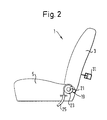
- the pull rope 17 extends from the force limiter 11 below the Seat part 5 to the front and is secured by a rope 18 attached to it a Bowden cable 25 (see FIG. 3) extended, which again after is redirected at the rear, where it is shown on a stylized Tilt adjustment mechanism 19 for the backrest 3, as in Figure 2 is attached.
- the rope 18 is locked on Tilt adjustment mechanism 19 takes place via a not shown lockable coupling between a shaft 21 as part of the Tilt adjustment mechanism 19 and a disc 23 on which the rope 18 is attached.
- the clutch is designed so that it is only when the restraint system is activated, the shaft 21 and the Disk 23 is non-positively coupled.
- Another coupling connects the shaft 21 to the drive in the form of a Handwheels for the tilt adjustment mechanism 19.
- This clutch disengages when the restraint system is activated, the drive from Tilt adjustment mechanism 19 to disrupt the activation to exclude movement sequences caused.
- the traction cable 17 connected to the belt buckle 9 with its Extension forms an actuating device for generating a Adjustment movement for the backrest 3 in the event of a restraint.
- the Actuator that ensures that in the event of a frontal impact the backrest 3 about its pivot axis, namely the center line of the Shaft 21 is pivoted, as explained in detail below receives the energy required to pivot the backrest 3 due to the tensile load introduced into the buckle 9 due to the in the event of a restraint, vehicle occupants moving forward.
- the handwheel drive can be used the tilt adjustment mechanism 19 of the backrest 3 are moved, so that the inclination of the backrest 3 optimally to the size of the Vehicle occupants 27 can be adapted.
- the actuator is in not with the tilt adjustment mechanism 19 coupled.
- the vehicle occupant 27 is then moved back. However, since its back remains on the Backrest 3 rests and the distance between the head and the tracked headrest 29 compared to a not tracked Backrest 3 including headrest 29 is low, the head has a relative low speed when it hits the headrest 29. at So far there has also been a slightly lateral frontal impact Danger that when the vehicle occupant 27 rebounds, its head on the Headrest 29 slides past. With a tracked backrest 3 together with the headrest 29, this risk is significantly lower.
- the tilt adjustment mechanism 19 for the backrest 3 is through the pull rope 17 and the rope 18 not only in the swivel direction front, but also non-positive in the swivel direction to the rear connected to the buckle 9 and the force limiter 11.
- the backrest 3 is not fixed in its foremost position, so that it in the event of an impact due to the displacement of the vehicle occupant 27 pivots backwards (see. Fig. 4d to 4f). This leads to reversal of the movement sequence described with reference to FIGS. 4a to 4c a displacement of the buckle 9 in the direction of that in the figures 4d to 4f arrow shown.
- the forward displacement of the backrest 3 offers not only for the vehicle front passengers increased protection, but also for rear passengers, which can no longer crash against the backrest 3, so that the risk of head injuries to rear passengers is reduced.
- the restraint system shown in FIGS. 5 to 7 is also used the force for adjusting a component of the vehicle seat 1, namely the seat 7, by moving the buckle 9th due to the tensile load introduced into the restraint belt.
- the Traction rope 17 extends from the buckle 9 forward to one pivotally mounted element 33 in the form of a two-armed lever, the extends over almost the entire seat width.
- the pull rope 17 and the element 33 form an actuating device.
- One arm of the lever lies in the non-actuated state of the restraint system on the underside of a Upholstery 35.
- the pull cable 17 is locked on the opposite arm.
- the seat pan 37 is on the underside of an arm of a two-armed Lever 39 on whose opposite arm with the pull rope 17th connected is.
- FIGS. 5 and 6 do not fall under the Scope of protection of the patent.
- the seat adjustments shown in it can but can be used in a restraint system according to the invention, in which the actuating device according to claim 1 with a tilt adjustment mechanism for the backrest and / or one of the Vehicle occupant operated tilt adjustment mechanism for the Stiz Chemistry, the inclination adjustment mechanism the actuator enlarged in the case of retention, connected.
- the pull rope 17 with a seat reclining mechanism 41 coupled.
- a clutch 43, which is between sections of the pull cable 17th is arranged ensures that the seat reclining mechanism 41 only in the event of a vehicle collision with the belt buckle 9 is non-positively connected.
- a coupled with the pull rope 17 Force limiter 11 also provides damping in the Advancing the vehicle occupant in the event of a restraint.
- the Force limiter 11 is only from a certain intensity of Vehicle impact triggered. That means in the case of the one shown in FIG Embodiment that a shift of the traction rope 17 also first takes place from a predetermined intensity of the impact.
- the angle of inclination of the seat 7 by a changed purely mechanical actuating device without it being an additional Energy source needs.
- a rocker arm mechanism can also be provided a linear guide through which, for example a wedge in the front area of the seat part 5 obliquely upwards is moved to the seat 7 in this area upwards to press.
- FIGS. 5 to 7 Restraint system shown in a frontal impact with reference to figure 7 described.
- the vehicle occupant moves relative to the vehicle seat 1 to the front and thereby calls in the seat belt a high tensile load emerges, which initiated in the buckle 9 is so that it is shifted in the direction of the arrow.
- the force limiter 11 allows a displacement of the buckle 9, while the sheathing 15 of the traction cable 17 is plastically deformed so that the Restraint force of the restraint belt exerted on the vehicle occupants is limited. Due to the rapid displacement of the buckle 9 and the attached pull cable 17, the clutch 43 engages, so that a positive connection between the buckle 9 and the seat reclining mechanism 41 is made.
- the entire Seat part 5 pivots clockwise, so that the angle of inclination the seat 7 is enlarged, as with the dash-dotted Lines shown in Figure 7.
- the extent of the adjustment of the Seat 7 depends on the intensity of the vehicle impact, since shifts further forward with higher intensity of the vehicle occupant.
- the steeply inclined rear seat 7 stabilizes the Location of the vehicle occupant in a frontal impact, so that in particular in the case of small vehicle occupants there is a risk that Too much shifting of the pelvic belt in the area of the Abdomen slips, is reduced.
- Embodiments of the restraint system essentially correspond to with reference to the processes described in FIG. 7, whereby according to the embodiment 5 by moving the buckle 9 Element 33 is pivoted counterclockwise so that only the front area of the seat 7 is raised, whereas by the Swiveling the lever 39 according to FIG. 6, the entire seat pan 37 and so that the entire seat 7 is adjusted.
- FIGS. 1 to 4 and in FIGS to 7 shown embodiments of the restraint system exists for Example in that the pull rope 17 after the buckle 9th bifurcates.
- Part of the pull cable 17, that is to say a first actuating device ensures the adjustment of the seat 7 and a second part of the Traction rope 17, that is, a second adjusting device for the adjustment the backrest 3.
Claims (17)
- Système de retenue de passagers, comportant un dispositif de commande, une serrure de ceinture ancrée sur un siège de véhicule et une ceinture de retenue qui est couplée au siège de véhicule (1) par l'intermédiaire de la serrure de ceinture (9), la charge de traction introduite dans le siège de véhicule (1) par l'intermédiaire de la serrure de ceinture en cas de retenue étant convertible par le dispositif de réglage en un mouvement de réglage d'au moins un élément du siège de véhicule (1), caractérisé en ce que le dispositif de commande est relié à un mécanisme de réglage d'inclinaison (19) pour le dossier (3) et/ou à un mécanisme de réglage d'inclinaison (41) pour la surface de siège (7), dont l'angle d'inclinaison est agrandi par le dispositif de commande en cas de retenue.
- Système de retenue selon la revendication 1, caractérisé en ce que le dossier (3) du siège de véhicule (1) est relié au dispositif de commande et est pivoté par celui-ci vers l'avant lors d'une collision frontale de véhicule de sorte qu'il suit le mouvement vers l'avant du passager du véhicule.
- Système de retenue selon la revendication 2, caractérisé en ce que le dossier (3) est réalisé de telle sorte que lors du contrecoup consécutif du passager, il pivote vers l'arrière en raison du déplacement du passager vers l'arrière.
- Système de retenue selon l'une des revendications 1 à 3, caractérisé en ce que le dispositif de commande est réalisé de telle sorte que la plage de pivotement du dossier (3) peut être modifiée en fonction de l'intensité de la collision.
- Système de retenue selon la revendication 4, caractérisé en ce que le dossier (3) est relié à un élément amortisseur (31) qui amortit le mouvement de pivotement du dossier (3) vers l'arrière.
- Système de retenue selon la revendication 5, caractérisé en ce que le dispositif de commande est réalisé de telle sorte qu'il n'est couplé au mécanisme de réglage d'inclinaison (19) pour le dossier (3) que lors de l'activation du système de retenue.
- Système de retenue selon la revendication 6, caractérisé en ce que le dispositif de commande est réalisé de telle sorte que lors de l'activation du système de retenue, un entraínement pour le mécanisme de réglage d'inclinaison (19) est découplé de celui-ci, de sorte que seul le dispositif de commande est couplé au mécanisme de réglage d'inclinaison (19).
- Système de retenue selon l'une des revendications précédentes, caractérisé en ce qu'en cas de retenue, le dispositif de commande agrandit l'angle d'inclinaison de la surface de siège (7).
- Système de retenue selon la revendication 8, caractérisé en ce qu'en cas de retenue, le dispositif de commande est couplé au mécanisme de réglage d'inclinaison (41) pour la surface de siège (7).
- Système de retenue selon la revendication 8 ou 9, caractérisé en ce que le dispositif de commande est réalisé de telle sorte qu'il agrandit l'angle d'inclinaison de toute la partie d'assise (5) du siège de véhicule (1).
- Système de retenue selon la revendication 8 ou 9, caractérisé en ce que le dispositif de commande comprend un élément (33) monté en translation ou à pivotement dans la région antérieure de la partie d'assise (5), qui soulève la région antérieure de la surface de siège (7) lors de l'actionnement du dispositif de réglage.
- Système de retenue selon la revendication 8 ou 9, caractérisé en ce que le dispositif de commande comprend une cuve de siège (37) agencée à pivotement dans la partie d'assise (5) et en ce qu'en pivotant la cuve de siège (37), on agrandit l'angle d'inclinaison de la surface de siège (7) adjacente à celle-ci.
- Système de retenue selon la revendication 12, caractérisé en ce que le dispositif de commande comprend un levier (39) à deux bras, un bras attaquant la cuve de siège (37) et l'autre bras étant relié à un câble de traction (17).
- Système de retenue selon l'une des revendications 8 à 13, caractérisé en ce que l'angle, de la valeur duquel le dispositif de commande modifie l'inclinaison de la surface de siège (7), dépend de l'intensité de la collision du véhicule.
- Système de retenue selon l'une revendications 8 à 14, caractérisé en ce qu'il est prévu un premier dispositif de commande pour le réglage de l'angle d'inclinaison de la surface de siège (7) et un deuxième dispositif de commande pour le réglage de l'angle d'inclinaison du dossier (3).
- Système de retenue selon l'une des revendications précédentes, caractérisé en ce que du côté serrure de ceinture, il est prévu un limiteur de forces (11) qui est couplé au dispositif de commande.
- Système de retenue selon l'une des revendications précédentes, caractérisé en ce que le système de retenue est réalisé de telle sorte qu'il n'est déclenché que lors d'une collision de véhicule avec une intensité prédéterminée.
Applications Claiming Priority (2)
| Application Number | Priority Date | Filing Date | Title |
|---|---|---|---|
| DE29610078U | 1996-06-07 | ||
| DE29610078U DE29610078U1 (de) | 1996-06-07 | 1996-06-07 | Rückhaltesystem für Fahrzeuginsassen |
Publications (2)
| Publication Number | Publication Date |
|---|---|
| EP0811534A1 EP0811534A1 (fr) | 1997-12-10 |
| EP0811534B1 true EP0811534B1 (fr) | 2003-01-02 |
Family
ID=8024918
Family Applications (1)
| Application Number | Title | Priority Date | Filing Date |
|---|---|---|---|
| EP97108374A Expired - Lifetime EP0811534B1 (fr) | 1996-06-07 | 1997-05-23 | Système de retenue des occupants d'un véhicule |
Country Status (6)
| Country | Link |
|---|---|
| US (1) | US5908219A (fr) |
| EP (1) | EP0811534B1 (fr) |
| JP (1) | JPH1059126A (fr) |
| KR (1) | KR980001498A (fr) |
| DE (2) | DE29610078U1 (fr) |
| ES (1) | ES2110387T3 (fr) |
Cited By (1)
| Publication number | Priority date | Publication date | Assignee | Title |
|---|---|---|---|---|
| DE19931894B4 (de) * | 1999-07-08 | 2005-06-30 | Key Safety Systems, Inc., Sterling Heights | Fahrzeugsitz |
Families Citing this family (53)
| Publication number | Priority date | Publication date | Assignee | Title |
|---|---|---|---|---|
| GB2309889B (en) * | 1996-02-06 | 1999-05-26 | Autoliv Dev | Improvements in or relating to a vehicle seat |
| DE19707998B4 (de) * | 1997-02-27 | 2007-04-05 | Inova Gmbh Technische Entwicklungen | Kraftfahrzeugsitz |
| DE19731761A1 (de) * | 1997-07-24 | 1999-01-28 | Rolf Willer | Hochklappendes Sitzpolster bei Sitzen und Sitzbänken in Fahrzeugen aller Art zur Verringerung der Verletzungen von Leber und Milz bei Unfällen |
| FR2772690B1 (fr) * | 1997-12-24 | 2000-02-18 | Faure Bertrand Equipements Sa | Assise d'un siege de vehicule automobile comportant une traverse d'anti-sous-marinage |
| US6062642A (en) * | 1998-04-02 | 2000-05-16 | Volkswagen Ag | Vehicle seat |
| JP3715106B2 (ja) * | 1998-06-16 | 2005-11-09 | 日本発条株式会社 | 車両用シート装置 |
| US6179362B1 (en) * | 1998-08-26 | 2001-01-30 | Johnson Controls Technology Company | Vehicle utility seat |
| JP4080609B2 (ja) * | 1998-09-29 | 2008-04-23 | 日本発条株式会社 | 車両用座席 |
| US6604599B2 (en) * | 1999-03-15 | 2003-08-12 | Nhk Spring Co., Ltd. | Anti-submarine vehicle occupant restraint system |
| DE10011829C2 (de) * | 1999-03-15 | 2002-08-08 | Nhk Spring Co Ltd | Stellantrieb für ein Fahrzeuginsassenrückhaltesystem |
| DE10011817B4 (de) | 1999-03-15 | 2005-05-25 | NHK Spring Co., Ltd., Yokohama | Fahrzeugsitzvorrichtung zum Anheben eines vorderen Sitzteiles |
| FR2796602B1 (fr) * | 1999-07-21 | 2001-10-12 | Faure Bertrand Equipements Sa | Siege d'automobile comportant un mecanisme de reglage en position verrouillable |
| DE19942489B4 (de) * | 1999-09-06 | 2005-03-17 | Siemens Restraint Systems Gmbh | Sitzlehnenrotation |
| US8251444B2 (en) * | 2005-04-25 | 2012-08-28 | Arjuna Indraeswaran Rajasingham | Vehicle occupant support |
| DE19946406B4 (de) * | 1999-09-28 | 2005-03-31 | Siemens Restraint Systems Gmbh | Sicherheitseinrichtung für einen Fahrzeugsitz |
| DE19960087C5 (de) * | 1999-12-14 | 2007-01-25 | Daimlerchrysler Ag | Fahrzeugsitz |
| DE29922856U1 (de) | 1999-12-27 | 2000-05-04 | Trw Repa Gmbh | Fahrzeugsitz |
| JP2001247010A (ja) * | 1999-12-28 | 2001-09-11 | Takata Corp | 乗員保護装置 |
| DE10045399A1 (de) * | 2000-09-14 | 2002-04-04 | Faurecia Autositze Gmbh & Co | Fahrzeugsitz |
| EP1199214B1 (fr) | 2000-10-13 | 2006-06-21 | Nhk Spring Co.Ltd. | Système de retenu avec dispositif d'anti-sousmarinage pour passager de véhicule |
| DE60138352D1 (de) * | 2000-10-13 | 2009-05-28 | Nhk Spring Co Ltd | Fahrzeuginsassen-Rückhaltesystem zur Verhinderung des Abtauches |
| FR2832961B1 (fr) * | 2001-12-03 | 2004-02-13 | Faurecia Sieges Automobile | Siege de vehicule |
| DE10231794A1 (de) * | 2002-07-10 | 2004-02-12 | Takata-Petri Ag | Kraftfahrzeugsitz |
| US6974187B2 (en) * | 2004-01-28 | 2005-12-13 | Tachi-S Co., Ltd. | Vehicle seat structure |
| FR2866610B1 (fr) * | 2004-02-24 | 2007-05-18 | Renault Sas | Siege, notamment pour vehicule automobile |
| DE102004017650B4 (de) * | 2004-04-05 | 2010-07-22 | Takata-Petri Ag | Sicherheitsanordnung für Kraftfahrzeuge |
| FR2875187B1 (fr) * | 2004-09-10 | 2008-03-14 | Faurecia Sieges Automobile | Siege de vehicule automobile comportant une assise reglable en hauteur et un point d'attache d'une ceinture de securite lie a l'assise |
| DE102005007428A1 (de) * | 2005-02-18 | 2006-08-31 | Volkswagen Ag | Fahrzeugsitz für ein Fahrzeug, insbesondere für ein Kraftfahrzeug |
| JP4923529B2 (ja) * | 2005-11-14 | 2012-04-25 | タカタ株式会社 | 乗員拘束装置 |
| JP2007176425A (ja) * | 2005-12-28 | 2007-07-12 | Toyota Motor Corp | 車両制御装置 |
| WO2007091575A1 (fr) * | 2006-02-06 | 2007-08-16 | Ts Tech Co., Ltd. | Siège de véhicule |
| DE102007025436B4 (de) | 2007-05-31 | 2010-07-29 | Daimler Ag | Rückhaltesystem für einen Fahrzeuginsassen |
| EP2003024A1 (fr) * | 2007-06-11 | 2008-12-17 | Dalphi Metal Espana, S.A. | Airbag latéral pour sièges inclinables |
| US8100471B2 (en) * | 2008-03-03 | 2012-01-24 | GM Global Technology Operations LLC | Adjustable seat ramp utilizing active material actuation |
| JP5395457B2 (ja) * | 2009-02-25 | 2014-01-22 | テイ・エス テック株式会社 | 車両用シート |
| JP5486349B2 (ja) * | 2010-03-01 | 2014-05-07 | テイ・エス テック株式会社 | 乗物用シート |
| DE102010052412B4 (de) * | 2010-11-24 | 2017-11-16 | Daimler Ag | Verfahren und Vorrichtung zum Schützen eines Fahrzeuginsassen in einem Fahrzeugsitz eines Fahrzeugs |
| DE102013101540B4 (de) * | 2013-02-15 | 2021-10-07 | Faurecia Autositze Gmbh | Fahrzeugsitz, insbesondere für ein Kraftfahrzeug |
| EP2805850B1 (fr) * | 2013-05-22 | 2016-02-17 | Tachi-S Co., Ltd. | Siège de véhicule |
| JP6173812B2 (ja) * | 2013-07-18 | 2017-08-02 | タカタ株式会社 | 車両用シート |
| US9199560B2 (en) * | 2013-09-13 | 2015-12-01 | Ford Global Technologies, Llc | Self-adjusting seat stiffness system |
| JP6527732B2 (ja) * | 2015-03-24 | 2019-06-05 | Joyson Safety Systems Japan株式会社 | 乗員拘束装置 |
| US9821758B2 (en) | 2016-02-05 | 2017-11-21 | Ford Global Technologies, Llc | Pretensioning, force-limiting seat belt assembly |
| JP7095492B2 (ja) * | 2018-08-27 | 2022-07-05 | トヨタ自動車株式会社 | 車両用シート |
| DE102018124929A1 (de) * | 2018-10-09 | 2020-04-09 | Bayerische Motoren Werke Aktiengesellschaft | Fahrzeugsitzkonsole |
| US10829015B2 (en) | 2018-10-11 | 2020-11-10 | Ford Global Technologies, Llc | Vehicle seat assembly |
| JP7132141B2 (ja) * | 2019-02-04 | 2022-09-06 | トヨタ自動車株式会社 | バックル装置、バックル装置のシート搭載構造、及び車両用シートベルト装置 |
| JP7136728B2 (ja) | 2019-03-15 | 2022-09-13 | トヨタ自動車株式会社 | シートベルト装置 |
| JP6933681B2 (ja) * | 2019-03-22 | 2021-09-08 | オートリブ ディベロップメント エービー | シートベルトバックル装置 |
| US10940776B2 (en) | 2019-04-17 | 2021-03-09 | Ford Global Technologies, Llc | Adjustable seat |
| US11091070B2 (en) | 2019-05-16 | 2021-08-17 | Ford Global Technologies, Llc | Suspension system for vehicle seat |
| US20200398714A1 (en) * | 2019-06-19 | 2020-12-24 | Ford Global Technologies, Llc | Vehicle seating assembly with displaceable platform |
| US20230286426A1 (en) * | 2022-03-14 | 2023-09-14 | Institute For Injury Research | System and method for protecting an occupant in a rear impact of a vehicle |
Family Cites Families (10)
| Publication number | Priority date | Publication date | Assignee | Title |
|---|---|---|---|---|
| US2401748A (en) * | 1944-10-17 | 1946-06-11 | Frederick P Dillon | Aircraft seat supporting structure |
| FR1543275A (fr) * | 1967-07-31 | 1968-10-25 | Peugeot | Nouvel agencement, à absorption d'énergie, d'un siège sur un véhicule |
| FR2201659A5 (fr) * | 1972-10-02 | 1974-04-26 | Peugeot & Renault | |
| DE3237167A1 (de) * | 1982-10-07 | 1984-04-12 | Volkswagenwerk Ag, 3180 Wolfsburg | Fahrzeugsitz |
| JPS61158538U (fr) * | 1985-03-26 | 1986-10-01 | ||
| US4738485A (en) * | 1986-10-16 | 1988-04-19 | Trw Vehicle Safety Systems, Inc. | Seat assembly with occupant restraint system |
| FR2641244B1 (fr) * | 1988-12-30 | 1993-06-18 | Renault | Siege a ceinture de securite pour vehicules automobiles |
| DE4032385C2 (de) * | 1990-10-12 | 1994-06-23 | Audi Ag | Sicherheitseinrichtung für einen Fahrzeuginsassen |
| GB2265813B (en) * | 1992-04-07 | 1995-11-15 | Aerospace Seating Ltd | Crash attenuating seat belt anchorage |
| US5567006A (en) * | 1993-10-01 | 1996-10-22 | Mccarthy; Joseph | Vehicle seat with articulated sections |
-
1996
- 1996-06-07 DE DE29610078U patent/DE29610078U1/de not_active Expired - Lifetime
-
1997
- 1997-05-23 EP EP97108374A patent/EP0811534B1/fr not_active Expired - Lifetime
- 1997-05-23 ES ES97108374T patent/ES2110387T3/es not_active Expired - Lifetime
- 1997-05-23 DE DE59709040T patent/DE59709040D1/de not_active Expired - Fee Related
- 1997-05-27 US US08/863,696 patent/US5908219A/en not_active Expired - Fee Related
- 1997-06-06 JP JP9149125A patent/JPH1059126A/ja active Pending
- 1997-06-12 KR KR1019970024217A patent/KR980001498A/ko not_active Application Discontinuation
Cited By (1)
| Publication number | Priority date | Publication date | Assignee | Title |
|---|---|---|---|---|
| DE19931894B4 (de) * | 1999-07-08 | 2005-06-30 | Key Safety Systems, Inc., Sterling Heights | Fahrzeugsitz |
Also Published As
| Publication number | Publication date |
|---|---|
| DE29610078U1 (de) | 1996-10-02 |
| JPH1059126A (ja) | 1998-03-03 |
| ES2110387T3 (es) | 2003-07-16 |
| US5908219A (en) | 1999-06-01 |
| KR980001498A (ko) | 1998-03-30 |
| ES2110387T1 (es) | 1998-02-16 |
| DE59709040D1 (de) | 2003-02-06 |
| EP0811534A1 (fr) | 1997-12-10 |
Similar Documents
| Publication | Publication Date | Title |
|---|---|---|
| EP0811534B1 (fr) | Système de retenue des occupants d'un véhicule | |
| DE3631881C2 (fr) | ||
| DE10003853B4 (de) | Fahrzeugsitz mit einer beweglichen Sicherheitstraverse | |
| EP0791501B1 (fr) | Siège de véhicule | |
| EP0794085B1 (fr) | Siège de véhicule | |
| DE10011817B4 (de) | Fahrzeugsitzvorrichtung zum Anheben eines vorderen Sitzteiles | |
| DE60008205T2 (de) | Einrichtung zum Schutz der Insassen | |
| EP0552160B1 (fr) | Dispositif de securite pour vehicules | |
| DE19853981B4 (de) | Kraftfahrzeugsitz | |
| DE2338026C3 (de) | Aufprallschutzvorrichtung für den Fahrer eines Kraftfahrzeuges | |
| DE102011108918B4 (de) | Rückhaltevorrichtung für ein Kraftfahrzeug | |
| EP0786373A2 (fr) | Siège de véhicule | |
| DE10251258A1 (de) | Sitz eines Kraftfahrzeugsitzes mit einer Querstrebe gegen das Darunterhindurchrutschen | |
| DE10302713A1 (de) | Vierpunkt-Sicherheitsgurtrückhaltesystem | |
| DE102018204461A1 (de) | Fahrzeugsitz | |
| DE102011122203A1 (de) | Rückhaltevorrichtung für ein Kraftfahrzeug | |
| DE102018130323B4 (de) | Fahrzeugsitz | |
| WO2019180213A1 (fr) | Ensemble formant siège de véhicule | |
| DE60025984T2 (de) | Einrichtung zum Schutz der Insassen | |
| DE60206695T2 (de) | Kraftfahrzeug Insassenschutzsystem | |
| DE60121278T2 (de) | Personenschutzsystem im Kraftfahrzeug | |
| EP1072485A2 (fr) | Système de ceinture de sécurité | |
| DE60025985T2 (de) | Einrichtung zum Schutz der Insassen | |
| DE10030549B4 (de) | Fahrzeugsitz | |
| WO2018202802A1 (fr) | Siège de véhicule |
Legal Events
| Date | Code | Title | Description |
|---|---|---|---|
| PUAI | Public reference made under article 153(3) epc to a published international application that has entered the european phase |
Free format text: ORIGINAL CODE: 0009012 |
|
| AK | Designated contracting states |
Kind code of ref document: A1 Designated state(s): DE ES FR GB IT SE |
|
| ITCL | It: translation for ep claims filed |
Representative=s name: DR. ING. A. RACHELI & C. |
|
| GBC | Gb: translation of claims filed (gb section 78(7)/1977) | ||
| REG | Reference to a national code |
Ref country code: ES Ref legal event code: BA2A Ref document number: 2110387 Country of ref document: ES Kind code of ref document: T1 |
|
| EL | Fr: translation of claims filed | ||
| 17P | Request for examination filed |
Effective date: 19980203 |
|
| RAP1 | Party data changed (applicant data changed or rights of an application transferred) |
Owner name: TRW OCCUPANT RESTRAINT SYSTEMS GMBH & CO. KG |
|
| 17Q | First examination report despatched |
Effective date: 20000426 |
|
| GRAG | Despatch of communication of intention to grant |
Free format text: ORIGINAL CODE: EPIDOS AGRA |
|
| GRAG | Despatch of communication of intention to grant |
Free format text: ORIGINAL CODE: EPIDOS AGRA |
|
| GRAH | Despatch of communication of intention to grant a patent |
Free format text: ORIGINAL CODE: EPIDOS IGRA |
|
| GRAH | Despatch of communication of intention to grant a patent |
Free format text: ORIGINAL CODE: EPIDOS IGRA |
|
| GRAA | (expected) grant |
Free format text: ORIGINAL CODE: 0009210 |
|
| AK | Designated contracting states |
Kind code of ref document: B1 Designated state(s): DE ES FR GB IT SE |
|
| REG | Reference to a national code |
Ref country code: GB Ref legal event code: FG4D Free format text: 20030102:NOT ENGLISH |
|
| REF | Corresponds to: |
Ref document number: 59709040 Country of ref document: DE Date of ref document: 20030206 Kind code of ref document: P |
|
| PGFP | Annual fee paid to national office [announced via postgrant information from national office to epo] |
Ref country code: GB Payment date: 20030401 Year of fee payment: 7 |
|
| PG25 | Lapsed in a contracting state [announced via postgrant information from national office to epo] |
Ref country code: SE Free format text: LAPSE BECAUSE OF FAILURE TO SUBMIT A TRANSLATION OF THE DESCRIPTION OR TO PAY THE FEE WITHIN THE PRESCRIBED TIME-LIMIT Effective date: 20030402 |
|
| GBT | Gb: translation of ep patent filed (gb section 77(6)(a)/1977) |
Effective date: 20030410 |
|
| REG | Reference to a national code |
Ref country code: ES Ref legal event code: FG2A Ref document number: 2110387 Country of ref document: ES Kind code of ref document: T3 |
|
| ET | Fr: translation filed | ||
| PLBE | No opposition filed within time limit |
Free format text: ORIGINAL CODE: 0009261 |
|
| STAA | Information on the status of an ep patent application or granted ep patent |
Free format text: STATUS: NO OPPOSITION FILED WITHIN TIME LIMIT |
|
| 26N | No opposition filed |
Effective date: 20031003 |
|
| PGFP | Annual fee paid to national office [announced via postgrant information from national office to epo] |
Ref country code: FR Payment date: 20040503 Year of fee payment: 8 |
|
| PG25 | Lapsed in a contracting state [announced via postgrant information from national office to epo] |
Ref country code: GB Free format text: LAPSE BECAUSE OF NON-PAYMENT OF DUE FEES Effective date: 20040523 |
|
| PGFP | Annual fee paid to national office [announced via postgrant information from national office to epo] |
Ref country code: ES Payment date: 20040524 Year of fee payment: 8 |
|
| GBPC | Gb: european patent ceased through non-payment of renewal fee |
Effective date: 20040523 |
|
| PG25 | Lapsed in a contracting state [announced via postgrant information from national office to epo] |
Ref country code: IT Free format text: LAPSE BECAUSE OF NON-PAYMENT OF DUE FEES;WARNING: LAPSES OF ITALIAN PATENTS WITH EFFECTIVE DATE BEFORE 2007 MAY HAVE OCCURRED AT ANY TIME BEFORE 2007. THE CORRECT EFFECTIVE DATE MAY BE DIFFERENT FROM THE ONE RECORDED. Effective date: 20050523 |
|
| PG25 | Lapsed in a contracting state [announced via postgrant information from national office to epo] |
Ref country code: ES Free format text: LAPSE BECAUSE OF NON-PAYMENT OF DUE FEES Effective date: 20050524 |
|
| PGFP | Annual fee paid to national office [announced via postgrant information from national office to epo] |
Ref country code: DE Payment date: 20050531 Year of fee payment: 9 |
|
| PG25 | Lapsed in a contracting state [announced via postgrant information from national office to epo] |
Ref country code: FR Free format text: LAPSE BECAUSE OF NON-PAYMENT OF DUE FEES Effective date: 20060131 |
|
| REG | Reference to a national code |
Ref country code: FR Ref legal event code: ST Effective date: 20060131 |
|
| REG | Reference to a national code |
Ref country code: ES Ref legal event code: FD2A Effective date: 20050524 |
|
| PG25 | Lapsed in a contracting state [announced via postgrant information from national office to epo] |
Ref country code: DE Free format text: LAPSE BECAUSE OF NON-PAYMENT OF DUE FEES Effective date: 20061201 |