EP0810570B1 - Système de navigation indiquant la distance à des embouteillages - Google Patents
Système de navigation indiquant la distance à des embouteillages Download PDFInfo
- Publication number
- EP0810570B1 EP0810570B1 EP97303716A EP97303716A EP0810570B1 EP 0810570 B1 EP0810570 B1 EP 0810570B1 EP 97303716 A EP97303716 A EP 97303716A EP 97303716 A EP97303716 A EP 97303716A EP 0810570 B1 EP0810570 B1 EP 0810570B1
- Authority
- EP
- European Patent Office
- Prior art keywords
- traffic
- traffic jam
- distance
- voice
- jam location
- Prior art date
- Legal status (The legal status is an assumption and is not a legal conclusion. Google has not performed a legal analysis and makes no representation as to the accuracy of the status listed.)
- Expired - Lifetime
Links
Images


Classifications
-
- G—PHYSICS
- G08—SIGNALLING
- G08G—TRAFFIC CONTROL SYSTEMS
- G08G1/00—Traffic control systems for road vehicles
- G08G1/09—Arrangements for giving variable traffic instructions
- G08G1/0962—Arrangements for giving variable traffic instructions having an indicator mounted inside the vehicle, e.g. giving voice messages
- G08G1/0967—Systems involving transmission of highway information, e.g. weather, speed limits
- G08G1/096708—Systems involving transmission of highway information, e.g. weather, speed limits where the received information might be used to generate an automatic action on the vehicle control
- G08G1/096716—Systems involving transmission of highway information, e.g. weather, speed limits where the received information might be used to generate an automatic action on the vehicle control where the received information does not generate an automatic action on the vehicle control
-
- G—PHYSICS
- G08—SIGNALLING
- G08G—TRAFFIC CONTROL SYSTEMS
- G08G1/00—Traffic control systems for road vehicles
- G08G1/09—Arrangements for giving variable traffic instructions
- G08G1/091—Traffic information broadcasting
- G08G1/093—Data selection, e.g. prioritizing information, managing message queues, selecting the information to be output
-
- G—PHYSICS
- G08—SIGNALLING
- G08G—TRAFFIC CONTROL SYSTEMS
- G08G1/00—Traffic control systems for road vehicles
- G08G1/09—Arrangements for giving variable traffic instructions
- G08G1/091—Traffic information broadcasting
- G08G1/094—Hardware aspects; Signal processing or signal properties, e.g. frequency bands
-
- G—PHYSICS
- G08—SIGNALLING
- G08G—TRAFFIC CONTROL SYSTEMS
- G08G1/00—Traffic control systems for road vehicles
- G08G1/09—Arrangements for giving variable traffic instructions
- G08G1/0962—Arrangements for giving variable traffic instructions having an indicator mounted inside the vehicle, e.g. giving voice messages
- G08G1/0967—Systems involving transmission of highway information, e.g. weather, speed limits
- G08G1/096733—Systems involving transmission of highway information, e.g. weather, speed limits where a selection of the information might take place
- G08G1/09675—Systems involving transmission of highway information, e.g. weather, speed limits where a selection of the information might take place where a selection from the received information takes place in the vehicle
-
- G—PHYSICS
- G08—SIGNALLING
- G08G—TRAFFIC CONTROL SYSTEMS
- G08G1/00—Traffic control systems for road vehicles
- G08G1/09—Arrangements for giving variable traffic instructions
- G08G1/0962—Arrangements for giving variable traffic instructions having an indicator mounted inside the vehicle, e.g. giving voice messages
- G08G1/0967—Systems involving transmission of highway information, e.g. weather, speed limits
- G08G1/096766—Systems involving transmission of highway information, e.g. weather, speed limits where the system is characterised by the origin of the information transmission
- G08G1/096775—Systems involving transmission of highway information, e.g. weather, speed limits where the system is characterised by the origin of the information transmission where the origin of the information is a central station
Definitions
- the present invention relates to a navigation system that is capable of reporting traffic control information and traffic jam information transmitted from the outside of the vehicle to the driver by voice.
- Navigation systems that display traffic information sent through an FM multiplex broadcast wave, a light beacon or a radio wave beacon on a display screen using graphics or text are known. Also known are navigation systems which, by setting a route from the current vehicle position to a destination, provide course guidance along the course at guide points such as intersections. In such navigation systems, if there is, for instance, a location where lane traffic control is being implemented, an access ramp is closed or the traffic is jammed on the route that has been set, it is desirable to report that information promptly by voice to the driver.
- DE-A-43 22 288 discloses a system in which traffic messages are transmitted via a radio link to a vehicle fitted with a GPS navigation system, and the messages are communicated to the driver of the vehicle through a voice output device. The traffic messages are filtered so that only messages relevant to the route being followed by the vehicle are fed to the voice output device.
- DE-A- 44 45 582 discloses a similar system in which the received messages are filtered in relation to traffic disturbances which occur within a predetermined area around the current location of the vehicle.
- a navigation system comprising: route setting means for setting a route to a destination; a position detection device that detects a current position; a reception device that receives traffic information from outside; a voice output device that outputs by voice data relating to the received traffic information; and a reporting device responsive to the current position detected by the position detecting device and the traffic information received by the reception device to control operation of the voice output device, wherein the voice output device is configured to output by voice a distance from said current position to a traffic jam or a traffic control point; and the reporting device is operable, when said traffic information received by said reception device indicates that there are a plurality of traffic jams or traffic control points at different jam or control locations along the route set by the route setting means, to determine which of the jam or control locations along the set route is closest to the current location, and to cause said voice output device to selectively output a distance to the jam or control location that is determined to be nearest said current position.
- the distance to the traffic jam location may be reported together with the length of the jam.
- the number of messages voiced to the driver is substantially reduced thereby reducing the risk of irritation to the driver.
- the driver since, when a traffic jam location or a traffic control point is present on a recommended route, the information on the traffic jam location or the traffic control point, which is constituted of text and graphic data (including the information on distance from the current position) is output by voice, the driver can ascertain the traffic jam location or the traffic control point on the recommended route without having to look at a display screen.
- an advantage is achieved in that a traffic jam location is reported to the driver well before the vehicle comes upon it, allowing ample time for the driver to deliberate upon whether or not it is preferable to make a detour and to choose a detour route well in advance.
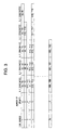
- FIG. 1 is a block diagram of an embodiment of the navigation system according to the present invention.
- the navigation system is provided with a current position detection device that detects the current position of the vehicle and, in this example, the current position detection device is constituted with a gyroscope 1a that detects a travelling direction of the vehicle, a signal processing circuit 1b that processes signals from the gyroscope 1a, a vehicle speed sensor 1c that outputs a vehicle speed signal that corresponds to the vehicle speed, a signal processing circuit 1d that processes a signal from the vehicle speed sensor 1c and a GPS receiver le that receives a GPS signal from a GPS (Global Positioning System) satellite.
- Reference number 2a indicates a CD ROM drive that reads planar road map data that are stored in a CD ROM 2b and reference number 2c indicates a CD ROM interface circuit.
- Reference number 3 indicates a computer that controls the overall operation of the apparatus, comprising a CPU, RAM, ROM and other peripheral circuits .
- the RAM data for planar road map drawing data, image data for display at a display 5a and various types of data tables for displaying and outputting by voice received traffic information are stored.
- the data for map drawing are created based upon 2-dimensional road map data that are read out from the CD ROM 2b and the image data are created from data for planar map drawing and graphic data representing various types of traffic information.
- the image data are read out as necessary and displayed on the display 5a.
- the data tables are created based upon received traffic information.
- Reference number 4a indicates an input device provided with various switches and reference number 4b indicates a signal processing circuit that processes switch signals from the input switches 4a.
- the input device 4a is provided with a voice request switch and other various switches. It is to be noted that the display 5a is connected to and controlled by a display circuit 5b and that various types of touch panel switches are arranged on the display screen of the
- Reference number 6 indicates an FM multiplex receiver that receives traffic information through FM multiplex broadcast waves (hereafter referred to as VICS information).
- VICS information explained in this specification includes traffic jam information and traffic control information.
- the traffic jam information is classified into four types, i.e., jammed (traffic jam data classification 3), congested (2), no jam or congestion with traffic flowing smoothly (traffic jam data classification 1) and unknown (traffic jam data classification 0), and these traffic states, i.e., jammed, congested, and flowing smoothly are respectively displayed in red, yellow and green with a road divided into lanes going in both directions.
- the traffic control information includes road block information (traffic control data classification 1), ramp closure information on access ramps of a highway (traffic control data classification 2) and no traffic control (traffic control data classification 0). It may include lane traffic control information as well.
- VICS information is constituted of the distance from link start points to the tail end of a traffic jam, the distance from the link start point to the front end of the traffic jam, the traffic jam data classification, the distance from the link start point to a traffic control point, the traffic control data classification and the like in correspondence to mesh numbers and link numbers that constitute a road map data.
- Reference number 7a indicates a speaker for issuing a voice report of the distance to the traffic jam location and the distance to the traffic control point, whereas reference number 7b indicates a voice synthesizing circuit and an amplifier.
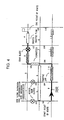
- FIGS. 2 and 3 illustrate the road map data.
- a road R1 intersects two roads R2 and R3.
- the intersection of the road R1 and the road R2 is referred to as a node N1 and the intersection of the road R1 and the road R3 is referred to as a node N2, with the section having the nodes N1 and N2 as its start point and end point respectively referred to as a link 1.
- Interpolation points A1-A3 are provided between the node N1 and the node N2.
- the nodes N1 and N2 and the interpolation points A1-A3 respectively are provided with coordinate position data (X2, Y2)-(X6, Y6), distance data on the distances between the individual points, link length data and the like.
- a road map is divided into a plurality of areas and each divided area is defined by an inherent mesh number.
- the road R1 inside a divided map area defined by a specific mesh number (533946, for instance) is constituted of 100 links
- the road R1 is defined as shown in FIG. 3, by link numbers 1-100, the number of points of nodes and interpolation points constituting each link and the X, Y coordinates of each point.
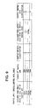
- FIG. 3 shows a road data table for one mesh. It is to be noted that link numbers and node numbers are assigned in each mesh area from 1-a specific number.
- FIG. 4 shows a recommended route RR having a start point and an end point set within the same mesh indicated by bold lines with both traffic jam locations and traffic control points as received by the FM multiplex receiver 6.
- the figure shows a situation in which the recommended route RR is set in the order of link numbers 9, 10, 106, 105, 3 and 4 with traffic jam locations present at link numbers 10 and 3, a congested location present at link number 105 and a smooth traffic flow location present at link number 4. It also shows that there is a road block at link number 3. There are traffic jam locations and traffic control points at links that are not on the recommended route.
- the individual tables, which are to be explained below, are prepared based upon this illustrated example.
- FIGS. 11-19 are flowcharts illustrating various types of processing performed by the computer 3, and the operation of this embodiment is explained in reference to these flowcharts. It is to be noted that the computer 3 executes the program illustrated by the flowcharts in FIGS. 11-19 when the key is operated to the ignition ON position.
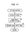
- FIG. 11 is a flowchart of the processing in which a recommended route is set in conformance to an input destination.
- step S1 the recommended route from the current position to the destination is calculated and set.
- the destination is set by the operator via the input device 4 and the recommended route is set automatically through calculations employing a method in the known art such as the Dykstra method.
- the position detected by the current position detection device can be used as the current position. Or, with candidates for a recommended route stored in memory in advance in a ROM or the like, one of these may be selected as a recommended route.
- step S2 data of the recommended route are stored in a specific area of the RAM in the computer 3 and a recommended route data table is created.
- step S3 data on course guidance at guide points on the recommended route are stored in RAM at the computer 3 and a guide point table is created.
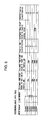
- FIG. 5 shows an example of a recommended route data table.
- the recommended route data table is basically constituted with mesh numbers and link numbers stored sequentially, starting from the current position toward the destination. For instance, in FIG. 5, the recommended route is indicated by link number 9, link number 10, link number 106 ⁇ link number 4 within one mesh area.
- link number 9 link number 10
- link number 106 link number 106 ⁇ link number 4 within one mesh area.
- data on the distance from the link start point to the tail end of a traffic jam location, data on the distance from the link start point to the front end of a traffic jam location, the traffic jam data classification, the distance from the start point to the traffic control point and the traffic control data classification are stored.
- FIG. 6 shows an example of a guide point table.
- the guide point table is constituted of data on the distance from start point of the recommended route to guide points and data on directions for providing course guidance at each guide point.
- FIG. 12 is a flowchart illustrating the traffic information reception processing.
- the traffic information data received by the FM multiplex broadcast receiver 6 are explained.
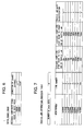
- FIG. 7 shows an example of the traffic jam information provision table, and in correspondence to the individual link numbers combined with a mesh number, the distance from link start points to the tail end of the traffic jam location, the distance from a link start point to the front end of the traffic jam location and the traffic jam data classification are stored. In addition, the number of sets of data is also stored.
- FIG. 8 shows an example of the traffic control information provision table, and in correspondence to the individual link numbers in combination with a mesh number, the distance from link start points to the traffic control point and the traffic control data classification are stored. In addition, the number of sets of data is also stored.
- step S11 if it is decided in step S11, that a recommended route has been set, the operation proceeds to step S12, in which a decision is made as to whether or not the traffic information that has been received includes traffic jam information. If an affirmative decision is made in step S12, the traffic jam information is stored in the recommended route data table in step S13. Step S13 is to be explained later in further detail in reference to FIG. 13.
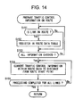
- step S14 a decision is made as to whether or not the received traffic information includes traffic control information. If an affirmative decision is made in step S14, the traffic control information is stored in the recommended route data table in step S15. Step S15 is to be explained later in further detail in reference to FIG. 14.
- step S11 if a recommended route has not been set, a negative decision is made in step S11, whereas if no traffic jam information is present, a negative decision is made in step S12 and if no traffic control information is present, a negative decision is made in step S15.
- FIG. 13 is a detailed flowchart of the processing in which the traffic jam information with respect to traffic jams on the recommended route is registered in step S13 in FIG. 12.
- step S131 a decision is made as to whether or not the link number with the traffic jam data classification that has been received is a link number on the recommended route. If an affirmative decision is made, the operation proceeds to step S132, in which, in correspondence to the relevant mesh number and the relevant link number, the distance from the link start point to the tail end of the traffic jam, the distance from the link start point to the front end of the traffic jam and the traffic jam data classification are stored. If a negative decision is made in step S131, the operation skips step 132. In step 133, a decision is made as to whether or not the processing described above has been completed for all the traffic jam information that has been received, and if the entire information has been checked, the operation proceeds to step S134.
- step S134 the distances from each link start point to the tail end and to the front end of a traffic jam are each converted to a distance from the start point of the recommended route. If it is decided that the conversion processing is completed for all the links in step S135, this processing ends.
- the recommended route data table shown in FIG. 5 is a table resulting from this processing. It indicates that, for instance, the traffic jam information is unknown and no traffic control is being implemented for link number 9, that a traffic jam location is present but no traffic control is being implemented for link number 10, that there is a congested location but no traffic control point is present for link number 105, that a traffic jam location is present and that a road block traffic control is also being implemented for link number 3 and that traffic is flowing smoothly and no traffic control is being implemented for link number 4.
- FIG. 14 is a detailed flowchart of the processing in which the traffic control information with respect to traffic control being implemented on the recommended route is registered in step S15, as shown in FIG. 12.
- step S151 a decision is made as to whether or not the link number with the traffic control data classification that has been received is a link number on the recommended route. If an affirmative decision is made, the operation proceeds to step S152, in which, in correspondence to the relevant mesh number and the relevant link number, the distance from the link start point to the traffic control point and the traffic control data classification are stored. If a negative decision is made in step S151, the operation skips step S152.
- step S153 a decision is made as to whether or not the processing described above has been completed for all the traffic control information that has been received, and if a check on the entire information has been completed, the operation proceeds to step S154, in which the distance from each link start point to the traffic control point is converted to a distance from the start point of the recommended route. This processing ends if, in step S155 it is decided that the conversion processing has been completed for all the links.
- FIG. 9 shows an example of a traffic jam / traffic control data table in which the distance from the start point of the recommended route to the tail end of the traffic jam location, the length of the traffic jam, the traffic jam data classification, the distance from the start point of the recommended route to the traffic control point and the traffic control data classification are stored.
- the distance from the start point of the recommended route to the tail end of a traffic jam location can be calculated based upon the data on the lengths of the individual links constituting the recommended route and the distance from the start point of the link where the traffic jam location is situated and the tail end of the traffic jam.
- the length of the traffic jam can be calculated based upon the distance from the link start point to the tail end of the traffic jam and the distance from the link start point to the front end.
- the distance from the start point of the recommended route to a traffic control point can be determined in a similar manner.
- FIG. 10 shows specific details of the traffic jam / traffic control data table shown in FIG. 9, indicating the distances from the start point of the recommended route to the tail end of the traffic jam location and the distance to the traffic control point as well as the length of the traffic jam.
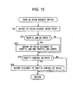
- FIG. 15 is a flowchart of the processing performed when the voice request switch is operated.
- the guide point table shown in FIG. 6 is searched and the course guidance direction at the guide point that is nearest the current position is output from the speaker 7b via the voice synthesizing circuit and amplifier 7a in step S21. If it is decided that there is a traffic jam location on the recommended route in step S22, the operation proceeds to step S23, in which the distance from the current position to the tail end of the traffic jam and the length of the traffic jam are output by voice. If it is decided that there is a traffic control point on the recommended route in step S24, the operation proceeds to step S25, in which the distance from the current position to the traffic control point is output by voice. If there is no traffic jam location or traffic control point, negative decisions are made in steps S22 and S24 and no voice output is performed.
- FIG. 16 is a flowchart of the processing that is performed for each specific traveling distance, i.e., every 10m, for instance. If it is decided in step S31 that a recommended route has been set, a decision is made in step S32 as to whether or not the vehicle is traveling on the recommended route that has been set. If it is traveling on the recommended route, the distance from the start point of the recommended route to the current position on the recommended route is calculated in step S33. If it is decided in step S34 that there is a traffic jam location on the recommended route, a decision is made as to whether or not the current position is within the traffic jam location in step S35. If the current position is not within the traffic jam location, the conditions for issuing a voice report on the traffic jam are checked in step S36. This check will be explained in detail later in reference to FIGS. 17A and 17B. If the current position is within the traffic jam location, the distance from the current position to the front end of the traffic jam is reported by voice in step S43.
- step S37 a decision is made as to whether or not a voice report flag, which is turned on/off through the condition check processing for voice reporting on a traffic jam shown in FIGS. 17A and 17B, is on.
- a voice report flag which is turned on/off through the condition check processing for voice reporting on a traffic jam shown in FIGS. 17A and 17B.
- the voice report flag is turned off when voice output is prohibited and the voice report flag is turned on when voice output is allowed.
- step S37 If the voice report flag is on in step S37, the distance from the current position to the tail end of the traffic jam location and the length of the traffic jam are reported by voice in step S38. Then, if it is decided that there is a traffic control point on the recommended route in step S39, the conditions for issuing a voice report on the traffic control point are checked in step S40. This check will be explained in further detail later in reference to FIGS . 18A and 18B.
- step S41 a decision is made as to whether or not the voice report flag, which is turned on/off through the condition check processing for voice reporting on a traffic control point shown in FIGS. 18A and 18B, is on.
- the voice report flag is turned off when voice output is prohibited and the voice report flag is turned on when voice output is allowed. If the voice report flag is on in step S41, the distance from the current position to the traffic control point is reported by voice in step S42. In regard to traffic control points, even when there are a plurality of traffic control points, only the distance from the current position to the nearest traffic control point is reported by voice output.
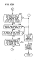
- FIGS. 17A and 17B are flowcharts that illustrate the condition check processing for voice reporting on traffic jam locations in further detail. If it is decided in step S361 that a traffic control point is present preceding a traffic jam location that is ahead of the current position, the voice report flag is turned off in step S375, and in step S376, a specific value is added to a distance counter. This distance counter measures the distance traveled from the point in time at which a voice output is first performed for a traffic jam location up to the present time.
- step S361 the operation proceeds to step S362, in which a decision is made as to whether or not the information on a traffic jam location on the recommended route has been received for the first time. If the information has been received for the first time, the voice report flag is turned on in step S371, and in step S372, the distance from the current position to the tail end of the traffic jam location is stored in memory. Then, in step S373, the distance counter is cleared and in step S374, the timer is cleared. This timer counts the length of time elapsing from the point at which a voice output on a traffic jam location is issued for the first time up to the current time.
- step S362 If a negative decision is made in step S362, a decision is made in step S363 as to whether or not the previous distance to the tail end of the traffic jam was equal to or greater than 50km and the current distance is less than 50km, and if a negative decision is made in step S363, the operation proceeds to step S364.
- step S364 a decision is made as to whether or not the previous distance to the tail end of the traffic jam was equal to or greater than 10km and the current distance is less than 10km. If a negative decision is made in step S364, a decision is made in step S365 as to whether or not the previous distance to the tail end of the traffic jam was equal to or greater than 2km and the current distance is less than 2km.
- step S365 a decision is made in step S366 as to whether or not there is a difference of 10km or more between the distance to the tail end of the previously reported traffic jam location and the distance to the tail end of a traffic jam location that has occurred at a point close to the vehicle position and has been newly detected in step S34.
- step S367 a decision is made as to whether or not there is a difference of 2km or more between the previously reported distance to the tail end of the traffic jam location and the newly calculated distance to the tail end of the same traffic jam location. If a negative decision is made in step S367, the voice report flag is turned off in step S375. If, on the other hand, an affirmative decision is made in step S367, the operation proceeds to step S368, in which a decision is made as to whether or not the vehicle has traveled 5km or more from the point at which the previous voice report was issued. If a negative decision is made, the voice report flag is turned off in step S375.
- step S368 the operation proceeds to step 5369, in which a decision is made as to whether or not 10 minutes or more have elapsed since the point in time at which the previous voice report was issued. If a negative decision is made, the voice report flag is turned off in step S375, whereas if an affirmative decision is made in step S369, the operation proceeds to step S370, in which a decision is made as to whether or not the distance from the current position to the tail end of the traffic jam is at or less than 100km, and if a negative decision is made, the voice report flag is turned off in step S375. If an affirmative decision is made in step S370, the operation proceeds to step S371. The processing from step S367 through step S370 described above is performed to ensure that voice output is not performed indiscriminately since, if voice reporting is performed too frequently, it can become irritating.
- FIGS. 18A and 18B is flowcharts that illustrate the condition check processing for voice reporting on traffic control points in further detail.
- step S411 a decision is made as to whether or not information on a traffic control point on the recommended route has been received for the first time. If the information has been received for the first time, the voice report flag is turned on in step S419, and in step S420, the distance to the traffic control point is stored in memory. Then, in step S421, the distance counter is cleared and in step S422, the timer is cleared.
- step S411 a decision is made in step S412 as to whether or not the previous distance to the traffic control point was equal to or greater than 50km and the current distance is less than 50km, and if a negative decision is made in step S412, the operation proceeds to step S412.
- step S413 a decision is made as to whether or not the previous distance to the traffic control point was equal to or greater than 10km and the current distance is less than 10km. If a negative decision is made in step S413, a decision is made in step S414 as to whether or not the previous distance to the traffic control point was equal to or greater than 2km and the current distance is less than 2km. If a negative decision is made in step S414, a decision is made in step S415 as to whether or not there is a difference of 10km or more between the previous distance to the traf f ic control point and the current distance to the traffic control point.
- step S416 in which a decision is made as to whether or not there is a difference of 2km or more between the previous distance to the traffic control point and the current distance to the traffic control point. If a negative decision is made in step S416, the voice report flag is turned off in step S423, and a specific value is added onto the distance counter in step S424.
- step S417 in which a decision is made as to whether or not the vehicle has traveled 5km or more from the point at which the previous voice report was issued. If a negative decision is made, the voice report flag is turned off in step S423. If, on the other hand, an affirmative decision is made in step S417, the operation proceeds to step S418, in which a decision is made as to whether or not 10 minutes or more have elapsed since the point in time at which the previous voice report was issued. If a negative decision is made, the voice report flag is turned off in step S423. If an affirmative decision is made in step S418, the operation proceeds to step S419.
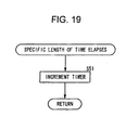
- FIG. 19 is a flowchart showing the interrupt processing that is performed over specific time intervals.
- step S51 the timer counter is incremented by a specific value.
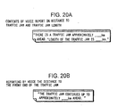
- the distance from the current position to a traffic jam location and the length of the traffic jam are reported by voice as shown in FIG. 20A
- the distance from the current position to the front end of the traffic jam is reported by voice as shown in FIG. 20B when the current position is within a traffic jam location
- the distance from the current position to a traffic control point is reported by voice as shown in FIG. 20C
- the distance from the current position to a location where an access ramp is closed is reported by voice as shown in FIG. 20D
- the direction of the course at a guide point is reported by voice as shown in FIG. 20E.
- the information on traffic jam locations and traffic control points is reported by voice in the following manner.
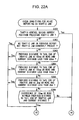
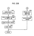
- FIGS. 21A, 21B 22A and 22B show examples of a flowchart of the interrupt processing performed at intervals of a specific distance traveled and a flowchart of the condition check processing for voice reporting on traffic jam locations that is performed in such cases.
- FIGS. 21A and 21B which correspond to FIG. 16, are flowcharts of the processing that is executed every time the vehicle covers a distance of 10m.
- the difference from the processing shown in FIG. 16 is the decision making performed in step S38A.
- step S38A a decision is made as to whether or not there is a traffic jam location present at or within 100km from the current position for which a voice report has not yet been issued and if there is one, the operation returns to step S38, in which the distance to the tail end of the traffic jam location and the length of the traffic jam are reported by voice.
- a voice report is issued on every traffic jam location that is present at or within 100km.
- the distance By setting the distance at a large value such as 2000km instead of 100km, all traffic jam information can be reported by voice.
- FIGS. 22A and 22B which correspond to FIGS. 17A and 17B, are flowcharts of the condition check processing for voice reporting of traffic jam information.
- the difference from the processing shown in FIGS. 17A and 17B are that the decision making performed in steps S367-370 for preventing voice output that may be irritating is omitted.
- voice output is performed in conformance to the decisions made in regard to the voice output conditions performed in steps S361 - 366, whereas if the conditions are not satisfied, no voice output is performed.
Landscapes
- Physics & Mathematics (AREA)
- General Physics & Mathematics (AREA)
- Life Sciences & Earth Sciences (AREA)
- Atmospheric Sciences (AREA)
- Engineering & Computer Science (AREA)
- Multimedia (AREA)
- Signal Processing (AREA)
- Navigation (AREA)
Claims (14)
- Système de navigation, comprenant :un moyen d'établissement d'itinéraire pour établir un itinéraire jusqu'à une destination ;un dispositif de détection (1) de position qui détecte une positon instantanée ;un dispositif de réception (6) qui reçoit de l'extérieur des informations sur la circulation ;un dispositif de sortie vocale (7) qui délivre vocalement des données concernant les informations reçues sur la circulation ; etun dispositif de signalisation (3) réagissant à la position instantanée détectée par le dispositif de détection de position et aux informations sur la circulation reçues par le dispositif de réception afin de commander le fonctionnement du dispositif de sortie vocale, caractérisé en ce quele dispositif de sortie vocale (7) est agencé pour délivrer vocalement une distance de ladite position instantanée à un embouteillage ou un point de régulation de la circulation ; etle dispositif de signalisation (3) sert, lorsque lesdites informations sur la circulation reçues par ledit dispositif de réception indiquent qu'il y a plusieurs embouteillages ou points de régulation de circulation en différents points d'embouteillage ou de régulation sur l'itinéraire établi par le moyen d'établissement d'itinéraire, à déterminer celui des points d'embouteillage ou de régulation sur l'itinéraire établi qui se trouve le plus près de la position instantanée, et à amener ledit dispositif de sortie vocale à délivrer de manière sélective une distance au point d'embouteillage ou de régulation qui est déterminée comme étant la plus proche de ladite position instantanée.
- Système de navigation selon la revendication 1, dans lequel :ledit dispositif de signalisation (3) est configuré pour signaler également la longueur dudit embouteillage.
- Système de navigation selon la revendication 1 ou 2, dans lequel le dispositif de signalisation (3) peut fonctionner de manière sélective dans un mode tel que, lorsque lesdites informations sur la circulation reçues par ledit dispositif de réception indiquent qu'il y a plusieurs embouteillages ou points de régulation de circulation, ledit dispositif de sortie vocale est amené à délivrer toutes les distances de ladite position instantanée à ladite pluralité de points.
- Système de navigation selon l'une quelconque des revendications précédentes, dans lequel le dispositif de signalisation (3) est utilisable dans un mode tel que, lorsque les informations sur la circulation reçues par ledit dispositif de réception indiquent qu'il y a des embouteillages ou des points de régulation de circulation sur ledit itinéraire qui a été établi, ledit dispositif de sortie vocale est amené à délivrer des distances à des points qui sont une distance spécifique depuis ladite position instantanée.
- Système de navigation selon la revendication 4, dans lequel :lorsque ledit dispositif de réception (6) reçoit pour la première fois des informations sur un point d'embouteillage, ledit dispositif de signalisation signale ladite distance jusqu'audit point d'embouteillage quelle que soit la distance, aussi grande soit-elle, de ladite position instantanée audit point d'embouteillage.
- Système de navigation selon l'une quelconque des revendications précédentes, dans lequel le dispositif de signalisation (3) est utilisable de façon que, lorsque lesdites informations sur la circulation reçues par ledit dispositif de réception (6) indiquent qu'il y a un point d'embouteillage sur ledit itinéraire qui a été établi, il calcule une distance entre ladite position instantanée détectée par ledit dispositif de détection (1) et ledit point d'embouteillage et il délivre à cet instant une signalisation vocale pour le dispositif de sortie vocale.
- Système de navigation selon la revendication 6, comprenant un moyen d'inhibition (1) qui, une fois que ledit dispositif de signalisation signale un point d'embouteillage, si ladite distance depuis ladite position instantanée jusqu'à une extrémité arrière dudit point d'embouteillage qui a été précédemment signalé est égale ou supérieure à une première valeur spécifique, empêche la signalisation d'embouteillage jusqu'à ce que ladite distance se trouve réduite à une valeur inférieure à ladite première valeur spécifique.
- Système de navigation selon la revendication 7, dans lequel :même si ladite distance s'est trouvée réduite à une valeur inférieure à ladite première valeur spécifique, ledit moyen d'inhibition empêche la signalisation en cours sur ledit point d'embouteillage s'il y a une différence inférieure à une seconde valeur spécifique entre ladite distance au point d'embouteillage précédemment signalée et une distance audit point d'embouteillage dans les informations en cours de réception.
- Système de navigation selon la revendication 6, 7 ou 8, comprenant un moyen de calcul (3) de distance servant à calculer une distance de parcours depuis un point où ledit dispositif de signalisation signale un point d'embouteillage ; et
ledit moyen d'inhibition servant à ce que, une fois que ledit dispositif de signalisation signale un point d'embouteillage, le fonctionnement dudit dispositif de signalisation soit inhibé jusqu'à ce que ladite distance de parcours qui a été calculée soit égale ou supérieure à une valeur spécifique. - Système de navigation selon la revendication 6, 7 ou 8, comprenant :un moyen de calcul de temps servant à calculer un laps de temps écoulé depuis un instant où ledit dispositif de signalisation signale un point d'embouteillage ; etledit moyen d'inhibition servant à ce que, une fois que ledit dispositif de signalisation signale un point d'embouteillage, l'opération d'inhibition dudit dispositif de signalisation soit empêchée jusqu'à ce que ledit laps de temps qui a été calculé soit égal ou supérieur à une valeur spécifique.
- Système de navigation selon la revendication 6, dans lequel le dispositif de signalisation sert à ce que, lorsque lesdites informations sur la circulation reçues par ledit dispositif de réception indiquent qu'un point de régulation de circulation et un point d'embouteillage se trouvent sur ledit itinéraire qui a été établi, aucune signalisation vocale ne soit délivrée pour un point d'embouteillage situé au-delà dudit point de régulation de trafic, mais que la distance depuis un point d'embouteillage précédent ledit point de régulation de trafic jusqu'à ladite position immédiate soit calculée lorsqu'une signalisation vocale est délivrée à ce sujet.
- Système de navigation selon la revendication 6, dans lequel le dispositif de signalisation (3) sert à ce que, lorsque lesdites informations sur la circulation reçues par ledit dispositif de réception indiquent qu'un point de régulation de trafic et un point d'embouteillage se trouvent sur ledit itinéraire qui a été établi, les distances entre ladite position immédiate détectée par ledit dispositif de détection et ledit point de régulation de trafic et ledit point d'embouteillage soient calculées et que des signalisations vocales successives soient délivrées à ce sujet.
- Système de navigation selon la revendication 6, dans lequel un guidage sur parcours doit être réalisé à des points de guidage sur l'itinéraire établi par le moyen d'établissement d'itinéraire, et un organe sert à réaliser ledit guidage vocal sur le parcours ; et
le dispositif de signalisation (3) est configuré pour réaliser ledit guidage sur parcours lorsque ledit organe est en marche de façon que si lesdites informations sur la circulation reçues par ledit dispositif de réception indiquent qu'il y a un point d'embouteillage sur ledit parcours qui a été établi, une distance entre ladite position immédiate détectée par ledit dispositif de détection et ledit point d'embouteillage soit calculée et qu'une signalisation vocale à ce sujet soit délivrée conformément au guidage vocal sur le parcours. - Système de navigation selon la revendication 6, dans lequel le dispositif de signalisation (3) sert à ce que, lorsque lesdites informations sur la circulation reçues par ledit dispositif de réception (6) indiquent qu'il y a un point d'embouteillage sur ledit itinéraire qui a été établi, il calcule une distance entre ladite position immédiate détectée par ledit dispositif de détection et ledit point d'embouteillage et il délivre une signalisation vocale à ce sujet, et une fois que ladite signalisation vocale sur un premier point d'embouteillage est délivrée, si un deuxième point d'embouteillage survient en un point précédant ledit premier point d'embouteillage d'une distance égale ou supérieure à une distance spécifique depuis une extrémité arrière dudit premier point d'embouteillage, il délivre une signalisation vocale sur une distance entre ladite position immédiate et ledit second point d'embouteillage.
Applications Claiming Priority (3)
| Application Number | Priority Date | Filing Date | Title |
|---|---|---|---|
| JP13886096 | 1996-05-31 | ||
| JP13886096 | 1996-05-31 | ||
| JP138860/96 | 1996-05-31 |
Publications (2)
| Publication Number | Publication Date |
|---|---|
| EP0810570A1 EP0810570A1 (fr) | 1997-12-03 |
| EP0810570B1 true EP0810570B1 (fr) | 2003-10-15 |
Family
ID=15231836
Family Applications (1)
| Application Number | Title | Priority Date | Filing Date |
|---|---|---|---|
| EP97303716A Expired - Lifetime EP0810570B1 (fr) | 1996-05-31 | 1997-05-30 | Système de navigation indiquant la distance à des embouteillages |
Country Status (4)
| Country | Link |
|---|---|
| US (1) | US6185503B1 (fr) |
| EP (1) | EP0810570B1 (fr) |
| KR (1) | KR100296666B1 (fr) |
| DE (1) | DE69725504T2 (fr) |
Families Citing this family (30)
| Publication number | Priority date | Publication date | Assignee | Title |
|---|---|---|---|---|
| US6133853A (en) * | 1998-07-30 | 2000-10-17 | American Calcar, Inc. | Personal communication and positioning system |
| GB9713622D0 (en) * | 1997-06-28 | 1997-09-03 | Integrated Traffic Information | Interactive travel information system |
| JP2002513969A (ja) * | 1998-05-07 | 2002-05-14 | エイアールティー−アドヴァンスト・レコグニション・テクノロジーズ・リミテッド | 車両のコンポーネントの手書きおよび音声制御 |
| US6754485B1 (en) * | 1998-12-23 | 2004-06-22 | American Calcar Inc. | Technique for effectively providing maintenance and information to vehicles |
| JP3463588B2 (ja) * | 1999-01-14 | 2003-11-05 | 日産自動車株式会社 | 車両経路誘導システム |
| DE19908869A1 (de) * | 1999-03-01 | 2000-09-07 | Nokia Mobile Phones Ltd | Verfahren zum Ausgeben von Verkehrsinformation in einem Kraftfahrzeug |
| DE19914041A1 (de) * | 1999-03-27 | 2000-09-28 | Bosch Gmbh Robert | Verfahren zur Information von Autofahrern |
| US6466862B1 (en) * | 1999-04-19 | 2002-10-15 | Bruce DeKock | System for providing traffic information |
| DE19945120C2 (de) * | 1999-09-21 | 2001-12-06 | Mannesmann Vdo Ag | Verfahren zum Navigieren eines Fahrzeugs |
| DE19953671A1 (de) * | 1999-11-08 | 2001-05-10 | Mannesmann Vdo Ag | Navigationssystem |
| WO2001036912A1 (fr) * | 1999-11-12 | 2001-05-25 | Mitsubishi Denki Kabushiki Kaisha | Procede et appareil de navigation |
| US6278939B1 (en) * | 2000-07-24 | 2001-08-21 | Navigation Technologies Corp. | Method and system for providing data from a remotely located geographic database for use in navigation system units |
| US6636801B2 (en) * | 2001-04-23 | 2003-10-21 | Sun Microsystems, Inc. | Delivering location-dependent services to automobiles |
| JP4749594B2 (ja) * | 2001-04-27 | 2011-08-17 | パナソニック株式会社 | デジタル地図の位置情報伝達方法 |
| US6571174B2 (en) * | 2001-08-14 | 2003-05-27 | Matsushita Electric Industrial Co., Ltd. | Apparatus for efficient dispatch and selection of information in law enforcement applications |
| KR100450899B1 (ko) * | 2002-05-30 | 2004-10-01 | 디지털시스 주식회사 | 교통정보 안내 방법 |
| US6741931B1 (en) | 2002-09-05 | 2004-05-25 | Daimlerchrysler Corporation | Vehicle navigation system with off-board server |
| US6952164B2 (en) * | 2002-11-05 | 2005-10-04 | Matsushita Electric Industrial Co., Ltd. | Distributed apparatus to improve safety and communication for law enforcement applications |
| JP3956910B2 (ja) * | 2003-07-10 | 2007-08-08 | アイシン・エィ・ダブリュ株式会社 | ナビゲーション装置及びそれを備えたナビゲーションシステム |
| EP1528362B1 (fr) * | 2003-10-29 | 2008-05-28 | Harman/Becker Automotive Systems GmbH | Système de navigation avec controle de sortie vocale amélioré |
| EP1734492B1 (fr) * | 2004-03-29 | 2012-10-03 | Pioneer Corporation | Dispositif de commande d'affichage d'information cartographique, systeme, methode et programme, et support d'enregistrement sur lequel le programme est enregistre |
| JP2007011557A (ja) * | 2005-06-29 | 2007-01-18 | Nissan Motor Co Ltd | 渋滞検出システム、車載情報端末、および情報センター、および渋滞検出方法 |
| US20070118284A1 (en) * | 2005-11-23 | 2007-05-24 | Sbc Knowledge Ventures, L.P. | Customized GPS provisioning |
| US20110238304A1 (en) * | 2010-03-25 | 2011-09-29 | Mark Steven Kendall | Method of Transmitting a Traffic Event Report for a Personal Navigation Device |
| CN102402864A (zh) * | 2010-09-08 | 2012-04-04 | 叶朝晖 | 基于无线通信网络的交互式交通导航方法及系统 |
| US9208626B2 (en) * | 2011-03-31 | 2015-12-08 | United Parcel Service Of America, Inc. | Systems and methods for segmenting operational data |
| US9953468B2 (en) | 2011-03-31 | 2018-04-24 | United Parcel Service Of America, Inc. | Segmenting operational data |
| GB201403114D0 (en) * | 2014-02-21 | 2014-04-09 | Tomtom Int Bv | Methods and systems for providing a traffic congestion warning |
| KR101638029B1 (ko) | 2015-12-28 | 2016-07-11 | 주식회사 풍산 | 탄포 수납공정이 자동화된 탄약 포장장치 |
| US11990032B2 (en) * | 2021-12-06 | 2024-05-21 | Here Global B.V. | Method, apparatus, and system for verifying reported ramp closures |
Citations (1)
| Publication number | Priority date | Publication date | Assignee | Title |
|---|---|---|---|---|
| DE4445582C1 (de) * | 1994-12-20 | 1996-03-21 | Deutsche Automobilgesellsch | Verfahren und Einrichtung zur Ausgabe von Verkehrsstörungsmeldungen in einem Fahrzeug |
Family Cites Families (17)
| Publication number | Priority date | Publication date | Assignee | Title |
|---|---|---|---|---|
| DE3734320A1 (de) | 1987-10-10 | 1989-04-27 | Samtec Gmbh | Geraet, insbesondere fuer kraftfahrzeuge, zum abhoeren bereits ausgestrahlter ari- bzw. rdc-meldungen |
| JPH04187851A (ja) * | 1990-11-20 | 1992-07-06 | Toyota Motor Corp | 筒内直接噴射式火花点火機関 |
| US5274560A (en) * | 1990-12-03 | 1993-12-28 | Audio Navigation Systems, Inc. | Sensor free vehicle navigation system utilizing a voice input/output interface for routing a driver from his source point to his destination point |
| JP2653265B2 (ja) * | 1991-03-28 | 1997-09-17 | 日産自動車株式会社 | 車載地図表示装置 |
| JP2785528B2 (ja) | 1991-08-09 | 1998-08-13 | 日産自動車株式会社 | 車両用ナビゲーション装置 |
| EP0580166B1 (fr) * | 1992-07-23 | 1999-06-16 | Aisin Aw Co., Ltd. | Système de navigation pour les véhicules |
| EP1365374B1 (fr) * | 1992-08-19 | 2005-06-08 | Aisin Aw Co., Ltd. | Système de navigation auditive |
| JP2908660B2 (ja) | 1993-01-28 | 1999-06-21 | 株式会社ケンウッド | 車載用ナビゲーション装置 |
| JPH0798797A (ja) | 1993-03-31 | 1995-04-11 | Toyota Motor Corp | 車両用情報システム |
| DE4322288A1 (de) * | 1993-07-05 | 1995-01-12 | Amazonen Werke Dreyer H | Verfahren zur Auswertung von Verkehrsmeldungen |
| JP3106792B2 (ja) * | 1993-09-09 | 2000-11-06 | トヨタ自動車株式会社 | 車両用外部情報報知装置および車両用経路案内装置 |
| JP3156024B2 (ja) * | 1993-10-29 | 2001-04-16 | 本田技研工業株式会社 | 車両用情報表示装置 |
| US5948040A (en) * | 1994-06-24 | 1999-09-07 | Delorme Publishing Co. | Travel reservation information and planning system |
| JP3495118B2 (ja) * | 1994-11-14 | 2004-02-09 | 本田技研工業株式会社 | ナビゲーション装置 |
| US5699056A (en) * | 1994-12-28 | 1997-12-16 | Omron Corporation | Traffic information system |
| US5612882A (en) * | 1995-02-01 | 1997-03-18 | Lefebvre; Rebecca K. | Method and apparatus for providing navigation guidance |
| JP2902340B2 (ja) * | 1995-12-28 | 1999-06-07 | アルパイン株式会社 | 車両位置修正方法 |
-
1997
- 1997-05-30 KR KR1019970022989A patent/KR100296666B1/ko active IP Right Grant
- 1997-05-30 DE DE69725504T patent/DE69725504T2/de not_active Expired - Lifetime
- 1997-05-30 EP EP97303716A patent/EP0810570B1/fr not_active Expired - Lifetime
- 1997-05-30 US US08/865,715 patent/US6185503B1/en not_active Expired - Lifetime
Patent Citations (1)
| Publication number | Priority date | Publication date | Assignee | Title |
|---|---|---|---|---|
| DE4445582C1 (de) * | 1994-12-20 | 1996-03-21 | Deutsche Automobilgesellsch | Verfahren und Einrichtung zur Ausgabe von Verkehrsstörungsmeldungen in einem Fahrzeug |
Also Published As
| Publication number | Publication date |
|---|---|
| DE69725504T2 (de) | 2004-08-05 |
| US6185503B1 (en) | 2001-02-06 |
| KR100296666B1 (ko) | 2001-08-07 |
| EP0810570A1 (fr) | 1997-12-03 |
| KR970076406A (ko) | 1997-12-12 |
| DE69725504D1 (de) | 2003-11-20 |
Similar Documents
| Publication | Publication Date | Title |
|---|---|---|
| EP0810570B1 (fr) | Système de navigation indiquant la distance à des embouteillages | |
| US5839086A (en) | On-board route display receiving information from external device | |
| US6061629A (en) | Traffic navigation apparatus having a by-pass function | |
| JP4453859B2 (ja) | 道路交通情報処理装置ならびに処理方法、、コンピュータプログラム、情報記録媒体 | |
| JP3327264B2 (ja) | 経路設定装置及びナビゲーション装置 | |
| JP3161280B2 (ja) | 車載用ナビゲーション装置 | |
| JPH1086761A (ja) | 車両用情報提供装置 | |
| JPH11257992A (ja) | 車両用ナビゲーション装置 | |
| JP2006277546A (ja) | 情報提供システム及び情報提供方法 | |
| JP2006273230A (ja) | 車両制御装置及び車両制御方法 | |
| JP2002090167A (ja) | 車載用ナビゲーション装置のルート案内方法 | |
| JP2004317418A (ja) | 車両用地図表示装置 | |
| JPH0793692A (ja) | 道路交通情報通信システム | |
| JP2000339580A (ja) | 道路地図の記憶方法 | |
| JP3396724B2 (ja) | 車両用渋滞情報案内方法 | |
| JP3478942B2 (ja) | ナビゲーション装置制御方法 | |
| JPH10300489A (ja) | ナビゲーション装置 | |
| JP3539022B2 (ja) | 車両用ナビゲーション装置 | |
| JP3327006B2 (ja) | 車両用走行誘導装置 | |
| JPH09318377A (ja) | ナビゲーション装置 | |
| JP2006275583A (ja) | 道路交通情報表示装置 | |
| JPH10260054A (ja) | 車載用ナビゲーション装置の車両案内方法 | |
| JPH11144193A (ja) | 車載用ナビゲーション装置 | |
| JP3206409B2 (ja) | 交差点情報提供装置 | |
| JP2009140190A (ja) | 運転支援装置、運転支援方法、運転支援プログラムおよび記憶媒体 |
Legal Events
| Date | Code | Title | Description |
|---|---|---|---|
| PUAI | Public reference made under article 153(3) epc to a published international application that has entered the european phase |
Free format text: ORIGINAL CODE: 0009012 |
|
| AK | Designated contracting states |
Kind code of ref document: A1 Designated state(s): DE FR GB |
|
| 17P | Request for examination filed |
Effective date: 19980121 |
|
| AKX | Designation fees paid |
Free format text: DE FR GB |
|
| RBV | Designated contracting states (corrected) |
Designated state(s): DE FR GB |
|
| 17Q | First examination report despatched |
Effective date: 20000821 |
|
| GRAH | Despatch of communication of intention to grant a patent |
Free format text: ORIGINAL CODE: EPIDOS IGRA |
|
| GRAH | Despatch of communication of intention to grant a patent |
Free format text: ORIGINAL CODE: EPIDOS IGRA |
|
| GRAA | (expected) grant |
Free format text: ORIGINAL CODE: 0009210 |
|
| AK | Designated contracting states |
Kind code of ref document: B1 Designated state(s): DE FR GB |
|
| REG | Reference to a national code |
Ref country code: GB Ref legal event code: FG4D |
|
| REF | Corresponds to: |
Ref document number: 69725504 Country of ref document: DE Date of ref document: 20031120 Kind code of ref document: P |
|
| ET | Fr: translation filed | ||
| PLBE | No opposition filed within time limit |
Free format text: ORIGINAL CODE: 0009261 |
|
| STAA | Information on the status of an ep patent application or granted ep patent |
Free format text: STATUS: NO OPPOSITION FILED WITHIN TIME LIMIT |
|
| 26N | No opposition filed |
Effective date: 20040716 |
|
| REG | Reference to a national code |
Ref country code: DE Ref legal event code: R082 Ref document number: 69725504 Country of ref document: DE Representative=s name: BEETZ & PARTNER PATENT- UND RECHTSANWAELTE, DE |
|
| REG | Reference to a national code |
Ref country code: DE Ref legal event code: R082 Ref document number: 69725504 Country of ref document: DE Representative=s name: BEETZ & PARTNER MBB PATENT- UND RECHTSANWAELTE, DE Effective date: 20140311 Ref country code: DE Ref legal event code: R082 Ref document number: 69725504 Country of ref document: DE Representative=s name: BEETZ & PARTNER MBB PATENTANWAELTE, DE Effective date: 20140311 Ref country code: DE Ref legal event code: R082 Ref document number: 69725504 Country of ref document: DE Representative=s name: BEETZ & PARTNER MBB, DE Effective date: 20140311 Ref country code: DE Ref legal event code: R082 Ref document number: 69725504 Country of ref document: DE Representative=s name: BEETZ & PARTNER PATENT- UND RECHTSANWAELTE, DE Effective date: 20140311 Ref country code: DE Ref legal event code: R081 Ref document number: 69725504 Country of ref document: DE Owner name: CLARION CO., LTD., SAITAMA-SHI, JP Free format text: FORMER OWNER: XANAVI INFORMATICS CORP., ZAMA-SHI, KANAGAWA, JP Effective date: 20140311 Ref country code: DE Ref legal event code: R081 Ref document number: 69725504 Country of ref document: DE Owner name: CLARION CO., LTD., JP Free format text: FORMER OWNER: XANAVI INFORMATICS CORP., ZAMA-SHI, JP Effective date: 20140311 |
|
| REG | Reference to a national code |
Ref country code: GB Ref legal event code: 732E Free format text: REGISTERED BETWEEN 20140417 AND 20140423 |
|
| REG | Reference to a national code |
Ref country code: FR Ref legal event code: TP Owner name: CLARION CO., LTD., JP Effective date: 20140604 |
|
| REG | Reference to a national code |
Ref country code: FR Ref legal event code: PLFP Year of fee payment: 20 |
|
| PGFP | Annual fee paid to national office [announced via postgrant information from national office to epo] |
Ref country code: DE Payment date: 20160524 Year of fee payment: 20 Ref country code: GB Payment date: 20160525 Year of fee payment: 20 |
|
| PGFP | Annual fee paid to national office [announced via postgrant information from national office to epo] |
Ref country code: FR Payment date: 20160412 Year of fee payment: 20 |
|
| REG | Reference to a national code |
Ref country code: DE Ref legal event code: R071 Ref document number: 69725504 Country of ref document: DE |
|
| REG | Reference to a national code |
Ref country code: GB Ref legal event code: PE20 Expiry date: 20170529 |
|
| PG25 | Lapsed in a contracting state [announced via postgrant information from national office to epo] |
Ref country code: GB Free format text: LAPSE BECAUSE OF EXPIRATION OF PROTECTION Effective date: 20170529 |