EP0807755B1 - Einlasskanalstruktur für eine Brennkraftmaschine - Google Patents
Einlasskanalstruktur für eine Brennkraftmaschine Download PDFInfo
- Publication number
- EP0807755B1 EP0807755B1 EP97107445A EP97107445A EP0807755B1 EP 0807755 B1 EP0807755 B1 EP 0807755B1 EP 97107445 A EP97107445 A EP 97107445A EP 97107445 A EP97107445 A EP 97107445A EP 0807755 B1 EP0807755 B1 EP 0807755B1
- Authority
- EP
- European Patent Office
- Prior art keywords
- passage portion
- intake
- mesh member
- passage
- disposed
- Prior art date
- Legal status (The legal status is an assumption and is not a legal conclusion. Google has not performed a legal analysis and makes no representation as to the accuracy of the status listed.)
- Expired - Lifetime
Links
- 238000002485 combustion reaction Methods 0.000 title claims description 13
- XLYOFNOQVPJJNP-UHFFFAOYSA-N water Substances O XLYOFNOQVPJJNP-UHFFFAOYSA-N 0.000 description 7
- 230000007423 decrease Effects 0.000 description 3
- 230000000694 effects Effects 0.000 description 2
- 239000002184 metal Substances 0.000 description 2
- 238000011144 upstream manufacturing Methods 0.000 description 2
- 230000001419 dependent effect Effects 0.000 description 1
- 230000002265 prevention Effects 0.000 description 1
- 238000009423 ventilation Methods 0.000 description 1
Images

Classifications
-
- F—MECHANICAL ENGINEERING; LIGHTING; HEATING; WEAPONS; BLASTING
- F02—COMBUSTION ENGINES; HOT-GAS OR COMBUSTION-PRODUCT ENGINE PLANTS
- F02M—SUPPLYING COMBUSTION ENGINES IN GENERAL WITH COMBUSTIBLE MIXTURES OR CONSTITUENTS THEREOF
- F02M35/00—Combustion-air cleaners, air intakes, intake silencers, or induction systems specially adapted for, or arranged on, internal-combustion engines
- F02M35/10—Air intakes; Induction systems
- F02M35/10006—Air intakes; Induction systems characterised by the position of elements of the air intake system in direction of the air intake flow, i.e. between ambient air inlet and supply to the combustion chamber
- F02M35/10019—Means upstream of the fuel injection system, carburettor or plenum chamber
-
- F—MECHANICAL ENGINEERING; LIGHTING; HEATING; WEAPONS; BLASTING
- F02—COMBUSTION ENGINES; HOT-GAS OR COMBUSTION-PRODUCT ENGINE PLANTS
- F02M—SUPPLYING COMBUSTION ENGINES IN GENERAL WITH COMBUSTIBLE MIXTURES OR CONSTITUENTS THEREOF
- F02M29/00—Apparatus for re-atomising condensed fuel or homogenising fuel-air mixture
- F02M29/04—Apparatus for re-atomising condensed fuel or homogenising fuel-air mixture having screens, gratings, baffles or the like
-
- F—MECHANICAL ENGINEERING; LIGHTING; HEATING; WEAPONS; BLASTING
- F02—COMBUSTION ENGINES; HOT-GAS OR COMBUSTION-PRODUCT ENGINE PLANTS
- F02M—SUPPLYING COMBUSTION ENGINES IN GENERAL WITH COMBUSTIBLE MIXTURES OR CONSTITUENTS THEREOF
- F02M35/00—Combustion-air cleaners, air intakes, intake silencers, or induction systems specially adapted for, or arranged on, internal-combustion engines
- F02M35/10—Air intakes; Induction systems
- F02M35/10006—Air intakes; Induction systems characterised by the position of elements of the air intake system in direction of the air intake flow, i.e. between ambient air inlet and supply to the combustion chamber
- F02M35/10026—Plenum chambers
- F02M35/10032—Plenum chambers specially shaped or arranged connecting duct between carburettor or air inlet duct and the plenum chamber; specially positioned carburettors or throttle bodies with respect to the plenum chamber
-
- F—MECHANICAL ENGINEERING; LIGHTING; HEATING; WEAPONS; BLASTING
- F02—COMBUSTION ENGINES; HOT-GAS OR COMBUSTION-PRODUCT ENGINE PLANTS
- F02M—SUPPLYING COMBUSTION ENGINES IN GENERAL WITH COMBUSTIBLE MIXTURES OR CONSTITUENTS THEREOF
- F02M35/00—Combustion-air cleaners, air intakes, intake silencers, or induction systems specially adapted for, or arranged on, internal-combustion engines
- F02M35/10—Air intakes; Induction systems
- F02M35/10091—Air intakes; Induction systems characterised by details of intake ducts: shapes; connections; arrangements
- F02M35/10118—Air intakes; Induction systems characterised by details of intake ducts: shapes; connections; arrangements with variable cross-sections of intake ducts along their length; Venturis; Diffusers
-
- F—MECHANICAL ENGINEERING; LIGHTING; HEATING; WEAPONS; BLASTING
- F02—COMBUSTION ENGINES; HOT-GAS OR COMBUSTION-PRODUCT ENGINE PLANTS
- F02M—SUPPLYING COMBUSTION ENGINES IN GENERAL WITH COMBUSTIBLE MIXTURES OR CONSTITUENTS THEREOF
- F02M35/00—Combustion-air cleaners, air intakes, intake silencers, or induction systems specially adapted for, or arranged on, internal-combustion engines
- F02M35/10—Air intakes; Induction systems
- F02M35/10242—Devices or means connected to or integrated into air intakes; Air intakes combined with other engine or vehicle parts
- F02M35/10275—Means to avoid a change in direction of incoming fluid, e.g. all intake ducts diverging from plenum chamber at acute angles; Check valves; Flame arrestors for backfire prevention
Definitions
- the present invention relates to an intake passage structure for an internal combustion engine according to the preamble of claim 1.
- Such an intake passage structure is able to prevent an increase in intake air flow resistance.
- an intake passage structure for an internal combustion engine which comprises a mesh downstream of a throttle valve.
- the total opening area of the mesh is at least as big as the smallest cross-section of the upstream air passage, so as to avoid obstructing the air flow.
- the document JP-U-57-107838 discloses an intake passage structure for an internal combustion engine wherein a mesh is provided downstream of a throttle valve in an intake air passage.
- the mesh is provided for protecting the throttle valve from back fire from a cylinder of the internal combustion engine.
- the mesh increases intake air flow resistance which decreases the air intake efficiency.
- An object of the present invention is to provide an intake passage structure for internal combustion engines capable of suppressing an increase in the intake air flow resistance due to a mesh member.
- an intake passage structure for an internal combustion engine which has a mesh member disposed downstream of a throttle valve
- the relationship S 1 ⁇ ⁇ S 2 is provided between a cross-sectional area of a first passage portion S 1 where the throttle valve is disposed and a cross-sectional area of a second passage portion S 2 where the mesh member is disposed
- ⁇ is a ratio of an open area to an entire area (summation of the open area and a closed area) of the mesh member (hereinafter referred to as an open area rate).
- clearance for permitting a portion of intake air to pass therethrough may be provided between a periphery of the mesh member and an inside surface of an intake pipe in which the mesh member is disposed.
- the intake passage is not throttled in cross-sectional area by the mesh member.
- the intake air flow resistance does not increase despite provision of the mesh member, so that the air intake efficiency does not decrease.
- FIGS. 1, 2 illustrate intake passage structures for an internal combustion engine according to first, second embodiments of the present invention. Portions common or similar to each other throughout all of the embodiments of the present invention are denoted with the same reference numerals throughout all of the embodiments of the present invention.
- an intake passage structure includes an intake air passage 7.
- the intake air passage 7 includes a throttle body 1, a surge tank 4 disposed downstream of the throttle body 1 in an intake air flow direction, and an air connector 6 disposed between the throttle body 1 and the surge tank 4.
- the air connector 6 is not indispensable.
- the intake air passage 7 includes a first passage portion which is a throttle body 1 and a second passage portion which is located downstream of the first passage portion and upstream of the surge tank 4.
- a throttle valve 2 is disposed in the throttle body 1 of the first passage portion so that the throttle valve 2 can be open and closed.
- a mesh member 3 is disposed in the second passage portion located downstream of the throttle valve 2.
- the mesh member 3 is made from, for example, a metal net or a punched metal plate.
- the mesh member 3 operates to protect the throttle valve 2 from damage from a cylinder of the engine backfiring.
- the mesh member 3 further operates so as to make the intake flow uniform and to suppress intake air flow sound generated when the throttle valve 2 is opened at a high speed.
- an air connector 6 is provided.
- a pipe diameter of the second passage portion is greater than a pipe diameter of the first passage portion.
- the second passage portion is downwardly dislocated from the fist passage portion, so that a bottom surface of the second passage portion is positioned at a lower level than a bottom surface of the first passage portion, while an upper surface of the second passage portion is positioned as the same level as an upper surface of the first passage portion.
- the bottom surface of the second passage portion is connected to the bottom surface of the first passage portion via an inclined surface inclined from the horizontal so as to ascend toward the first passage portion.
- An angle of the inclination, ⁇ is illustrated in FIG. 1. This structure prevents water trapped by the mesh member 3 from flowing reversely toward the throttle valve 2.
- the mesh member 3 is located at a position spaced away from the throttle valve 2 by a distance in the range of 0.5D 1 - 2D 1 .
- an air connector 6 is not provided, wherein the throttle body 1 is connected directly to the surge tank 4. Further, the second passage portion is downwardly dislocated from the first passage portion, so that a bottom surface of the second passage portion is positioned at a lower level than a bottom surface of the first passage portion, while an upper surface of the second passage portion is positioned as the same level as an upper surface of the first passage portion.
- the bottom surface of the second passage portion is connected to the bottom surface of the first passage portion via a step having a height a.
- Other structures are the same as those of the first embodiment of the present invention.
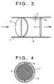
- the first and second embodiments may be further developed in that, a clearance c for permitting a portion of intake air to pass therethrough may be provided between the mesh member 3 and an inside surface of an intake pipe 9 (which is a portion of the intake air passage 7 and in which the mesh member 3 is disposed). More particularly, the mesh member 3 is manufactured so as to have a smaller diameter than the inside surface of the intake pipe 9. Then, the mesh member 3 is disposed within the intake pipe 9 and is supported by support members 8 so that the mesh member 3 is located at a central portion of the intake pipe with the clearance c between the periphery of the mesh member 3 and the inside surface of the intake pipe 9 along an entire circumference of the mesh member 3. The size of the clearance c is selected so as to satisfy both the noise suppressing effect and icing prevention effect.
- the structure of the clearance c may be provided in addition to the structure of any of the first embodiment and the second embodiment.
- the mesh member 3 makes the intake air flow uniform and prevents noise from occurring even when the throttle valve 2 is opened at a high speed.
Landscapes
- Engineering & Computer Science (AREA)
- Chemical & Material Sciences (AREA)
- Combustion & Propulsion (AREA)
- Mechanical Engineering (AREA)
- General Engineering & Computer Science (AREA)
- Control Of Throttle Valves Provided In The Intake System Or In The Exhaust System (AREA)
- Cylinder Crankcases Of Internal Combustion Engines (AREA)
Claims (8)
- Ansaugstruktur für eine Brennkraftmaschine mit:einem Luftansaugkanal (7) einschließlich einem ersten Kanalabschnitt (1) und einem zweiten Kanalabschnitt (6), der sich stromabwärts von dem ersten Kanalabschnitt (1) befindet, wobei der erste Kanalabschnitt (1) eine erste Querschnittsfläche (S1) hat, wobei der zweite Kanalabschnitt (6) eine zweite Querschnittsfläche (S2) hat;einer Drosselklappe (2), die in dem ersten Kanalabschnitt (1) angeordnet ist; undeinem Netzelement (3), das in dem zweiten Kanalabschnitt (6) angeordnet ist, wobei das Netzelement (3) eine Öffnungsflächenrate (α) hat, dadurch gekennzeichnet, dass die erste Querschnittsfläche (S1), die zweite Querschnittsfläche (32) und die Öffnungsflächenrate (α) die folgende Beziehung erfüllen:
- Ansaugstruktur nach Anspruch 1, wobei der erste Kanalabschnitt (1) einen ersten Durchmesser (D1) hat, und wobei der zweite Kanalabschnitt (6) einen zweiten Durchmesser (D2) hat, und wobei der erste Durchmesser (D1), der zweite Durchmesser (D2) und die Öffnungsflächenrate (α) die folgende Beziehung erfüllen:
- Ansaugstruktur nach Anspruch 1, wobei der zweite Kanalabschnitt (6) eine Bodenfläche hat und der erste Kanalabschnitt (1) eine Bodenfläche hat, wobei die Bodenfläche des zweiten Kanalabschnitts (6) bei einer niedrigeren Höhe als die Bodenfläche des ersten Kanalabschnitts angeordnet ist.
- Ansaugstruktur nach Anspruch 3, wobei die Bodenfläche des zweiten Kanalabschnitts (6) mit der Bodenfläche des ersten Kanalabschnitts (1) über eine geneigte Fläche verbunden ist.
- Ansaugstruktur nach Anspruch 3, wobei die Bodenfläche des zweiten Kanalabschnitts (6) mit der Bodenfläche des ersten Kanalabschnitts über eine gestufte Fläche verbunden ist.
- Ansaugstruktur nach Anspruch 1, wobei das Netzelement (3) bei einer von der Drosselklappe (2) beabstandeten Position in einem Abstand (Ln) in dem Bereich von 0,5D1 bis 2D1 angeordnet ist.
- Ansaugstruktur nach einem der Ansprüche 1 bis 6 mit einer Ansaugleitung (9), die den Luftansaugkanal (7) im Inneren definiert, wobei die Ansaugleitung (9) eine Innenfläche hat;wobei die Drosselklappe (2) in der Ansaugleitung (9) angeordnet ist;wobei das Netzelement (3) in der Ansaugleitung (9) so angeordnet ist, dass ein Spalt (c) in der Gestalt eines Rings zum Ermöglichen des Hindurchtretens eines Teil des Ansauggases ausgebildet ist zwischen dem Netzelement (3) und der Innenfläche der Ansaugleitung (9).
- Ansaugkanalstruktur nach Anspruch 7, wobei das Netzelement (3) einen kleineren Durchmesser hat als die Innenfläche der Ansaugleitung (9) und gestützt ist, um bei einem zentralen Abschnitt des Luftansaugkanals (7) so angeordnet zu sein, dass der Spalt (c) zwischen dem Netzelement (3) und der Innenfläche der Ansaugleitung (9) gebildet ist.
Priority Applications (1)
| Application Number | Priority Date | Filing Date | Title |
|---|---|---|---|
| EP00107307A EP1008744B1 (de) | 1996-05-14 | 1997-05-06 | Einlasskanalstruktur für eine Brennkraftmaschine |
Applications Claiming Priority (3)
| Application Number | Priority Date | Filing Date | Title |
|---|---|---|---|
| JP118738/96 | 1996-05-14 | ||
| JP11873896 | 1996-05-14 | ||
| JP11873896A JP3454016B2 (ja) | 1996-05-14 | 1996-05-14 | 内燃機関の吸気通路構造 |
Related Child Applications (1)
| Application Number | Title | Priority Date | Filing Date |
|---|---|---|---|
| EP00107307A Division EP1008744B1 (de) | 1996-05-14 | 1997-05-06 | Einlasskanalstruktur für eine Brennkraftmaschine |
Publications (2)
| Publication Number | Publication Date |
|---|---|
| EP0807755A1 EP0807755A1 (de) | 1997-11-19 |
| EP0807755B1 true EP0807755B1 (de) | 2001-11-14 |
Family
ID=14743854
Family Applications (2)
| Application Number | Title | Priority Date | Filing Date |
|---|---|---|---|
| EP97107445A Expired - Lifetime EP0807755B1 (de) | 1996-05-14 | 1997-05-06 | Einlasskanalstruktur für eine Brennkraftmaschine |
| EP00107307A Expired - Lifetime EP1008744B1 (de) | 1996-05-14 | 1997-05-06 | Einlasskanalstruktur für eine Brennkraftmaschine |
Family Applications After (1)
| Application Number | Title | Priority Date | Filing Date |
|---|---|---|---|
| EP00107307A Expired - Lifetime EP1008744B1 (de) | 1996-05-14 | 1997-05-06 | Einlasskanalstruktur für eine Brennkraftmaschine |
Country Status (5)
| Country | Link |
|---|---|
| US (1) | US5809961A (de) |
| EP (2) | EP0807755B1 (de) |
| JP (1) | JP3454016B2 (de) |
| KR (1) | KR100202794B1 (de) |
| DE (2) | DE69708200T2 (de) |
Families Citing this family (15)
| Publication number | Priority date | Publication date | Assignee | Title |
|---|---|---|---|---|
| US5924398A (en) * | 1997-10-06 | 1999-07-20 | Ford Global Technologies, Inc. | Flow improvement vanes in the intake system of an internal combustion engine |
| JP3726672B2 (ja) * | 2000-11-21 | 2005-12-14 | トヨタ自動車株式会社 | 内燃機関の吸気異音低減部材取付構造 |
| JP2003003920A (ja) * | 2001-06-21 | 2003-01-08 | Denso Corp | 内燃機関の吸気装置 |
| US6994065B2 (en) * | 2003-10-10 | 2006-02-07 | Nissan Motor Co., Ltd. | Intake arrangement for internal combustion engine |
| JP4769651B2 (ja) * | 2005-12-20 | 2011-09-07 | 岩井商事株式会社 | 混合器 |
| JP4928135B2 (ja) * | 2006-02-27 | 2012-05-09 | 株式会社マーレ フィルターシステムズ | 内燃機関の吸気装置および吸気マニホルド |
| JP4615463B2 (ja) * | 2006-03-16 | 2011-01-19 | 興国インテック株式会社 | 吸気異音低減装置及びこれを備えた内燃機関、内燃機関の吸気異音低減装置取付構造 |
| US7255097B1 (en) * | 2006-10-24 | 2007-08-14 | Ching-Tung Huang | Method for increasing performance of automobile and apparatus thereof |
| JP2011127507A (ja) * | 2009-12-17 | 2011-06-30 | Aisan Industry Co Ltd | インテークマニホールド |
| JP5273090B2 (ja) * | 2010-05-12 | 2013-08-28 | 株式会社デンソー | 内燃機関の吸気異音低減装置 |
| US10914229B2 (en) | 2012-09-14 | 2021-02-09 | Ford Global Technologies, Llc | Charge air cooler condensation dispersion element |
| WO2014136666A1 (ja) * | 2013-03-05 | 2014-09-12 | Nok株式会社 | 吸気音低減装置 |
| JP5917588B2 (ja) * | 2014-04-08 | 2016-05-18 | 愛三工業株式会社 | インテークマニホールド |
| CN107076068B (zh) * | 2014-11-14 | 2018-08-14 | Nok株式会社 | 吸气音降低装置 |
| JP6822296B2 (ja) * | 2017-04-20 | 2021-01-27 | トヨタ自動車株式会社 | 燃料電池システム |
Family Cites Families (16)
| Publication number | Priority date | Publication date | Assignee | Title |
|---|---|---|---|---|
| DE466655C (de) * | 1926-06-16 | 1928-10-12 | Abel Defrance | Durchmischvorrichtung fuer Gasgemische |
| FR1008178A (fr) * | 1949-01-11 | 1952-05-14 | Paso Corp Reg Trust | Dispositif applicable aux moteurs à combustion interne |
| CH284184A (de) * | 1950-08-22 | 1952-07-15 | Kuhn Emil | Einrichtung zur Vermischung des Brennstoff-Luft-Gemisches in der Ansaugleitung einer Brennkraftmaschine. |
| US3934569A (en) * | 1973-07-27 | 1976-01-27 | Compression Dynamics, Incorporated | Apparatus and method for atomizing fuel-air mixture in a carburetion system |
| DE2641066A1 (de) * | 1976-09-11 | 1978-03-16 | Bosch Gmbh Robert | Vorrichtung zur aufbereitung des kraftstoff-luft-gemisches |
| FR2370867A1 (fr) * | 1976-11-16 | 1978-06-09 | Pellerin Albert | Dispositif rendant plus homogene le melange air-essence dans les moteurs a explosion |
| JPS57107838U (de) | 1980-12-19 | 1982-07-03 | ||
| JPS57107838A (en) * | 1980-12-26 | 1982-07-05 | Toshin Kogyo Kk | Continuous cloth supplying apparatus of automatic screen printing machine |
| JPS59213922A (ja) * | 1983-05-19 | 1984-12-03 | Nissan Motor Co Ltd | 内燃機関の吸気装置 |
| US4667648A (en) * | 1986-03-04 | 1987-05-26 | Beldin Leroy E | Vaporizing assembly |
| GB2202276B (en) * | 1987-03-09 | 1991-09-18 | Honda Motor Co Ltd | Intake device for internal combustion engine |
| JPH0252489A (ja) * | 1988-08-16 | 1990-02-22 | Toshiba Corp | プリント配線板 |
| US4986225A (en) * | 1990-06-08 | 1991-01-22 | General Motors Corporation | Intake reservoir system for an engine having a check valve |
| WO1994004816A1 (de) * | 1992-08-22 | 1994-03-03 | Dr.Ing. H.C.F. Porsche Aktiengesellschaft | Brennkraftmaschine mit einer ansauganlage |
| GB2270952A (en) * | 1992-09-24 | 1994-03-30 | Keefe Michael O | I.c.engine carburetted mixture atomiser. |
| US5323753A (en) * | 1992-10-19 | 1994-06-28 | Ford Motor Company | Induction system for an internal combustion engine |
-
1996
- 1996-05-14 JP JP11873896A patent/JP3454016B2/ja not_active Expired - Fee Related
-
1997
- 1997-01-31 KR KR1019970002908A patent/KR100202794B1/ko not_active Expired - Fee Related
- 1997-05-06 DE DE69708200T patent/DE69708200T2/de not_active Expired - Fee Related
- 1997-05-06 EP EP97107445A patent/EP0807755B1/de not_active Expired - Lifetime
- 1997-05-06 DE DE69717164T patent/DE69717164T2/de not_active Expired - Fee Related
- 1997-05-06 EP EP00107307A patent/EP1008744B1/de not_active Expired - Lifetime
- 1997-05-09 US US08/853,671 patent/US5809961A/en not_active Expired - Fee Related
Also Published As
| Publication number | Publication date |
|---|---|
| DE69708200D1 (de) | 2001-12-20 |
| DE69708200T2 (de) | 2002-06-06 |
| JP3454016B2 (ja) | 2003-10-06 |
| DE69717164D1 (de) | 2002-12-19 |
| KR970075315A (ko) | 1997-12-10 |
| EP1008744A3 (de) | 2000-08-30 |
| US5809961A (en) | 1998-09-22 |
| JPH09303223A (ja) | 1997-11-25 |
| KR100202794B1 (ko) | 1999-06-15 |
| EP1008744A2 (de) | 2000-06-14 |
| DE69717164T2 (de) | 2003-05-08 |
| EP1008744B1 (de) | 2002-11-13 |
| EP0807755A1 (de) | 1997-11-19 |
Similar Documents
| Publication | Publication Date | Title |
|---|---|---|
| EP0807755B1 (de) | Einlasskanalstruktur für eine Brennkraftmaschine | |
| US7980357B2 (en) | Exhaust silencer for microturbines | |
| US4903484A (en) | Exhaust dissipator and deflector | |
| US5504280A (en) | Muffler for marine engines | |
| US5934959A (en) | Marine muffler | |
| JPH11141416A (ja) | 吸気異音低減構造 | |
| US20020125068A1 (en) | Weatherproof sound attenuating device | |
| GB2146070A (en) | I C engine air intake silencing | |
| US2630748A (en) | Exhaust rain protector | |
| CA2265421A1 (en) | Furnace vent and intake terminal and blockage safety shut down system | |
| WO2000040463A1 (en) | Anti ingestion device | |
| US5161371A (en) | Exhaust outlet with cleaner | |
| JP4301074B2 (ja) | 多気筒エンジンの吸気装置 | |
| US4548167A (en) | Suction air passage of internal combustion engine | |
| JPH10184471A (ja) | ドレーントラップ | |
| JP3188066B2 (ja) | フューエルカットオフバルブ装置 | |
| JP3430840B2 (ja) | スロットル弁の気流騒音防止装置 | |
| JP2540860Y2 (ja) | ブローバイガス還流装置 | |
| JP3131763B2 (ja) | 止め弁の構造 | |
| US3156225A (en) | Internal combustion engine and auxiliary manifold air intake therefor | |
| JP3448124B2 (ja) | ターボチャージ付内燃機関 | |
| JPS618431A (ja) | 絞弁組立体 | |
| JP3189658B2 (ja) | 内燃機関の吸気装置 | |
| JPH05321677A (ja) | エンジンの吸気制御装置 | |
| JP3540693B2 (ja) | 火花点火式エンジンの気体燃料ミキサのミキシングボディを転用する方法 |
Legal Events
| Date | Code | Title | Description |
|---|---|---|---|
| PUAI | Public reference made under article 153(3) epc to a published international application that has entered the european phase |
Free format text: ORIGINAL CODE: 0009012 |
|
| 17P | Request for examination filed |
Effective date: 19970506 |
|
| AK | Designated contracting states |
Kind code of ref document: A1 Designated state(s): DE FR GB |
|
| 17Q | First examination report despatched |
Effective date: 19991014 |
|
| GRAG | Despatch of communication of intention to grant |
Free format text: ORIGINAL CODE: EPIDOS AGRA |
|
| GRAG | Despatch of communication of intention to grant |
Free format text: ORIGINAL CODE: EPIDOS AGRA |
|
| GRAH | Despatch of communication of intention to grant a patent |
Free format text: ORIGINAL CODE: EPIDOS IGRA |
|
| GRAH | Despatch of communication of intention to grant a patent |
Free format text: ORIGINAL CODE: EPIDOS IGRA |
|
| GRAA | (expected) grant |
Free format text: ORIGINAL CODE: 0009210 |
|
| AK | Designated contracting states |
Kind code of ref document: B1 Designated state(s): DE FR GB |
|
| REF | Corresponds to: |
Ref document number: 69708200 Country of ref document: DE Date of ref document: 20011220 |
|
| ET | Fr: translation filed | ||
| REG | Reference to a national code |
Ref country code: GB Ref legal event code: IF02 |
|
| PLBE | No opposition filed within time limit |
Free format text: ORIGINAL CODE: 0009261 |
|
| STAA | Information on the status of an ep patent application or granted ep patent |
Free format text: STATUS: NO OPPOSITION FILED WITHIN TIME LIMIT |
|
| 26N | No opposition filed | ||
| PGFP | Annual fee paid to national office [announced via postgrant information from national office to epo] |
Ref country code: GB Payment date: 20060503 Year of fee payment: 10 |
|
| PGFP | Annual fee paid to national office [announced via postgrant information from national office to epo] |
Ref country code: DE Payment date: 20060508 Year of fee payment: 10 |
|
| PGFP | Annual fee paid to national office [announced via postgrant information from national office to epo] |
Ref country code: FR Payment date: 20060515 Year of fee payment: 10 |
|
| GBPC | Gb: european patent ceased through non-payment of renewal fee |
Effective date: 20070506 |
|
| REG | Reference to a national code |
Ref country code: FR Ref legal event code: ST Effective date: 20080131 |
|
| PG25 | Lapsed in a contracting state [announced via postgrant information from national office to epo] |
Ref country code: DE Free format text: LAPSE BECAUSE OF NON-PAYMENT OF DUE FEES Effective date: 20071201 |
|
| PG25 | Lapsed in a contracting state [announced via postgrant information from national office to epo] |
Ref country code: GB Free format text: LAPSE BECAUSE OF NON-PAYMENT OF DUE FEES Effective date: 20070506 |
|
| PG25 | Lapsed in a contracting state [announced via postgrant information from national office to epo] |
Ref country code: FR Free format text: LAPSE BECAUSE OF NON-PAYMENT OF DUE FEES Effective date: 20070531 |