EP0807428A2 - Générateur de vapeur pour sauna - Google Patents
Générateur de vapeur pour sauna Download PDFInfo
- Publication number
- EP0807428A2 EP0807428A2 EP97102482A EP97102482A EP0807428A2 EP 0807428 A2 EP0807428 A2 EP 0807428A2 EP 97102482 A EP97102482 A EP 97102482A EP 97102482 A EP97102482 A EP 97102482A EP 0807428 A2 EP0807428 A2 EP 0807428A2
- Authority
- EP
- European Patent Office
- Prior art keywords
- condensate
- steam
- container
- evaporator
- evaporator system
- Prior art date
- Legal status (The legal status is an assumption and is not a legal conclusion. Google has not performed a legal analysis and makes no representation as to the accuracy of the status listed.)
- Granted
Links
Images


Classifications
-
- A—HUMAN NECESSITIES
- A61—MEDICAL OR VETERINARY SCIENCE; HYGIENE
- A61H—PHYSICAL THERAPY APPARATUS, e.g. DEVICES FOR LOCATING OR STIMULATING REFLEX POINTS IN THE BODY; ARTIFICIAL RESPIRATION; MASSAGE; BATHING DEVICES FOR SPECIAL THERAPEUTIC OR HYGIENIC PURPOSES OR SPECIFIC PARTS OF THE BODY
- A61H33/00—Bathing devices for special therapeutic or hygienic purposes
- A61H33/06—Artificial hot-air or cold-air baths; Steam or gas baths or douches, e.g. sauna or Finnish baths
- A61H33/063—Heaters specifically designed therefor
Definitions
- the invention relates to an evaporator system for sauna systems.
- evaporator systems for sauna systems.
- evaporator systems are on the market, which are either combined with the usual sauna heater or can also be retrofitted in existing systems.
- the additional device is designed in such a way that it uses the available space without, however, reducing the bathing area.
- the additional device should still be easy to use, of course, with minimal maintenance.
- Another requirement is that the evaporator system should save energy.
- the water for steam generation is either heated according to the immersion heater principle, i.e. a heating element is arranged in the water container that is in direct contact with the water, or a pipe is provided, similarly to coffee machines, as a feed line to the herb container, in which rises to produce steam and is heated by a heating jacket surrounding the pipe.
- a heating element is arranged in the water container that is in direct contact with the water, or a pipe is provided, similarly to coffee machines, as a feed line to the herb container, in which rises to produce steam and is heated by a heating jacket surrounding the pipe.
- trays for receiving herbs are arranged, which are heated by the steam, so that vapors rise from the herbs or essential oils, which then pass over the steam from the steam generator mix and be led into the bathroom.
- the object of the present invention is to provide an evaporator system which avoids the disadvantages of the prior art shown above.
- the object is achieved by the features of claim 1. These features ensure that when the herbal vapors are used and mixed well with the steam, no condensate gets into the steam generating container, contaminates it and encrypts the heating. The evaporation system is therefore almost maintenance-free.
- the collecting device preferably consists of two shields which are offset from one another and arranged one above the other, which collect the condensate and discharge it into a collecting channel, where it is collected.
- a condensate tank can also be connected to the collecting trough.
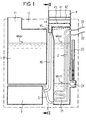
- the evaporator system 10 consists of the storage container 1, the evaporator 2, and the condensate container 3, which is arranged under the storage container 1.
- the water storage container 1 is connected by a line 5 to the evaporator 2, so that both containers communicate with one another and the water level in both containers also remains at the same level.
- a filler neck 11 is provided for filling the water into the reservoir.
- the evaporator 2 takes up a substantially smaller amount of water than that contained in the storage container 1.
- a heating element 21, which is fed through the power lines 22, is immersed in this amount of water.
- a water level sensor 24 regulates the water level W so that it does not drop below Wmin. Should the water level drop below Wmin due to the emptying of the storage container, the water level sensor 24 automatically switches off the heating element 21. According to the water level in the reservoir 1, the water level fluctuates between Wmax and Wmin and is indicated by the water level indicator 23.
- the heating element 21 can always heat only the amount of water in the evaporator 2. In this way, steam D is generated after a short switch-on time.
- an attachment 4 is placed, in which herbs K or other ethereal substances are introduced.
- the herbs K are placed on a shelf 41 designed as a sieve.
- condensate forms, which prevents the herbs K from overheating and the ethereal substances being destroyed. So that the condensate that forms does not get into the evaporator 2 and is deposited there, a collecting device for the condensate is provided.
- two inclined shields 42, 43 are arranged under the screen 41 of the attachment 4 at a distance from one another and offset.
- the shield 42 connects to the front attachment wall 47, but leaves a passage between the rear attachment wall 48 free.
- the passage is located on the side of the front attachment wall 47.
- the steam D rising from the evaporator 2 first strokes the shield 43 and passes through the passage formed to the front wall 47 between the two shields 42, 43 and finally flows between the shield 42 and the rear attachment wall 48 against the sieve 41, on which the herbs K are introduced.
- the sieve 41 and thus also the herbs K are flowed through by the steam D, which takes the etheric substances with them and conveys them to the bathroom.
- connection piece 45 and the condensate line 46 which connect the collecting channel 44 to the condensate container 3, are used.
- the evaporator system 10 is assembled into a compact apparatus and therefore requires very little space.
- the evaporator system 10 can expediently be arranged in the space between the protective grille 6 and the sauna heater 7 itself, which according to the regulations should have a width of at least 7 cm. This arrangement makes it easy and safe to operate the evaporator system 10. It is avoided to long over the hot oven 7 and yet no additional space in the bathroom is required.
- the storage container 1 and the evaporator 2 communicate.
- the water levels in the storage container 1 and in the evaporator 2 are always at the same level. This means that the water level in the evaporator 2 can fluctuate between Wmax and Wmin, depending on how strongly the reservoir 1 is filled. As a result, more and more water would have to be heated up, depending on the fill level, especially when the evaporation system was operating.
- the regulation by the water level sensor 24 can also take place in such a way that a valve is provided in the inlet line 5, which is opened depending on the desired water level, so that only a very specific amount of water is to be heated at all times.
- the line 5 can be connected directly to the tap water network, so that the water level sensor 24 regulates the water level directly from the water line with a control valve.
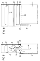
- FIGS. 5 and 6 show another embodiment of the attachment 8, the front wall being omitted in the view for a better understanding of the arrangement inside the attachment 8.
- the attachment 8 is placed on the evaporator 2, which comprises the attachment 8 in its fork-like length.
- the cover 83 forms the bottom of the attachment 8 and is pulled upwards in the middle, so that two bevels are formed which open into a passage 84.
- Above passage 84 is the upper one Cover 82 is arranged, which prevents the condensate from dripping into the passage and thus into the evaporator 2.
- the shield 83 forms a collecting channel 85 with the side walls.
- the two collecting channels 85 are brought together by a connection 87, the connection 87 being connected to the condensate container 3 by a connecting line 86.
- an evaporation system in which the steam generating container 2 and the storage container 1 are separated in order to bring only a small amount of water to the evaporation in each case.
- This evaporation system 10 can also be used advantageously without the attachment 4 with a collecting device for the condensate, just as the attachment 4 can advantageously be used without the separation of the steam generation container 2 and the water storage container 1.
- both devices combined result in the sum of the advantages and thus a particularly advantageous evaporator system.
Landscapes
- Health & Medical Sciences (AREA)
- Public Health (AREA)
- Epidemiology (AREA)
- Pain & Pain Management (AREA)
- Physical Education & Sports Medicine (AREA)
- Rehabilitation Therapy (AREA)
- Life Sciences & Earth Sciences (AREA)
- Animal Behavior & Ethology (AREA)
- General Health & Medical Sciences (AREA)
- Veterinary Medicine (AREA)
- Devices For Medical Bathing And Washing (AREA)
- Vaporization, Distillation, Condensation, Sublimation, And Cold Traps (AREA)
Applications Claiming Priority (2)
| Application Number | Priority Date | Filing Date | Title |
|---|---|---|---|
| DE19606346A DE19606346C2 (de) | 1996-02-21 | 1996-02-21 | Verdampfersystem für Sauna-Anlagen |
| DE19606346 | 1996-02-21 |
Publications (3)
| Publication Number | Publication Date |
|---|---|
| EP0807428A2 true EP0807428A2 (fr) | 1997-11-19 |
| EP0807428A3 EP0807428A3 (fr) | 1998-03-25 |
| EP0807428B1 EP0807428B1 (fr) | 2001-11-28 |
Family
ID=7785945
Family Applications (1)
| Application Number | Title | Priority Date | Filing Date |
|---|---|---|---|
| EP97102482A Expired - Lifetime EP0807428B1 (fr) | 1996-02-21 | 1997-02-15 | Générateur de vapeur pour sauna |
Country Status (4)
| Country | Link |
|---|---|
| EP (1) | EP0807428B1 (fr) |
| AT (1) | ATE209476T1 (fr) |
| DE (2) | DE19606346C2 (fr) |
| ES (1) | ES2169283T3 (fr) |
Cited By (1)
| Publication number | Priority date | Publication date | Assignee | Title |
|---|---|---|---|---|
| WO2008129119A1 (fr) | 2007-04-19 | 2008-10-30 | Pertti Harvia | Générateur de vapeur, procédé de fonctionnement d'un générateur de vapeur et réservoir d'un générateur de vapeur |
Families Citing this family (8)
| Publication number | Priority date | Publication date | Assignee | Title |
|---|---|---|---|---|
| DE29716620U1 (de) * | 1997-09-16 | 1997-11-13 | Meier, Hansjürgen, 32339 Espelkamp | Installierbare Vorrichtung zur Dampferzeugung für eine Duschkabine |
| DE20103108U1 (de) * | 2001-02-21 | 2002-07-04 | Klafs Saunabau GmbH & Co Medizinische Technik, 74523 Schwäbisch Hall | Saunaofen mit Verdampfereinrichtung |
| DE20103253U1 (de) * | 2001-02-23 | 2002-07-04 | Klafs Saunabau GmbH & Co Medizinische Technik, 74523 Schwäbisch Hall | Verdampfereinheit für eine Sauna- oder Dampfbadkabine und Befüllgefäß |
| DE10259260A1 (de) * | 2002-12-12 | 2004-06-24 | Hansgrohe Ag | Vorrichtung zur Dufterzeugung mit einer Dampferzeugung |
| DE202005019488U1 (de) * | 2005-12-13 | 2007-04-19 | Hans Einhell Ag | Saunaheizgerät |
| DE102008026473A1 (de) | 2008-06-03 | 2009-12-10 | Dannenmann, Gudrun | Saunaofen mit Konvektionsheizung, kombiniert mit Infrarotheizung, in besonders hygienischer und gesundheitsbewußter und energiesparender Ausführung, wahlweise regelbar |
| DE102012019875A1 (de) | 2012-10-10 | 2014-04-10 | Johanna Bozena Dannenmann | Saunaofen oder Saunaofen mit Dampfeinrichtung, kombiniert mit Licht-Farblicht auch für Farb-Chromotherapie, HF-Abschirmungseinrichtung |
| EP3569215B1 (fr) | 2018-05-17 | 2020-09-09 | Klafs GmbH & Co. KG | Cabine de bains de vapeur pour personnes |
Family Cites Families (8)
| Publication number | Priority date | Publication date | Assignee | Title |
|---|---|---|---|---|
| US2332402A (en) * | 1941-07-25 | 1943-10-19 | Seikowitz Jack | Therapeutic device |
| DE3109540A1 (de) * | 1981-03-13 | 1982-09-23 | Eberhard Hoesch & Söhne Kunststoffwerk KG, 5160 Düren | Dampfaustritt fuer ein dampfbad |
| DE3404892A1 (de) * | 1984-02-11 | 1985-08-14 | Dannenmann, Gudrun, 7060 Schorndorf | Saunaofen |
| CH674144A5 (fr) * | 1987-10-01 | 1990-05-15 | Josef Balthasar Arnold | |
| DE3913280C2 (de) * | 1989-04-22 | 1995-02-16 | Paul Haslauer | Bedampfungsgerät |
| GB2241051B (en) * | 1990-02-19 | 1994-05-18 | Helo Tehtaat Oy | An electric sauna heater |
| DE4132042A1 (de) * | 1991-09-26 | 1993-04-01 | Dannenmann Gudrun | Selbsttaetigende niveauregelung fuer fluessigkeiten |
| DE4328376A1 (de) * | 1993-08-24 | 1995-03-16 | Dannenmann Gudrun | Vorrichtung zum Verdampfen von Flüssigkeit |
-
1996
- 1996-02-21 DE DE19606346A patent/DE19606346C2/de not_active Expired - Fee Related
-
1997
- 1997-02-15 ES ES97102482T patent/ES2169283T3/es not_active Expired - Lifetime
- 1997-02-15 DE DE59705494T patent/DE59705494D1/de not_active Expired - Fee Related
- 1997-02-15 AT AT97102482T patent/ATE209476T1/de not_active IP Right Cessation
- 1997-02-15 EP EP97102482A patent/EP0807428B1/fr not_active Expired - Lifetime
Cited By (1)
| Publication number | Priority date | Publication date | Assignee | Title |
|---|---|---|---|---|
| WO2008129119A1 (fr) | 2007-04-19 | 2008-10-30 | Pertti Harvia | Générateur de vapeur, procédé de fonctionnement d'un générateur de vapeur et réservoir d'un générateur de vapeur |
Also Published As
| Publication number | Publication date |
|---|---|
| DE19606346C2 (de) | 1998-07-16 |
| DE19606346A1 (de) | 1997-08-28 |
| ES2169283T3 (es) | 2002-07-01 |
| EP0807428A3 (fr) | 1998-03-25 |
| DE59705494D1 (de) | 2002-01-10 |
| ATE209476T1 (de) | 2001-12-15 |
| EP0807428B1 (fr) | 2001-11-28 |
Similar Documents
| Publication | Publication Date | Title |
|---|---|---|
| EP0383327B1 (fr) | Chaudière à vapeur avec détartrage pour appareil de cuisson | |
| DE2419734B2 (de) | Selbstreinigendes dampfbuegeleisen | |
| DE69118036T2 (de) | Vorrichtung zur Lieferung von kochendem Wasser | |
| EP3225139A1 (fr) | Dispositif d'evaporation pour l'eau | |
| EP0807428B1 (fr) | Générateur de vapeur pour sauna | |
| DE3526186A1 (de) | Elektrische beheizung fuer fluessigkeits-behaelter | |
| DE3015677C2 (de) | Vorrichtung zum Auffangen von zum Reinigen eines Röhrenwärmetauschers verwendeten Reinigungskörpern | |
| DE3121220C2 (de) | Wassererhitzer | |
| DE1794237A1 (de) | Fallstromverdampfer | |
| DE3109540A1 (de) | Dampfaustritt fuer ein dampfbad | |
| EP0363708A2 (fr) | Appareil calorifique pour des fluides | |
| DE69403127T2 (de) | Kaffeemaschine mit Wasserrückführungsschacht | |
| DE19642106C1 (de) | Vorrichtung zur diskontinuierlichen Zubereitung von Teigwaren | |
| DE1817352A1 (de) | Vorrichtung zur Dampferzeugung fuer Luftbefeuchtung | |
| DE2741719C3 (de) | Elektrische Kaffee- oder Teemaschine | |
| EP0011290A1 (fr) | Machine à café express | |
| DE3214064A1 (de) | Vorrichtung zum schwadenabzug an einer maische- und/oder wuerzepfanne | |
| EP3805648A1 (fr) | Système d'évaporateur pour un appareil électroménager ainsi qu'appareil électroménager | |
| EP0751835A1 (fr) | Systeme de conservation d'espaces creux | |
| DE1926814A1 (de) | Wasserreinigungsvorrichtung | |
| EP0454744B1 (fr) | Dispositif pour la preparation d'eau chaude | |
| AT411142B (de) | Getränkeerhitzer | |
| EP1916928B1 (fr) | Dispositif de cuisson à la vapeur | |
| DE1579355C (de) | Heißwasserbereiter fur Kaffee maschinen | |
| EP3218299B2 (fr) | Appareil de préparation de boissons |
Legal Events
| Date | Code | Title | Description |
|---|---|---|---|
| PUAI | Public reference made under article 153(3) epc to a published international application that has entered the european phase |
Free format text: ORIGINAL CODE: 0009012 |
|
| AK | Designated contracting states |
Kind code of ref document: A2 Designated state(s): AT CH DE ES FI FR IT LI NL |
|
| PUAL | Search report despatched |
Free format text: ORIGINAL CODE: 0009013 |
|
| AK | Designated contracting states |
Kind code of ref document: A3 Designated state(s): AT CH DE ES FI FR IT LI NL |
|
| 17P | Request for examination filed |
Effective date: 19980923 |
|
| GRAG | Despatch of communication of intention to grant |
Free format text: ORIGINAL CODE: EPIDOS AGRA |
|
| 17Q | First examination report despatched |
Effective date: 20010222 |
|
| GRAG | Despatch of communication of intention to grant |
Free format text: ORIGINAL CODE: EPIDOS AGRA |
|
| GRAH | Despatch of communication of intention to grant a patent |
Free format text: ORIGINAL CODE: EPIDOS IGRA |
|
| GRAH | Despatch of communication of intention to grant a patent |
Free format text: ORIGINAL CODE: EPIDOS IGRA |
|
| GRAA | (expected) grant |
Free format text: ORIGINAL CODE: 0009210 |
|
| AK | Designated contracting states |
Kind code of ref document: B1 Designated state(s): AT CH DE ES FI FR IT LI NL |
|
| PG25 | Lapsed in a contracting state [announced via postgrant information from national office to epo] |
Ref country code: NL Free format text: LAPSE BECAUSE OF FAILURE TO SUBMIT A TRANSLATION OF THE DESCRIPTION OR TO PAY THE FEE WITHIN THE PRESCRIBED TIME-LIMIT Effective date: 20011128 |
|
| REF | Corresponds to: |
Ref document number: 209476 Country of ref document: AT Date of ref document: 20011215 Kind code of ref document: T |
|
| REG | Reference to a national code |
Ref country code: CH Ref legal event code: EP |
|
| REF | Corresponds to: |
Ref document number: 59705494 Country of ref document: DE Date of ref document: 20020110 |
|
| REG | Reference to a national code |
Ref country code: CH Ref legal event code: NV Representative=s name: SPIERENBURG HELMLE-KOLB & PARTNER AG PATENT- UND M |
|
| PGFP | Annual fee paid to national office [announced via postgrant information from national office to epo] |
Ref country code: DE Payment date: 20020312 Year of fee payment: 6 |
|
| PGFP | Annual fee paid to national office [announced via postgrant information from national office to epo] |
Ref country code: FR Payment date: 20020322 Year of fee payment: 6 |
|
| PGFP | Annual fee paid to national office [announced via postgrant information from national office to epo] |
Ref country code: ES Payment date: 20020325 Year of fee payment: 6 Ref country code: CH Payment date: 20020325 Year of fee payment: 6 Ref country code: AT Payment date: 20020325 Year of fee payment: 6 |
|
| PGFP | Annual fee paid to national office [announced via postgrant information from national office to epo] |
Ref country code: FI Payment date: 20020328 Year of fee payment: 6 |
|
| NLV1 | Nl: lapsed or annulled due to failure to fulfill the requirements of art. 29p and 29m of the patents act | ||
| ET | Fr: translation filed | ||
| REG | Reference to a national code |
Ref country code: ES Ref legal event code: FG2A Ref document number: 2169283 Country of ref document: ES Kind code of ref document: T3 |
|
| PLBE | No opposition filed within time limit |
Free format text: ORIGINAL CODE: 0009261 |
|
| STAA | Information on the status of an ep patent application or granted ep patent |
Free format text: STATUS: NO OPPOSITION FILED WITHIN TIME LIMIT |
|
| 26N | No opposition filed | ||
| PG25 | Lapsed in a contracting state [announced via postgrant information from national office to epo] |
Ref country code: FI Free format text: LAPSE BECAUSE OF NON-PAYMENT OF DUE FEES Effective date: 20030215 Ref country code: AT Free format text: LAPSE BECAUSE OF NON-PAYMENT OF DUE FEES Effective date: 20030215 |
|
| PG25 | Lapsed in a contracting state [announced via postgrant information from national office to epo] |
Ref country code: ES Free format text: LAPSE BECAUSE OF NON-PAYMENT OF DUE FEES Effective date: 20030217 |
|
| PG25 | Lapsed in a contracting state [announced via postgrant information from national office to epo] |
Ref country code: LI Free format text: LAPSE BECAUSE OF NON-PAYMENT OF DUE FEES Effective date: 20030228 Ref country code: CH Free format text: LAPSE BECAUSE OF NON-PAYMENT OF DUE FEES Effective date: 20030228 |
|
| PG25 | Lapsed in a contracting state [announced via postgrant information from national office to epo] |
Ref country code: DE Free format text: LAPSE BECAUSE OF NON-PAYMENT OF DUE FEES Effective date: 20030902 |
|
| REG | Reference to a national code |
Ref country code: CH Ref legal event code: PL |
|
| PG25 | Lapsed in a contracting state [announced via postgrant information from national office to epo] |
Ref country code: FR Free format text: LAPSE BECAUSE OF NON-PAYMENT OF DUE FEES Effective date: 20031031 |
|
| REG | Reference to a national code |
Ref country code: FR Ref legal event code: ST |
|
| REG | Reference to a national code |
Ref country code: ES Ref legal event code: FD2A Effective date: 20030217 |
|
| PG25 | Lapsed in a contracting state [announced via postgrant information from national office to epo] |
Ref country code: IT Free format text: LAPSE BECAUSE OF NON-PAYMENT OF DUE FEES Effective date: 20050215 |